Review

Recent Advances in Preparation, Mechanisms, and Applications of Thermally Conductive Polymer Composites: A Review

1
College of Mechanical and Electrical Engineering, Beijing University of Chemical Technology, Beijing 100029, China
2
State Key Laboratory of Organic-Inorganic Composites, Beijing University of Chemical Technology, Beijing 100029, China
*
Authors to whom correspondence should be addressed.
These authors contribute equally.
J. Compos. Sci. 2020, 4(4), 180; https://doi.org/10.3390/jcs4040180
Submission received: 24 October 2020 / Revised: 23 November 2020 / Accepted: 24 November 2020 / Published: 29 November 2020
(This article belongs to the Special Issue Polymer Composites: Fabrication and Applications)

Abstract

:
At present, the rapid accumulation of heat and the heat dissipation of electronic equipment and related components are important reasons that restrict the miniaturization, high integration, and high power of electronic equipment. It seriously affects the performance and life of electronic devices. Hence, improving the thermal conductivity of polymer composites (TCPCs) is the key to solving this problem. Compared with manufacturing intrinsic thermally conductive polymer composites, the method of filling the polymer matrix with thermally conductive fillers can better-enhance the thermal conductivity (λ) of the composites. This review starts from the thermal conduction mechanism and describes the factors affecting the λ of polymer composites, including filler type, filler morphology and distribution, and the functional surface treatment of fillers. Next, we introduce the preparation methods of filled thermally conductive polymer composites with different filler types. In addition, some commonly used thermal-conductivity theoretical models have been introduced to better-analyze the thermophysical properties of polymer composites. We discuss the simulation of λ and the thermal conduction process of polymer composites based on molecular dynamics and finite element analysis methods. Meanwhile, we briefly introduce the application of polymer composites in thermal management. Finally, we outline the challenges and prospects of TCPCs.

1. Introduction

At present, the rapid development of highly integrated and high-power microelectronic devices, 5G semiconductor chips, and integrated circuits has led to the continuous reduction in product size and increment in product power [1,2]. The electronic equipment and its associated components produce a large amount of heat during operation, so the heat generated will be in certain locations, resulting in the problem of local overheating [3,4]. Therefore, the problem of rapid heat accumulation and heat dissipation becomes increasingly more prominent, seriously affecting the stability and service life of electronic products, and is also one of the most important difficulties at present [5,6,7]. There is evidence that the performance of electronic products decreases by 10% when the temperature increases to 2 °C [8]. Hence, it is extremely urgent to prepare thermal management materials (TMMs) with excellent comprehensive properties [9]. Thermal interface materials (TIMs) for the thermal management system of key components, which is usually made of polymer composites, can fill the space between the two surfaces, thus increasing the effective contact area. TIMs have a significant improvement in interface heat transfer, because the λ of air between two surfaces is particularly low (0.026 W/m·K). Consequently, TIMs play an important role in the heat dissipation of electronic devices.
Polymer composites are widely used in various fields due to their excellent comprehensive properties such as light weight, corrosion resistance, excellent flexibility, convenient processing, and low cost. However, the inherent λ of most polymer substrates is very low (0.1–0.5 W/m·K) [3,4,10,11,12], which severely limits their wide application in the above applications [13,14]. In the past few decades, due to the excessive interfacial thermal resistance in the contact between the filler–filler and filler–matrix interface of polymer composites, and the uneven distribution of fillers in the matrices, the λ of polymer composites has not improved significantly even if the filler load is very large. The greater the load, the worse the mechanical properties of composites. The research on thermal composites will encounter great challenges. Although the λ of composites has been greatly improved in theory, its effect in practical applications is not satisfactory. At present, there are many commonly used methods to prepare thermally conductive composites, including chemical vapor deposition (CVD) [15], plasma treatment [16,17], freeze casting [18], solid-phase extrusion (SPE) [19], the sol–gel method [20], blending method [21], hot-pressed forming method [22,23], forced network assembly [24,25,26], salt template [27], vacuum-assisted filtration [28], and ultrasonic forced infiltration [29,30,31], etc. Many researchers have paid more attention to the study of thermally conductive polymer composites (TCPCs) with outstanding comprehensive properties. They use different materials and various proportions or introduce other new ways to improve λ, in order to reduce the contact thermal resistance of polymer composites, further improve fillers in the polymer matrices distribution, and build a more perfect thermal conduction network [10].
This work reviews three forms of heat transfer (thermal conduction, thermal radiation, and thermal convection) and three accepted theories of heat conduction mechanisms (heat conduction path theory, percolation theory, and thermoelastic coefficient theory). Next, the influencing factors of the λ of TCPCs are expounded, including filler type, filler morphology and distribution, and the functional surface treatment of fillers, and the preparation methods of TCPCs that possess superior comprehensive properties are introduced in detail. Moreover, this review also introduces several common theoretical models of λ and the characteristics of each model in detail. By using these models, the thermal and physical properties of composites can be better-understood, and reasonable prediction results are given. Various methods can be used to simulate the thermal properties of composites, and the model and simulation can be used to verify and predict the best λ of the composites. The application of TIMs in electronic equipment is also introduced. Finally, the challenges and prospects of TCPCs are discussed.

2. Thermal Conduction Mechanisms

In general, heat transfer can be conducted in three basic ways: Thermal conduction, thermal convection, thermal radiation [32,33]. Thermal conduction refers to the process of heat energy transfer caused by the existence of temperature differences in objects. Thermal convection is a process in which heat flows through a fluid medium to stabilize the temperature uniformly. Thermal radiation refers to the phenomenon that the object holds temperature and emits energy in the form of electromagnetic waves. The heat transfer mechanisms of gases, liquids, and solids are different. Thermal conduction is the main method of heat transfer in solids. In liquids and gases, the process of thermal conduction often occurs at the same time as thermal convection, but thermal convection is a unique method of heat transfer in liquids and gases. Thermal radiation is also a way of heat transfer, but it is distinguishable from thermal conduction and thermal convection; it does not rely on the medium to transfer heat, yet emits energy in the form of electromagnetic radiation.
The essence of heat conduction refers to the process that the thermal motions of molecules in a substance collide with each other to transfer energy. In solid materials, due to the difference in temperature, the kinetic energy of the particles at the nodes in the crystal is different. The heat energy inside the crystal is transferred from the part with high kinetic energy to the part with low kinetic energy. In conductive material, there are a large number of free electrons that are constantly making irregular thermal motions, and the general lattice vibration energy is low, so free electrons play a major role in heat conduction. In insulated conductors, the main form of thermal conduction is the lattice vibration of atoms and molecules near their equilibrium positions. The normal-mode energy quantum of lattice vibration is called the phonon [32,34,35,36]. The phonon has no mass and obeys Bose–Einstein theory [33].
Polymers usually have no free electrons, and their thermal conduction mainly relies on phonon transport. However, the polymer has characteristics of the random entanglement of molecular chains and high relative molecular mass, so it is difficult to crystallize completely. These factors can lead to phonon scattering and hinder phonon transfer. Therefore, the λ of most polymer composites were relatively poor (0.1–0.5 W/m·K) [4,11,37,38,39,40]. At present, the synthesis of intrinsic thermally conductive polymers and the preparation of filled thermally conductive polymers are the two main methods for obtaining high TCPCs. Intrinsic thermally conductive polymers mainly change the molecular chain structure of the polymer to obtain an ordered structure, thereby enhancing the λ of composites. The filled thermally conductive polymer is stuffed with high-thermal-conductivity inorganic fillers or metal fillers in the polymer matrices to obtain high TCPCs. Compared with the low fabrication efficiency, cumbersome synthesis process, and high cost for the synthesis of intrinsic thermally conductive polymer composites, the fabrication of the filled thermally conductive polymers shows the advantages of easy operation, low cost, and suitability for industrial production. It has already become the mainstream development direction of TCPCs [32,41,42,43,44].
The addition of high-thermal-conductivity fillers to polymer matrices can effectively improve the λ of composites. However, the thermal conductivity mechanism of TCPCs will become very complicated because it is related to the filler type, filler structure, filler distribution, filler content, interface thermal resistance, and intrinsic thermal conductivity of the fillers. Currently, thermal conduction path theory, percolation theory, and thermoelastic coefficient theories are the accepted explanation of the thermal conductivity mechanism of TCPCs [33,36,45,46,47].
The thermal conduction path theory is, when the thermally conductive fillers are added to the polymer matrices, the thermally conductive fillers form continuous networks inside the polymer matrices, and heat is conducted along the filler network [9,48,49]. This theory feels easy to accept.
Percolation theory is similar to thermal conduction path theory. Percolation theory refers to, when the filler load is low, the fillers are evenly dispersed in the polymer matrices to form a “sea-island structure” without forming continuous networks, and the λ of the composites slowly increases. When the thermally conductive fillers reach the percolation threshold, the thermally conductive fillers are connected to each other to form a “sea-sea structure”, and the λ increases sharply [50,51,52]. As the critical point is not obvious, this theory is controversial. Many experimental results prove the correctness of this theory [50,53,54,55].
The changing law of λ is related to the coefficient of elasticity in classical elastic mechanics. Therefore, the researchers regard λ as the thermally elastic coefficient of phonons in the propagation process [33]. These are the thermoelastic coefficient theories. In other words, λ has nothing to do with the transmission path, but depends on the overall performance of the composites. The transfer efficiency of phonons increases with the improvement in λ and thermoelastic coefficient of composites.

3. Influencing Factors on Thermal Conductivity (λ) of TCPCs

The λ of most polymer matrices is poor, usually only 0.1–0.5 W/m·K, while the λ of thermally conductive fillers is extremely high, and the λ of TCPCs is mainly provided by the thermally conductive fillers. Thermal path theory reveals that the filler forms continuous conduction paths in the polymer matrices to improve the λ of composites. However, the influence of the λ of TCPCs includes many factors, like the filler type, filler morphology, distribution of fillers in the matrices, and interface strength between fillers and matrices.

3.1. Filler Type

Thermally conductive fillers can be briefly divided into four categories, namely carbon-based fillers, inorganic fillers, metal fillers, and hybrid fillers. Common carbon-based fillers include graphite, diamond, carbon nanotubes (CNTs), graphene, carbon fibers (CFs), etc. Common inorganic fillers involve boron nitride (BN), boron nitride nanosheets (BNNSs), aluminum nitride (AlN), silicon nitride (SiN), silicon carbide (SiC), alumina (Al2O3), etc. Common metal fillers cover silver (Ag), copper (Cu), aluminum (Al), and so on. The fillers that have been functionalized are regarded as hybrid fillers, and those commonly used are fluorinated graphene, fluorinated carbon nanotubes, and other functionalized mixed fillers. Carbon-based fillers, metal fillers, and conductive inorganic fillers can be used to prepare composites with high λ and outstanding electromagnetic shielding performance, and have great potential in the application of TMMs. Insulating inorganic fillers and insulating hybrid fillers are usually used to prepare thermally conductive and insulating composites, which have great potential for applications in the field of microelectronics. Table 1 lists the λ of commonly used polymer matrices and thermally conductive fillers at room temperature.

3.2. Filler Morphology and Distribution

The shape of the thermally conductive fillers has a substantial impact on the λ of TCPCs [89]. According to the dimensionality, the fillers can be divided into four types: 0-D, 1-D, 2-D, and 3-D. First, the 0-D fillers are dotted particles, including spherical or clustered structures, such as boron nitride nanospheres and polystyrene microspheres. Second, the 1-D fillers are a strip structure including tubes or rods, like CNTs, CFs, and nano-silver wires. Then, the 2-D fillers are sheet-like or layered structures, including BN, graphene, and SiC. Next, the 3-D fillers are a three-dimensional network structure that can reduce the interfacial thermal resistance between the matrix–filler or the filler–filler. Figure 1 shows the thermal network of 0-D, 1-D, 2-D, and 3-D fillers. Generally, the filling effect of flake fillers is better than those of spherical fillers or tubular fillers, because the contact area of the flake structure is larger, and it is easier to form thermal networks and reduce the contact thermal resistance. The size of the fillers is also extremely vital for improving λ. Smaller filler size means larger interface areas and more phonon scattering when heat is being transported through the material. It is easier for larger filler sizes to form percolation networks, which reduces the interfacial thermal resistance. In addition, the larger filler surface areas can sometimes significantly increase the viscosity and cause dispersion issues. Moreover, regardless of the size of the filler and the interfacial thermal resistance, the λ is related to the formation of the thermal network [90,91,92,93].
Due to the difference in filler morphology, many thermally conductive fillers have anisotropy, such as graphene, BN, CNTs, and CFs. The λ of these fillers in the orientation direction is higher; on the contrary, that in the nonoriented direction is low. Hence, the orientation of the thermally conductive fillers has a great influence on the thermal conductivity of the polymer composites (as shown in Figure 2). The distribution of the thermally conductive fillers in the polymer matrices will determine the orientation of the thermally conductive fillers.

3.3. Functionalization

The interface strength between the fillers and the matrices is one of the important factors affecting the λ of polymer composites. As the heat conduction at the interface will cause heat loss, the interface strength is the main obstacle in the process of heat conduction [98,99]. A large number of studies have shown that fillers and the matrices are mainly connected by van der Waals forces when thermally conductive fillers are added to the polymer matrices. The fillers are connected to the matrices with only the van der Waals force, which is weak, so the connection between the fillers and the matrices is feeble, and the interfacial thermal resistance is enormous. When the fillers and the matrices are linked by hydrogen bonds or covalent bonds, the interaction between the fillers and the matrices is relatively immense. They are conducive to the transportation of phonons and better-improve the λ of composites [100,101,102]. Hence, by performing functional surface treatment on the fillers or matrices, hydrogen bonds or covalent bonds can form better between the fillers and the matrices. They can effectively reduce the interfacial thermal resistance between the fillers and the matrices, thereby improving the λ of polymer composites.

4. Filled Thermally Conductive Polymer Composites and Preparation Method

Currently, constructing continuous networks by adding thermally conductive fillers to the polymer matrices is the most effective way for thermal conductivity enhancement. We reviewed TCPCs with excellent comprehensive properties prepared by many researchers using different methods according to various filler types.

4.1. Carbon-Based Fillers/Polymer Composites

Carbon-based fillers usually have fine λ. Currently, commonly used carbon-based fillers include graphite and its derivatives, CNTs, CFs, etc. Graphite derivatives include graphene, GO, and reduced graphene oxide (rGO).

4.1.1. Graphite and Its Derivatives/Polymer Composites

Graphite, which is a natural, layered crystalline carbon, is a hexagonal crystal structure formed by the covalent hexagonal combination of carbon atoms. The in-plane λ of graphite can reach 1500 W/m·K [59,103,104]. Graphene is a single-layer structure prepared by exfoliating graphite. It is a 2-D carbon nanomaterial with an excellent λ of around 5000 W/m·K. Compared with other traditional fillers, graphene has superior performance and is considered a revolutionary material [105,106,107]. GO that is the oxide of graphene contains many oxygen-containing functional groups in its surface and has relatively active chemical properties. It can boost its properties through various reactions with functional groups. The oxygen-containing functional groups of graphene oxide are removed to obtain rGO. Moreover, surface functionalization treatment of graphite or graphene can obtain derivatives with specific functions, like fluorinated graphite and fluorinated graphene. Fluorinated graphite and fluorinated graphene not only have excellent electrical and thermal conductivity, but also have insulating properties that carbon-based fillers do not possess.
Zhang et al. [108] successfully synthesized graphene (Gr) reinforced-graphitized nano-diamonds (NDs) composites with NDs as a matrix precursor and Gr as reinforcement. After sintering, the NDs completely transformed into nano-graphite sheets (as shown in Figure 3a). As a result, the obtained composites had excellent λ and outstanding electrical conductivity (as shown in Figure 3b,c). Gu’s group [109] used a template method to prepare 3D porous graphene nanoplatelets/reduced graphene oxide foam/epoxy (GNPs/rGO/epoxy (EP)) nanocomposites. The 3D graphene framework with rGO was prepared by the freeze-drying method, and conductive networks and thermally conductive networks were constructed in the EP matrices (as shown in Figure 4a). The (20.4 wt.%) GNPs/(0.1 wt.%) rGO/EP composites had an outstanding λ of 1.56 W/m·K, an electrical conductivity up to 179.2 S/m, and an electromagnetic interference shielding (EMI SE) value of 51 dB in the X-band range in Figure 4b–e. Wu et al. [110] exfoliated fluorinated graphite to obtain fluorinated graphene (F-graphene), and then prepared the flexible free-standing F-graphene composites films via vacuum-assisted filtration F-graphene/polyvinyl alcohol (PVA) homogeneous dispersion (as shown in Figure 5a). The F-graphene composites film had the well-organized alignment structure, with an excellent λ of 61.3 W/m·K and superior electrical insulation properties with 93 wt.% F-graphene (as shown in Figure 5b,c). Figure 5d shows the thermal conduction mechanism of F-graphene composites films. Table 2 illustrates the λ of graphite and its derivatives/polymer composites.

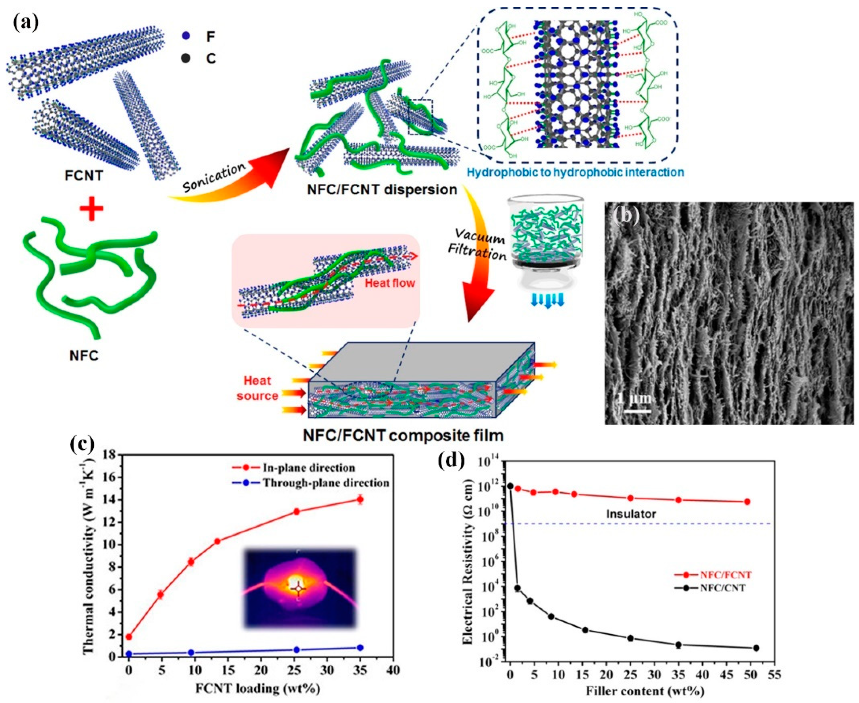
4.1.2. Carbon Nanotubes/Polymer Composites

CNTs are 1-D nanofillers with a perfect hexagonal structure. Their radial dimension is nanometer-level, while the axial dimension is micrometer-level. They can be divided into single-walled carbon nanotubes (SWCNTs) and multi-walled carbon nanotubes (MWCNTs), which are very popular thermally conductive fillers with λ of 2000 and 3000 W/m·K, respectively.
Wang et al. [123] prepared barium titanate@super short MWCNTs (BT@SSCNT) core–shell particle core–shell particles in a closed reaction space (as shown in Figure 6a). Then, BT@SSCNT/PVDF composite flexible films with excellent thermal and dielectric properties were prepared by solution mixing. BT@SSCNT/PVDF composite films showed an excellent λ of 25.43 W/m·K and superior dielectric properties (as shown in Figure 6b,c). Xie et al. [124] prepared MWCNT@BNNS/epoxy nanocomposites via functionalized surface treatment of MWCNT and BNNS to construct a three-dimensional thermal conductivity network (as shown in Figure 7a). The highest λ of the MWCNT@BNNS/epoxy nanocomposites could reach 1.92 W/m·K and showed excellent dielectric properties (as shown in Figure 7b,c). Due to the excellent electrical conductivity of CNTs, its application in the field of insulation is limited. In order to coordinate the electrical conductivity and λ of CNTs, Wang et al. [125] used fluorinated carbon nanotubes (FCNTs) with insulating properties as thermally conductive fillers to prepare nano-fibrillated cellulose (NFC) composites film via vacuum-assisted filtration (as shown in Figure 8a). The NFC/FCNTs composites film was a layered structure, with a prominent λ of 14.1 W/m·K and favorable electrical insulation properties with 21 wt.% FCNTs (as shown in Figure 8b–d). Table 3 shows the λ of carbon nanotubes/polymer composites.

4.1.3. Carbon Fiber/Polymer Composites

Carbon fiber is a high-strength, high-modulus 1-D nanofiller with a carbon content of more than 90%, which has excellent high-temperature resistance, friction resistance, and electrical and thermal conductivity. Its main purpose is combining with resins, metals, ceramics, etc. to prepare advanced composites as reinforcing material. The λ of carbon fiber can reach 100 W/m·K. It is widely used in the preparation of TCPCs.
He et al. [131] prepared PDMS/short-carbon-fiber (SCF) composites via the spatial confining forced network assembly (SCFNA) method (as shown in Figure 9a). The PDMS/SCF composites with an SCF content of 18 wt.% and thickness of 0.1 mm indicated a favorable λ of 2.952 W/m·K and outstanding electrical properties (as shown in Figure 9b–d). Zhang et al. [132] proposed a conversion method from a “sand-like” to “stone-like” conductive network to prepared PDMS/SCF/glass bubbles (GB) composites via SCFNA and adding glass bubbles (as shown in Figure 10a). The effect of rigid particles reduced heat dissipation and played the role of the volume exclusion effect. The results show that the maximum λ of the PDMS/SCF/GB could reach 11.69 W/m·K with 30 wt.% SCF and 2 wt.% GB; meanwhile, it possessed superior mechanical properties (as shown in Figure 10b,c). The thermal dissipation of “stone-like” thermally conductive networks (Qstone) was much lower than that of the “sand-like” thermally conductive networks (Qsand) (as shown in Figure 10d). Wang et al. [133] prepared epoxy/CF/Al2O3 composites via a facile method that infiltrated epoxy resin into the CF/Al2O3 framework that was prepared by blending. This CF/Al2O3 framework could effectively reduce the interfacial thermal resistance between the matrices and the CF (as shown in Figure 11a). Epoxy/CF/Al2O3 λ could reach 3.84 W/m·K with the 6.4 wt.% CF and 74 wt.% Al2O3, which increased by 2096.6% compared with the pure epoxy (as shown in Figure 11b,c). Table 4 shows the λ of carbon fiber/polymer composites.

4.2. Inorganic Fillers/Polymer Composites

Inorganic thermally conductive fillers usually have high λ and electrical insulation properties, and they are mainly used to prepare thermally conductive insulating composites. Commonly used inorganic fillers are BN, AlN, SiC, Al2O3, Si3N4, and so on. The λ of boron nitride is much higher than other inorganic fillers.

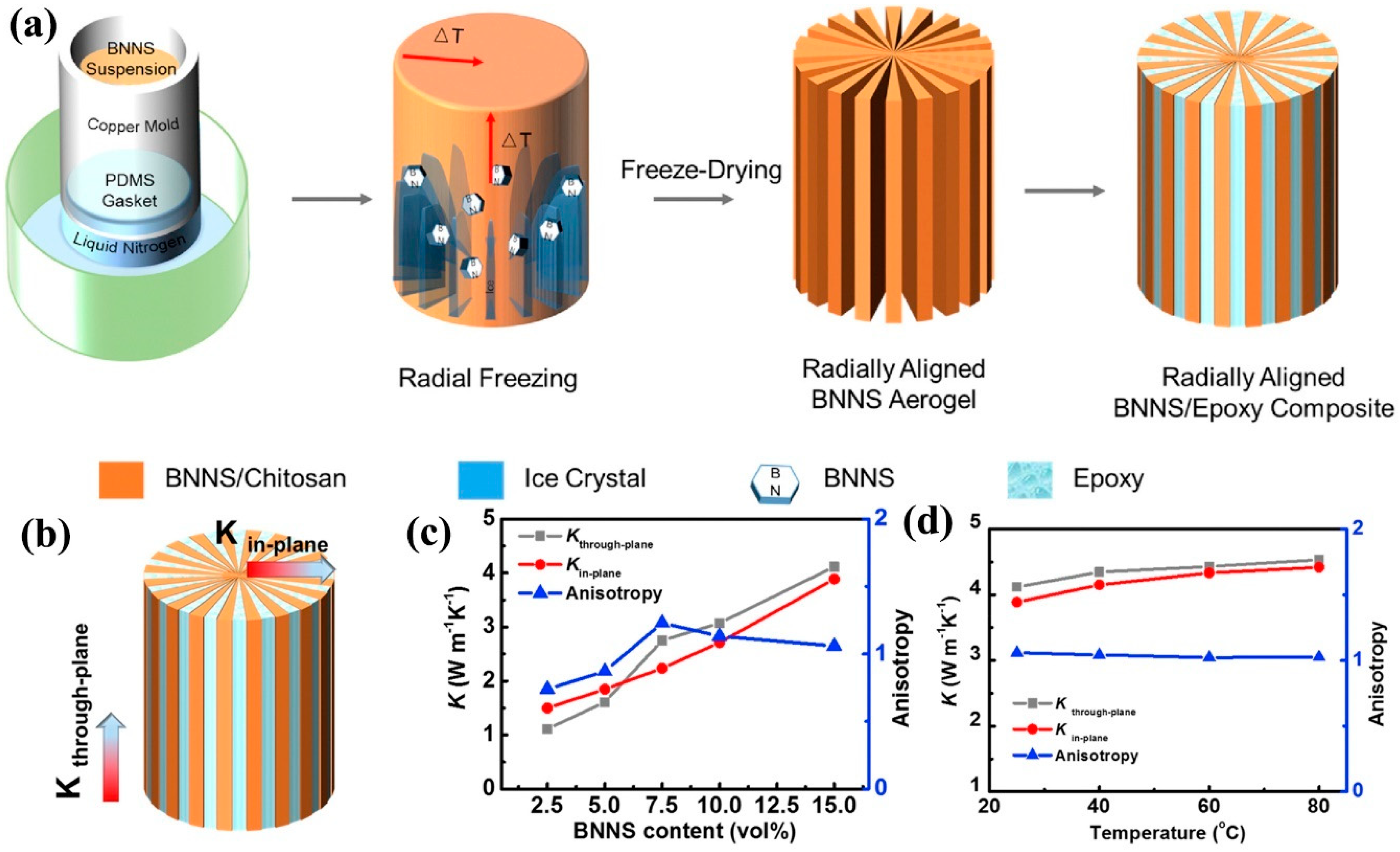
4.2.1. Boron Nitrides/Polymer Composites

BN is a mixture of boron and nitrogen, a crystal composed of nitrogen atoms and boron atoms, with a chemical composition of 43.6% boron and 56.4% nitrogen. It has prominent lubrication and abrasion properties, and high thermal conductivity and electrical insulation. Different arrangements of boron and nitrogen atoms produce different structures. Among various forms of BN, h-BN has recently attracted widespread attention due to its good heat dissipation capability. It can be compared with graphene used to prepare TMMs. The h-BN can also be processed by chemical treatment, heat treatment, mechanical treatment, and ultrasonic treatment to facilitate exfoliated h-BN, in order to obtain a single layer or several layers of BNNS connected by van der Waals forces. The in-plane λ of h-BN can reach 400 W/m·K, while the λ of exfoliated BNNS can reach 1600–2000 W/m·K [140]. Due to the outstanding properties of BN, many researchers are dedicated to the preparation of BN/polymer composites.
Chen et al. [27] prepared the BN-poly (vinylidene difluoride) (PVDF) scaffold by the salt template method using PVDF as the adhesive, and manufactured the corresponding epoxy composites via vacuum-assisted impregnation (as shown in Figure 12a). The epoxy/BN-PVDF composites exhibited a high λ of 1.227 W/m·K at an BN content of 35 wt.%, contributed by the constructed BN pathway held together by PVDF adhesive (as shown in Figure 12b,c). Ma et al. [141] prepared polydopamine-functionalized boron nitride nanosheet (BNNS@PDA)/aramid nanofiber (ANF) thermally conductive composites papers with nacre-mimetic layered structures through vacuum-assisted filtration and hot pressing (as shown in Figure 13a). Figure 13b shows the optical picture of the product. Figure 13d shows the layered structures of sample, and the in-plane λ of the 50 wt.% BNNS@PDA/ANF composites papers reached 3.94 W/m·K. Meanwhile, the composites had excellent mechanical properties and outstanding thermal stability that the tensile strength reached 36.8 MPa and the heat resistance index (THRI) attained 223.1 °C (as shown in Figure 13e). Zhao et al. [94] reported a new method to effectively improve the λ of epoxy composites by the micro-nano coordination effect. They used the liquid exfoliation method to prepare BNNS and the solution blending and curing process to prepare BNNSs/boron nitride microspheres (BNMSs)/epoxy composites, constructing a three-dimensional thermally conductive network with nanoscale 2D BNNSs, as shown in Figure 14a,d. The BNNSs/BNMSs/epoxy composites with a filler loading of 30 wt.% showed a prominent λ of 1.148 W/m·K and outstanding electrical insulation properties (as shown in Figure 14b,c). Huang et al. [142] reported a novel radially aligned three-dimensional boron nitride nanosheets (BNNS)/epoxy composite via the radial freeze-casting method (as shown in Figure 15a). The radially aligned BNNS/epoxy composite exhibits bidirectional high thermal conductivity, with 4.02 W/m·K in the through-plane direction and 3.87 W/m·K in the in-plane direction at a BNNS content of 15 vol.% (as shown in Figure 15b,c). Meanwhile, the change in thermal conductivity of BNNS/epoxy composites with temperature is shown in Figure 15d. Table 5 shows the λ of boron nitride/polymer composites.

4.2.2. Other Inorganic Filler/Polymer Composites

Although the performance of other inorganic fillers (SiN, SiC, Al2O3, Si3N4, etc.) is not as good as that of BN, they are also one of the important fillers used to prepare thermally conductive and insulating composites.
Ouyang et al. [79] used high-frequency thermal plasma to treat Al2O3 nanospheres as thermally conductive fillers to prepare Al2O3/silicon rubber (SR) composites (as shown in Figure 16a,b). The Al2O3/SR composites possessed a superior λ of 1.53 W/m·K and volume resistivity (as shown in Figure 16c,d). Meanwhile, the Al2O3/SR composites also exhibited good dielectric properties, outstanding mechanical properties, and thermal stability. Han et al. [153] prepared novel hetero-structured silicon carbide-boron nitride nanosheets (SiC-BNNS) as thermally conductive and insulating fillers through sol–gel and in-situ growth methods, and they prepared the SiC-BNNS/epoxy thermally conductive nanocomposites by the blending-casting approach (as shown in Figure 17a). Figure 17b shows the SEM images of hetero-structured SiC-BNNS with different ratios. Obviously, SiC grew on the surface of BNNSs. The SiC-BNNS/epoxy composites with a filler loading of 20 wt.% showed a favorable λ of 0.89 W/m·K in Figure 17d and excellent breakdown strength and the electrical insulating properties in Figure 17e,f, respectively. Wu et al. [154] introduced a kind of reticulated porous alumina ceramics (RPCs) into EP doped with tetrapod-like zinc oxide whiskers (T-ZnOw) to produce EP/Al2O3/T-ZnOw composites with a continuous interpenetrating network structure (as shown in Figure 18a). Figure 18b shows the typical images of the reticulated porous ceramics (left) and processed samples (right). The EP/Al2O3/T-ZnOw composites showed an excellent λ of 1.968 W/m·K and outstanding mechanical properties (as shown in Figure 18c–e). Table 6 shows the λ of other inorganic fillers/polymer composites.

4.3. Metal Fillers/Polymer Composites

Metal fillers have excellent thermal- and electrical-conductivity properties. For example, the λ of silver, copper, and aluminum can reach 430 [81,82], 350–400 [58,84], and 234 W/m·K [86], respectively. They can be used to prepare TCPCs with outstanding EMI SE performance.
Xu et al. [58] fabricated a unique 3D interconnected Cu network to enhance the thermal conductivity properties of epoxy composites. They used Carbon felt (CFelt) as a 3D skeleton, and electroplated Cu on the surface of CFelt to construct the 3D Cu film network, which can serve as a continuous heat conduction path (as shown in Figure 19a). Figure 19b shows the heat conduction in the CFelt/epoxy and Cu-CFelt/epoxy composites. The Cu-CFelt/epoxy composites with the Cu content of 30 wt.% showed an ultrahigh λ of 30.69 W/m·K, which was nearly 140 times higher than that of pure epoxy (as shown in Figure 19c). Additionally, the Cu-CFelt/epoxy composites maintained excellent mechanical properties and presented superior electrical conductivity of 7.49 × 10⁴ S/cm. Ji et al. [165] prepared MXene/Ag aerogels via combining the ice-templating and freeze-drying methods. They prepared MXene/Ag-epoxy nanocomposites films by vacuum-assisted penetration (as shown in Figure 20a). Figure 20b shows 3-D networks and the heat transfer model, where Ag nanoparticles fell on the surface of MXene, reducing the contact resistance between individual MXene nanosheets. In Figure 20c, MXene/Ag-epoxy nanocomposites films possessed an excellent through-plane λ of 2.65 W/m·K with a relatively low loading of 15.1 vol.%. Chang et al. [86] used a plasma-enhanced CVD process to grow uniform and dense carbon nanotubes (CNT) on the surface of graphite film (GF). The synthesized carbon nanotubes can act as a bridge between GF and Al to enhance the interface performance and improve the thermal performance of GF/Al laminate composites. As a result, layer-by-layer CNTs-GF/Al composites that are manufactured can enhance the mechanical properties and thermal management capabilities (as shown in Figure 21a). The CNTs-GF/Al composites showed an ultrahigh in-plane λ of 1042 W/m·K and through-plane λ of 47 W/m·K (as shown in Figure 21b). Table 7 shows the λ of metal fillers/polymer composites.

5. Theoretical Models for Thermally Conductive Polymers Composites

Many professors have obtained many theoretical models when studying the thermal conduction theory of polymer composites. In this way, the thermophysical properties of composites can be better-understood and logical prediction results can be given [170]. The following is a brief introduction to several major theoretical models and their merits and limitations.

5.1. Maxwell–Eucken Model

The model is based on the Maxwell utilization of potential theory. It assumes that all the fillers are clustered at the center of the cube block of the composites, thus obtaining precise solutions for the conductivity of randomly distributed and noninteracting spheres in homogeneous media. Eucken replaced electrical conductivity with thermal conductivity to attain the thermal conductivity model of an interaction-free homogeneous sphere randomly distributed in homogeneous matrices. This model is presented as follows [171,172,173]:
λ = λ m [ λ f + 2 λ m + 2 V f ( λ f λ m ) λ f + 2 λ m 2 V f ( λ f λ m ) ]
where λ m is the thermal conductivity of the matrices, λ f is the thermal conductivity of the filler particles, and V f represents the volume fraction of the fillers (the same below). The model is only applicable to the low content of fillers in composites. That is to say, the theoretical curve of the Maxwell–Eucken model is close to the experimental data when the filling content is low. The difference between them is obvious when the filling amount is high. Therefore, when using this model, we must pay attention to satisfying the prerequisite conditions of Maxwell’s equation: Low particle content, isolated existence, and no interaction.

5.2. Hasselman–Johnson Model

To figure out the model problems existing in the Maxwell–Eucken model, the Hasselman–Johnson (H–J) model is proposed to develop the Maxwell–Eucken model and introduces the effects of two-phase interfaces of composites [174]. The H–J model is widely used to analyze and forecast the λ of particle-reinforced composites [175,176]. The H–J expression of the theoretical model is:
λ = λ f [ 2 λ f + λ m e f f + 2 ( λ m e f f λ f ) V f ] 2 λ f + λ m e f f ( λ m e f f λ f ) V f
λ m e f f = λ m 1 + λ m h · r
where r represents the radius of the spherical particles in the reinforced phase, h expresses the interfacial thermal conductance of the composites, and λ m e f f is the effective λ of the fillers in the reinforced phase. The H–J theoretical model has been widely used in the research area of particle-reinforced composites, especially in the specific two-phase interface structure of composites. However, the H–J model has some disadvantages similar to the above model. Under the condition of lower particle content in the second phase, the H–J theoretical model is more consistent with the experimental results and has better applicability.

5.3. Bruggeman Model

Bruggeman [177] has established a relationship between the λ of granular materials in the continuous phase. This model is also the expansion to the Maxwell–Eucken model. When the volume fraction of filler particles is high and the distance between particles is small, the interaction between particles should be considered. Based on the Bruggeman integral embedding principle, the equation of thermal conductivity is derived:
1 V f = λ f λ λ f λ m ( λ m λ ) 1 / 3
The model is suitable for predicting high-thermal-conductivity filler content and particle interaction, and the experimental data are consistent with the theoretical curve of the model.

5.4. Hamilton–Crosser Model

Hamilton [178] thought the geometry of the reinforcements was also related to the λ of the composites. It is assumed that a model is a heterogeneous system consisting of a continuous phase and a dispersed phase. Particles of different shapes are randomly dispersed in the continuous phase. Based on this conjecture, he derived a general TCPC model:
λ = λ m [ λ f + ( n 1 ) λ m + ( n 1 ) V f ( λ f λ m ) λ f + ( n 1 ) λ m V f ( λ f λ m ) ]
where n = ψ/3 and ψ is the sphericity of the thermal fillers. Sphericity is defined as the ratio of the surface area of a sphere with the same volume as the object to the surface area of the object. If the thermal conduction fillers are spherical, ψ = 1, n = 3. This model studies the relationship between the λ of heterogeneous two-component mixtures and the composition, λ of the pure components, and the shape of particles.

5.5. Parallel and Series Model

The simplest mixed-rule models are the parallel model and series model [179]. The parallel and series models are shown in Figure 22.
Parallel models:
λ = ( 1 V f ) λ m + V f λ f
Series models:
λ = 1 ( 1 V f ) λ m + V f λ f = λ m λ f λ f ( 1 V f ) + λ m λ f
The prediction of extreme λ by the parallel and series model is based on the conductivity theory of parallel and series circuits. The parallel model and series model are usually the maximum and the minimum extreme value of composites in the two-component system, respectively.

5.6. Agari Model

Agari [180] proposed a new thermal conduction model, which discussed the λ of polymer composites with different filler types added to the matrices. The previous two-phase system model proposed by most people only discussed the λ of a single-filler polymer. This model can predict well the λ of composites when the thermal particles contact each other and form thermal-conductivity networks under the condition of high filler content.
The parallel and series models proposed above can be regarded as two extreme model systems, and the actual λ of the composite exists between the two models. The λ of multicomponent (multiphase) composites in parallel and series models can be estimated by the following equation respectively:
Multiphase parallel conduction:
λ = V 1 · λ 1 + V 2 · λ 2 + V 3 · λ 3 +
Multiphase series conduction:
1 λ = V 1 λ 1 + V 2 λ 2 + V 3 λ 3 +
where λ1 is the thermal conductivity of a polymer; λ2, λ3, λ1, etc. represent the thermal conductivities of fillers 2, 3, 4, etc., respectively; V 1 is the volume content of the polymer; V 2 , V 3 , V 4 , etc. represent the volume content of fillers 2, 3, 4, etc.; and V 1 + V 2 + V 3 + V 4 = 1.
Considering the heat conduction chain formed by the interaction of particles, the shape and relative content of particles, and other factors, the following equation is obtained [172,181,182]:
log k = V 1 · log ( C 1 k 1 ) + V 2 · C 2 · log k 2 + V 3 · C 3 · log k 3 +
where C1 represents the influence factor of the crystallinity and crystal size of the polymer; and C2, C3, C4, etc. represent the difficulty of forming the thermal conductivity chain.
For different theoretical models, the factors affecting the λ of composites are also distinguishable. It mainly includes the λ of the fillers and the matrices itself, the content of the fillers, the size and morphology of the fillers, and the interaction between the fillers and the matrices. The theoretical model proposed at present is not perfect enough to fully reflect the thermal conduction mechanism of composites, so researchers need to constantly revise and innovate the theoretical model based on experiments. Table 8 gives a brief summary of the characteristics of various models.

5.7. New Development of Thermal Conductivity Models for Polymer-Based Composites

In recent years, the thermal conductivity model of polymer-based composites has developed rapidly, and the influence of other factors has been further studied on the basis of predecessors. Shimizu et al. [183], in their study on refractory brick, reduced λ by increasing porosity, and explored the thermal conductivity model of high-porosity alumina refractory brick. The results show that the porous refractory was strongly affected by thermal radiation when the temperature was higher than 783 K. In addition, the higher the temperature, the higher the λ, while the λ of alumina decreased with temperature. The specific expression is as follows:
λ = 1 3 · λ f · ( 1 P ) + λ a i r · P 1 3 + 2 3 × 0.1942 · ε · ( T 300 ) 3 D p · P 1 3
where ε is the heat diffusion coefficient, Dp is the average pore diameter, T is the temperature, and P is the porosity. The model takes into account the effects of porosity, temperature, pore diameter, and other parameters, and better-describes the effects of convection and radiation on the heat conduction process.
Drozdov [184] provides a model for the λ of highly filled composites. The specific expression is as follows:
d X d φ = 1 1 φ [ 1 3 R 1 ( 1 Λ ) + B Λ ( R 2 X ) X ) R 2 + ( B 1 ) X ]
where X(0) = 1; X = λ/λm; Λ represents the volume fraction of particles aggregated into finite clusters; B is how the shape of separated particles and their finite clusters deviate from the spherical; R1 and R2 are the ratios of the effective thermal conductivities of fillers λf1 and λf2, respectively, to the thermal conductivity of matrix λm; and ϕ denotes the volume fractions of particles. The model takes into account the agglomeration of filler particles, the formation of the thermal conduction network, and the thermal resistance at the interface between matrix and fillers.

6. Simulations of Thermally Conductive Polymers Composites

TCPCs were prepared by diverse methods with higher λ. Their mechanisms of the heat dissipation or heat generation were simulated by various simulation software. It is extremely necessary to do these simulations, which can be compared with the experimental results to further testify that the thermally conductive composites prepared have excellent thermal management ability. Consequently, researchers have been inclined to add simulation content to the results and discussion in the paper. There are numerous simulation methods, and this review focuses on the molecular dynamics simulation and ANSYS finite element analysis of TCPCs.

6.1. Molecular Dynamics Simulation

In recent years, scientists have gradually studied the heat transfer problem at the micro scale. In this case, the applicability of the classical theory of heat transfer will be not suitable. Researchers urgently need to put forward some new theories to analyze the micro-scale heat transfer problem [185]. With the rapid development of microelectronics, nanochip, and nanoscience, the size of devices tends to be miniaturized gradually. The scientists studied heat transfer, which was based on a spatial scale of nanometers and a time scale of 10–15 fs. These issues need to be analyzed at the molecular and atomic levels [186]. The molecular dynamics (MD) method is a computer simulation method that treats the molecules/atoms in the system as classical particles and studies their properties from the perspective of statistical mechanics [186,187].
The basic principle of the MD method is to solve the problem of the interaction potential between specific molecules/atoms in the system and the Newton equation of motion for molecules/atoms with system external constraints. Then, the microscopic process of the system evolution over time is simulated and the equilibrium parameters and transport properties of the system are calculated statistically. Thermal conductivity is an important parameter to control the heat conduction of micro-scale systems, especially solid materials. At the micro-scale, MD simulation can better-predict the λ of composites. It can be mutually verified with experimental results to increase the reliability of the experiment. MD can be roughly divided into two types, equilibrium molecular dynamics (EMD) and nonequilibrium molecular dynamics (NEMD).
EMD method for thermal conductivity. The EMD is a Green–Kubo equation based on the fluctuation dissipation theorem and linear response theory [188]. The correlation function of heat flow at the microcosmic scale is related to the heat transfer coefficient of the equilibrium state by the Green–Kubo equation [189]. The thermal conductivity in EMD can be defined as:
λ = V 3 k B T 2 j ( 0 ) j ( t ) d t
where V represents the volume, k B represents the Boltzmann constant, T is the temperature of the system, j is the heat flow, and 〈〉 is the average time of the ensemble. j heat flow is also calculated as:
j = 1 V [ I E i v i I S i v i ]
where E i shows the total energy of atom i, v i shows the velocity, and S i is the symmetric stress tensor of atom i.
NEMD method for thermal conductivity. NEMD is usually applied to foretell the λ of composites [190]. The thermal conductivity in NEMD is defined as:
G = Q ˙ A T
where Q ˙ represents heat flow, A represents interfacial area, and T is the temperature difference. The flux in the system produces an unbalanced temperature distribution, which is derived from the average kinetic energy of the atoms in all the plates. The equation is expressed as:
T J = 1 3 k B N S i S j m v i 2
where T J represents the temperature of the j plate, N S is the number of atoms in a plate, m represents the mass, and v i is the instantaneous velocity of the atom i.
Yao et al. [191] reported that a three-dimensional (3D BN-SiC) framework was prepared by the combination of ice template assembly and high-temperature sintering. The intrinsic mechanism of microscopic enhanced heat transfer after sintering was revealed by MD. Figure 23a shows a schematic diagram of the sintered BN/SiC junction, which indicates the presence of a certain number of Si-C, B-C, and Si-N keys near the boundary that connect two separate BN plates. In Figure 23b, it indicates that the energy injected into (removes from) the heat sink (heat source) changed over time. The slope of the curve indicates heat flux Q. It is obvious that the heat flux of 50% sintering was lower than that of 100% sintering. Figure 23c expresses the temperature distribution in the x direction. It can be seen from the figure that 100% sintering and 50% sintering had similar temperature distributions. According to the inference of Equation (13), the equation of the interfacial thermal resistance is as follows:
R = A T /   Q
Thus, R100% = 1.29 × 10⁻⁹ (m2∙K)/W (SiC 100% sintering) and R50% = 2.77 × 10⁻⁹ (m2∙K)/W (SiC 50% sintering). Obviously, the thermal resistance of 50% sintering is higher than that of 100% sintering. Through the analysis of MD simulation results, the composites prepared by 100% sintering had a lower interfacial thermal resistance and improved λ.
Similarly, the Ji et al. [165] team chose to run the MD simulation to verify their results that Ag can increase the λ of the MXene/Ag-epoxy composites. The MD simulation was carried out using the large-scale atomic/molecular parallel simulation package [192]. Figure 24a is the schematic of the simulation model of MXene/Ag-epoxy nanocomposites films. In Figure 24a, the fixed Ttop and Tbottom, placed on the upper and lower surfaces, could obtain the effective thermal conductivity by calculating the heat flux from the lower surface to the upper surface. The effect of the influence of Ag particles on thermal interfacial resistance is illustrated by comparing the two examples. In Figure 24d, it shows three MXene layers, whereas in Figure 24e, each MXene layer is connected by Ag. It expresses the energy that injects into (removes from) the heat sink (heat source) changing over time (as shown in Figure 24f). The slope of the curve indicates heat flux Q where the Q of three MXene layers is lower than that of the MXene layer connected by Ag. According to Equation (15), interfacial resistance RMXene = 2.4 × 10⁻⁹ (m2∙K)/W and RMXene-Ag = 2.0 × 10⁻⁹ (m2∙K)/W. According to the simulation results, the composites with the MXene layer connected by Ag had a lower interfacial thermal resistance, which boosted the λ of the composites and enhanced the interfacial heat transport.
Dai et al. [193] mechanically designed a structure named HLGP consisting of the vertical plate in the middle and the horizontal plate cap at the top and bottom. They reported that L-shaped graphene and vertical graphene were analyzed by a NEMD simulation system, simulating HLGP and cap-removed samples, respectively. There are four different cases of analysis and simulation: (a) Vertical graphene, and L-shaped (b) single-layer, (c) bilayer, and (d) tri-layer graphene, in Figure 25. Figure 25a,b show that the effective contact λ was improved by about 3 times (from 7.8 to 22.5 MWm−2K−1). When the number of graphene layers in the horizontal direction increased, λ did not rise. The simulation results show that the effective contact λ was basically independent of the number of graphene layers. The results demonstrate that the horizontally oriented graphene layer on both sides of the HLGP was a key part to achieving low contact thermal resistance.
In addition, Xu et al. [194] explored the thermal conductivity mechanism of SR from three aspects of chain length, morphology, and temperature using nonequilibrium molecular dynamics. SR is a kind of TIM widely used in electronic devices. Through simulation, it was concluded that the thermal conductivity increased obviously with the silicon–oxygen chain length in the crystalline state of chain arrangement, and the λ of crystalline SR with 79 nm length could reach 1.49 W/(m·K).

6.2. Finite Element Modeling (FEM)

The basic ideas of FEM can be traced back to 1909 (Ritz Method [195]) and 1915 (Galiagin Method [196]). The term “finite element” was first used by Clough [196] and developed by Zienkiewicz et al. [197] in the field of numerical methods and civil engineering. Since 1943, the finite element method has been developing continuously in engineering science [198]. This method discretizes large domains into small units and then computes the physical behavior of each unit. In the early stage of finite element, scientists mainly studied the physical behaviors including displacement and stress, which were connected with structural applications. Nevertheless, with the development and growth of advanced computer technology, the FEM has spread to many other fields, such as aerospace engineering design, microelectronic applications, and composites. FEM studying the thermal conductivity of composites is based on the ANSYS finite element program to calculate the λ of composites, and the correlation analysis is carried out with the experimental results.
Yang et al. [199] used a finite volume simulation based on ANSYS Fluent to prove that the natural rubber (NR)/reduced graphene oxide (rGO) films prepared had favorable thermal management ability, such as heat dissipation and heat generation performance. Two cases of heat generation and heat dissipation of the fabricated films were studied. In case 1 (as shown in Figure 26c), the upper chip in the model (as shown in Figure 26a,b) was set as a heat source and the bottom prepared films were used as TMMs to analyze heat dissipation performance. On the contrary, the bottom of the TMMs was used as a heat source to analyze the heat generation performance in case 2 (as shown in Figure 26f). Obviously, the final equilibrium temperature of the chip using the anisotropic TMMs prepared was lower than that of other isotropic TMMs with different λ (as shown in Figure 26d). At the same time, the heat transfer rate of the prepared anisotropic TMMs was higher than that of other isotropic TMMs (as shown in Figure 26e). The simulation results in Figure 26g shows that when the anisotropic films prepared were used as TMMs, the average temperature of the chip increased rapidly, compared with other isotropic TMMs. Through these two simulation cases, it can be proved that the TMMs prepared had good thermal management ability and can better-control the temperature of electronic equipment.
An epoxy composite with high λ has been prepared by Feng et al. [94]. The composites use 2D boron nitride nanosheets (BNNSs) and 0D boron nitride microspheres (BNMSs) to construct a 3D thermal conductivity network (as shown in Figure 27a). The internal temperature distributions of BNMSs/epoxy composites and BNNSs/BNMSs/epoxy composites were further simulated by ANSYS finite element analysis. It was proved that BNNS/BNMS played an important role in improving the thermal conductivity of BNNS/BNMS/epoxy composites. In Figure 27c–e, a model of BNMSs with a 40% filler randomly distributed in the epoxy resin matrix was established. Another model for selecting epoxy resin for matrix and BNNSs/BNMs for filler was established and compared with the former, as shown in Figure 27f–h. According to the simulation results, as shown in Figure 27b, the maximum surface temperature of composites BNNSs/BNMSs/epoxy was higher than that of BNMSs/epoxy when the curve reached equilibrium. These simulation results demonstrate that BNNSs and BNMSs can indeed improve the thermal conductivity of BNNS/BNMS/epoxy composites.
Chen’s team [200] selected BNNS as the filler and the polyvinyl alcohol (PVA) as the matrix to fabricate nanocomposites. They used the ANSYS finite element simulation method to analyze the temperature and heat flux distribution of nanocomposites in the heating process, proving that PVA/BNNS nanocomposites have thermal management ability. Figure 28b expresses boundary conditions of the finite element simulation. PVA/BNNS nanocomposites after three different treatments were selected for simulation analysis. As shown in Figure 28a, the interfacial thermal resistance of PVA/BNNS nanocomposites with the overlapping BNNS network was lower than that of the other two conditions. The distribution results of temperature and heat flux in the heating process of the nanocomposites after three different treatments are shown in Figure 28c,d. It is obvious that the maximum surface temperature and heat flux of PVA/BNNS nanocomposites with the overlapping BNNS network were better than the other two conditions. The distribution of temperature and heat flux of nanocomposites during heating was analyzed by finite element simulation, which testified the superiority of PVA/BNNS nanocomposites with the overlapping BNNS network.
Dai’s group [201] prepared graphene hybrid paper (GHP) with λ, which had efficient heat dissipation ability and could act as TIMs, which was further demonstrated by simulation. Figure 29a indicates the ANSYS Icepak system model of TIMs. The prepared GHP was simulated and compared with a commercial thermal pad (5000S35) to obtain different temperature distribution diagrams, as shown in Figure 29b,c. Obviously, when GHP was the TIMs, the final surface temperature of the heater was lower than that of the 5000S35 thermal pad as the TIMs. This was consistent with the experimental verification results, as shown in Figure 29e,f. The simulation results show that GHP can be used as TIMs to meet the heat dissipation requirements of electronic equipment.
Similarly, the thermal analysis of the prepared HLGP was performed by Ji’s group [193] using ANSYS Icepak. The commercial thermal pad (XR-m) was selected for simulation comparison with the prepared HLGP, and the simulation results are shown in Figure 30b. Combined with high λ and low thermal contact resistance (as shown in Figure 30a), the simulated temperature distribution in Figure 30b confirmed the excellent heat transfer performance of HLGP, which can be used as TIMs to satisfy the heat dissipation requirements of electronic equipment.

7. Applications as Thermal Management Materials

In recent years, miniaturization and integration have become the development trend of electronic devices. With the increase in the power of electronic equipment, the heat produced has also increased sharply. Therefore, effective thermal management plays a vital role in the development, performance, and reliability of various electronic devices [202,203,204,205]. Common TMMs including TIMs, heat sink, phase-change materials (PCMs), and so on, can transfer, emit, or store excess heat from electronic devices at high temperatures to prevent the overheating of electronic devices [206,207,208,209,210]. However, with the rapid development of electronic equipment in military, aerospace, computer, and other industries, it is urgent to evolve flexible and multifunctional TMMs with the preeminent temperature control ability of electronic equipment [209,210,211].
With the rise of the fifth-generation mobile network and the increase in power density in the field of electronics, the requirement of heat dissipation has become increasingly high, so the study of the TIMs has become particularly significant [212,213,214]. Nowadays, thermally conductive composites are increasingly more widely used in the TIMs. The metal–oxide–semiconductor field-effect transistor (MOSFET) is the main heating element in the switching power supply. Chen et al. [215] used the prepared oriented BNNSs nanocomposites film as TIMs. The TIMs were between the MOSFET and the heat sink, and the heat generated by MOSFET could then be better-transferred to the heat sink with the help of the TIMs (as shown in Figure 31a). The prepared oriented BNNSs nanocomposites film had excellent thermal management capability. After using the film for a period of time, its equilibrium temperature was only about 65 °C. Compared with commercial silicon pad, randomly dispersed BNNS nanocomposites film, and pure PVDF film, the equilibrium temperature was reduced by 5 °C, 5.5 °C, and 11 °C respectively (as shown in Figure 31b). In the same way, Li’s group [216] also used the composites as TIMs. The CPU overheating problem leads to the problem of computer speed. Therefore, the TIMs were placed between the CPU and the heat sink to remove the excess heat of the CPU and fulfilled the requirements of the equipment (as shown in Figure 31c). As shown in Figure 31d, the prepared composites were used as the BNNS/CNT11% grease. Under the condition of 100% CPU operation, the temperature rose from 34 °C to 41 °C after 5 h of operation with a difference of 7 °C. At the same time, commercial thermal conductivity greases have also been tested under the same operating conditions, with a difference of 10 °C. As a result, the prepared composites can be better-used as the TIMs to realize the heat dissipation of electronic equipment.
Yao’s team [191] put the composites on the CPU and GPU of the IBM T43 ThinkPad (as shown in Figure 32a), replacing two commercial thermal pads, and recorded the temperature changes of the laptop during work. Figure 32b shows the temperature change curve when playing the same video on a laptop using three hot pads. When using the computer for some time, the CPU encapsulation temperature with the BN-SiC/PDMS pad as TIM was 10 °C lower than that of the original thermal pad, and 4 °C lower than that of the 3015 silicone pad. Similarly, Ji et al. [165] applied the MXene/Ag-epoxy nanocomposites to the CPU of a smartphone to fit the heat dissipation requirements of the device (as shown in Figure 32c). As shown in Figure 32d, compared with pure epoxy resin, the MXene/Ag-epoxy nanocomposites as the TIMs had a faster heat dissipation rate. After 25 s of CPU operation, the surface temperature of the MXene/Ag-epoxy nanocomposites reached 80 °C, while the pure epoxy was only 40 °C. The higher the surface temperature of the composites, the more heat was absorbed from the CPU. Therefore, the MXene/Ag−Epoxy nanocomposites had excellent thermal management ability.
Similarly, Dai’s group [202] used the GHP prepared as TIMs on the computer CPU to cool the CPU. Meanwhile, a comparison with commercial TIMs (5000S35 thermal pad) proves the excellent heat dissipation capacity of composites, as shown in the Figure 32e. As shown in Figure 32f, when the CPU was applied with GHP as the TIMs after running for 780 s, the temperature of the CPU was 6.3 °C lower than those of the commercial TIMs. The infrared contrast image of the motherboard was obtained when the 5000S35 thermal pad and GHP were used as TIMs. It is obvious that the CPU surface temperature was lower when the GHP was used as the TIMs.
This section briefly introduces the applications of TIMs, which are used on the CPU of a smartphone or laptop to transfer heat to the fan. In the future, more thermally conductive composites will be used as the TIMs to accord the heat dissipation requirements of electronic equipment.

8. Conclusions and Prospects

In polymer composites, it is a challenging problem to obtain outstanding λ with superior comprehensive properties. By adding thermally conductive filler to a polymer matrix, an excellent thermally conductive pathway can be obtained and the diffusion rate of phonons in the thermal conduction pathway is raised. The thermal management ability of TCPCs is enhanced so that it can be better-used in electronic equipment. Due to the revolutionary advances in nanomaterials and material processing technology, the rapid development of various new thermally conductive fillers has provided many possibilities for the preparation of high-performance polymer composites. In this review, we discuss the thermal conduction mechanism of polymer composites, the factors that influence the λ of polymer composites, and various methods to improve the heat conduction capability of polymer composites. Some theoretical models of thermal conduction systems, different simulation methods for analyzing the heat conduction process, and the application of TMMs are introduced. On this basis, the following main conclusions can be drawn:
  • Phonon transport is the main mechanism of polymer heat conduction. Disordered polymer chains and weak intermolecular interactions can lead to strong phonon scattering and hinder phonon transfer, which is the reason for poor polymer thermal conductivity. Carbon-based fillers, graphite-based fillers, inorganic filler metal fillers, and mixed fillers have high thermal conductivity. It is the most important method to improve the λ of polymer composites to construct the transport path of phonons in the polymer matrix by filling thermal-conductivity fillers.
  • There are many factors that affect the λ of composites, such as the filler types, the size and shape of the filler, the dispersion and distribution of the filler in the matrix, and the content of the filler. Through a variety of physical methods, chemical methods can construct thermal networks to improve the λ of composites in the polymer matrix.
  • According to the different shapes and types of fillers, the theoretical models that can be consistent with the experimental results are proposed. These theoretical models are also slowly maturing. On the basis of these models, composites can be better-analyzed and applied. However, with increasingly more methods to prepare TCPCs and an increasing number of complex types of fillers and substrates, it is necessary to put forward some new and more suitable theoretical models in the future. In addition to the theoretical model, it is essential to establish some various methods to simulate the λ of composites when studying the thermal conduction mechanism and thermal conductivity. Among them, the molecular dynamics model and ANSYS finite element analysis are two commonly used methods. The simulation results are combined with the experimental results to better-analyze the λ and thermal performance of polymer composites.
  • With the advent of the 5G era, and the miniaturization, high power, and high integration of electronic devices, the heat accumulated in the circuit greatly affects their performance and life, so it is very necessary to apply TCPCs to TIMs. The TIMs are used in the CPU of some smartphones or computers to meet the heat dissipation requirements of electronic devices. In the future development of electronic devices, the research of TIMs will be the focus of people’s attention.
According to the research status and development trend of TCPCs, we also need to do the following research:
  • The thermal conduction mechanism of TCPCs is not yet complete. In order to more accurately analyze the reason why thermally conductive fillers form a thermally conductive network in the polymer matrix to increase the λ of composites, more accurate theoretical models need to be established.
  • The influence of interfacial thermal resistance on the λ of composites is deeply studied. The energy transfer and energy dissipation processes in the thermal conductivity of polymer composites are also simulated by combining mathematics, computer, and other related software. The relevant mathematical models are established.
  • The thermal conductivity of intrinsic thermally conductive polymer composites needs further research, such as the study of the effect of molecular chain orientation on thermal conductivity in intrinsic thermally conductive polymer composites.
  • Based on the existing shortcomings in the preparation of TCPCs, more novel, effective, and advanced methods need to be proposed to improve the λ of polymer composites.
  • TCPCs currently prepared in the laboratory have superior λ and are even much better than commercial thermal materials. However, considering cost and process constraints, it is tough to achieve industrial production. Accordingly, we must pay attention to the basic research of TCPCs in industrial applications, and promote the upgrading of industrial products.
It is believed that after overcoming these difficulties, TCPCs will play an irreplaceable role in the fields of military industry, aerospace, artificial intelligence, and microelectronics.

Author Contributions

Writing—original draft preparation, X.Z. and H.Z.; writing—review and editing, Z.F., Y.H., H.X., Y.L., D.W., J.Z. and J.S.; supervision, J.S.; All authors have read and agreed to the published version of the manuscript.

Funding

This research was funded by the National Natural Science Foundation of China (No. 52003019), the Beijing Municipal Natural Science Foundation (No. 2204090), and the Talents Introduction Project in Beijing University of Chemical Technology (No. buctrc201909).

Conflicts of Interest

The authors declare no conflict of interest.

References

  1. Kang, J.S.; Li, M.; Wu, H.; Nguyen, H.; Hu, Y. Experimental observation of high thermal conductivity in boron arsenide. Science 2018, 361, 575–578. [Google Scholar] [CrossRef] [PubMed] [Green Version]
  2. Song, N.; Hou, X.; Chen, L.; Cui, S.; Shi, L.; Ding, P. A Green Plastic Constructed from Cellulose and Functionalized Graphene with High Thermal Conductivity. ACS Appl. Mater. Interfaces 2017, 9, 17914–17922. [Google Scholar] [CrossRef] [PubMed]
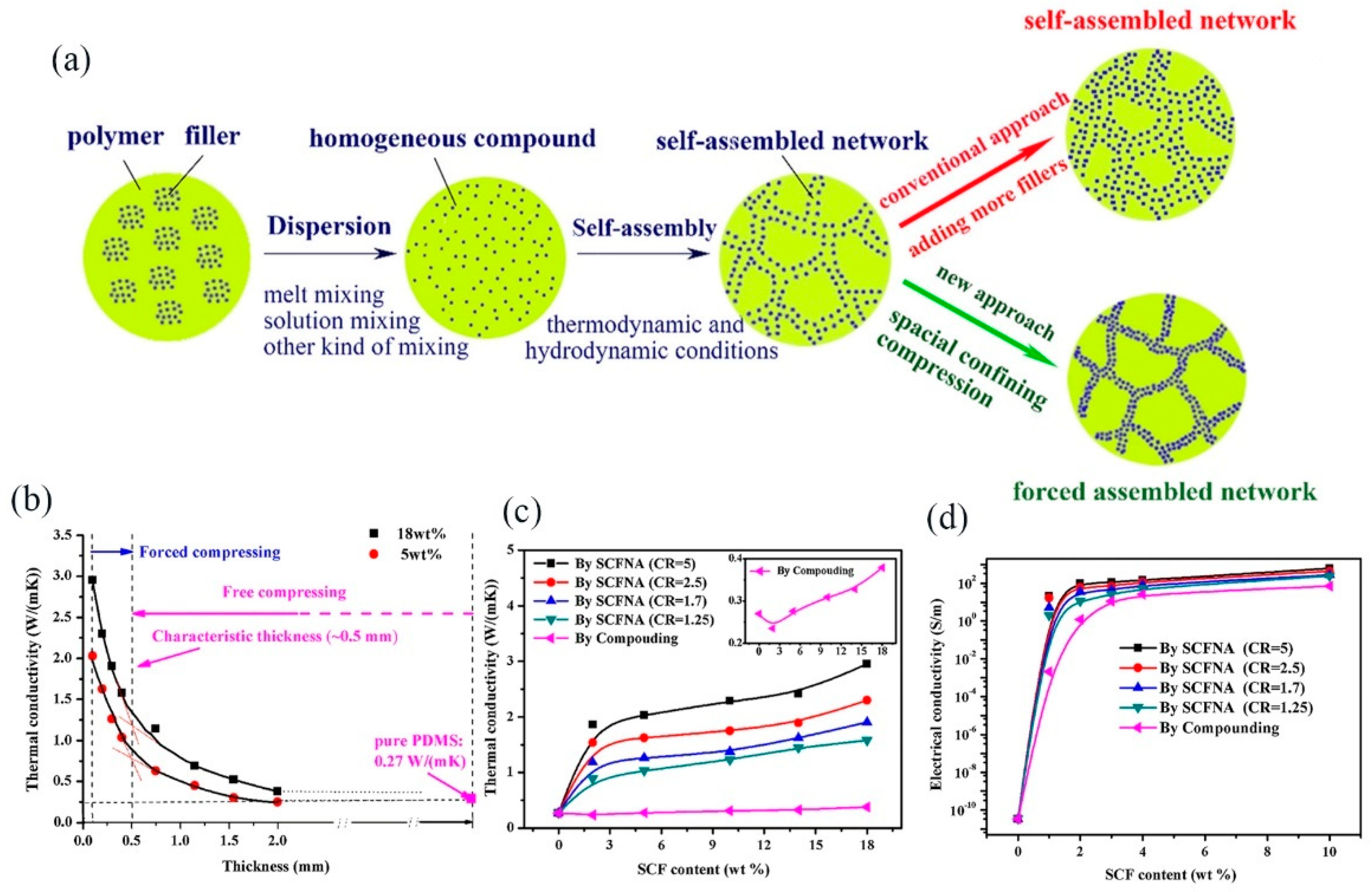
  3. Wang, S.; Liu, Y.; Guo, Y.; Lu, Y.; Huang, Y.; Xu, H.; Wu, D.; Sun, J. Optimal analysis for thermal conductivity variation of EVA/SCF composites prepared by spatial confining forced network assembly. Mater. Today Commun. 2020, 25, 101206. [Google Scholar] [CrossRef]
  4. Sun, J.; Zhuang, J.; Jiang, H.; Huang, Y.; Zheng, X.; Liu, Y.; Wu, D. Thermal dissipation performance of metal-polymer composite heat exchanger with V-shape microgrooves: A numerical and experimental study. Appl. Therm. Eng. 2017, 121, 492–500. [Google Scholar] [CrossRef]
  5. Li, S.; Zheng, Q.; Lv, Y.; Liu, X.; Wang, X.; Huang, P.Y.; Cahill, D.G.; Lv, B. High thermal conductivity in cubic boron arsenide crystals. Science 2018, 361, 579–581. [Google Scholar] [CrossRef] [PubMed] [Green Version]
  6. Tian, F.; Ren, Z. High Thermal Conductivity in Boron Arsenide: From Prediction to Reality. Angew. Chem. Int. Ed. 2019, 58, 5824–5831. [Google Scholar] [CrossRef] [PubMed]
  7. Lin, M.; Li, Y.; Xu, K.; Ou, Y.; Su, L.; Feng, X.; Li, J.; Qi, H.; Liu, D. Thermally conductive nanostructured, aramid dielectric composite films with boron nitride nanosheets. Compos. Sci. Technol. 2019, 175, 85–91. [Google Scholar] [CrossRef]
  8. Zhang, S.; Tian, Y.; Gu, X.; Tangb, W.; Sun, J. Improving the flame resistance and thermal conductivity of ethylene-vinyl acetate composites by incorporating hexachlorocyclotriphosphazene-modified graphite and carbon nanotubes. Polym. Compos. 2018, 39, E891–E901. [Google Scholar] [CrossRef]
  9. Sun, J.; Zhuang, J.; Shi, J.; Kormakov, S.; Liu, Y.; Yang, Z.; Wu, D. Highly elastic and ultrathin nanopaper-based nanocomposites with superior electric and thermal characteristics. J. Mater. Sci. 2019, 54, 8436–8449. [Google Scholar] [CrossRef]
  10. Si, W.; Sun, J.; He, X.; Huang, Y.; Zhuang, J.; Zhang, J.; Murugadoss, V.; Fan, J.; Wu, D.; Guo, Z. Enhancing thermal conductivity via conductive network conversion from high to low thermal dissipation in polydimethylsiloxane composites. J. Mater. Chem. C 2020, 8, 3463–3475. [Google Scholar] [CrossRef]
  11. Zhuang, J.; Hu, W.; Fan, Y.; Sun, J.; He, X.; Xu, H.; Huang, Y.; Wu, D. Fabrication and testing of metal/polymer microstructure heat exchangers based on micro embossed molding method. Microsyst. Technol. 2018, 25, 381–388. [Google Scholar] [CrossRef]
  12. Song, N.; Jiao, D.; Cui, S.; Hou, X.; Ding, P.; Shi, L. Highly Anisotropic Thermal Conductivity of Layer-by-Layer Assembled Nanofibrillated Cellulose/Graphene Nanosheets Hybrid Films for Thermal Management. ACS Appl. Mater. Interfaces 2017, 9, 2924–2932. [Google Scholar] [CrossRef] [PubMed]
  13. Lule, Z.; Kim, J. Thermally conductive and highly rigid polylactic acid (PLA) hybrid composite filled with surface treated alumina/nano-sized aluminum nitride. Compos. Part A Appl. Sci. Manuf. 2019, 124, 105506. [Google Scholar] [CrossRef]
  14. Dong, P.; Long, C.; Peng, Y.; Peng, X.; Du, Y. Effect of coatings on thermal conductivity and tribological properties of aluminum foam/polyoxymethylene interpenetrating composites. J. Mater. Sci. 2019, 54, 13135–13146. [Google Scholar] [CrossRef]
  15. Li, Y.; Tian, X.; Yang, W.; Li, Q.; Hou, L.; Zhu, Z.; Tang, Y.; Wang, M.; Zhang, B.; Pan, T.; et al. Dielectric composite reinforced by in-situ growth of carbon nanotubes on boron nitride nanosheets with high thermal conductivity and mechanical strength. Chem. Eng. J. 2019, 358, 718–724. [Google Scholar] [CrossRef]
  16. Yang, C.-R.; Chen, C.-D.; Cheng, C.; Shi, W.-H.; Chen, P.-H.; Teng, T.-P. Thermal conductivity enhancement of AlN/PDMS composites using atmospheric plasma modification techniques. Int. J. Therm. Sci. 2020, 155, 106431. [Google Scholar] [CrossRef]
  17. You, J.; Choi, H.-H.; Lee, Y.M.; Cho, J.; Park, M.; Lee, S.-S.; Lee, J. Plasma-assisted mechanochemistry to produce polyamide/boron nitride nanocomposites with high thermal conductivities and mechanical properties. Compos. Part B Eng. 2019, 164, 710–719. [Google Scholar] [CrossRef]
  18. Hou, X.; Chen, Y.; Lv, L.; Dai, W.; Zhao, S.; Wang, Z.; Fu, L.; Lin, C.-T.; Jiang, N.; Yu, J. High-Thermal-Transport-Channel Construction within Flexible Composites via the Welding of Boron Nitride Nanosheets. ACS Appl. Nano Mater. 2019, 2, 360–368. [Google Scholar] [CrossRef]
  19. Li, Z.-M.; Wang, Z.-G.; Yin, H.-M.; Xu, J.-Z.; Chen, Y.; Lei, J.; Zhu, L.; Gong, F.; Li, Z.-M. Highly Anisotropic, Thermally Conductive, and Mechanically Strong Polymer Composites with Nacre-like Structure for Thermal Management Applications. ACS Appl. Nano Mater. 2018, 1, 3312–3320. [Google Scholar] [CrossRef]
  20. Yu, B.; Xing, W.; Guo, W.; Qiu, S.; Wang, X.; Lo, S.; Hu, Y. Thermal exfoliation of hexagonal boron nitride for effective enhancements on thermal stability, flame retardancy and smoke suppression of epoxy resin nanocomposites via sol–gel process. J. Mater. Chem. A 2016, 4, 7330–7340. [Google Scholar] [CrossRef]
  21. Wang, Z.-G.; Li, Z.-M.; Zhang, G.; Wang, H.-Q.; Xu, J.-Z.; Lei, J.; Zhu, L.; Gong, F.; Li, Z.-M. Enhanced Thermal Conductivity of Segregated Poly(vinylidene fluoride) Composites via Forming Hybrid Conductive Network of Boron Nitride and Carbon Nanotubes. Ind. Eng. Chem. Res. 2018, 57, 10391–10397. [Google Scholar] [CrossRef]
  22. Sun, J.; Zhuang, J.; Liu, Y.; Xu, H.; Horne, J.; Wujcik, E.K.; Liu, H.; Ryu, J.E.; Wu, D.; Guo, Z.; et al. Development and Application of Hot Embossing in Polymer Processing: A Review. ES Mater. Manuf. 2019, 3–17. [Google Scholar] [CrossRef]
  23. Sun, J.; Wu, D.; Liu, Y.; Dai, L.; Jiang, C. Numerical simulation and experimental study of filling process of micro prism by isothermal hot embossing in solid-like state. Adv. Polym. Technol. 2018, 37, 1581–1591. [Google Scholar] [CrossRef]
  24. Wu, D.; Sun, J.; Liu, Y.; Zheng, X.; Xu, H.; Zhao, Z. Novel Method for Injection Molding of High-Performance Electricity-Conductive or Thermal-Conductive Polymer-Matrix Composites Products. CN Patent 106,827,428, 13 June 2017. [Google Scholar]
  25. Wu, D.; Sun, J.; Liu, Y.; Yang, Z.; Xu, H.; Zheng, X.; Gou, P. Rapid fabrication of microstructure on PMMA substrate by the plate to plate Transition-Spanning isothermal hot embossing method nearby glass transition temperature. Polym. Eng. Sci. 2016, 57, 268–274. [Google Scholar] [CrossRef]
  26. Wu, D.; Gao, X.; Sun, J.; Wu, D.; Liu, Y.; Kormakov, S.; Zheng, X.; Wu, L.; Huang, Y.; Guo, Z. Spatial Confining Forced Network Assembly for preparation of high-performance conductive polymeric composites. Compos. Part A Appl. Sci. Manuf. 2017, 102, 88–95. [Google Scholar] [CrossRef]
  27. Chen, X.; Lim, S.K.J.; Yan, W.; Guo, F.; Liang, Y.N.; Chen, H.; Lambourne, A.; Hu, X.M. Salt Template Assisted BN Scaffold Fabrication toward Highly Thermally Conductive Epoxy Composites. ACS Appl. Mater. Interfaces 2020, 12, 16987–16996. [Google Scholar] [CrossRef]
  28. Wang, Z.-G.; Liu, W.; Liu, Y.-H.; Ren, Y.; Li, Y.-P.; Zhou, L.; Xua, J.-Z.; Lei, J.; Li, Z.-M. Highly thermal conductive, anisotropically heat-transferred, mechanically flexible composite film by assembly of boron nitride nanosheets for thermal management. Compos. Part B Eng. 2020, 180, 107569. [Google Scholar] [CrossRef]
  29. Zhang, D.; Sun, J.; Lee, L.J.; Castro, J.M. Overview of Ultrasonic Assisted Manufacturing Multifunctional Carbon Nanotube Nanopaper Based Polymer Nanocomposites. Eng. Sci. 2020, 1–16. [Google Scholar] [CrossRef]
  30. Zhang, D.; Yang, H.; Pan, J.; Lewis, B.; Zhou, W.; Cai, K.; Benatar, A.; Lee, L.J.; Castro, J.M. Multi-functional CNT nanopaper polyurethane nanocomposite fabricated by ultrasonic infiltration and dip soaking processes. Compos. Part B Eng. 2020, 182, 107646. [Google Scholar] [CrossRef]
  31. Zhao, Y.; Cabrera, E.D.; Zhang, D.; Sun, J.; Kuang, T.; Yang, W.; Lertola, M.J.; Benatar, A.; Castro, J.M.; Lee, L.J. Ultrasonic processing of MWCNT nanopaper reinforced polymeric nanocomposites. Polymer 2018, 156, 85–94. [Google Scholar] [CrossRef]
  32. Burger, N.; Laachachi, A.; Ferriol, M.; Lutz, M.; Toniazzo, V.; Ruch, D. Review of thermal conductivity in composites: Mechanisms, parameters and theory. Prog. Polym. Sci. 2016, 61, 1–28. [Google Scholar] [CrossRef]
  33. Guo, Y.; Ruan, K.; Shi, X.; Yang, X.; Gu, J. Factors affecting thermal conductivities of the polymers and polymer composites: A review. Compos. Sci. Technol. 2020, 193, 108134. [Google Scholar] [CrossRef]
  34. Chen, Y.-C.; Lee, S.-C.; Liu, T.-H.; Chang, C.-C. Thermal conductivity of boron nitride nanoribbons: Anisotropic effects and boundary scattering. Int. J. Therm. Sci. 2015, 94, 72–78. [Google Scholar] [CrossRef]
  35. Ye, Z.; Cao, B.-Y.; Guo, Z. High and anisotropic thermal conductivity of body-centered tetragonal C4 calculated using molecular dynamics. Carbon 2014, 66, 567–575. [Google Scholar] [CrossRef]
  36. Zhang, Y.; Heo, Y.-J.; Son, Y.-R.; In, I.; An, K.-H.; Kim, B.-J.; Park, S.-J. Recent advanced thermal interfacial materials: A review of conducting mechanisms and parameters of carbon materials. Carbon 2019, 142, 445–460. [Google Scholar] [CrossRef]
  37. Guo, Y.; Lyu, Z.; Yang, X.; Lu, Y.; Ruan, K.; Wu, Y.; Kong, J.; Gu, J. Enhanced thermal conductivities and decreased thermal resistances of functionalized boron nitride/polyimide composites. Compos. Part B Eng. 2019, 164, 732–739. [Google Scholar] [CrossRef]
  38. Kim, G.-H.; Lee, D.; Shanker, A.; Shao, L.; Kwon, M.S.; Gidley, D.W.; Kim, J.; Pipe, K.P. High thermal conductivity in amorphous polymer blends by engineered interchain interactions. Nat. Mater. 2015, 14, 295–300. [Google Scholar] [CrossRef]
  39. Han, Z.; Fina, A. Thermal conductivity of carbon nanotubes and their polymer nanocomposites: A review. Prog. Polym. Sci. 2011, 36, 914–944. [Google Scholar] [CrossRef] [Green Version]
  40. Reiser, J.; Hoffmann, A.; Hain, J.; Jäntsch, U.; Klimenkov, M.; Hohe, J.; Mrotzek, T. Thermal management materials based on molybdenum (Mo) and copper (Cu): Elucidation of the rolling-induced evolution of thermo-physical properties (e.g. CTE). J. Alloys Compd. 2019, 776, 387–416. [Google Scholar] [CrossRef]
  41. Chen, H.; Ginzburg, V.V.; Yang, J.; Yang, Y.; Liu, W.; Huang, Y.; Du, L.; Chen, B. Thermal conductivity of polymer-based composites: Fundamentals and applications. Prog. Polym. Sci. 2016, 59, 41–85. [Google Scholar] [CrossRef]
  42. Lee, G.-W.; Park, M.; Kim, J.; Lee, J.I.; Yoon, H.G. Enhanced thermal conductivity of polymer composites filled with hybrid filler. Compos. Part A Appl. Sci. Manuf. 2006, 37, 727–734. [Google Scholar] [CrossRef]
  43. Liu, H.; Jian, R.; Chen, H.; Tian, X.; Sun, C.; Zhu, J.; Yang, Z.; Sun, J.; Wang, C. Application of Biodegradable and Biocompatible Nanocomposites in Electronics: Current Status and Future Directions. Nanomaterials 2019, 9, 950. [Google Scholar] [CrossRef] [PubMed] [Green Version]
  44. Chen, S.; Wu, Q.; Mishra, C.; Kang, J.; Zhang, H.; Cho, K.; Cai, W.; Balandin, A.A.; Ruoff, R.S. Thermal conductivity of isotopically modified graphene. Nat. Mater. 2012, 11, 203–207. [Google Scholar] [CrossRef] [PubMed]
  45. Fang, H.; Bai, S.-L.; Wong, C.P. Microstructure engineering of graphene towards highly thermal conductive composites. Compos. Part A Appl. Sci. Manuf. 2018, 112, 216–238. [Google Scholar] [CrossRef]
  46. Li, A.; Zhang, C.; Zhang, Y.-F. Thermal Conductivity of Graphene-Polymer Composites: Mechanisms, Properties, and Applications. Polymers 2017, 9, 437. [Google Scholar]
  47. Zhang, X.; Wu, K.; Liu, Y.; Yu, B.; Zhang, Q.; Chen, F.; Fu, Q. Preparation of highly thermally conductive but electrically insulating composites by constructing a segregated double network in polymer composites. Compos. Sci. Technol. 2019, 175, 135–142. [Google Scholar] [CrossRef]
  48. Gu, J.; Liang, C.; Zhao, X.; Gan, B.; Qiu, H.; Guo, Y.; Yang, X.; Zhang, Q.; Wang, D.-Y. Highly thermally conductive flame-retardant epoxy nanocomposites with reduced ignitability and excellent electrical conductivities. Compos. Sci. Technol. 2017, 139, 83–89. [Google Scholar] [CrossRef]
  49. Zhang, F.; Feng, Y.; Qin, M.; Gao, L.; Li, Z.; Zhao, F.; Zhang, Z.; Lv, F.; Feng, W. Stress Controllability in Thermal and Electrical Conductivity of 3D Elastic Graphene-Crosslinked Carbon Nanotube Sponge/Polyimide Nanocomposite. Adv. Funct. Mater. 2019, 29. [Google Scholar] [CrossRef]
  50. Gu, J.; Xie, C.; Li, H.; Dang, J.; Geng, W.; Zhang, Q. Thermal percolation behavior of graphene nanoplatelets/polyphenylene sulfide thermal conductivity composites. Polym. Compos. 2014, 35, 1087–1092. [Google Scholar] [CrossRef]
  51. Su, Y.; Li, J.J.; Weng, G.J. Theory of thermal conductivity of graphene-polymer nanocomposites with interfacial Kapitza resistance and graphene-graphene contact resistance. Carbon 2018, 137, 222–233. [Google Scholar] [CrossRef]
  52. Huang, T.; Ma, C.; Dai, P.-B.; Zhang, J. Improvement in dielectric constant of carbon black/epoxy composites with separated structure by surface-modified hollow glass beads with reduced graphene oxide. Compos. Sci. Technol. 2019, 176, 46–53. [Google Scholar] [CrossRef]
  53. Zhou, Y.; Wu, S.; Long, Y.; Zhu, P.; Wu, F.; Liu, F.; Murugadoss, V.; Winchester, W.; Nautiyal, A.; Wang, Z.; et al. Recent Advances in Thermal Interface Materials. ES Mater. Manuf. 2020, 7, 4–24. [Google Scholar] [CrossRef]
  54. Aradhana, R.; Mohanty, S.; Nayak, S.K. Novel electrically conductive epoxy/reduced graphite oxide/silica hollow microspheres adhesives with enhanced lap shear strength and thermal conductivity. Compos. Sci. Technol. 2019, 169, 86–94. [Google Scholar] [CrossRef]
  55. Oluwalowo, A.; Nguyen, N.; Zhang, S.; Park, J.G.; Liang, R. Electrical and thermal conductivity improvement of carbon nanotube and silver composites. Carbon 2019, 146, 224–231. [Google Scholar] [CrossRef]
  56. Liu, Y.; Lu, M.; Wu, K.; Yao, S.; Du, X.; Chen, G.; Zhang, Q.; Liang, L.; Lu, M. Anisotropic thermal conductivity and electromagnetic interference shielding of epoxy nanocomposites based on magnetic driving reduced graphene oxide@Fe3O. Compos. Sci. Technol. 2019, 174, 1–10. [Google Scholar] [CrossRef]
  57. Tang, L.; He, M.; Na, X.; Guan, X.; Zhang, R.; Zhang, J.; Gu, J. Functionalized glass fibers cloth/spherical BN fillers/epoxy laminated composites with excellent thermal conductivities and electrical insulation properties. Compos. Commun. 2019, 16, 5–10. [Google Scholar] [CrossRef]
  58. Xu, F.; Cui, Y.; Bao, D.; Lin, D.; Yuan, S.; Wang, X.; Wang, H.; Sun, Y. A 3D interconnected Cu network supported by carbon felt skeleton for highly thermally conductive epoxy composites. Chem. Eng. J. 2020, 388, 124287. [Google Scholar] [CrossRef]
  59. Fugallo, G.; Cepellotti, A.; Paulatto, L.; Lazzeri, M.; Marzari, N.; Mauri, F. Thermal Conductivity of Graphene and Graphite: Collective Excitations and Mean Free Paths. Nano Lett. 2014, 14, 6109–6114. [Google Scholar] [CrossRef]
  60. Chen, S.; Moore, A.L.; Cai, W.; Suk, J.W.; An, J.; Mishra, C.; Amos, C.; Magnuson, C.W.; Kang, J.; Shi, L.; et al. Raman Measurements of Thermal Transport in Suspended Monolayer Graphene of Variable Sizes in Vacuum and Gaseous Environments. ACS Nano 2011, 5, 321–328. [Google Scholar] [CrossRef]
  61. Li, J.L.; Xiong, Y.C.; Wang, X.D.; Yan, S.J.; Yang, C.; He, W.W.; Chen, J.Z.; Wang, S.Q.; Zhang, X.Y.; Dai, S.L. Microstructure and tensile properties of bulk nanostructured aluminum/graphene composites prepared via cryomilling. Mater. Sci. Eng. A 2015, 626, 400–405. [Google Scholar] [CrossRef]
  62. Yan, Z.; Liu, G.; Khan, J.M.; Balandin, A.A. Graphene quilts for thermal management of high-power GaN transistors. Nat. Commun. 2012, 3, 827. [Google Scholar] [CrossRef] [PubMed]
  63. Shen, B.; Zhai, W.; Zheng, W. Ultrathin Flexible Graphene Film: An Excellent Thermal Conducting Material with Efficient EMI Shielding. Adv. Funct. Mater. 2014, 24, 4542–4548. [Google Scholar] [CrossRef]
  64. Song, N.; Cao, D.; Luo, X.; Wang, Q.; Ding, P.; Shi, L. Highly thermally conductive polypropylene/graphene composites for thermal management. Compos. Part A Appl. Sci. Manuf. 2020, 135, 105912. [Google Scholar] [CrossRef]
  65. Pop, E.; Mann, D.; Wang, Q.; Goodson, K.; Dai, H. Thermal Conductance of an Individual Single-Wall Carbon Nanotube above Room Temperature. Nano Lett. 2006, 6, 96–100. [Google Scholar] [CrossRef] [Green Version]
  66. Thostenson, E.T.; Ren, Z.; Chou, T.-W. Advances in the science and technology of carbon nanotubes and their composites: A review. Compos. Sci. Technol. 2001, 61, 1899–1912. [Google Scholar] [CrossRef] [Green Version]
  67. Che, J.; Wu, K.; Lin, Y.; Wang, K.; Fu, Q. Largely improved thermal conductivity of HDPE/expanded graphite/carbon nanotubes ternary composites via filler network-network synergy. Compos. Part A Appl. Sci. Manuf. 2017, 99, 32–40. [Google Scholar] [CrossRef]
  68. Nagaoka, S.; Jodai, T.; Kameyama, Y.; Horikawa, M.; Shirosaki, T.; Ryu, N.; Takafuji, M.; Sakurai, H.; Ihara, H. Cellulose/boron nitride core–shell microbeads providing high thermal conductivity for thermally conductive composite sheets. RSC Adv. 2016, 6, 33036–33042. [Google Scholar] [CrossRef]
  69. Guo, B.; Tang, Z.; Zhang, L. Transport performance in novel elastomer nanocomposites: Mechanism, design and control. Prog. Polym. Sci. 2016, 61, 29–66. [Google Scholar] [CrossRef]
  70. Song, J.; Chen, C.; Zhang, Y. High thermal conductivity and stretchability of layer-by-layer assembled silicone rubber/graphene nanosheets multilayered films. Compos. Part A Appl. Sci. Manuf. 2018, 105, 1–8. [Google Scholar] [CrossRef]
  71. Song, J.; Zhang, Y. Vertically aligned silicon carbide nanowires/reduced graphene oxide networks for enhancing the thermal conductivity of silicone rubber composites. Compos. Part A Appl. Sci. Manuf. 2020, 133, 105873. [Google Scholar] [CrossRef]
  72. Xie, B.-H.; Huang, X.; Zhang, G.-J. High thermal conductive polyvinyl alcohol composites with hexagonal boron nitride microplatelets as fillers. Compos. Sci. Technol. 2013, 85, 98–103. [Google Scholar] [CrossRef]
  73. Liu, B.; Li, Y.; Fei, T.; Han, S.; Xia, C.; Shan, Z.; Jiang, J. Highly thermally conductive polystyrene/polypropylene/boron nitride composites with 3D segregated structure prepared by solution-mixing and hot-pressing method. Chem. Eng. J. 2020, 385, 123829. [Google Scholar] [CrossRef]
  74. Zeng, Z.; Sun, T.; Zhu, J.; Huang, X.; Yin, Z.; Lu, G.; Fan, Z.; Yan, Q.; Hng, H.H.; Zhang, H. An Effective Method for the Fabrication of Few-Layer-Thick Inorganic Nanosheets. Angew. Chem. Int. Ed. 2012, 51, 9052–9056. [Google Scholar] [CrossRef] [PubMed]
  75. Zeng, Z.; Yin, Z.; Huang, X.; Li, H.; He, Q.; Lu, G.; Boey, F.; Zhang, H. Single-Layer Semiconducting Nanosheets: High-Yield Preparation and Device Fabrication. Angew. Chem. Int. Ed. 2011, 50, 11093–11097. [Google Scholar] [CrossRef]
  76. Liu, X.; Gao, Y.; Shang, Y.; Zhu, X.; Jiang, Z.; Zhou, C.; Han, J.; Zhang, H. Non-covalent modification of boron nitride nanoparticle-reinforced PEEK composite: Thermally conductive, interfacial, and mechanical properties. Polymer 2020, 203, 122763. [Google Scholar] [CrossRef]
  77. Zheng, Z.; Cox, M.; Li, B. Surface modification of hexagonal boron nitride nanomaterials: A review. J. Mater. Sci. 2018, 53, 66–99. [Google Scholar] [CrossRef]
  78. Ouyang, Y.; Hou, G.; Bai, L.; Li, B.; Yuan, F.-L. Constructing continuous networks by branched alumina for enhanced thermal conductivity of polymer composites. Compos. Sci. Technol. 2018, 165, 307–313. [Google Scholar] [CrossRef]
  79. Ouyang, Y.; Li, X.; Ding, F.; Bai, L.; Yuan, F.-L. Simultaneously enhance thermal conductive property and mechanical properties of silicon rubber composites by introducing ultrafine Al2O3 nanospheres prepared via thermal plasma. Compos. Sci. Technol. 2020, 190, 108019. [Google Scholar] [CrossRef]
  80. Zhao, K.; Liu, G.; Cao, W.; Su, Z.; Zhao, J.; Han, J.; Dai, B.; Cao, K.-L.; Zhu, J. A combination of nanodiamond and boron nitride for the preparation of polyvinyl alcohol composite film with high thermal conductivity. Polymer 2020, 206, 122885. [Google Scholar] [CrossRef]
  81. Fu, C.; Yan, C.; Ren, L.; Zeng, X.; Du, G.; Sun, R.; Xu, J.; Wong, C.-P. Improving thermal conductivity through welding boron nitride nanosheets onto silver nanowires via silver nanoparticles. Compos. Sci. Technol. 2019, 177, 118–126. [Google Scholar] [CrossRef]
  82. Yan, C.; Ji, C.; Zeng, X.; Sun, R.; Wong, C.-P. Interconnecting the Promising MXenes via Ag Nanowire in Epoxy Nanocomposites for High-Performance Thermal Management Applications. In Proceedings of the 2018 19th International Conference on Electronic Packaging Technology (ICEPT), Shanghai, China, 8–11 August 2018; pp. 510–512. [Google Scholar]
  83. Xu, T.; Zhou, S.; Cui, S.; Song, N.; Shi, L.; Ding, P. Three-dimensional carbon fiber-graphene network for improved thermal conductive properties of polyamide-imide composites. Compos. Part B Eng. 2019, 178, 107495. [Google Scholar] [CrossRef]
  84. Sun, H.; Deng, N.; Li, J.; He, G.; Li, J. Highly thermal-conductive graphite flake/Cu composites prepared by sintering intermittently electroplated core-shell powders. J. Mater. Sci. Technol. 2021, 61, 93–99. [Google Scholar] [CrossRef]
  85. Guo, Y.; Ruan, K.; Yang, X.; Ma, T.; Kong, J.; Wu, N.; Zhang, J.; Gu, J.; Guo, Z. Constructing fully carbon-based fillers with a hierarchical structure to fabricate highly thermally conductive polyimide nanocomposites. J. Mater. Chem. C 2019, 7, 7035–7044. [Google Scholar] [CrossRef]
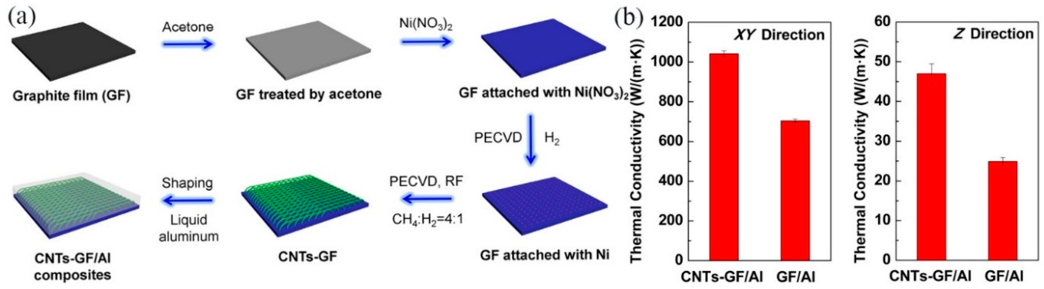
  86. Chang, J.; Zhang, Q.; Lin, Y.; Zhou, C.; Yang, W.; Yan, L.; Wu, G. Carbon Nanotubes Grown on Graphite Films as Effective Interface Enhancement for an Aluminum Matrix Laminated Composite in Thermal Management Applications. ACS Appl. Mater. Interfaces 2018, 10, 38350–38358. [Google Scholar] [CrossRef] [PubMed]
  87. Teng, C.; Su, L.; Chen, J.; Wang, J. Flexible, thermally conductive layered composite films from massively exfoliated boron nitride nanosheets. Compos. Part A Appl. Sci. Manuf. 2019, 124, 105498. [Google Scholar] [CrossRef]
  88. Yuan, S.; Bai, J.; Chua, C.K.; Wei, J.; Zhou, K. Highly enhanced thermal conductivity of thermoplastic nanocomposites with a low mass fraction of MWCNTs by a facilitated latex approach. Compos. Part A Appl. Sci. Manuf. 2016, 90, 699–710. [Google Scholar] [CrossRef]
  89. Sohn, Y.; Han, T.; Han, J.H. Effects of shape and alignment of reinforcing graphite phases on the thermal conductivity and the coefficient of thermal expansion of graphite/copper composites. Carbon 2019, 149, 152–164. [Google Scholar] [CrossRef]
  90. Moradi, S.; Calventus, Y.; Román, F.; Hutchinson, J.M. Achieving High Thermal Conductivity in Epoxy Composites: Effect of Boron Nitride Particle Size and Matrix-Filler Interface. Polymer 2019, 11, 1156. [Google Scholar] [CrossRef] [Green Version]
  91. Yu, W.; France, D.M.; Routbort, J.L.; Choi, S.U.S. Review and Comparison of Nanofluid Thermal Conductivity and Heat Transfer Enhancements. Heat Transf. Eng. 2008, 29, 432–460. [Google Scholar] [CrossRef]
  92. Zhou, W.; Zuo, J.; Ren, W. Thermal conductivity and dielectric properties of Al/PVDF composites. Compos. Part A Appl. Sci. Manuf. 2012, 43, 658–664. [Google Scholar] [CrossRef]
  93. Chaudhry, A.; Mabrouk, A.N.; Abdala, A. Thermally enhanced polyolefin composites: Fundamentals, progress, challenges, and prospects. Sci. Technol. Adv. Mater. 2020, 21, 737–766. [Google Scholar] [CrossRef] [PubMed]
  94. Zhao, L.; Yan, L.; Wei, C.; Li, Q.; Huang, X.; Wang, Z.; Fu, M.; Ren, J. Synergistic Enhanced Thermal Conductivity of Epoxy Composites with Boron Nitride Nanosheets and Microspheres. J. Phys. Chem. C 2020, 124, 12723–12733. [Google Scholar] [CrossRef]
  95. Wang, B.; Yin, X.; Peng, D.; Zhang, Y.; Wuab, W.; Gu, X.; Na, B.; Lv, R.; Liu, H. Highly thermally conductive PVDF-based ternary dielectric composites via engineering hybrid filler networks. Compos. Part B Eng. 2020, 191, 107978. [Google Scholar] [CrossRef]
  96. Wang, X.; Wu, P. Preparation of Highly Thermally Conductive Polymer Composite at Low Filler Content via a Self-Assembly Process between Polystyrene Microspheres and Boron Nitride Nanosheets. ACS Appl. Mater. Interfaces 2017, 9, 19934–19944. [Google Scholar] [CrossRef]
  97. Li, J.; Li, F.; Zhao, X.; Zhang, W.; Li, S.; Lu, Y.; Zhang, L. Jelly-Inspired Construction of the Three-Dimensional Interconnected BN Network for Lightweight, Thermally Conductive, and Electrically Insulating Rubber Composites. ACS Appl. Electron. Mater. 2020, 2, 1661–1669. [Google Scholar] [CrossRef]
  98. Giri, A.; Hopkins, P.E. A Review of Experimental and Computational Advances in Thermal Boundary Conductance and Nanoscale Thermal Transport across Solid Interfaces. Adv. Funct. Mater. 2019, 30. [Google Scholar] [CrossRef]
  99. Song, J.; Zhang, Y. Effect of an interface layer on thermal conductivity of polymer composites studied by the design of double-layered and triple-layered composites. Int. J. Heat Mass Transf. 2019, 141, 1049–1055. [Google Scholar] [CrossRef]
  100. Guo, H.; Liu, J.; Wang, Q.; Liu, M.; Du, C.; Li, B.; Feng, L. High thermal conductive poly(vinylidene fluoride)-based composites with well-dispersed carbon nanotubes/graphene three-dimensional network structure via reduced interfacial thermal resistance. Compos. Sci. Technol. 2019, 181, 181. [Google Scholar] [CrossRef]
  101. Tan, S.-H.; Tang, L.-M.; Chen, K.-Q. Phonon scattering and thermal conductance properties in two coupled graphene nanoribbons modulated with bridge atoms. Phys. Lett. A 2014, 378, 1952–1955. [Google Scholar] [CrossRef]
  102. Zhang, L.; Keblinski, P.; Wang, J.-S.; Li, B. Interfacial thermal transport in atomic junctions. Phys. Rev. B 2011, 83. [Google Scholar] [CrossRef] [Green Version]
  103. Ha, S.M.; Lee, H.L.; Lee, S.-G.; Kim, B.G.; Kim, Y.S.; Won, J.C.; Choi, W.J.; Lee, D.C.; Kim, J.; Yoo, Y. Thermal conductivity of graphite filled liquid crystal polymer composites and theoretical predictions. Compos. Sci. Technol. 2013, 88, 113–119. [Google Scholar] [CrossRef]
  104. Liu, W.; Do, I.-H.; Fukushima, H.; Drzal, L.T. Influence of Processing on Morphology, Electrical Conductivity and Flexural Properties of Exfoliated Graphite Nanoplatelets-Polyamide Nanocomposites. Carbon Lett. 2010, 11, 279–284. [Google Scholar] [CrossRef]
  105. Balandin, A.A.; Ghosh, S.; Bao, W.; Calizo, I.; Teweldebrhan, D.; Miao, F.; Lau, C.N. Superior Thermal Conductivity of Single-Layer Graphene. Nano Lett. 2008, 8, 902–907. [Google Scholar] [CrossRef] [PubMed]
  106. Zhuang, Y.; Cao, X.; Zhang, J.; Ma, Y.; Shang, X.; Lu, J.; Yang, S.; Zheng, K.; Ma, Y. Monomer casting nylon/graphene nanocomposite with both improved thermal conductivity and mechanical performance. Compos. Part A Appl. Sci. Manuf. 2019, 120, 49–55. [Google Scholar] [CrossRef]
  107. Mittal, V.; Chaudhry, A.U. Polyethylene-thermally reduced graphene nanocomposites: Comparison of masterbatch and direct melt mixing approaches on mechanical, thermal, rheological, and morphological properties. Colloid Polym. Sci. 2016, 294, 1659–1670. [Google Scholar] [CrossRef]
  108. Zhang, F.; Fan, K.; Saba, F.; Yu, J. Graphene reinforced-graphitized nanodiamonds matrix composites: Fabrication, microstructure, mechanical properties, thermal and electrical conductivity. Carbon 2020, 169, 416–428. [Google Scholar] [CrossRef]
  109. Liang, C.; Qiu, H.; Han, Y.; Gu, H.; Song, P.; Wang, L.; Kong, J.; Cao, D.; Gu, J. Superior electromagnetic interference shielding 3D graphene nanoplatelets/reduced graphene oxide foam/epoxy nanocomposites with high thermal conductivity. J. Mater. Chem. C 2019, 7, 2725–2733. [Google Scholar] [CrossRef]
  110. Wang, X.; Wu, P. Highly Thermally Conductive Fluorinated Graphene Films with Superior Electrical Insulation and Mechanical Flexibility. ACS Appl. Mater. Interfaces 2019, 11, 21946–21954. [Google Scholar] [CrossRef]
  111. Zhang, Y.; Choi, J.R.; Park, S.-J. Interlayer polymerization in amine-terminated macromolecular chain-grafted expanded graphite for fabricating highly thermal conductive and physically strong thermoset composites for thermal management applications. Compos. Part A Appl. Sci. Manuf. 2018, 109, 498–506. [Google Scholar] [CrossRef]
  112. Guo, Y.; Yang, X.; Ruan, K.; Kong, J.; Dong, M.; Zhang, J.; Gu, J.; Guo, Z. Reduced Graphene Oxide Heterostructured Silver Nanoparticles Significantly Enhanced Thermal Conductivities in Hot-Pressed Electrospun Polyimide Nanocomposites. ACS Appl. Mater. Interfaces 2019, 11, 25465–25473. [Google Scholar] [CrossRef]
  113. Ji, C.; Yan, C.; Wang, Y.; Xiong, S.; Zhou, F.; Li, Y.-Y.; Sun, R.; Wong, C.-P. Thermal conductivity enhancement of CNT/MoS2/graphene−epoxy nanocomposites based on structural synergistic effects and interpenetrating network. Compos. Part B Eng. 2019, 163, 363–370. [Google Scholar] [CrossRef]
  114. Liu, H.; Gu, S.; Cao, H.; Li, X.; Li, Y. A dense packing structure constructed by flake and spherical graphite: Simultaneously enhanced in-plane and through-plane thermal conductivity of polypropylene/graphite composites. Compos. Commun. 2020, 19, 25–29. [Google Scholar] [CrossRef]
  115. Chenab, W.; Wu, K.; Liuab, Q.; Lua, M.; Protected, E. Functionalization of graphite via Diels-Alder reaction to fabricate poly (vinyl alcohol) composite with enhanced thermal conductivity. Polymer 2020, 186, 122075. [Google Scholar] [CrossRef]
  116. Du, C.; Cao, M.; Li, M.; Guo, H.; Liu, R.; Li, B. Homogeneously dispersed urchin-structured Fe3O4 with graphitic carbon spines inside poly(vinylidene fluoride) for efficient thermal conduction. Compos. Sci. Technol. 2020, 192, 108106. [Google Scholar] [CrossRef]
  117. Yang, B.; Pan, Y.; Yu, Y.; Wu, J.; Xia, R.; Wang, S.; Wang, Y.; Su, L.; Miao, J.; Qian, J.; et al. Filler network structure in graphene nanoplatelet (GNP)-filled polymethyl methacrylate (PMMA) composites: From thermorheology to electrically and thermally conductive properties. Polym. Test. 2020, 89, 106575. [Google Scholar] [CrossRef]
  118. Gong, S.; Cheng, X.; Li, Y.; Wang, X.; Wang, Y.; Zhong, H. Effect of nano-SiC on thermal properties of expanded graphite/1-octadecanol composite materials for thermal energy storage. Powder Technol. 2020, 367, 32–39. [Google Scholar] [CrossRef]
  119. Li, C.; Tan, L.-Y.; Zeng, X.-L.; Zhu, D.; Sun, R.; Xu, J.-B.; Wong, C.-P. Polymer composites with high thermal conductivity optimized by polyline-folded graphite paper. Compos. Sci. Technol. 2020, 188, 107970. [Google Scholar] [CrossRef]
  120. Heab, J.; Wangac, H.; Quab, Q.; Suab, Z.; Qinab, T.; Daab, Y.; Tiana, X. Construction of interconnected SiC particles attached rGO structure in epoxy composites to achieve significant thermal conductivity enhancement. Mater. Today Commun. 2020, 25, 101584. [Google Scholar] [CrossRef]
  121. Ma, M.; Xu, L.; Qiao, L.; Chen, S.; Shi, Y.; He, H.; Wang, X. Nanofibrillated Cellulose/MgO@rGO composite films with highly anisotropic thermal conductivity and electrical insulation. Chem. Eng. J. 2020, 392, 123714. [Google Scholar] [CrossRef]
  122. He, X.; Wang, Y. Highly Thermally Conductive Polyimide Composite Films with Excellent Thermal and Electrical Insulating Properties. Ind. Eng. Chem. Res. 2020, 59, 1925–1933. [Google Scholar] [CrossRef]
  123. Wanga, H.-Y.; Binyoua, Y.; Zhab, J.-W.; Dangc, Z.-M. Fabrication of BaTiO3@super short MWCNTs core-shell particles reinforced PVDF composite films with improved dielectric properties and high thermal conductivity. Compos. Sci. Technol. 2020, 108405. [Google Scholar] [CrossRef]
  124. Wang, R.; Xie, C.; Luo, S.; Xu, H.; Gou, B.; Zeng, L. Preparation and properties of MWCNTs-BNNSs/epoxy composites with high thermal conductivity and low dielectric loss. Mater. Today Commun. 2020, 24, 100985. [Google Scholar] [CrossRef]
  125. Wang, X.; Wu, P. Fluorinated Carbon Nanotube/Nanofibrillated Cellulose Composite Film with Enhanced Toughness, Superior Thermal Conductivity, and Electrical Insulation. ACS Appl. Mater. Interfaces 2018, 10, 34311–34321. [Google Scholar] [CrossRef] [PubMed]
  126. Smith, M.K.; Singh, V.; Kalaitzidou, K.; Cola, B.A. High Thermal and Electrical Conductivity of Template Fabricated P3HT/MWCNT Composite Nanofibers. ACS Appl. Mater. Interfaces 2016, 8, 14788–14794. [Google Scholar] [CrossRef]
  127. Guo, H.; Wang, Q.; Liu, J.; Du, C.; Li, B. Improved interfacial properties for largely enhanced thermal conductivity of poly(vinylidene fluoride)-based nanocomposites via functionalized multi-wall carbon nanotubes. Appl. Surf. Sci. 2019, 487, 379–388. [Google Scholar] [CrossRef]
  128. Anis, B.; El Fllah, H.; Ismail, T.; Fathallah, W.M.; Khalil, A.; Hemeda, O.; Badr, Y.A. Preparation, characterization, and thermal conductivity of polyvinyl-formaldehyde/MWCNTs foam: A low cost heat sink substrate. J. Mater. Res. Technol. 2020, 9, 2934–2945. [Google Scholar] [CrossRef]
  129. Goto, T.; Ito, T.; Mayumi, K.; Maeda, R.; Shimizu, Y.; Hatakeyama, K.; Ito, K.; Hakuta, Y.; Terashima, K. Movable cross-linked elastomer with aligned carbon nanotube/nanofiber as high thermally conductive tough flexible composite. Compos. Sci. Technol. 2020, 190, 108009. [Google Scholar] [CrossRef]
  130. Wanga, Z.-G.; Yanga, Y.-L.; Zhenga, Z.-L.; Lana, R.-T.; Daib, K.; Xua, L.; Huanga, H.-D.; Tangc, J.-H.; Xua, J.-Z.; Lia, Z.-M. Achieving excellent thermally conductive and electromagnetic shielding performance by nondestructive functionalization and oriented arrangement of carbon nanotubes in composite films. Compos. Sci. Technol. 2020, 194, 108190. [Google Scholar] [CrossRef]
  131. He, X.; Huang, Y.; Liu, Y.; Zheng, X.; Kormakov, S.; Sun, J.; Zhuang, J.; Gao, X.; Wu, D. Improved thermal conductivity of polydimethylsiloxane/short carbon fiber composites prepared by spatial confining forced network assembly. J. Mater. Sci. 2018, 53, 14299–14310. [Google Scholar] [CrossRef]
  132. Zhang, H.; Zhang, X.; Li, D.; Yang, X.; Wu, D.; Sun, J. Thermal conductivity enhancement via conductive network conversion from “sand-like” to “stone-like” in the polydimethylsiloxane composites. Compos. Commun. 2020, 22, 100509. [Google Scholar] [CrossRef]
  133. Wang, H.; Li, L.; Chen, Y.; Li, M.; Fu, H.; Hou, X.; Wu, X.; Lin, C.-T.; Jiang, N.; Yu, J. Efficient Thermal Transport Highway Construction Within Epoxy Matrix via Hybrid Carbon Fibers and Alumina Particles. ACS Omega 2020, 5, 1170–1177. [Google Scholar] [CrossRef] [PubMed] [Green Version]
  134. Zhao, Y.-H.; Zhang, Y.-F.; Bai, S.; Yuan, X.-W. Carbon fibre/graphene foam/polymer composites with enhanced mechanical and thermal properties. Compos. Part B Eng. 2016, 94, 102–108. [Google Scholar] [CrossRef]
  135. Owais, M.; Zhao, J.; Imani, A.; Wang, G.; Zhang, H.; Zhang, Z. Synergetic effect of hybrid fillers of boron nitride, graphene nanoplatelets, and short carbon fibers for enhanced thermal conductivity and electrical resistivity of epoxy nanocomposites. Compos. Part A Appl. Sci. Manuf. 2019, 117, 11–22. [Google Scholar] [CrossRef]
  136. Wei, J.; Liao, M.; Ma, A.; Chen, Y.; Duan, Z.; Hou, X.; Li, M.; Jiang, N.; Yu, J. Enhanced thermal conductivity of polydimethylsiloxane composites with carbon fiber. Compos. Commun. 2020, 17, 141–146. [Google Scholar] [CrossRef]
  137. Ji, J.; Chiang, S.-W.; Liu, M.; Liang, X.; Li, J.; Gan, L.; He, Y.; Li, B.; Kang, F.; Du, H. Enhanced thermal conductivity of alumina and carbon fibre filled composites by 3-D printing. Thermochim. Acta 2020, 690, 178649. [Google Scholar] [CrossRef]
  138. Ma, J.; Shang, T.; Ren, L.; Yao, Y.; Zhang, T.; Xie, J.; Zhang, B.; Zeng, X.; Sun, R.; Xu, J.-B.; et al. Through-plane assembly of carbon fibers into 3D skeleton achieving enhanced thermal conductivity of a thermal interface material. Chem. Eng. J. 2020, 380, 122550. [Google Scholar] [CrossRef]
  139. Guo, L.; Zhang, Z.; Li, M.; Kang, R.; Chen, Y.; Song, G.; Han, S.-T.; Lin, C.-T.; Jiang, N.; Yu, J. Extremely high thermal conductivity of carbon fiber/epoxy with synergistic effect of MXenes by freeze-drying. Compos. Commun. 2020, 19, 134–141. [Google Scholar] [CrossRef]
  140. Yu, C.; Zhang, Q.; Zhang, J.; Geng, R.; Tian, W.; Fan, X.; Yao, Y. One-Step in Situ Ball Milling Synthesis of Polymer-Functionalized Few-Layered Boron Nitride and Its Application in High Thermally Conductive Cellulose Composites. ACS Appl. Nano Mater. 2018, 1, 4875–4883. [Google Scholar] [CrossRef]
  141. Ma, T.; Zhao, Y.; Ruan, K.; Liu, X.; Zhang, J.; Guo, Y.; Yang, X.; Kong, J.; Gu, J. Highly Thermal Conductivities, Excellent Mechanical Robustness and Flexibility, and Outstanding Thermal Stabilities of Aramid Nanofiber Composite Papers with Nacre-Mimetic Layered Structures. ACS Appl. Mater. Interfaces 2019, 12, 1677–1686. [Google Scholar] [CrossRef]
  142. Huang, T.; Li, Y.; Chen, M.; Wu, L. Bi-directional high thermal conductive epoxy composites with radially aligned boron nitride nanosheets lamellae. Compos. Sci. Technol. 2020, 198, 108322. [Google Scholar] [CrossRef]
  143. Wang, X.; Wu, P. 3D Vertically Aligned BNNS Network with Long-Range Continuous Channels for Achieving a Highly Thermally Conductive Composite. ACS Appl. Mater. Interfaces 2019, 11, 28943–28952. [Google Scholar] [CrossRef] [PubMed]
  144. Li, M.; Wang, M.; Hou, X.; Zhan, Z.; Wang, H.; Fu, H.; Lin, C.-T.; Fu, L.; Jiang, N.; Yu, J. Highly thermal conductive and electrical insulating polymer composites with boron nitride. Compos. Part B Eng. 2020, 184, 107746. [Google Scholar] [CrossRef]
  145. Xiao, G.; Di, J.; Li, H.; Wang, J. Highly thermally conductive, ductile biomimetic boron nitride/aramid nanofiber composite film. Compos. Sci. Technol. 2020, 189, 108021. [Google Scholar] [CrossRef]
  146. Shi, A.; Li, Y.; Liu, W.; Xu, J.-Z.; Yan, D.-X.; Lei, J.; Li, Z.-M. Highly thermally conductive and mechanically robust composite of linear ultrahigh molecular weight polyethylene and boron nitride via constructing nacre-like structure. Compos. Sci. Technol. 2019, 184, 107858. [Google Scholar] [CrossRef]
  147. Jiaa, X.; Lia, Q.; Aoa, C.; Hua, R.; Xiaa, T.; Xuea, Z.; Wanga, Q.; Denga, X.; Zhang, W.; Lu, C. High thermal conductive shape-stabilized phase change materials of polyethylene glycol/boron nitride@chitosan composites for thermal energy storage. Compos. Part A Appl. Sci. Manuf. 2020, 129, 105710. [Google Scholar] [CrossRef]
  148. Li, Q.; Xue, Z.; Zhao, J.; Ao, C.; Jia, X.; Xia, T.; Wang, Q.; Deng, X.; Zhang, W.; Lu, C. Mass production of high thermal conductive boron nitride/nanofibrillated cellulose composite membranes. Chem. Eng. J. 2020, 383, 123101. [Google Scholar] [CrossRef]
  149. Hwang, Y.J.; Kim, J.M.; Kim, L.S.; Jang, J.Y.; Kim, M.; Jeong, S.; Cho, J.Y.; Yi, G.-R.; Choi, Y.S.; Lee, G. Epoxy-based thermally conductive adhesives with effective alumina and boron nitride for superconducting magnet. Compos. Sci. Technol. 2020, 200, 108456. [Google Scholar] [CrossRef]
  150. Akhtar, M.W.; Kim, J.S.; Memon, M.A.; Baloch, M.M. Hybridization of hexagonal boron nitride nanosheets and multilayer graphene: Enhanced thermal properties of epoxy composites. Compos. Sci. Technol. 2020, 195, 108183. [Google Scholar] [CrossRef]
  151. Hu, B.; Guo, H.; Wang, Q.; Zhang, W.; Song, S.; Li, X.; Li, Y.; Li, B. Enhanced thermal conductivity by constructing 3D-networks in poly(vinylidene fluoride) composites via positively charged hexagonal boron nitride and silica coated carbon nanotubes. Compos. Part A Appl. Sci. Manuf. 2020, 137, 106038. [Google Scholar] [CrossRef]
  152. Liu, Z.; Li, J.; Liu, X. Novel Functionalized BN Nanosheets/Epoxy Composites with Advanced Thermal Conductivity and Mechanical Properties. ACS Appl. Mater. Interfaces 2020, 12, 6503–6515. [Google Scholar] [CrossRef]
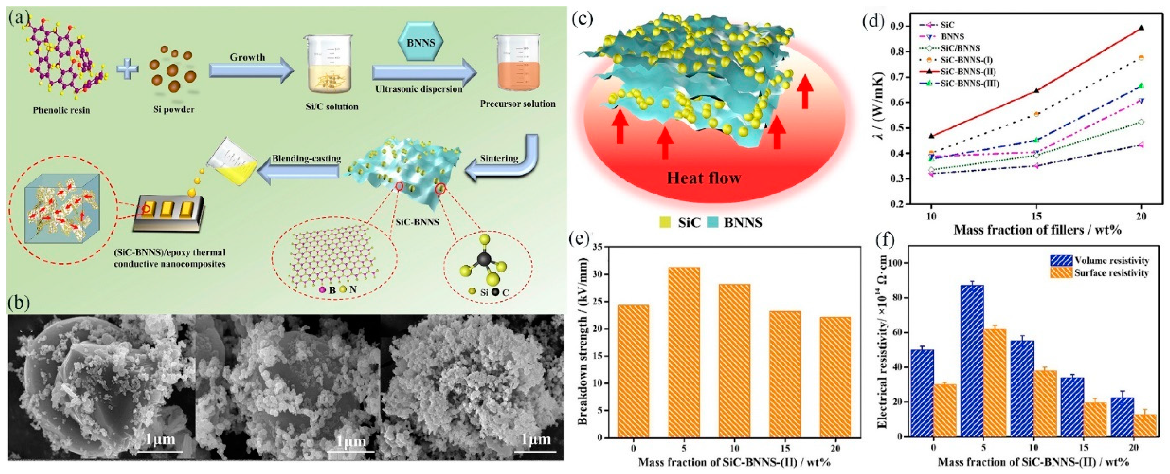
  153. Han, Y.; Shi, X.; Yang, X.; Guo, Y.; Zhang, J.; Kong, J.; Gu, J. Enhanced thermal conductivities of epoxy nanocomposites via incorporating in-situ fabricated hetero-structured SiC-BNNS fillers. Compos. Sci. Technol. 2020, 187, 187. [Google Scholar] [CrossRef]
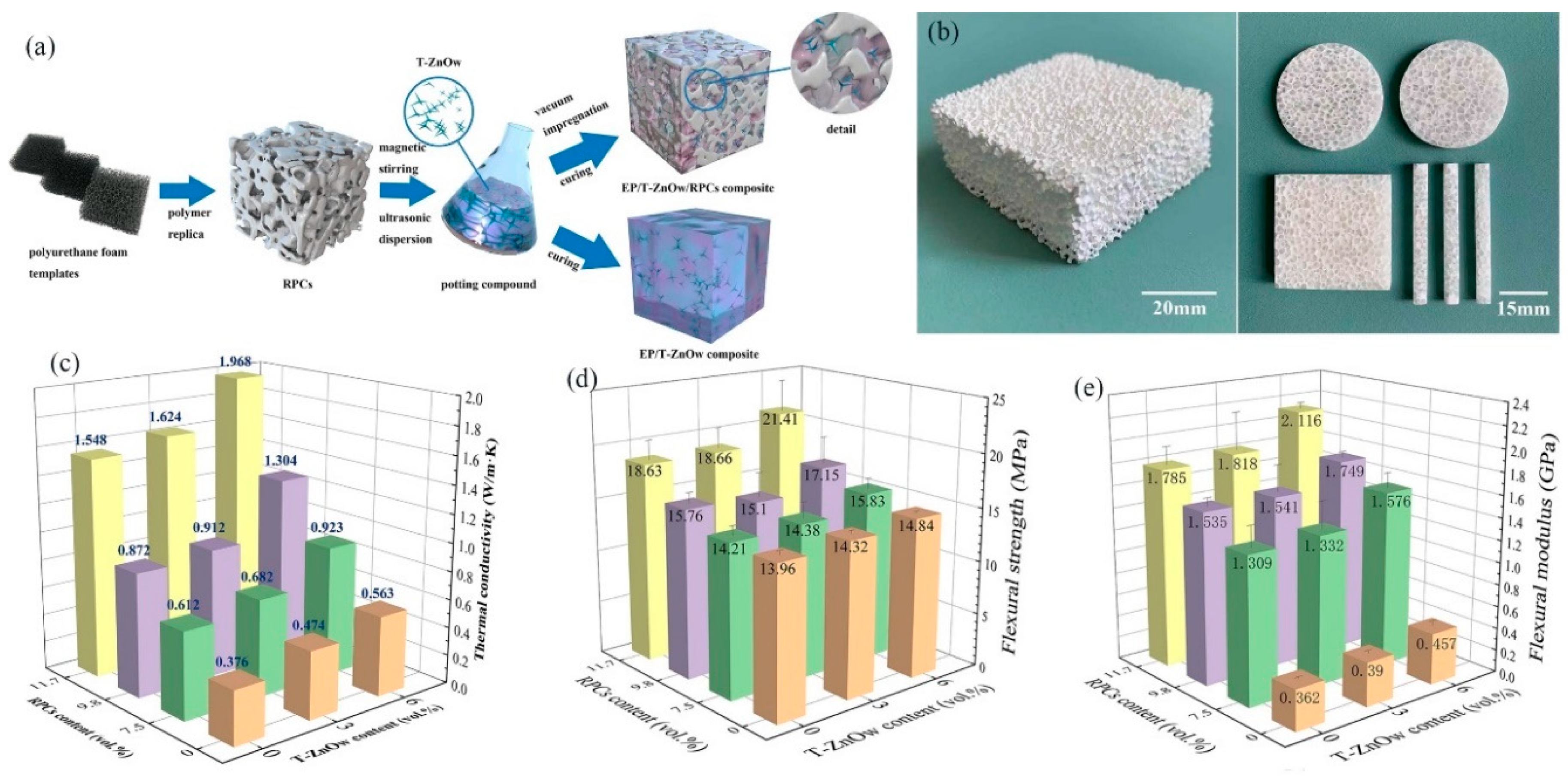
  154. Wu, B.; Li, Y.; Fu, R.; Agathopoulos, S.; Su, X.; Liu, H. Low thermal expansion coefficient and high thermal conductivity epoxy/Al2O3/T-ZnOw composites with dual-scale interpenetrating network structure. Compos. Part A Appl. Sci. Manuf. 2020, 137, 105993. [Google Scholar] [CrossRef]
  155. Li, C.; Liu, B.; Gao, Z.; Wang, H.; Liu, M.; Wang, S.; Xiong, C.-X. Electrically insulating ZnOs/ZnOw/silicone rubber nanocomposites with enhanced thermal conductivity and mechanical properties. J. Appl. Polym. Sci. 2018, 135. [Google Scholar] [CrossRef]
  156. Yan, R.; Su, F.; Zhang, L.; Li, C. Highly enhanced thermal conductivity of epoxy composites by constructing dense thermal conductive network with combination of alumina and carbon nanotubes. Compos. Part A Appl. Sci. Manuf. 2019, 125, 105496. [Google Scholar] [CrossRef]
  157. Xiao, C.; Chen, L.; Tang, Y.; Zhang, X.; Zheng, K.; Tian, X. Three dimensional porous alumina network for polymer composites with enhanced thermal conductivity. Compos. Part A Appl. Sci. Manuf. 2019, 124, 105511. [Google Scholar] [CrossRef]
  158. Yuan, Y.; Li, Z.; Cao, L.; Tang, B.; Zhang, S. Modification of Si3N4 ceramic powders and fabrication of Si3N4/PTFE composite substrate with high thermal conductivity. Ceram. Int. 2019, 45, 16569–16576. [Google Scholar] [CrossRef]
  159. Guana, C.; Qinab, Y.; Wangb, B.; Lib, L.; Wangb, M.; Linbc, C.-T.; Hed, X.; Nishimurae, K.; Yu, J.; Yibc, J.; et al. Highly thermally conductive polymer composites with barnacle-like nano-crystalline Diamond@Silicon carbide hybrid architecture. Compos. Part B Eng. 2020, 198, 108167. [Google Scholar] [CrossRef]
  160. Vu, M.C.; Choi, W.-K.; Lee, S.G.; Park, P.J.; Kim, D.H.; Islam, A.; Kim, S.-R. High Thermal Conductivity Enhancement of Polymer Composites with Vertically Aligned Silicon Carbide Sheet Scaffolds. ACS Appl. Mater. Interfaces 2020, 12, 23388–23398. [Google Scholar] [CrossRef]
  161. Vu, M.C.; Thieu, N.A.T.; Choi, W.K.; Islam, A.; Kim, S.-R. Ultralight covalently interconnected silicon carbide aerofoam for high performance thermally conductive epoxy composites. Compos. Part A Appl. Sci. Manuf. 2020, 138, 106028. [Google Scholar] [CrossRef]
  162. Wei, Z.; Xie, W.; Ge, B.; Zhang, Z.; Yang, W.; Xia, H.; Wang, B.; Jin, H.; Gao, N.; Shi, Z. Enhanced thermal conductivity of epoxy composites by constructing aluminum nitride honeycomb reinforcements. Compos. Sci. Technol. 2020, 199, 108304. [Google Scholar] [CrossRef]
  163. Liu, M.; Chiang, S.-W.; Chu, X.; Li, J.; Gan, L.; He, Y.; Li, B.; Kang, F.; Du, H. Polymer composites with enhanced thermal conductivity via oriented boron nitride and alumina hybrid fillers assisted by 3-D printing. Ceram. Int. 2020, 46, 20810–20818. [Google Scholar] [CrossRef]
  164. Zhang, K.; Tao, P.; Zhang, Y.; Liao, X.; Nie, S. Highly thermal conductivity of CNF/AlN hybrid films for thermal management of flexible energy storage devices. Carbohydr. Polym. 2019, 213, 228–235. [Google Scholar] [CrossRef] [PubMed]
  165. Ji, C.; Wang, Y.; Ye, Z.; Tan, L.; Mao, D.; Zhao, W.; Zeng, X.; Yan, C.; Sun, R.; Kang, D.J.; et al. Ice-Templated MXene/Ag–Epoxy Nanocomposites as High-Performance Thermal Management Materials. ACS Appl. Mater. Interfaces 2020, 12, 24298–24307. [Google Scholar] [CrossRef] [PubMed]
  166. Yan, C.; Yu, T.; Ji, C.; Kang, D.J.; Wang, N.; Sun, R.; Wong, C.-P. Tailoring Highly Thermal Conductive Properties of Te/MoS2 /Ag Heterostructure Nanocomposites Using a Bottom-Up Approach. Adv. Electron. Mater. 2019, 5. [Google Scholar] [CrossRef] [Green Version]
  167. Ha, T.; Kim, D.-G.; Ka, J.-W.; Kim, Y.S.; Koh, W.-G.; Lim, H.S.; Yoo, Y. Simultaneous effects of silver-decorated graphite nanoplatelets and anisotropic alignments on improving thermal conductivity of stretchable poly(vinyl alcohol) composite films. Compos. Part A Appl. Sci. Manuf. 2020, 138, 106045. [Google Scholar] [CrossRef]
  168. Wang, Y.; Wu, W.; Drummer, D.; Liu, C.; Shen, W.; Tomiak, F.; Schneider, K.; Liu, X.; Chen, Q. Highly thermally conductive polybenzoxazine composites based on boron nitride flakes deposited with copper particles. Mater. Des. 2020, 191, 108698. [Google Scholar] [CrossRef]
  169. Vu, M.C.; Bach, Q.-V.; Nguyen, D.D.; Tran, T.S.; Goodarzi, M. 3D interconnected structure of poly(methyl methacrylate) microbeads coated with copper nanoparticles for highly thermal conductive epoxy composites. Compos. Part B Eng. 2019, 175, 107105. [Google Scholar] [CrossRef]
  170. Dai, S.; Li, J.; Lu, N. Research progress of diamond/copper composites with high thermal conductivity. Diam. Relat. Mater. 2020, 108, 107993. [Google Scholar] [CrossRef]
  171. Progelhof, R.C.; Throne, J.L.; Ruetsch, R.R. Methods for predicting the thermal conductivity of composite systems: A review. Polym. Eng. Sci. 1976, 16, 615–625. [Google Scholar] [CrossRef]
  172. Agari, Y.; Uno, T. Estimation on thermal conductivities of filled polymers. J. Appl. Polym. Sci. 1986, 32, 5705–5712. [Google Scholar] [CrossRef]
  173. Maxwell, J.C. A Treatise on Electricity and Magnetism; Clarendon Press: Oxford, UK, 1873; Volume 1. [Google Scholar]
  174. Stoner, R.J.; Maris, H.J.; Anthony, T.R.; Banholzer, W.F. Measurements of the Kapitza conductance between diamond and several metals. Phys. Rev. Lett. 1992, 68, 1563–1566. [Google Scholar] [CrossRef] [PubMed]
  175. Hasselman, D.P.H.; Donaldson, K.Y.; Liu, J.; Gauckler, L.J.; Ownby, P.D. Thermal Conductivity of a Particulate-Diamond-Reinforced Cordierite Matrix Composite. J. Am. Ceram. Soc. 1994, 77, 1757–1760. [Google Scholar] [CrossRef]
  176. Hasselman, D.P.H.; Donaldson, K.Y.; Geiger, A.L. Effect of Reinforcement Particle Size on the Thermal Conductivity of a Particulate-Silicon Carbide-Reinforced Aluminum Matrix Composite. J. Am. Ceram. Soc. 1992, 75, 3137–3140. [Google Scholar] [CrossRef]
  177. Bruggeman, D. Effective medium model for the optical properties of composite materials. Ann. Phys. 1935, 24, 636. [Google Scholar] [CrossRef]
  178. Hamilton, R.L.; Crosser, O.K. Thermal Conductivity of Heterogeneous Two-Component Systems. Ind. Eng. Chem. Fundam. 1962, 1, 187–191. [Google Scholar] [CrossRef]
  179. Kochetov, R.; Andritsch, T.; Lafont, U.; Morshuis, P.H.F.; Picken, S.; Smit, J.J. Thermal behaviour of epoxy resin filled with high thermal conductivity nanopowders. In Proceedings of the 2009 IEEE Electrical Insulation Conference, Montreal, QC, Canada, 31 May–3 June 2009; pp. 524–528. [Google Scholar]
  180. Agari, Y.; Tanaka, M.; Nagai, S.; Uno, T. Thermal conductivity of a polymer composite filled with mixtures of particles. J. Appl. Polym. Sci. 1987, 34, 1429–1437. [Google Scholar] [CrossRef]
  181. Krasnobokii, Y.N.; Dushchenko, V.P.; Duginov, V.E.; Baranovskii, V.M.; Luchitskii, P.G. Dielectric investigation of the effect of fillers and plasticizers on molecular mobility in an epoxide resin. Russ. Phys. J. 1972, 15, 599–601. [Google Scholar] [CrossRef]
  182. Agari, Y.; Ueda, A.; Nagai, S. Thermal conductivity of a polyethylene filled with disoriented short-cut carbon fibers. J. Appl. Polym. Sci. 1991, 43, 1117–1124. [Google Scholar] [CrossRef]
  183. Shimizu, T.; Matsuura, K.; Furue, H.; Matsuzak, K. Thermal conductivity of high porosity alumina refractory bricks made by a slurry gelation and foaming method. J. Eur. Ceram. Soc. 2013, 33, 3429–3435. [Google Scholar] [CrossRef] [Green Version]
  184. Drozdov, A.; Christiansen, J.D.C. Thermal conductivity of highly filled polymer nanocomposites. Compos. Sci. Technol. 2019, 182, 107717. [Google Scholar] [CrossRef]
  185. Xu, W.-X.; Liang, X.-G. Molecular Dynamics Simulation of Effects of Stretching and Compressing on Thermal Conductivity of Aligned Silicon Oxygen Chains. Chin. Phys. Lett. 2020, 37, 046601. [Google Scholar] [CrossRef]
  186. Chou, F.-C.; Lukes, J.R.; Liang, X.-G.; Takahashi, K.; Tien, C.-L. Molecular dynamics in microscale thermophysical engineering. Annu. Rev. Heat Transf. 1999, 10, 141–176. [Google Scholar] [CrossRef]
  187. Allen, M.P.; Tildesley, D.J. Computer Simulation of Liquids; Oxford University Press: Oxford, UK, 1988. [Google Scholar]
  188. Schelling, P.K.; Phillpot, S.R.; Keblinski, P. Comparison of atomic-level simulation methods for computing thermal conductivity. Phys. Rev. B 2002, 65, 144306. [Google Scholar] [CrossRef] [Green Version]
  189. Feng, D.; Feng, Y.; Qiu, L.; Li, P.; Zang, Y.; Zou, H.; Yu, Z.; Zhang, X. Review on nanoporous composite phase change materials: Fabrication, characterization, enhancement and molecular simulation. Renew. Sustain. Energy Rev. 2019, 109, 578–605. [Google Scholar] [CrossRef]
  190. Müller-Plathe, F. A simple nonequilibrium molecular dynamics method for calculating the thermal conductivity. J. Chem. Phys. 1997, 106, 6082–6085. [Google Scholar] [CrossRef]
  191. Yao, Y.; Ye, Z.; Huang, F.; Zeng, X.; Zhang, T.; Shang, T.; Han, M.; Zhang, W.; Ren, L.; Sun, R.; et al. Achieving Significant Thermal Conductivity Enhancement via an Ice-Templated and Sintered BN-SiC Skeleton. ACS Appl. Mater. Interfaces 2019, 12, 2892–2902. [Google Scholar] [CrossRef]
  192. Plimpton, S. Fast Parallel Algorithms for Short-Range Molecular Dynamics. J. Comput. Phys. 1995, 117, 1–19. [Google Scholar] [CrossRef] [Green Version]
  193. Dai, W.; Ma, T.; Yan, Q.; Gao, J.; Tan, X.; Lv, L.; Hou, H.; Wei, Q.; Yu, J.; Wu, J.; et al. Metal-Level Thermally Conductive yet Soft Graphene Thermal Interface Materials. ACS Nano 2019, 13, 11561–11571. [Google Scholar] [CrossRef]
  194. Xu, W.; Wu, Y.; Zhu, Y.; Liang, X.-G. Molecular dynamics simulation of thermal conductivity of silicone rubber. Chin. Phys. B 2020, 29, 046601. [Google Scholar] [CrossRef]
  195. Ritz, W. Über eine neue Methode zur Lösung gewisser Variationsprobleme der mathematischen Physik. J. Reine Angew. Math. 1909, 1909, 1–61. [Google Scholar] [CrossRef]
  196. Clough, R.W. The Finite Element Method in Plane Stress Analysis; American Society of Civil Engineers: Reston, VA, USA, 1960. [Google Scholar]
  197. Taylor, R.L.; Taylor, R.L.; Zienkiewicz, O.C. The Finite Element Method for Solid and Structural Mechanics; Elsevier: Amsterdam, The Netherlands, 2013. [Google Scholar]
  198. Courant, R. Variational methods for the solution of problems of equilibrium and vibrations. Lect. Notes Pure Appl. Math. 1994, 49, 1–23. [Google Scholar]
  199. Feng, C.-P.; Chen, L.-B.; Tian, G.-L.; Wan, S.-S.; Bai, L.; Bao, R.-Y.; Liu, Z.-Y.; Yang, M.; Yang, W. Multifunctional Thermal Management Materials with Excellent Heat Dissipation and Generation Capability for Future Electronics. ACS Appl. Mater. Interfaces 2019, 11, 18739–18745. [Google Scholar] [CrossRef]
  200. Chen, J.; Wei, H.; Bao, H.; Jiang, P.; Huang, X. Millefeuille-Inspired Thermally Conductive Polymer Nanocomposites with Overlapping BN Nanosheets for Thermal Management Applications. ACS Appl. Mater. Interfaces 2019, 11, 31402–31410. [Google Scholar] [CrossRef] [PubMed]
  201. Dai, W.; Lv, L.; Lu, J.; Hou, H.; Yan, Q.; Alam, F.E.; Li, Y.; Zeng, X.; Yu, J.; Wei, Q.; et al. A Paper-Like Inorganic Thermal Interface Material Composed of Hierarchically Structured Graphene/Silicon Carbide Nanorods. ACS Nano 2019, 13, 1547–1554. [Google Scholar] [CrossRef] [PubMed]
  202. Zhu, Z.; Wang, P.; Lv, P.; Xu, T.; Zheng, J.; Ma, C.; Yu, K.; Feng, W.; Wei, W.; Chen, L. Densely packed polymer/boron nitride composite for superior anisotropic thermal conductivity. Polym. Compos. 2017, 39, E1653–E1658. [Google Scholar] [CrossRef]
  203. An, F.; Li, X.; Min, P.; Liu, P.; Jiang, Z.-G.; Yu, Z.-Z. Vertically Aligned High-Quality Graphene Foams for Anisotropically Conductive Polymer Composites with Ultrahigh Through-Plane Thermal Conductivities. ACS Appl. Mater. Interfaces 2018, 10, 17383–17392. [Google Scholar] [CrossRef] [PubMed]
  204. Yang, J.; Qi, G.-Q.; Tang, L.-S.; Bao, R.-Y.; Bai, L.; Liu, Z.-Y.; Yang, W.; Xie, B.-H.; Yang, M.-B. Novel photodriven composite phase change materials with bioinspired modification of BN for solar-thermal energy conversion and storage. J. Mater. Chem. A 2016, 4, 9625–9634. [Google Scholar] [CrossRef]
  205. Kusunose, T.; Yagi, T.; Firoz, S.H.; Sekino, T. Fabrication of epoxy/silicon nitride nanowire composites and evaluation of their thermal conductivity. J. Mater. Chem. A 2013, 1, 3440–3445. [Google Scholar] [CrossRef]
  206. Fu, L.; Wang, T.; Yu, J.; Dai, W.; Sun, H.; Liu, Z.; Sun, R.; Jiang, N.; Yu, A.-M.; Lin, C.-T. An ultrathin high-performance heat spreader fabricated with hydroxylated boron nitride nanosheets. 2D Mater. 2017, 4, 025047. [Google Scholar] [CrossRef]
  207. Xin, G.; Sun, H.; Hu, T.; Fard, H.R.; Sun, X.; Koratkar, N.; Borca-Tasciuc, T.; Lian, J. Large-Area Freestanding Graphene Paper for Superior Thermal Management. Adv. Mater. 2014, 26, 4521–4526. [Google Scholar] [CrossRef]
  208. Wang, J.; Wu, Y.; Xue, Y.; Liu, D.; Wang, X.-B.; Hu, X.; Bando, Y.; Lei, W. Super-compatible functional boron nitride nanosheets/polymer films with excellent mechanical properties and ultra-high thermal conductivity for thermal management. J. Mater. Chem. C 2018, 6, 1363–1369. [Google Scholar] [CrossRef]
  209. Zhou, T.; Wei, H.; Tan, H.; Wang, X.; Zeng, H.; Liu, X.; Nagao, S.; Koga, H.; Nogi, M.; Sugahara, T.; et al. Strongly anisotropic thermal conductivity and adequate breathability of bilayered films for heat management of on-skin electronics. 2D Mater. 2018, 5, 035013. [Google Scholar] [CrossRef]
  210. Uetani, K.; Ata, S.; Tomonoh, S.; Yamada, T.; Yumura, M.; Hata, K. Elastomeric Thermal Interface Materials with High Through-Plane Thermal Conductivity from Carbon Fiber Fillers Vertically Aligned by Electrostatic Flocking. Adv. Mater. 2014, 26, 5857–5862. [Google Scholar] [CrossRef] [PubMed]
  211. An, F.; Li, X.; Min, P.; Li, H.; Dai, Z.; Yu, Z.-Z. Highly anisotropic graphene/boron nitride hybrid aerogels with long-range ordered architecture and moderate density for highly thermally conductive composites. Carbon 2018, 126, 119–127. [Google Scholar] [CrossRef]
  212. Qin, M.; Xu, Y.; Cao, R.; Feng, W.; Chen, L. Efficiently Controlling the 3D Thermal Conductivity of a Polymer Nanocomposite via a Hyperelastic Double-Continuous Network of Graphene and Sponge. Adv. Funct. Mater. 2018, 28, 28. [Google Scholar] [CrossRef]
  213. Tian, Z.; Sun, J.; Wang, S.; Zeng, X.; Zhou, S.; Bai, S.; Zhao, N.; Wong, C.-P. A thermal interface material based on foam-templated three-dimensional hierarchical porous boron nitride. J. Mater. Chem. A 2018, 6, 17540–17547. [Google Scholar] [CrossRef]
  214. Zhang, X.; Zheng, J.; Fang, H.; Zhang, Y.; Bai, S.; He, G. Al2O3/graphene reinforced bio-inspired interlocking polyurethane composites with superior mechanical and thermal properties for solid propulsion fuel. Compos. Sci. Technol. 2018, 167, 42–52. [Google Scholar] [CrossRef]
  215. Chen, J.; Huang, X.; Sun, B.; Jiang, P. Highly Thermally Conductive Yet Electrically Insulating Polymer/Boron Nitride Nanosheets Nanocomposite Films for Improved Thermal Management Capability. ACS Nano 2019, 13, 337–345. [Google Scholar] [CrossRef]
  216. Tian, X.; Pan, T.; Deng, B.; Zhang, H.; Li, Y.; Li, Q.; Li, Y. Synthesis of Sandwich-Like Nanostructure Fillers and Their Use in Different Types of Thermal Composites. ACS Appl. Mater. Interfaces 2019, 11, 40694–40703. [Google Scholar] [CrossRef]
Figure 1. Thermal networks of (a) 0-D, (b) 1-D, (c) 2-D, and (d) 3-D fillers (reproduced with permission from [94,95,96,97]).
Jcs 04 00180 g001
Figure 2. Dispersion of (a) 0-D, (b) 1-D, and (c) 2-D fillers in matrices (reproduced with permission from [28,79,96]).
Jcs 04 00180 g002
Figure 3. (a) Schematic illustration of the preparation process for graphite composites bulks. (b) Thermal diffusivity and (c) electrical conductivity of sintered samples with different graphene (Gr) contents (reproduced with permission from [108]).
Jcs 04 00180 g003
Figure 4. (a) Schematic diagram for the fabrication of 3D graphene nanoplatelets (GNPs)/reduced graphene oxide (rGO)/EP and GNPs/EP nanocomposites. (b,c) Effect of the GNP content on the thermal and electrical conductivity. (d) Electromagnetic interference shielding (EMI SE) of the rGO/EP and 3D GNPs/rGO/EP nanocomposites at the X-band. (e) Schematic of the electromagnetic wave transfer across the 3D GNPs/rGO/EP nanocomposites (reproduced with permission from [109]).
Jcs 04 00180 g004
Figure 5. (a) Schematic diagram of the exfoliation of fluorinated (F)-graphite and the preparation process of F-graphene composites films. (b) The thermal conductivity and (c) volume resistivity of F-graphene composites films. (d) The heat-conduction mechanism of F-graphene composites films (reproduced with permission from [110]).
Jcs 04 00180 g005
Figure 6. (a) Schematic diagram of the preparation of barium titanate@super short multiwalled carbon nanotube (BT@SSCNT) core–shell nanoparticles. (b) Dielectric properties and (c) λ of the BT@SSCNT/PVDF composites films (reproduced with permission from [123]).
Jcs 04 00180 g006
Figure 7. (a) Preparation process and principle of high-thermal-conductivity epoxy resin. (b) Alternating-current (AC) conductivity of the epoxy nanocomposites. (c) λ of pure epoxy and its nanocomposites with different nanofillers (reproduced with permission from [124]).
Jcs 04 00180 g007
Figure 8. (a) Schematic illustration of the preparation of the nano-fibrillated cellulose/fluorinated carbon nanotubes (NFC/FCNT) composites films. (b) The cross-sectional morphology of NFC/(35 wt.%) FCNT. (c) λ of NFC/FCNT. (d) Volume electrical resistivity of NFC/FCNT and NFC/CNT composites films (reproduced with permission from [125]).
Jcs 04 00180 g008
Figure 9. (a) Scheme of technological pathway of spatial confining forced network assembly (SCFNA) method and conventional compounding. (b) λ of PDMS/short-carbon-fiber (SCF) composites with different thicknesses. (c) The thermal and (d) electrical conductivity of PDMS/SCF composites [131].
Jcs 04 00180 g009
Figure 10. (a) Schematic diagram of the SCFNA method for the preparation of the PDMS/SCF/glass bubbles (GB) composites. (b) λ and (c) elongation-at-break of the PDMS/SCF/GB composites at different thicknesses of sample. (d) The thermally conductive network conversion from “sand-like” to “stone-like” [132].
Jcs 04 00180 g010
Figure 11. (a) Schematic diagram of the preparation of epoxy/carbon fiber (CF)/Al2O3 composites. (b) λ and (c) thermal-conductivity enhancement (TCE) of the pure epoxy, epoxy/CF, and epoxy/CF/Al2O3 composites (reproduced with permission from [133]).
Jcs 04 00180 g011
Figure 12. (a) Schematic diagram for the fabrication of the boron nitride (BN)-PVDF scaffolds and epoxy/BN-PVDF composites. (b) The constructed BN pathway held together by PVDF adhesive. (c) λ of epoxy/BN-PVDF composites (reproduced with permission from [27]).
Jcs 04 00180 g012
Figure 13. (a) Schematic illustration of the preparation of boron nitride nanosheet (BNNS)@PDA/aramid nanofiber (ANF) composites papers. (b) Photographs of BNNS@PDA/ANF composites papers. (c) Tensile stress–strain curves of BNNS/ANF and BNNS@PDA/ANF composites papers. (d) Cross-sectional morphologies of 50 wt.% BNNS@PDA/ANF composites papers and in-plane thermal conductivity coefficient of composites papers (reproduced with permission from [141]).
Jcs 04 00180 g013
Figure 14. (a) Schematic illustration, (b) λ, and (c) electrical properties of boron nitride microsphere (BNMS)/BNNS/epoxy composites. (d) Thermal-conduction pathways in the BNNSs/epoxy, BNMSs/epoxy, and BNNSs/BNMSs/epoxy composites (reproduced with permission from [98]).
Jcs 04 00180 g014
Figure 15. (a) Schematic illustration of the radially aligned BNNS/epoxy. (b) Schematic diagram of the thermal conductivity in the through-plane and in-plane directions. (c) Thermal conductivity of the BNNS/epoxy composites. (d) Change in thermal conductivity of BNNS/epoxy composites with temperature (reproduced with permission from [142]).
Jcs 04 00180 g015
Figure 16. (a) Schematic diagram for the preparation process of Al2O3 nanospheres by thermal plasma and (b) Al2O3/SR composites. (c) λ of Al2O3/SR composites and heat flow models. (d) Volume resistivity of the Al2O3/SR composites (reproduced with permission from [79]).
Jcs 04 00180 g016
Figure 17. (a) Schematic diagram for the fabrication of (SiC-BNNS)/epoxy thermally conductive nano-composites. (b) SEM images of (SiC-BNNS, 2/1)-(I), (SiC-BNNS, 1/1)-(II), and (SiC-BNNS, 1/2)-(III). (c) Thermally conductive mechanism for hetero-structured SiC-BNNS fillers. (d) λ, (e) breakdown strength, and (f) electrical resistivity of the SiC-BNNS-(II)/epoxy thermally conductive nanocomposites (reproduced with permission from [153]).
Jcs 04 00180 g017
Figure 18. (a) Schematic diagram for the fabrication of EP/reticulated porous alumina ceramics (RPCs)/T-ZnOw composites. (b) Typical images of the reticulated porous ceramics (left) and processed samples of EP/RPC/T-ZnOw composites (right). (c) λ, (d) flexural strength, and (e) flexural modulus of EP/RPCs/T-ZnOw composites (reproduced with permission from [154]).
Jcs 04 00180 g018
Figure 19. (a) Schematic of fabrication process of the Cu-Carbon felt (CFelt)/epoxy composites. (b) Schematic illustration of the heat conduction in the CFelt/epoxy and Cu-CFelt/epoxy composites. (c) λ of Cu-CFelt/epoxy (reproduced with permission from [58]).
Jcs 04 00180 g019
Figure 20. (a) Detailed flowchart of preparing the MXene/Ag-epoxy nanocomposites films. (b) 3-D networks and heat transfer and (c) λ of MXene/Ag-epoxy nanocomposites films (reproduced with permission from [165]).
Jcs 04 00180 g020
Figure 21. (a) Schematic of the fabrication process of the CNTs–graphite film (GF)/Al laminated composites block. (b) λ of CNTs–GF/Al and GF/Al composites in the xy and z directions (reproduced with permission from [86]).
Jcs 04 00180 g021
Figure 22. Parallel and series models.
Jcs 04 00180 g022
Figure 23. Molecular dynamics (MD) simulations of the interfacial thermal resistance at BN-SiC junction. (a) Schematic of sintered h-BN/SiC junction. (b) Energy injecting into the heat sink varies with time. (c) Temperature distribution along the x direction (reproduced with permission from [191]).
Jcs 04 00180 g023
Figure 24. (a) Schematic of simulation model. (b) Simulation model with MXene sheets and Ag NPs. (c) Temperature distribution of simulation model with MXene/Ag. Schematic of multilayered (d) Mxene and (e) MXene-Ag. (f) Energy injected into (removing from) the heat sink (source) varies with time (reproduced with permission from [165]).
Jcs 04 00180 g024
Figure 25. (a) Vertical graphene, and L-shaped (b) single-layer, (c) bilayer, and (d) tri-layer graphene, based on nonequilibrium molecular dynamics (NEMD) simulations of the effective contact thermal conductance (reproduced with permission from [193]).
Jcs 04 00180 g025
Figure 26. (a) The geometry and (b) the mesh used in the simulation. (c,f) Modeling and calculation of the temperature in case 1 and case 2, respectively. (d) Average temperature change of the chip with time and (e) the heat transfer rate through the thermal management material (TMM) surface with time when the chip is the heat source. (g,h) The change in the average temperature of the chip with time when the TMM is the heat source and different heat sources of TMMs (reproduced with permission from [199].
Jcs 04 00180 g026
Figure 27. (a) Thermal-conduction pathways in the composites. (b) The simulation result of surface temperature–time profile of epoxy filled with BNMSs and BNNSs/BNMSs. (c,d) BNMSs/epoxy and (f,g) BNNSs/BNMSs/epoxy composites simulation model and temperatures profile for the longitudinal sections, respectively. (e) The BNMSs/epoxy and (h) BNNSs/BNMSs/epoxy composites temperatures at the same cross-sectional position (reproduced with permission from [94]).
Jcs 04 00180 g027
Figure 28. (a) Calculated interfacial thermal resistance (R) of three different nanocomposites. (b) Boundary conditions of the FE simulation. (c) Simulated temperature and heat flux distribution of nanocomposites based on a heat source. (d) Simulated heat flux distribution and thermal conductivity of nanocomposites based on a heat source (reproduced with permission from [200]).
Jcs 04 00180 g028
Figure 29. (a) Icepak system model of the graphene hybrid paper (GHP). (b) Temperature distribution of the simulated system with Bergquist 5000S35 or the GHP as thermal interface materials (TIMs). (c) The heat dissipation based on simulated profiles. (d) Schematic configuration of GHP performance evaluation system. (e,f) Temperature evolution of ceramic heater as a function of heating time at the heater power of 30 W and various applied powers after heating for 200 s (reproduced with permission from [201]).
Jcs 04 00180 g029
Figure 30. (a) Calculated total thermal resistance Rtotal. (b) Comparison of heat dissipation capability based on ANSYS Icepak system model (reproduced with permission from [193]).
Jcs 04 00180 g030
Figure 31. (a) Schematic diagram of a metal–oxide–semiconductor field-effect transistor (MOSFET) integrated with TIMs. (b) The surface temperature variations of MOSFETs versus time (reproduced with permission from [215]). (c) Illustrating heat dissipation measured along the grease filled with BNNS/CNT11%. (d) The comparison for heat dissipation effect between the nanocomposites film and commercial TC grease (reproduced with permission from [216]).
Jcs 04 00180 g031
Figure 32. (a) Diagrams of CPU-GPU integrative fan, thermal pads above CPU and GPU, respectively. (b) The measured CPU encapsulation temperature with different materials (reproduced with permission from [206]). (c) Two films were used as TIMs, respectively. (d) Variation in temperature as a function of time (reproduced with permission from [165]). (e) Two materials were used as TIMs. (f) CPU core temperature evolution as a function of running time and IR images of the 5000S35 and GHP used as TIMs (reproduced with permission from [201]).
Jcs 04 00180 g032
Table 1. λ of commonly used polymer matrices and fillers at room temperature.
Polymer Matricesλ (W/m·K)RefThermally Conductive Fillersλ (W/m·K)Ref
Epoxy (EP)0.22[56,57,58]Graphite1500[59]
Polydimethylsiloxane (PDMS)0.27[10]Graphene~5300[60,61,62]
Ethylene-vinyl acetate copolymer (EVA)0.3[3]Graphene oxide (GO)1000[63]
Polypropylene (PP)0.21[64]CNTs~3500[65,66,67]
Polymethyl methacrylate (PMMA)0.22[41,67,68]Short carbon fibers (SCFs)550[10]
Silicone Rubber (SR)0.21[69,70,71]h-BN600[72]
Polystyrene (PS)0.19[73]BNNS1600–2000[74,75]
Poly (ether-ether-ketone) (PEEK)0.25[76,77]Al2O336[78,79]
Polyvinyl alcohol (PVA)0.22[80]Ag430[81,82]
Polyamide-imide (PAI)0.21[83]Cu350–400[58,84]
Polyimide (PI)0.27[85]Al234[86]
Polyvinylidene fluoride (PVDF)0.2[87]---
Polyamide (PA)0.20[88]---
Polylactic acid (PLA)0.278[13]---
Table 2. λ of graphite and its derivatives/polymer composites.
MatricesFiller Composition and Loadingλ (W/m·K)Years (Ref)
EP10 wt.% expanded graphite (EG)3.82018 [111]
PI3 wt.% Ag + 12 wt.% rGO2.122019 [112]
EP20 wt.% CNT/MoS2/Graphene4.602019 [113]
PAI4.25 wt.% CF/rGO0.532019 [83]
EP9 wt.% rGO/Fe3O41.212019 [56]
PI10 wt.% f-MWCNT-g-rGO1.62019 [85]
PP45 wt.% flake graphite + 5 wt.% spherical graphite2.862020 [114]
PP27 vol.% graphene10.932020 [64]
PVA30 wt.% functional graphite21.32020 [115]
PVDF10 wt.% Fe3O4@graphitic2.3062020 [116]
PMMA5 vol.% GNP0.922020 [117]
Octadecanol9 wt.% SiC/EG1.6742020 [118]
EP47 wt.% polyline-folded graphite paper24.192020 [119]
EP30 wt.% rGO@SiC1.022020 [120]
Nano-fibrillated cellulose (NFC)20 wt.% MgO@rGO7.452020 [121]
PI1 wt.% GO + 20 wt.% BN11.232020 [122]
Table 3. λ of carbon nanotube/polymer composites.
MatricesFiller Composition and Loadingλ (W/m·K)Years (Ref)
Poly(3-hexylthiophene-2,5-diyl)24 wt.% MWCNT4.72016 [126]
PA1 wt.% CNT16.92016 [90]
PVDF10 wt.% MWCNT1.552019 [127]
EP20 wt.% CNT/MoS2/Graphene4.602019 [113]
PI10 wt.% f-MWCNT-g-rGO1.62019 [85]
Polyvinyl-formaldehyde4 wt.% MWCNT652020 [128]
Slide-ring45 wt.% carbon nanofiber (CNF) and 5 wt.% CNT14.22020 [129]
EVA70 wt.% CNT@PDA17.92020 [130]
Table 4. λ of carbon fiber/polymer composites.
MatricesFiller Composition and Loadingλ (W/m·K)Years (Ref)
EP70 vol.% CF1.822016 [134]
EP3 wt.% CF+ 5 wt.% GNPs-BN0.82019 [135]
PAI4.25% CF/rGO0.532019 [83]
PDMS20 wt.% CF2.732020 [136]
SR12 vol.% CFs and 30 vol.% Al2O34.222020 [137]
SR45 wt.% CNF and 5 wt.% CNT14.22020 [129]
EP30 wt.% Cu-CFelt30.692020 [58]
EP13 vol.% 3D-CF2.842020 [138]
EP30.2 wt.% CF-MXenes9.682020 [139]
Table 5. λ of boron nitride/polymer composites.
MatricesFiller Composition and Loadingλ (W/m·K)Years (Ref)
PA6620 wt.% h-BN26.132019 [17]
NFC4.4 vol.% BNNS1.562019 [143]
PS/PP50 wt.% BN5.572020 [73]
PDMS35 wt.% BNNS1.162020 [144]
EP15 vol.% BNNS4.022020 [142]
PEEK30 wt.% BN1.012020 [76]
ANF70 wt.% BN122.52020 [145]
Ultrahigh molecular weight polyethylene50 vol.% h-BN23.032020 [146]
EVA50 wt.% BNNS13.22020 [28]
polyethylene glycol27 wt.% BN@chitosan2.772020 [147]
PVDF60 wt.% BNNS11.882019 [87]
NFC40 wt.% BNNS20.642020 [148]
EP10 wt.% BN1.652020 [149]
EP10 wt.% BNNS-Ag-graphene5.402020 [150]
PVDF25 wt.% h-BN/MWCNTs-SiO21.512020 [151]
PVA0.9 wt.% ND+29.1 wt.% BNNS15.492020 [80]
EP40 wt.% APTES-BNNS5.862020 [152]
PI1 wt.% GO + 20 wt.% BN11.2032020 [122]
Table 6. λ of other inorganic fillers/polymer composites.
MatricesFiller Composition and Loadingλ (W/m·K)Years (Ref)
EP9 wt.% rGO/Fe3O41.212019 [56]
SR20 vol.% ZnOs/ZnOw1.312018 [155]
EP60 wt.% Al2O3, 3 wt.% MWCNTs and 8 wt.% SiO21.732019 [156]
EP23 vol.% f-Al2O32.582019 [157]
PLA38 wt.% Al2O3 + 2 wt.% AlN0.722019 [13]
PTFE62 vol.% Si3N41.32019 [158]
PVDF70 wt.% ND@SiC2.392020 [159]
NFC20 wt.% MgO@rGO7.452020 [121]
EP3.71 vol.% SiC14.322020 [160]
EP6.52 vol.%3D-SiC10.262020 [161]
EP47.26 vol.% aluminum nitride honeycomb9.482020 [162]
SR12 vol.% CFs and 30 vol.% Al2O37.362020 [137]
PDMS35 wt.% BN and 30 wt.% Al2O33.632020 [163]
PDMS80 wt.% AlN4.192020 [16]
CNF25 wt.% of AlN4.202020 [164]
Table 7. λ of metal fillers/polymer composites.
MatricesFiller Composition and Loadingλ (W/m·K)Years (Ref)
EP20 wt.% Te/MoS2/Ag10.42019 [166]
PVA10 wt.% Ag-GNPs8.452020 [167]
Polybenzoxazine25 wt.% BN@Cu1.0492020 [168]
PI15 wt.% Ag/rGO2.122019 [112]
PMMA50 wt.% Cu@PMMA3.382019 [169]
Table 8. Characteristics of thermal conductivity model.
Model NameFiller TypeRange of Application
Maxwell–Eucken modelHomogeneous spherical particlesSuitable for low filling amount and no interaction between particles
Hasselman–Johnson (H–J) modelHomogeneous spherical particlesApplicable to consider the influence of particle radius and two-phase interface
Bruggeman ModelHomogeneous spherical particlesSuitable for high filling volume, and consider the aggregation type and interaction between particles
Hamilton–Grosser modelVarious shapes and sizesSuitable for fillers of any shape
Parallel and series modelVarious shapes and sizesApplicable to prediction of extreme values: Maximum or minimum
Agari modeVarious shapes and sizesSuitable for high filling quantity and consider polyphase filling, agglomeration, crystallinity, and crystal size
Publisher’s Note: MDPI stays neutral with regard to jurisdictional claims in published maps and institutional affiliations.

