Article

In Situ Synchrotron Investigations of Beam Diameter Influence on Vapor Capillary Formation during Laser Beam Welding of Copper Alloy with a Blue Laser Beam Source

1
Chair for Laser Technology LLT, RWTH Aachen University, Steinbachstr 15, 52074 Aachen, Germany
2
Fraunhofer Institute for Laser Technology ILT, Steinbachstr. 15, 52074 Aachen, Germany
3
Institute of Materials Physics, Helmholtz-Zentrum Hereon, Max-Planck-Str. 1, 21502 Geesthacht, Germany
*
Author to whom correspondence should be addressed.
J. Manuf. Mater. Process. 2024, 8(2), 47; https://doi.org/10.3390/jmmp8020047
Submission received: 14 January 2024 / Revised: 12 February 2024 / Accepted: 17 February 2024 / Published: 1 March 2024
(This article belongs to the Special Issue Advanced Joining Processes and Techniques 2023)

Abstract

:
Laser beam welding as a reliable tool for high-precision joining of batteries or microelectronics is more and more the choice for achieving reproducible results in production processes. In addition to a high automation capability, the precise control of the energy deposition into the material plays an important role, especially when highly reflective materials, such as copper or aluminum, must be welded together. Alongside the use of highly brilliant fiber lasers in the near-infrared range with a focal diameter of a few tens of micrometers, diode lasers in the wavelength range of 445 nm are increasingly being used. Here, beam diameters of a few hundred micrometers can be achieved. With a wavelength of 445 nm, the absorptivity in copper can be increased by more than a factor of 10 compared to a near-infrared laser beam sources in solid state at room temperature. This paper presents the in situ X-ray observation of laser welding processes on CuSn6 with a laser beam source with a wavelength of 445 nm using synchrotron radiation at DESY Petra III Beamline P07 EH4 in Hamburg, Germany. For the experiments, the laser radiation was focused via two separate optics to focal diameters of 362 µm and 609 µm. To characterize the dynamics of the vapor capillaries depending on the different focal diameters dF, the parameters were varied with respect to laser power PL and feed rate v. For the investigations, a synchrotron beam of 2 × 2 mm2 in size with a photon energy of 89 keV was used, and the material samples were analyzed by means of phase-contrast videography to show the boundaries between solid, liquid, and gaseous material phases. The results of this paper show the welding depths achieved and how the geometry of the vapor capillary behaves by changing the focal diameter, laser power and feed rate.

1. Introduction

Laser welding has become increasingly important for the reliable joining of metals, as customized joining strategies, such as spatial power modulation with high-brilliance lasers in the near-infrared range, enable a precise local energy input [1]. However, laser welding of copper poses the challenge that the absorptivity of copper is less than 5% at a wavelength of about 1 µm [2]. Motivated by achieving a higher material absorption in copper, the further development and use of blue lasers with a wavelength of 445 nm has been driven forward [3]. With these systems, the absorptivity at room temperature is about 6 % [1,3]. In 2017, Wang et al. conducted the first experiments on material processing using blue laser radiation with an output power of 250 W for heat treatment and cladding applications. Accordingly, the beam focus describes a rectangular profile spanned by a 0.5 mm x-axis and 1.33 mm y-axis [4]. One year later by other researchers, first welding attempts with the same wavelength were carried out with a 100 W diode laser and a focal diameter of 100 µm on pure copper. In this investigation, through-welds of 50 µm thick sheets and overlap joints of two 30 µm thick joining partners were achieved [5]. Consequently, lasers in the blue emission spectrum were brought onto the market with increasing output powers or processing intensities. Silva et al. showed welds with a 150 W laser at 200 µm spot size for welding of 125 µm thick copper and welding of copper foil stacks with an output power of 500 W at focal diameters of 200 µm and 400 µm. With the larger spot diameter, a stack thickness of 400 µm was joined at a feed rate of 3 mm/s. With the 200 µm focal diameter, only a total stack thickness of 300 µm was investigated, but the feed rate could be increased by a factor of 20 to 60 mm/s [6]. In the described experiments by [5,6], a very low porosity was observed due to a stable welding process. The experiments described above already illustrate that the choice of the focal diameter has a decisive influence on the efficiency of the process in terms of both process time and melted volume. In 2019, additional through-welding experiments on 0.5 mm copper sheets were published by Baumann et al. with a 1.5 kW blue diode laser, a 1000 µm beam diameter, and a feed rate of 50 mm/s, while remaining in the regime of stable heat-conduction welding without spatter occurrence and pore-free cross sections [7]. An even smaller top-hat focal diameter of 364 µm at the same output power was achieved by Takenaka et al. by spatially coupling three 500 W blue diode lasers together. As a result, spatter-free deep penetration welding was achieved with blue diode lasers [8]. The same deep penetration welding was observed by Sato et al. using similar parameters [9]. Since this spot size is in the range of the smaller spot diameter, which is to be investigated in this paper (362 µm), the results will be compared. The bigger spot diameter in this paper, which is to be investigated, is 609 µm. Comparatively, Britten et al. conducted experiments on the welding depth on 1 mm copper ETP with a spot size of 600 µm. While the bead-on-plate welds were carried out with velocities between 50 and 200 mm/s, the laser power was raised up to 1800 W. The transition from heat-conduction welding to deep-penetration welding started between 1100 and 1200 W [10]. Additionally, other sources investigated laser welding of copper with blue diode lasers with similar experimental setups [11,12,13].
Building on these publications, the goal of this work is to compare laser welding of CuSn6 with two different focal diameters at a wavelength of 445 nm and to analyze the welds with in situ synchrotron experiments. Several publications in the state of the art describe the visualization of the internal process dynamics in the material using synchrotron radiation [14,15,16]. The latest studies on in situ phase-contrast videography to describe the dynamics of the vapor capillary during welding of copper with a wavelength of 445 nm were published by Heine [17]. The synchrotron images shown, which were produced in a cooperative effort, describe, at a frame rate of 5 kHz, how the vapor capillary behaves during processing, up to a maximum power of 1750 W and a maximum speed of 250 mm/s. It is shown that the vapor capillary lengthens at higher speeds in the direction of the relative movement, and thus, the capillary geometry is strongly dependent on the feed rate regarding the opening width and opening angle.
Based on the literature and synchrotron experiments conducted to date, this paper addresses the following research goals in particular:
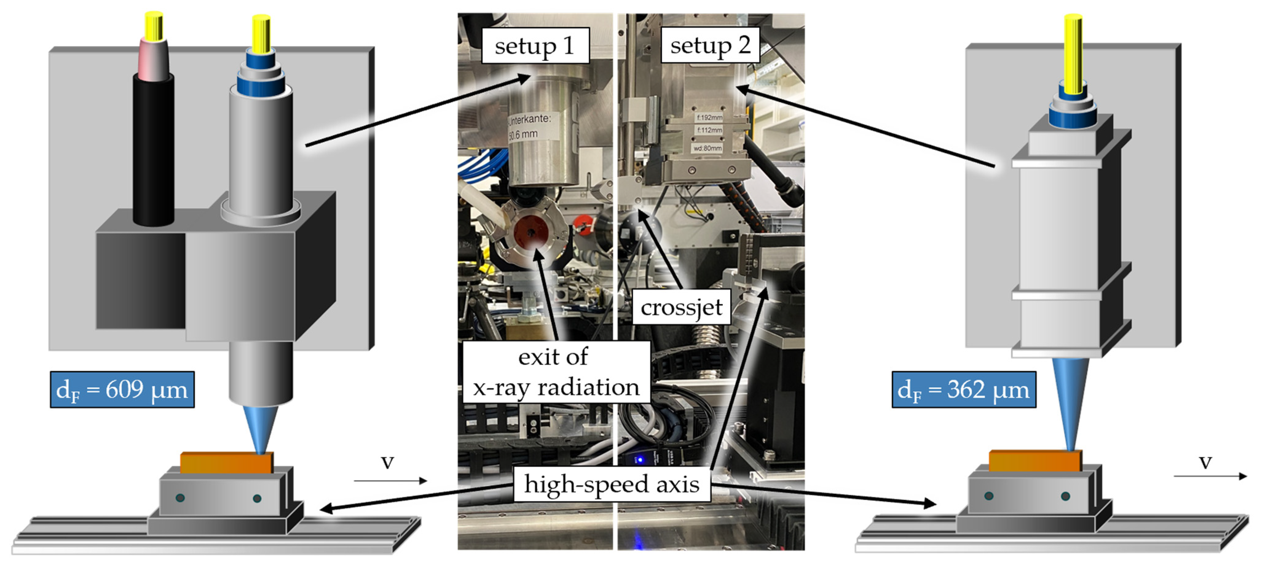
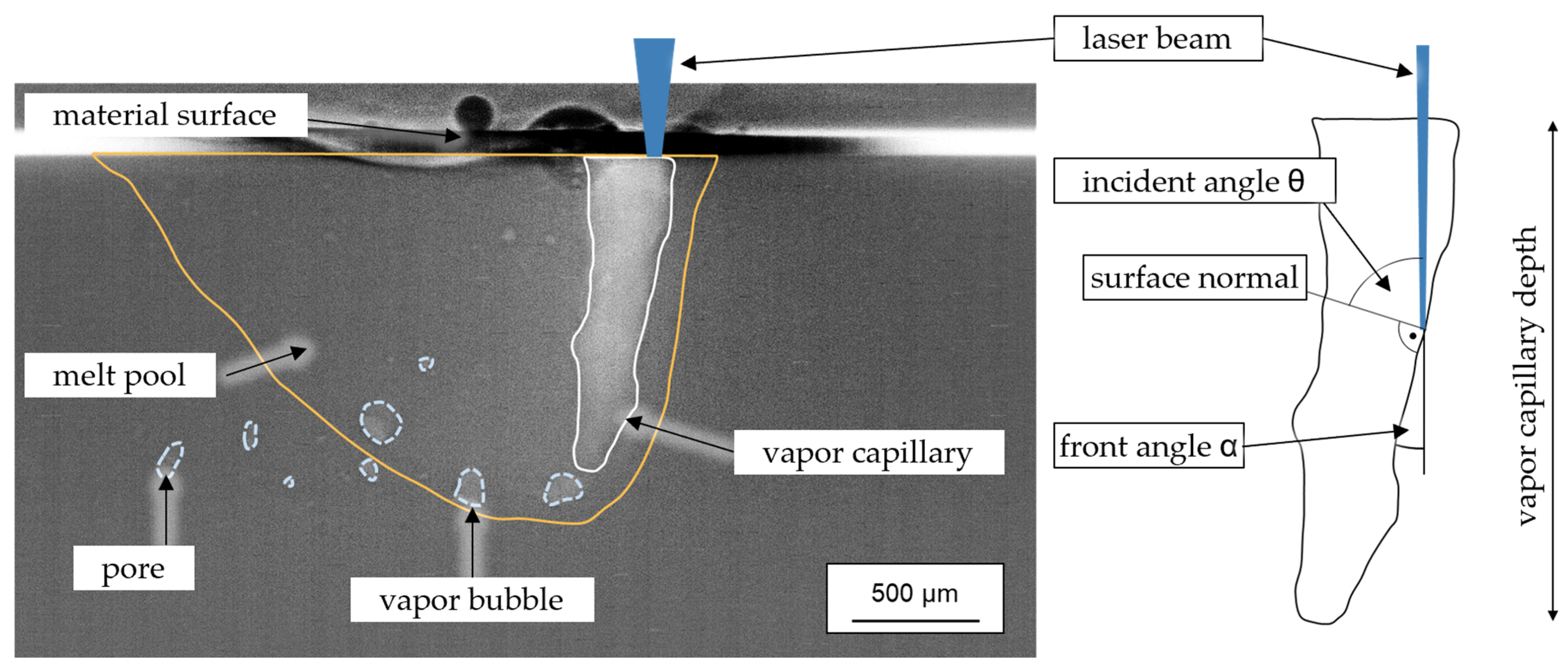
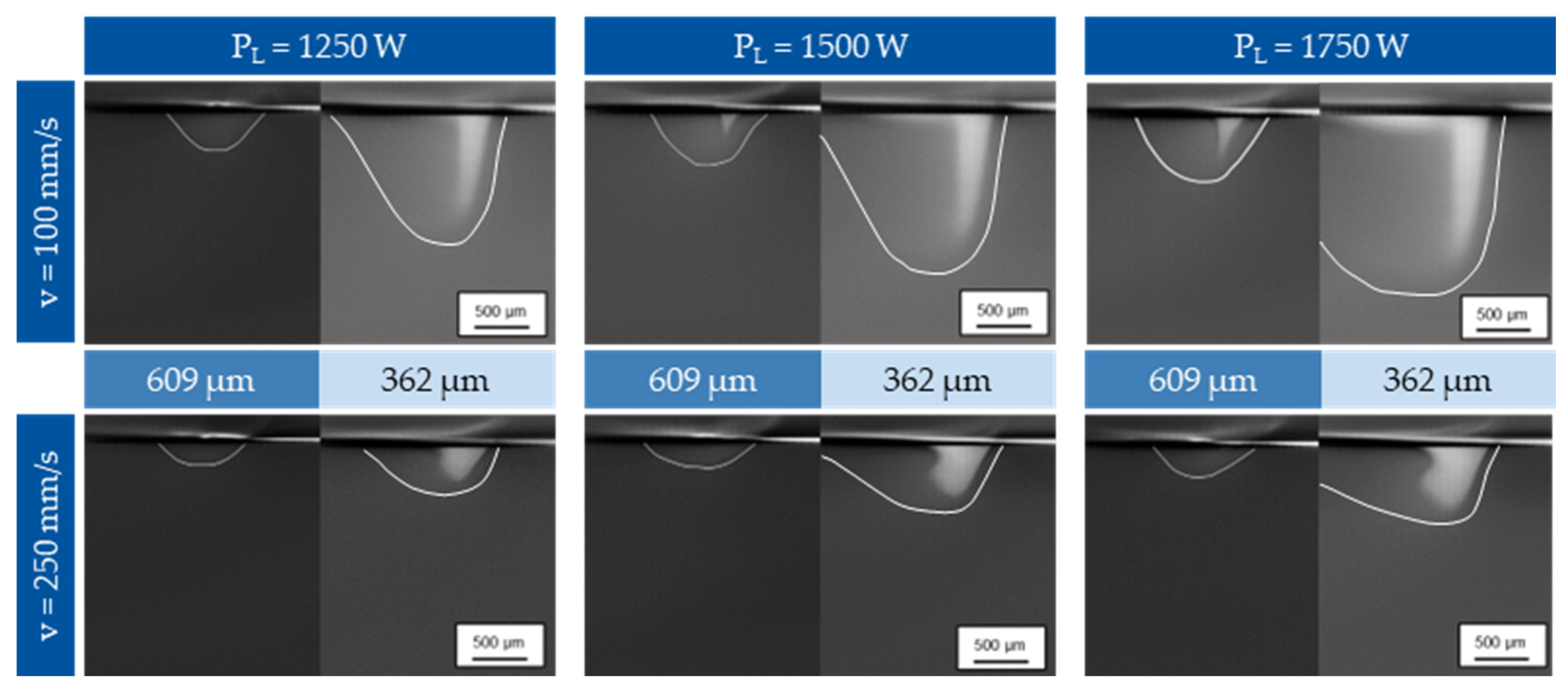
  • Investigation of vapor capillary geometry (opening and front angle) and welding depth during the laser beam welding of CuSn6 with a wavelength of 445 nm and a maximum output power of 1750 W at focal diameters of 362 µm and 609 µm.
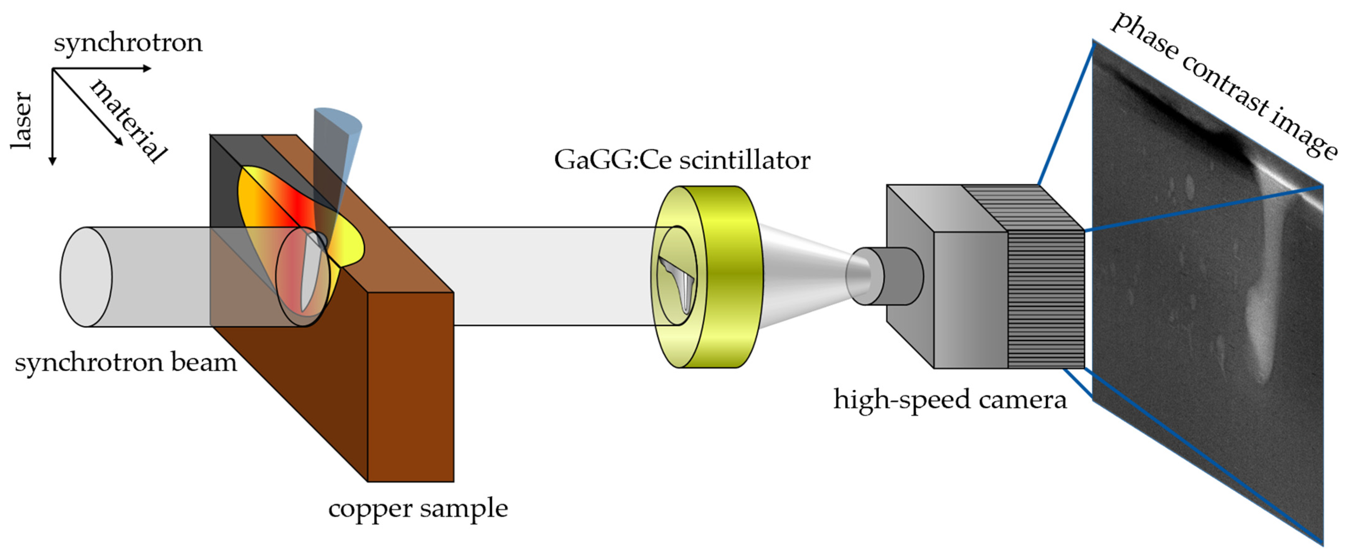
  • Analysis of phase-contrast images obtained by synchrotron radiation using automated evaluation by machine learning algorithms and determination of the process-parameter influence on the process dynamics.
By evaluating the data and simultaneously adjusting the process parameters, such as focal diameter dF, laser power PL, and feed rate v, the formation of the vapor capillary can be analyzed and its influence on the quality of the weld seam determined.

2. Materials and Methods

The welding experiments on CuSn6 were performed with a blue diode laser from Laserline with a wavelength of 445 nm and a maximal output power of 1800 W. The welding experiments involved bead-on-plate welds on a specimen geometry with dimensions of 100 mm × 30 mm × 2 mm, in accordance with Figure 1 and Figure 2. To investigate the influence of two different beam diameters for laser welding of CuSn6 samples, two different optical systems were used. The first optics is an in-house built optical system; a spot diameter of approximately 0.6 mm is achieved here. The original application of the optical system is dual welding with two laser beams with wavelengths of 445 nm and 1070 nm. However, the system can also be used to use only one of the two wavelengths. The second optics (OTS5), which was used in the second setup, was developed and is industrially distributed by Laserline. Here, a focal diameter of 362 µm is achieved. The optical properties of the two systems are summarized in Table 1. All welding experiments were conducted in the focal position z = 0. For the determination of the beam diameters, beam caustics, and beam characteristics, the FocusMonitor (FM+) from the company PRIMES was used.
Beside the laser beam sources and optical systems to focus the laser beam, the experimental setup for the investigations was based on the usage of the high-energy beamline P07 (EH4) of Petra 3 at Deutsches Elektronen Synchrotron (DESY) in Hamburg, Germany, which is operated by Helmholtz-Zentrum Hereon. To observe the welding process, X-ray radiation was transmitted through the copper sample and converted into visible light by a GaGG:Ce (Gadolinium Aluminium Gallium Garnet (Ce)) scintillator, as shown in Figure 1.
Using an ixCamera iSpeed 727, the glow of the scintillator, which was exposed to the X-ray radiation, was recorded. The pictures were taken with a resolution of 1600 × 900 pixels and a frame rate of 5 kHz. The corresponding parameters and properties of the synchrotron imaging setup are given in Table 2.
The experimental setup included, in both setups, a Jenny Science high-speed axis (LINAX Lxs 520F60) to apply the welding speed and a cross-jet to protect the optics from process spatters due to the relatively small working distances of less than 85 mm. To determine the maximum available laser power, a Primes Cube M was used to calibrate the laser power output with an accuracy of ±3%. The actual experimental setup is shown in Figure 2. To facilitate commissioning on site and to be able to easily swap between the two systems, the setups were mounted together on the fixture.
The synchrotron images obtained after the welding tests were then processed by shading and post-processing the individual images. This allows the melt pool, vapor capillary, bubble, and pore formation, as well as effects on the material surface, such as melt ejections, to be visualized in more detail. These process characteristics are shown in Figure 3.
In the context of this publication, the focus of the investigations will be on the geometry of the vapor capillary in addition to the transition from heat conduction welding to deep penetration welding. In addition to the wavelength as a variable for the power absorbed in the material, the angle of incidence of the laser radiation in the vapor capillary also plays a decisive role for the absorption. Studies have already been carried out using synchrotron radiation as an analysis tool for the incident angle α when welding with 515 nm and 1030 nm wavelengths [14]. Accordingly, the formation of the front angle and the vapor capillary depth when varying laser power and feed rate with a laser of 445 nm will be examined. The evaluation is supported by a trained neuronal network to automatically extract the desired process information from the image data.

3. Results and Discussions

First, experiments on power ramping with different beam diameters on CuSn6 are examined to determine the vapor capillary depth and front angle while varying laser power PL and feed rate v, as this material is used in many electromobility applications. In the second part, welds are examined, in which the laser power PL and the feed rate v are kept constant over the entire welding distance. By using mean value images, an impression of the fluctuation of the vapor capillary, if present, is to be gained.

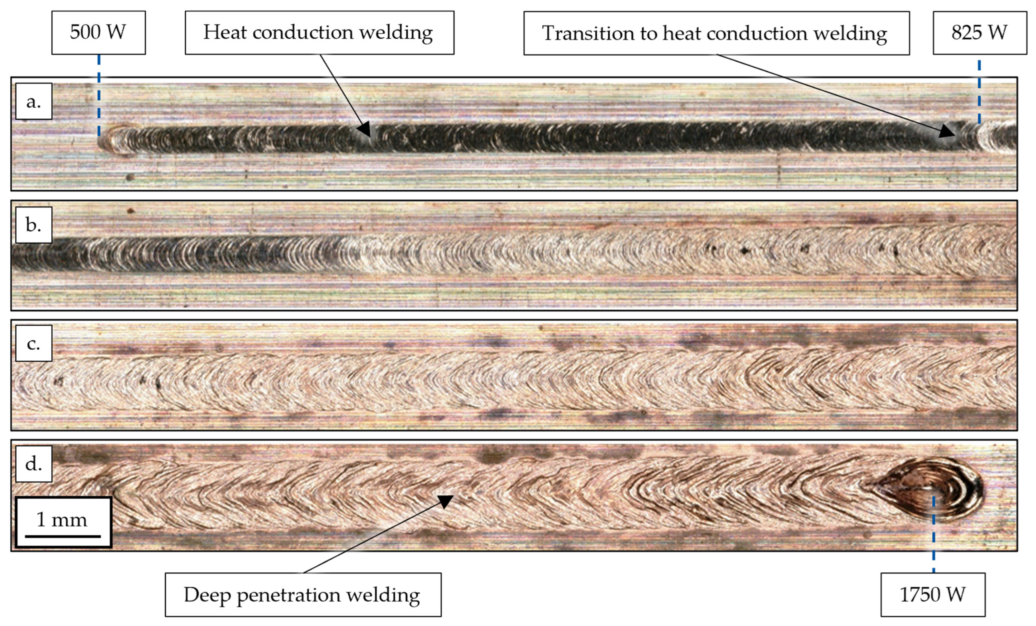
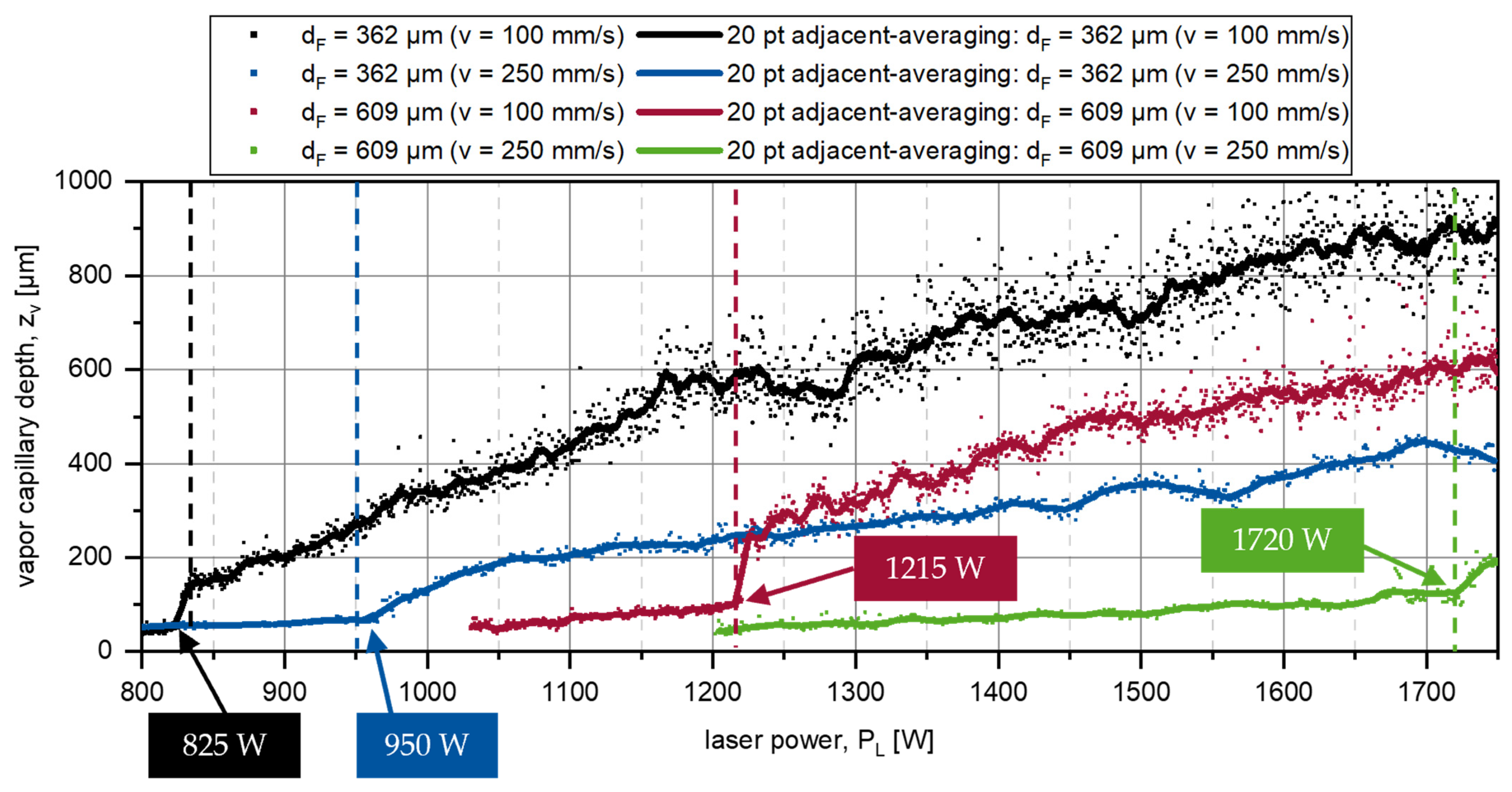
3.1. Laser Power Ramping

Figure 4 shows the top view of a weld on CuSn6 with a focal diameter of 362 µm. The letters in the figure describe a continuous weld seam with a feed direction from the left side in Figure 4a to the end crater on the right in Figure 4d. At a constant welding speed of 100 mm/s, the power was increased linearly from 500 W to 1750 W with a power increase of 25 W/mm. After the process was started, a mirror-like surface quality was achieved in the area of heat conduction welding. At a power of 825 W, corresponding to an intensity of 6.3 × 10⁵ W/cm2, the synchrotron data show that a small vapor capillary emerged, marking the start of the transition to deep penetration welding. At this point, the weld seam surface in Figure 4 also undergoes an initial change, which announces the change of welding regimes. After this threshold was reached, the vapor capillary depth increased with increasing power, transforming from a lens-shaped geometry into a more and more cone-shaped keyhole. Due to the increasing fluctuation of the vapor capillary towards higher laser powers, the surface roughness of the weld seam surface also increased.
The vapor capillary depth data evaluated by the neural network for the two focal diameters and feed rates of 100 mm/s and 250 mm/s are shown in Figure 5.
Due to fluctuations in the process and an evaluation-side standard deviation, point clouds of the welding depth were extracted from the shaded synchrotron images. The data were fitted by using an adjacent-averaging method, in which 20 adjacent points were considered for each value. With the same parameters as in Figure 4 (OTS 5, v = 100 mm/s), a steep increase in the vapor capillary depth zv can be observed at a power of 825 W, at which point the transition from heat conduction to deep penetration welding takes place. Towards a higher feed rate of 250 mm/s, the start of the transformation shifts to 950 W, and an intensity of 7.2 × 10⁵ W/cm2 is needed. Despite a 2.5-fold feed rate v, a factor of 1.14 higher intensity is required for the transition to deep penetration welding. The slight difference can be attributed to heat build-up in the material. A comparison of the two graphs shows that there is a higher vapor capillary depth fluctuation at a lower feed rate of 100 mm/s compared to 250 mm/s. This is due to the fact that the opening width of the vapor capillary increases towards higher velocities (compare Figure 6), the front angle becomes flatter, and the metal vapor can escape from the capillary. The opening of the capillary is also shown by Fetzer et al. [18]. With narrow vapor capillary channels, local temperature and pressure hotspots form, which lead to increased fluctuation of the vapor capillary. Comparing different beam diameters at the same feed rate of 100 mm/s in Figure 5, the transition to deep penetration welding takes place at a power of 1215 W for the bigger 609 µm spot diameter. Although more power is required here, the transition to deep penetration welding already takes place at an intensity of 3.3 × 10⁵ W/cm2, which corresponds to a reduction by a factor of 1.9. This is probably since the larger beam diameter allows more radiation to initially enter the capillary, as the vapor capillary has a larger opening and flatter front angle, similar to higher feed rates (compare Figure 6), in combination with heat accumulation. Again, the fluctuation of the vapor capillary depth is less than with a small focal diameter and low velocities. The front angle in the deep penetration welding regime, which is described in Figure 3, over the laser power for the four investigated parameters is shown in Figure 7.
The diagram shows that the lowest front angle can be achieved when the smallest focal diameter, in combination with the lowest velocity, is selected. A small front angle means that a narrow vapor capillary is formed, and the energy can be transported deep into the material due to multiple reflections at the capillary walls. The relationship between absorption and reflection in dependency of the angle of incidence was described by Kaufmann et al. [15]. The front angle increases towards higher speeds or the larger spot diameter. Due to the higher speed, the laser beam is relatively further in front of the capillary. As a result, less radiation is absorbed in the vapor capillary, less vaporization occurs, the opening pressure is reduced, and the capillary becomes flatter. However, the flatter capillary results in higher absorption according to Fresnel. These points lead to a cycle until equilibrium is achieved. By combining the data from Figure 5 and Figure 7, the vapor capillary depth zv can be plotted over the front angle α (see Figure 8).
The diagram illustrates that a small front angle α leads to more energy being reflected deep into the material, and a greater welding depth zv can be achieved. However, depending on the setup, the same vapor capillary depths zv can also be achieved with different front angles α. At a constant feed rate of 100 mm/s, for example, a vapor capillary depth zv of around 500 µm can be achieved if a front angle α of 19.7° is achieved with a focal diameter of 362 µm or a front angle α of 29.3° with a focal diameter of 609 µm. Although more power is required to achieve the same welding depth when using a larger spot diameter, the larger front angle means that the metal vapor can escape better, resulting in the vapor capillary stabilizing and fewer process fluctuations.

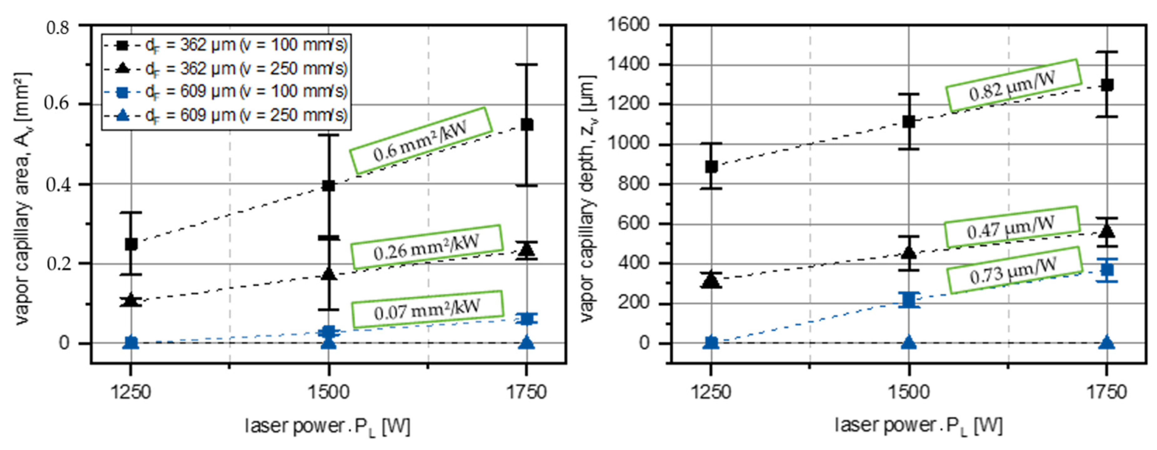
3.2. Welding with Constant Laser Power PL and Feed Rate v

By superimposing all images of a single welding experiment with constant laser power PL and feed rate v, so-called mean value images can be generated. This allows the sharpness of the vapor capillary edges in the images to visualize how strongly the processes fluctuate and to determine the main position and geometry of the vapor capillary. Furthermore, the averaged image describes the position and geometry of the vapor capillary in the process. Figure 6 shows average images of the processes with constant laser powers PL, feed rates v, and beam diameters dF.
At a feed rate v of 100 mm/s and a spot diameter of 362 µm, a small front angle α is given, which causes the radiation to be reflected deep into the vapor capillary. The resulting high process dynamics induced by hot spots in the narrow capillary blur the edges of the vapor capillary in the mean value images. If the focal diameter of 609 µm is considered, a stable deep penetration welding process occurs later, while at lower laser power, the melt pool in heat conduction welding can be observed. The edges of the mean value image are sharp, which indicates a stable vapor capillary. Looking at the higher speed of 250 mm/s, it is noticeable that no vapor capillary is formed up to 1750 W using a larger spot diameter of 609 µm. With an intensity of 4.7 × 10⁵ W/cm2, only a melt pool is formed. With the smaller focus diameter of 362 µm, deep penetration welding is also achieved at a feed rate of 250 mm/s. The mean value image shows relatively sharp edges in the area of the vapor capillary, which means that a stable vapor capillary can be assumed. Furthermore, when looking at the front angle α, it is noticeable that the vapor capillary length in feed direction is drawn wider due to the higher feed rate. This again has the advantage during the welding process that the metal vapor can escape better from the capillary channel.
Since both the vapor capillary depth and width can be influenced by changing the focal diameter dF and the feed rate v, the area of the vapor capillary Av extracted by the neuronal network is also shown in Figure 9 in addition to the vapor capillary depth zv.
The error bars describe the minimum and maximum values determined by the neural network after the process is settled. At a feed rate v of 100 mm/s and a focal diameter dF of 362 µm, the welding depth increased linearly by approximately 0.82 µm/W. At a feed rate v of 250 mm/s, this increase is reduced to 0.47 µm/W. If the focal diameter dF is varied instead of the feed rate, welding depth increases by 0.73 µm/W in the range of 1500 W to 1750 W. At the largest focal diameter dF and the highest feed rate v, there is no vapor capillary formation, as was seen in the mean value images. The vapor capillary areas Av also follow an approximately linear curve at the three power levels. As an example, with a spot diameter of 362 µm and a feed rate of 100 mm/s, the area of the vapor capillary increases more than twice as much as at a feed rate of 250 mm/s. Here, due to the lower distance energy, less energy can be used locally to build up the capillary. Although the width of the vapor capillary opening increases towards high feed rates v, the front angle α is larger and the depth of the vapor capillary is considerably smaller. Whether the vapor capillary depths zv and the area Av really follow a linear progression must be determined by further experiments towards higher outputs.

4. Conclusions

In this work, X-ray phase contrast observations of the laser beam welding process of CuSn6 using a 445 nm blue diode laser and two different focal diameters were performed. By means of synchrotron images, the transition from heat conduction welding to deep penetration welding could be observed.
For this purpose, experiments were carried out with power ramps from 500 W to 1750 W at focal diameters of 362 µm and 609 µm and at feed rates of 100 mm/s and 250 mm/s. To describe the process dynamics, the vapor capillary was then described in terms of its depth zv and front angle α. The following conclusions are drawn for the experiments:
  • For a welding speed of 100 mm/s and a focal diameter of 362 µm, the transition from heat conduction welding to deep penetration welding takes place at an intensity of about 6.3 × 10⁵ W/cm2;
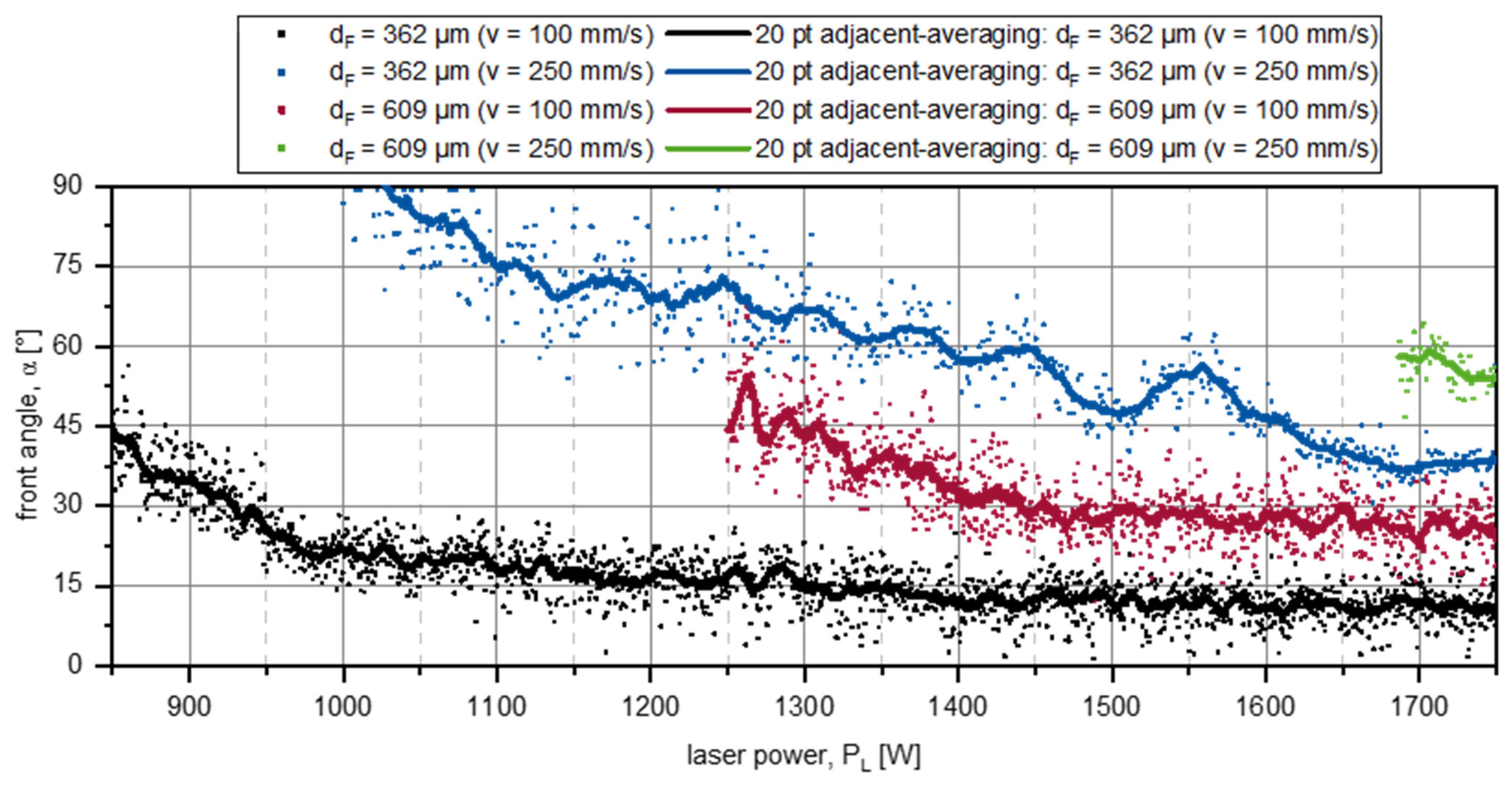
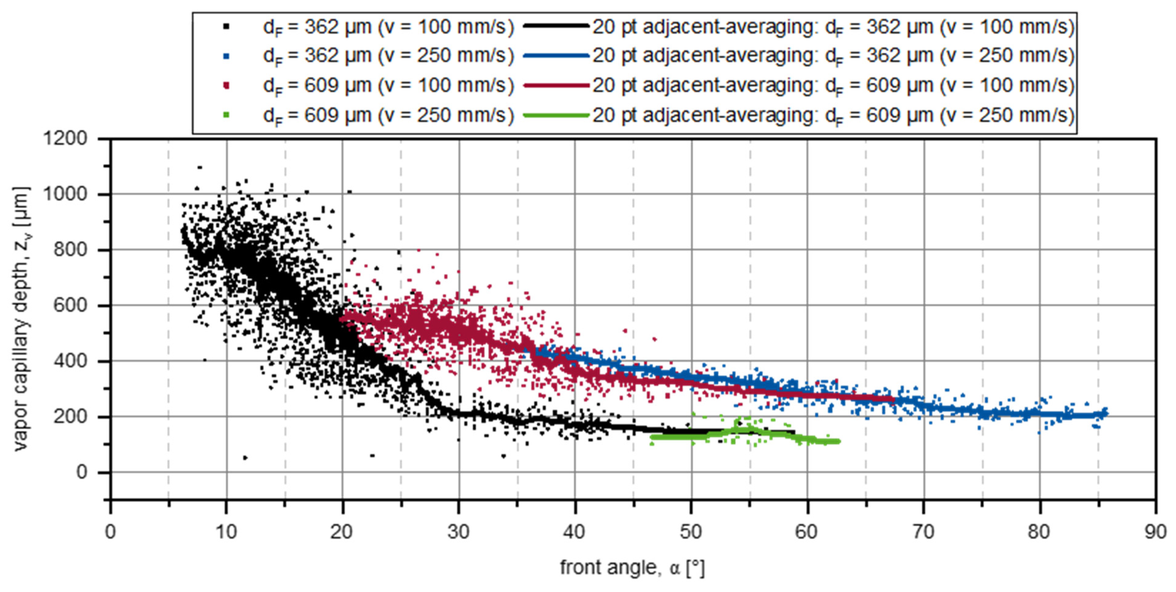
  • Increasing the intensity on a basis of the laser power during deep penetration welding with a focal diameter dF of 362 µm and a small front angle α leads to an increase of the vapor capillary, corresponding turbulences, pulsations at the bottom of the capillary, and pores;
  • Fewer pores are observed during synchrotron trials with higher welding speeds (250 mm/s) due to a higher front angle α inducing a beneficial vapor evaporation, and expulsions leave at the top instead of building pores;
  • When using a larger focal diameter dF, more laser power PL is required to achieve the threshold intensity, but the larger spot diameter results in a wider capillary opening with a larger front angle α being beneficial for the stabilization of the vapor capillary.
Additionally, welding tests with only constant parameters were carried out to further describe the vapor capillary stability and geometry. All process images of one parameter each were used to generate mean value images. The sharpness of the edges and the contrasts displayed allow conclusions to be drawn about the fluctuations, position, and geometry of the vapor capillary. Finally, a parameter space is presented that describes the vapor capillary depth zv and area of the capillary Av in dependency of the beam diameter dF, the feed rate v and the laser power PL.
In sum, laser welding of CuSn6 enables a stable deep penetration welding process with welding depths > 1 mm with the correct setting of the beam diameter dF, feed rate v, and laser power PL. This results in a front angle α as a result of the parameter selection. The targeted enlargement of the vapor capillary opening by increasing the focus diameter or the feed rate enables less fluctuation to be achieved, as pressure hotspots are minimized by better evaporation from the vapor capillary. With increasing laser power, the use of blue laser radiation has the potential to scale these effects and to reduce the formation of weld seam defects due to vapor capillary fluctuations at even greater welding depths.
Accordingly, further investigations should be carried out in the future regarding varying focal diameters dF and increasing feed rates v in order to analyze their influence on the front angle α in more detail. The aim is to produce a customized capillary geometry with the greatest possible welding depths, resulting in a defect-free weld seam with low surface roughness. At the time of these investigations, the experiments had to be limited to a maximum laser power of 1800 W. By using beam sources and optics with an output power of about 4 kW and a minimum spot size of 300 µm, which are currently being developed, the experiments will be continued.

Author Contributions

Conceptualization, C.S., F.D. and M.H.; methodology, C.S., F.D. and M.H.; software, F.D.; validation, C.S.; formal analysis, C.S. and F.D.; investigation, C.S., F.D. and M.H.; resources, C.S., M.H., A.G., F.B., J.M. and C.H.; data curation, C.S.; writing—original draft preparation, C.S.; writing—review and editing, C.S. and M.H.; visualization, C.S. and F.D.; supervision, A.G., F.B., J.M. and C.H.; project administration, C.S. and A.G.; funding acquisition, A.G. and C.H. All authors have read and agreed to the published version of the manuscript.

Funding

The presented investigations were carried out at RWTH Aachen University within the framework of the Collaborative Research Centre SFB1120-236616214 “Bauteilpräzision durch Beherrschung von Schmelze und Erstarrung in Produktionsprozessen” and funded by the Deutsche Forschungsgemeinschaft e.V. (DFG, German Research Foundation). The sponsorship and support is gratefully acknowledged.

Data Availability Statement

The data that support the findings of this study are available upon reasonable request. Selected data are available after authorization in Coscine with the persistent identifier (PID) http://hdl.handle.net/21.11102/9d5f2232-f9a7-495d-a1ce-0c67b57c169b (accessed on 16 February 2024). For more information, please contact the corresponding author.

Conflicts of Interest

The authors declare no conflicts of interest.

References

  1. Häusler, A. Präzisionserhöhung Beim Laserstrahl-Mikroschweißen Durch Angepasstes Energiemanagement. Ph.D. Thesis, RWTH Aachen University, Aachen, Germany, 2020. [Google Scholar] [CrossRef]
  2. Hummel, M.; Schöler, C.; Häusler, A.; Gillner, A.; Poprawe, R. New approaches on laser micro welding of copper using a laser beam source with a wavelength of 450 nm. J. Adv. Join. Process. 2020, 1, 100012. [Google Scholar] [CrossRef]
  3. Rütering, M. Blue Diode Laser Revolutionizes Copper Processing. Laser Focus World (5 August 2022). Available online: https://www.laserfocusworld.com/laser-processing/article/14276425/blue-diode-laser-revolutionizes-copper-processing (accessed on 20 December 2023).
  4. Wang, H.; Kawahito, Y.; Yoshida, R.; Nakashima, Y.; Shiokawa, K. Development of a high-power blue laser (445 nm) for material processing. Opt. Lett. 2017, 42, 2251–2254. [Google Scholar] [CrossRef] [PubMed]
  5. Morimoto, K.; Tsukamoto, M.; Masuno, S.; Sato, Y.; Azumi, K.; Hayashi, Y.; Abe, N. Copper Plate Welding with 100 W Blue Diode Laser. In Proceedings of the LIA Conference, Orlando, FL, USA, 14–18 October 2018; Available online: https://pubs.aip.org/lia/liacp/proceedings/ICALEO/2018/P116/397618 (accessed on 20 December 2023).
  6. Silva Sa, M.; Finuf, M.; Fritz, R.; Tucker, J.; Pelaprat, J.-M.; Zediker, M.S. Blue Diode Laser Diode (450 nm) Systems for Welding of Copper. In Proceedings of the SPIE 10514, High-Power Dioder Laser Technology XVI, 1051407, San Francisco, CA, USA, 19 February 2018. [Google Scholar] [CrossRef]
  7. Baumann, M.; Black, A.; Malchus, J.; Chacko, R.V.; Marfels, S.; Witte, U.; Dinakaran, D.; Ocylok, S.; Weinbach, M.; Bachert, C.; et al. 1000 W blue fiber-coupled diode-laser emitting at 450 nm, In Proceedings of SPIE 10900, High-Power Diode Laser Technology XVII, 1090005, San Francisco, CA, USA, 4 March 2019. [CrossRef]
  8. Takenaka, K.; Sato, Y.; Fujio, S.; Nishida, K.; Rika, I.; Hori, E.; Kato, S.; Suwa, M.; Uno, S.; Tojo, K.; et al. Bead-on-plate welding of pure copper with a 1.5-kW high-power blue diodelaser. Weld World 2023, 67, 99–107. [Google Scholar] [CrossRef]
  9. Sato, Y.; Sudo, M.; Fujio, S.; Takenaka, K.; Mizutani, M.; Tsukamoto, M. Experimental study on pure copper welding with the 1.5 kW blue diode laser for realization of a carbon-neutral society. In Proceedings of SPIE 12403, High-Power Diode Laser Technology XXI, 124030Q, San Francisco, CA, USA, 14 March 2023. [Google Scholar] [CrossRef]
  10. Britten, S.; Schmid, L.; Molitor, T.; Rütering, M. Blue high-power laser sources for processing solutions in e-mobility and beyond. Procedia CIRP 2020, 94, 592–595. [Google Scholar] [CrossRef]
  11. Liverani, E.; Ascari, A.; Tomesani, L.; Fortunato, A. From conduction to keyhole transition on copper using blue laser: Bead-on-plate process modeling and analysis of physical phenomena. J. Mater. Process. Technol. 2023, 316, 117953. [Google Scholar] [CrossRef]
  12. Iqbal, N.; Sadeghian, A. Fundamental study of blue wavelength laser for welding low thickness dissimilar Cu and steel materials. Mat. Today Commun. 2023, 36, 106604. [Google Scholar] [CrossRef]
  13. Tang, Z.; Wan, L.; Yang, H.; Ren, P.; Zhu, C.; Wu, Y.; Wang, H.; Wang, H. Stable conduction mode welding of conventional high-reflectivity metals with 2000 W blue laser. Opt. Laser Technol. 2023, 168, 109971. [Google Scholar] [CrossRef]
  14. Hummel, M.; Meier, C.; Olowinsky, A.; Gillner, A.; Beckmann, F.; Moosmann, J.; Häfner, C. In situ synchrotron observation of the vapor capillary geometry in laser welding of copper with 1030 nm and 515 nm laser beam sources. In Proceedings of the SPIE 12414, High-Power Laser Materials Processing: Applications, Diagnostics, and Systems XII, 124140A, San Francisco, CA, USA, 15 March 2023. [Google Scholar] [CrossRef]
  15. Kaufmann, F.; Forster, C.; Hummel, M.; Olowinsky, A.; Beckmann, F.; Moosmann, J.; Roth, S.; Schmidt, M. Characterization of Vapor Capillary Geometry in Laser Beam Welding of Copper with 515 nm and 1030 nm Laser Beam Sources by Means of In Situ Synchrotron X-ray Imaging. Metals 2023, 13, 135. [Google Scholar] [CrossRef]
  16. Chung, W.-S.; Hummel, M.; Spurk, C.; Häusler, A.; Olowinsky, A.; Häfner, C.; Beckmann, F.; Moosmann, J. In Situ X-ray phase contrast imaging of the melt and vapor capillary behavior during the welding regime in transition on aluminum with limited material thickness. Weld. World 2023, 68, 43–50. [Google Scholar] [CrossRef]
  17. Heine, L.; Schlett, M.; Britten, S.; Arndt, A.; Spurk, C.; Hummel, M.; Beckmann, F.; Moosmann, J. Blue diode lasers–Understanding and influencing melt pool dynamics in copper. J. Laser Appl. 2023, 35, 4. [Google Scholar] [CrossRef]
  18. Fetzer, F.; Hagenlocher, C.; Weber, R. High Power, High Speed, High Quality. Laser Tech. J. 2018, 15, 3. [Google Scholar] [CrossRef]
Figure 1. Alignment of synchrotron beam, laser beam, copper sample, and high-speed camera to each other during a synchrotron experiment.
Jmmp 08 00047 g001
Figure 2. Experimental setups used at Deutsches Elektronen Synchrotron (DESY) Petra 3 P07; Custom Optics with dF = 609 µm (left); Laserline OTS5 with dF = 362 µm (right).
Jmmp 08 00047 g002
Figure 3. Phase contrast image of deep penetration welding and geometrical description of the vapor capillary.
Jmmp 08 00047 g003
Figure 4. Top view of a continuous weld seam from image (ad) on CuSn6 with power ramping from 500 W to 1750 W and a feed rate of 100 mm/s; dF = 362 µm (setup 2).
Jmmp 08 00047 g004
Figure 5. Vapor capillary depth zv during power ramping from 500 W to 1750 W determined by the evaluation of the high-speed images by neural networks.
Jmmp 08 00047 g005
Figure 6. Superimposed mean value images of a constant deep penetration welding process with varying focal diameters dF, laser powers PL and feed rates v.
Jmmp 08 00047 g006
Figure 7. Vapor capillary front angle α during power ramping from 500 W to 1750 W in deep penetration mode determined by the evaluation of the high-speed images by neural networks.
Jmmp 08 00047 g007
Figure 8. Correlation of vapor capillary depth zv and front angle α during power ramping from 500 W to 1750 W based on the results of Figure 5 and Figure 7.
Jmmp 08 00047 g008
Figure 9. Vapor capillary depths zv and areas Av during deep penetration welding with varying focal diameters dF, laser powers PL, and feed rates v.
Jmmp 08 00047 g009
Table 1. Characteristics of the two experimental setups.
Laser Beam CharacteristicSetup 1Setup 2
Laser beam sourceLaserline LDMblue 1800-30
Max. output power, Pmax1800 W
Wavelength, λ445 nm
Optical systemCustom OpticsLaserline OTS 5
Focal diameter, dF609 µm362 µm
Rayleigh length, zR2.68 mm1.13 mm
Beam quality, M2233.98203.1
Beam parameter product38 mm∙mrad33 mm∙mrad
Table 2. Parameters and properties of the synchrotron imaging setup.
ParameterUnitP07 Petra III
Operation mode-High Beta
Photon energykeV89
Synchrotron beam areamm22 × 2
Scintillator material-GaGG:Ce
Scintillator sizemm211 × 11
Scintillator thicknessµm1200
Disclaimer/Publisher’s Note: The statements, opinions and data contained in all publications are solely those of the individual author(s) and contributor(s) and not of MDPI and/or the editor(s). MDPI and/or the editor(s) disclaim responsibility for any injury to people or property resulting from any ideas, methods, instructions or products referred to in the content.

