Article

Crack-Free Joining of High-Strength AA7055 Sheets by Friction Based Self-Piercing Riveting with the Aid of Numerical Design

1
Oak Ridge National Laboratory, Materials Science and Technology Division, Oak Ridge, TN 37831, USA
2
School of Mechanical and Electrical Engineering, Soochow University, Suzhou 215006, China
*
Author to whom correspondence should be addressed.
Former employee.
J. Manuf. Mater. Process. 2023, 7(6), 216; https://doi.org/10.3390/jmmp7060216
Submission received: 26 October 2023 / Revised: 29 November 2023 / Accepted: 30 November 2023 / Published: 1 December 2023

Abstract

:
Unique friction-based self-piercing riveting (F-SPR) was employed to join high-strength, low-ductility aluminum alloy 7055 for lightweight vehicle applications. This study aimed to maximize the joint strength of the AA7055 F-SPR joint while avoiding cracking issues due to low ductility at room temperature. A fully coupled Eulerian–Lagrangian (CEL) model was employed to predict the process temperature during F-SPR, and the temperature field was then mapped onto a 2D axisymmetric equivalent model for accelerated numerical analysis. The geometry, dimensions, and material strength of the rivet, as well as the depth of the die cavity and plunging depth, were investigated to enhance joint formation. Also, a static finite-element analysis model was developed to predict and analyze the stress distribution in the rivet under different mechanical testing loading conditions. Overall, the numerical model showed good agreement with the experiment results, such as joint formation and mechanical joint strength. With the aid of virtual fabrication through numerical modeling, the joint design iterations and process development time of F-SPR were greatly reduced regarding the goal of lightweight, high-strength aluminum joining.

1. Introduction

Joining lightweight materials is a critical technique for achieving carbon neutrality and energy saving [1]. Among several lightweight materials, such as magnesium (Mg), carbon fiber-reinforced plastics (CFRP), aluminum (Al) alloy, and advanced/ultra-high-strength steels, high-strength Al alloy offers a good balance of cost, strength, and recyclability [2]. It is known that Al alloys have the second largest portion of applications in automotive body structures. Furthermore, die-casting technology has recently enabled the fabrication of full Al structures. However, low ductility at room temperature causes cracking issues when conventional mechanical fastening joining (e.g., self-piercing riveting) is used. To join the high-strength, low-ductility Al sheets without cracking issues, unique solid-state joining methods, such as ultrasonic spot welding [3,4] and friction stir (spot) welding [5], have been developed. These techniques make use of axial compression load and shear deformation to form a sound joint for materials like Mg alloy and Al alloy. Furthermore, several variations in FSW have been proposed for specific spot-joining applications. For example, friction bit joining (FBJ) [6,7,8,9] has been successfully employed to join high-strength Al alloy and CFRP to dual-phase steels. It has also been combined with adhesive bonding to enhance the mechanical strength of Al/steel and CFRP/steel joints and improve galvanic corrosion resistance in dissimilar material joints. Friction stir blind riveting (FSBR) [10,11] was developed by using a high-speed rotating blind rivet to penetrate sheets. Consistent joint strength and fatigue life were obtained over a wide process window.
Friction-based self-piercing riveting (F-SPR) [12] is another promising spot-welding technology used to avoid cracking issues in low-ductility materials at room temperature by utilizing frictional heat during joining. Under heat effects from friction and plastic work, the strength and ductility of the joined materials as well as the required tool force of the F-SPR process will be very different from those of self-piercing riveting (SPR) [13]. Liu et al. [14] investigated the effects of rivet rotating speed and plunge rate on plunge force, torque, and joint strength for joining high-strength Al alloy AA7075-T6 to Mg alloy AZ31B. It was concluded that a higher rotating rate and slower punch speed can reduce axial force and torque. Ma et al. [15,16] compared the performance of the SPR and F-SPR processes in joining Al alloy AA5182-O sheets. They found that tool force is much reduced in F-SPR. Mechanical performance and fatigue life were improved because of the increased local hardness of the aluminum due to grain refinement and the formation of solid-state joining. Furthermore, recent efforts to join various lightweight multi-materials as a single class have been made in the framework of the Joining Core Program funded by the U.S. Department of Energy, Vehicle Technology Offices [17,18,19].
For any given material’s strength/ductility at room temperature, material combination, sheet thickness, and stack-up sequences (e.g., 2T or 3T), the joining process window needs to be optimized with respect to both rivet and die designs. Nevertheless, current experimental designs basically rely on trial-and-error procedures dealing with a variety of processing parameters. For instance, to facilitate mechanical interlocking, which has a critical role in mechanical joint performance, the rivet should have an appropriate tip angle and adequate strength relative to the base materials being joined. The flaring of the rivet is also influenced by the depth of the die cavity and the depth of rivet penetration. On the other hand, the plunging speed and depth, as well as the rotating speed of the rivet [20], will impact the frictional heat generation that controls the material softening and solid-state joining.
Numerical modeling is a cost-effective way to predict joint formation under given process conditions and performance during mechanical loading. A large number of numerical studies have been carried out on the SPR process given the axisymmetric conditions. Huang et al. [21] studied the SPR processes of Al alloy 6111T4 and steel HSLA340 sheets with the LS-DYNA/explicit finite-element software. They derived rivet material properties by using the inverse modeling approach. The element erosion technique was also adopted to separate the upper sheet before the rivet penetrated the lower sheet. Residual stresses were investigated using LS-DYNA/implicit for spring-back analysis after explicit riveting simulation. Rusia and Weihe [22] proposed a five-stage simulation process chain to study the SPR process and the mechanical performance of the formed joint. A novel solid–shell interaction model, along with a stress–strain transfer approach, was developed for joint strength prediction. The inclusion of a damage model was found to be critical in modeling the force–displacement curve. Casalino et al. [23] developed a numerical model based on the LS-DYNA finite-element code to address complex multi-physics phenomena in the self-piercing riveting of two sheets of 6060T4 Al alloy. The element erosion technique was implemented to model fracture initiation and propagation using optimized fine mesh and an effective plastic strain threshold, and the “kill-element” technique was used to remove the element from the mesh to enable material separation. Deng et al. [24] investigated the SPR joining process of aluminum alloy 6061-T6 and mild steel SPFC340 sheets by using SIMFACT Forming. With the aid of a model, the tangential stress and the effective strain were simulated for joining with a flat-bottom die and a conical section die, and the joint strength and fractography of the coupons were compared experimentally. Karathanasopoulos et al. [25] developed a modeling approach based on Abaqus Explicit for the AA7075-to-AA2019 SPR process; the rivet and sheet material properties, such as stress–strain curves and fracture parameters, were characterized experimentally. More impressively, they revealed the that impact of rivet thickness and die depth is critical to joint quality. Bouchard et al. [26] employed the Forge finite-element code to model Al-to-steel SPR in a 2D configuration. A Lemaitre damage model was used to handle the material degradation during the SPR process, and the “kill element” technique was used for fractures. The simulation results of the process model were imported into a 3D mesh to perform shear test modeling.
Compared with SPR, F-SPR is not strictly axisymmetric given the high-speed rotation of the rivet. In addition, heat generation and thermal conduction must be simulated to account for frictional heat effects on material softening. Thus, the full-process numerical simulation of F-SPR is rarely seen in the literature. Ma et al. [27] established a three-dimensional (3D) thermomechanical-coupled finite-element (FE) model for the F-SPR process. Measured temperature-dependent material properties and a predefined crack region were used to model the material flow and failure. The transient analysis enables the observation of the dynamic formation of the F-SPR mechanical joint, stress, and temperature evolution. The 3D-coupled Eulerian–Lagrangian model has been successfully used to simulate linear friction stir welding (FSW), such as in the studies by Geng et al. [28] and Shokri et al. [29], revealing heat generation and material flow under different process conditions. Compared with the FSW process, the element size in modeling F-SPR is much smaller because of the existence of the tiny geometry features of rivet tips. Therefore, such fully coupled thermomechanical simulation is extremely time consuming, which is a problem for joining process optimization and tool design.
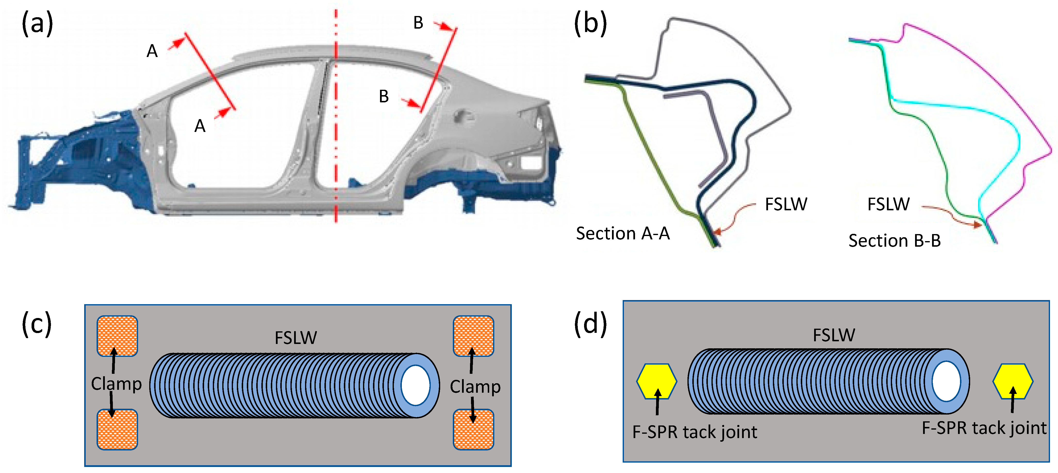
In the present study, a combined 3D-2D thermomechanical model was developed to predict temperature distribution and rivet flaring during F-SPR. Furthermore, performance models for lap–shear and cross-tension tests were also developed to predict the load–displacement relationship and failure mode of joints. The influence of rivet tip angle, material strength, and die cavity design on interlocking distance and joint failure load were investigated for high-strength, low-ductility Al alloy 7055. To streamline the experimental iterations of rivet design, a static numerical model was employed to refine rivet head height and shank diameter. Based on guidance from numerical modeling, the rivet and die were designed and fabricated for F-SPR process development. Joint formation and mechanical joint performance in the experiment were compared with numerical models. These research efforts aim to advance the F-SPR technique for joining multiple sheets and dissimilar material combinations while reducing the required complex clamping design and force, which can aid in friction stir linear welding (FSLW), as depicted in Figure 1. To cater to lightweight vehicle applications, a body-in-white (BIW) structure predominantly composed of Al alloy is suggested [30], as illustrated in Figure 1a. Given the favorable attributes associated with FSLW in working with Al alloys, including the achievement of defect-free joints, robust mechanical joint strength, and the ability to weld both similar and dissimilar aluminum alloys, it emerges as a suitable choice for the construction of the proposed new vehicle design. In this approach, FSLW facilitates continuous seam welding for structural integration. However, the conventional application of FSLW often necessitates intricate clamping designs and substantial force to securely hold the components during the joining process. This becomes particularly challenging when dealing with complex automotive parts (shown in Figure 1b), as implementing such clamping requirements becomes impractical, as presented in Figure 1c. In addressing this issue, F-SPR can function as a tack spot-joining technique, effectively securing BIW parts before the FSLW stage (Figure 1d). The added benefit of F-SPR lies in its ability to contribute supplementary mechanical joint strength alongside FSLW, ensuring a heightened level of joint strength that aligns with the stringent requirements for both strength and durability. The synergistic approach, via characterization and modeling efforts, will enable a better understanding of the joining mechanism and accelerate the development of the F-SPR process.

2. Modeling Approach and Experimental Setup

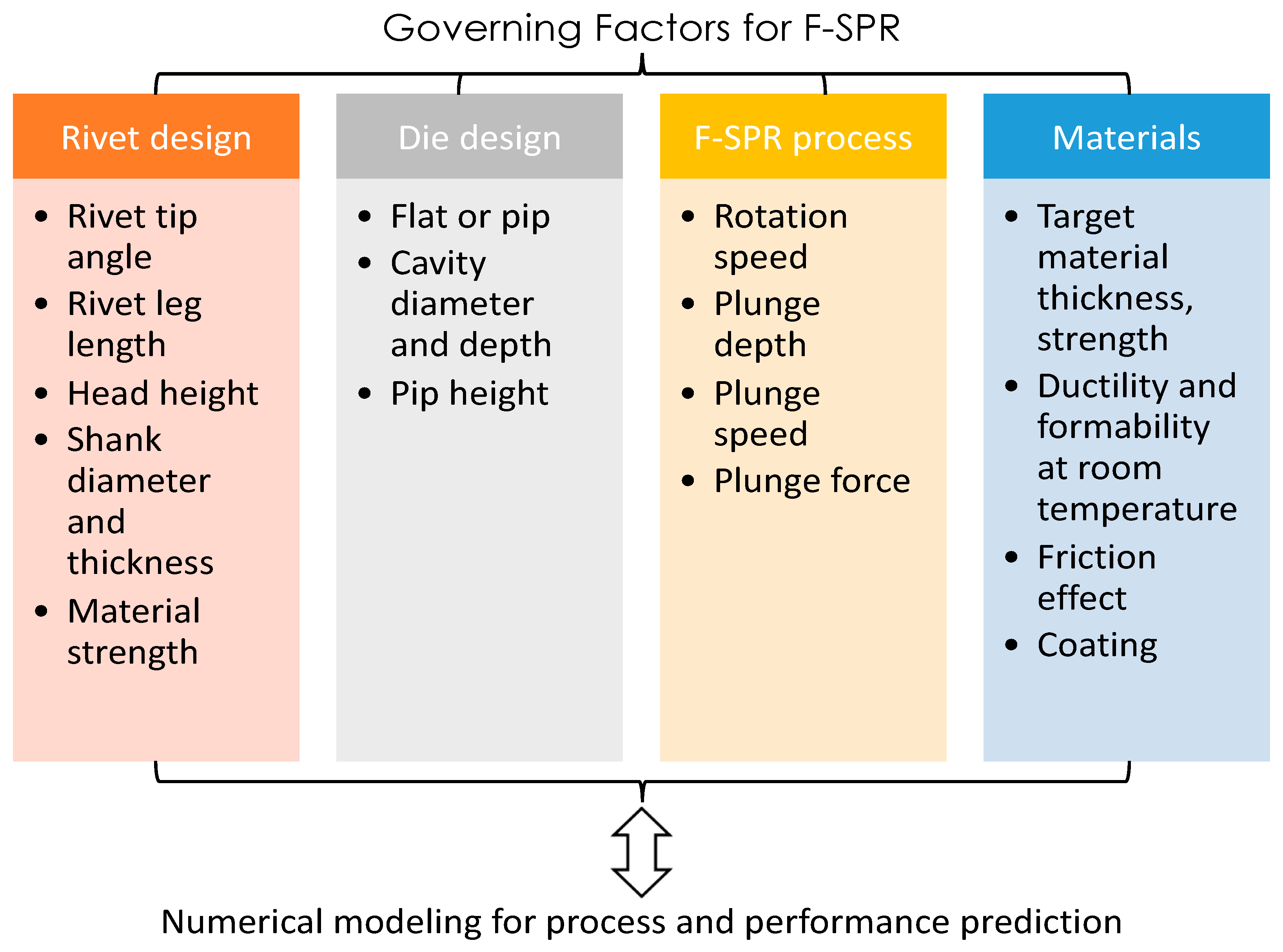
The governing factors in forming a sound F-SPR joint include the geometric design of both the rivet and die, the rivet material, sheet material, and the process parameters (e.g., rotating speed, plunging speed and depth, etc.). The connection and coupling effect of those factors are summarized in Figure 2. As can be seen, the processing condition is closely related to the rivet’s geometry; the plunging depth should be equal to or slightly exceed the leg length of the rivet in order to form a tight contact and interlocking distance. Meanwhile, the plunging depth should not be so large that it prevents the penetration of the rivet through the bottom sheet and reduces the amount of chips on the top sheet surface. The rivet head needs to be designed at a level that can not only sustain the necessary torque and axial downward force for the joining process but also has a minimum height for load-bearing capacity. In addition, the rivet head in the joint will be exposed to corrosive environments during vehicle operations, so the surface area of the rivet head should be minimized. For the die’s geometry, the cavity depth and diameter define the volume of the extruded material of both the rivet leg and the target sheet. Thus, the leg length of the rivet should fit the thickness of the stacked sheets and the cavity depth.
On the material property side, the strength of the rivet and sheet will depend on the temperature and microstructure, which are directly related to heat generation and the strain rate during the F-SPR process. The higher the rotating speed and plunging speed are, the greater the heat generation and strain rate are. In addition, the maximum strain caused by the joining process will not only assist the rivet in piercing the sheet material but also challenge the ductility of the sheet material on the bottom side. Therefore, the die cavity needs to be reasonably designed to enable rivet flaring, and the plunge depth should be precisely controlled to avoid fracturing the bottom sheet. To achieve the above goals, a large number of experiment trials must be conducted, which is neither efficient nor effective in revealing the critical mechanism during the joining process. In the present study, numerical modeling is predominately employed to perform this work, with experimental validation carried out subsequently to save both time and cost.

2.1. Description of Numerical Modeling

The numerical model of friction-based self-piercing riveting is established based on the Dassault-Abaqus 2021® commercial software. The coupled Eulerian–Lagrangian (CEL) approach was employed to simulate the transient temperature, plastic flow, and rivet penetration during F-SPR. The geometry of the rivet is shown in the previous work on Mg-CFRP F-SPR joints [
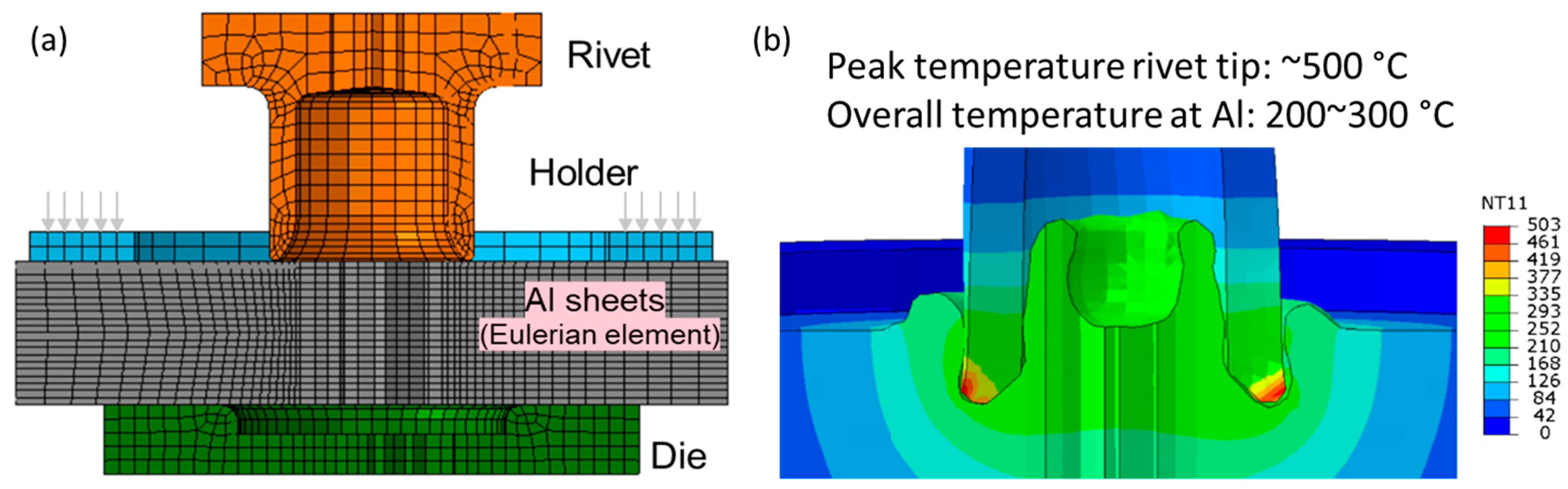
32], and it will be described in the experimental section as well. The thickness of the Al sheets is 2.5 mm, and a flat die with a cavity depth of 1.5 mm was employed. As shown in Figure 3a, the rivet, holder, and die are modeled with Lagrangian elements, which describe the deformation behavior of the material captured by the initial configuration. On the other hand, the Al alloy sheets were modeled with Eulerian elements, through which the material can flow in and out of the fixed mesh. The hexahedral elements (six faces, eight nodes) were adopted for the CEL model; the type is coupled with the thermomechanical element EC3D8T. The ductile fracture model (described in the Abaqus manual) was used to predict the onset of damage by assuming that the equivalent plastic strain at the onset of damage is a function of stress triaxiality and strain rate. In the present study, the fracture strain is assumed to be the elongation of material at a specific temperature (see Table 1), and the strain rate effect is ignored. After damage initiation, the material stiffness starts to degrade gradually before reaching the maximum effective strain. The element stiffness is reduced to a very small fraction (1%) of the original value to enable material separation. The temperature-dependent material properties of the Al and the steel rivet are summarized in Table 1 based on available data from the open literature [33,34,35,36,37]. The yield strength refers to the strength at 0.2% of strain, and the hardening behavior was modeled as linear hardening. In this study, the friction coefficient is 0.4 throughout the analysis. Given the small mesh size used to fit the curvature of the rivet tip, the number of elements in the model is greatly increased, and the time step is reduced to nearly 1 ns. As a result, a large amount of computational cost is required, and the analysis event is limited to sub-seconds. Figure 3b shows the transient temperature during the initial stage of F-SPR. A peak temperature around 500 °C appears in the rivet tip because of high contact stress and frictional heat generation. The overall temperature of the Al sheet ranged from 200 to 300 °C, which is significantly below the melting point of Al material but still high enough to enhance ductility [34,35]. The temperature difference between the rivet and sheet comes from the high thermal conductivity of the Al material relative to that of the steel rivet.
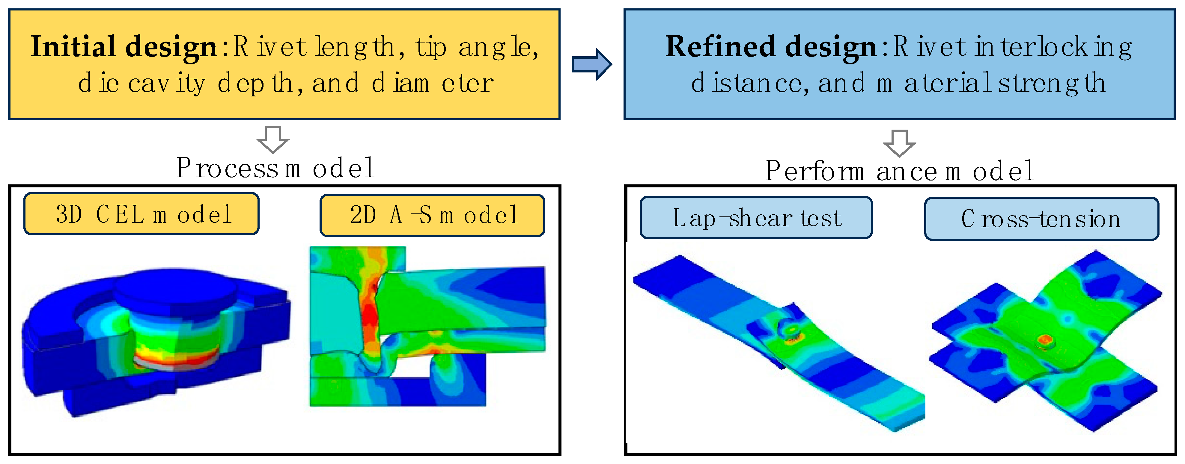
To enable a series of process simulations, it is necessary to derive an approximate model by capturing the essential features, such as heat, friction force, and pressure distribution. A simplified 2D model with equivalent temperature distribution and shear force was proposed to serve this purpose. As shown in Figure 4, the axisymmetric model (A-S model) was employed considering the geometric features of the rivet and the die cavity in F-SPR. Temperature distribution obtained from the 3D model was introduced to the 2D model as a thermal boundary condition. In this study, the temperature of the CEL model at a rivet-plunging depth of 1.2 mm was used as the source of data mapping. During the F-SPR process, this temperature field is kept constant on the nodes of Lagrangian elements, but it changes with the deformation of the rivet and the Al sheets. The heating becomes relatively stable as the rivet penetrates the Al sheet material to a certain depth. The frictional shear force is along the circumferential direction in the actual process, but the application of such forces is limited in the axisymmetric element. Instead, a friction force in the radial direction (horizontal direction in the initial 2D A-S model) was applied to mimic the loading condition necessary for material yielding. In addition, given the significant material softening caused by heat generation, the penetration process of the top sheet was assumed to have a negligible impact on the mechanical behavior of riveting at the bottom sheet. Thus, the top sheet was prepared in a configuration of full rivet penetration to avoid numerical instabilities due to the extreme squeezing and subsequent deleting of elements in the model. The ALE (Arbitrary Lagrangian–Eulerian) method, with an updating frequency of 6–10 time increments, was used to modify the mesh for significant strain and large deformations.
To evaluate the geometrical factor of joint strength, a performance model is also necessary to further refine the design parameters and minimize the design variability as much as possible. In this study, the standard lap–shear test configuration and the cross-tension test for Al-Al rivet joints were numerically investigated. The element type was C3D8R in the performance model, which is a mechanical element of continuum three-dimensional eight-node reduced integration. In the physical experiments, lap–shear tensile testing was conducted on F-SPR specimens using an MTS Systems tensile machine with a constant crosshead speed of 10 mm·min−1. Two shim plates were placed under the workpieces in the lap–shear test to minimize the bending effect. For the lap–shear test coupon, the length and width of the Al sheet were 120 mm and 40 mm, respectively, with a 20 mm overlap. For the cross-tension test coupon, the length and width of the Al sheet were 150 mm and 50 mm, respectively. An overview of the modeling part in the present study is shown in Figure 4.

2.2. Experiment Setup

A benchtop friction bit-joining machine manufactured by Megastir was modified for the experimental study of F-SPR. The joining setup for the lap–shear joint configuration of AA7055 is shown in Figure 5a. Based on the authors’ previous work, the hollow-shaped rivet has a shank diameter of 6.8 mm and a wall thickness of 0.94 mm, as presented in Figure 5b. The rivet head is in a hexagonal shape with a height of 2.54 mm to ensure tight contact between the rivet and the driver tool. A magnetic pin was installed inside the driver to hold the steel rivet before joining. The outer fillet of the rivet head is 0.5 mm, and that of the rivet tip is 0.2 mm. The length of the rivet is 6 mm to cover the total thickness of the two sheets (2.5 mm for each sheet) and the major part of the die cavity depth (1.5 mm). The rivet material is 1018 carbon steel, which has a carbon content of around 0.18%. The yield strength is about 455 MPa at room temperature. Relevant heat treatments, such as oil quench, can enhance the yield strength up to 700 MPa [38]. A schematic of the die’s geometry is plotted in Figure 5c. The inner diameter of the die cavity is 8.2 mm, and the outer diameter is 10.8 mm. The pre-tightening load of the die is determined by a fixed torque in a calibrated wrench. Small round bars inserted into several pre-drilled holes around the test pieces are used to limit the rotational movement of the sheets during F-SPR. After the preliminary experiment, the plunging speed is determined as 2.86 mm/s, and the plunge depth is 6.045 mm. The rotating speed of the driver tool is 3000 rpm.

2.3. Specimen Characterizations

To characterize the microstructure of the joints, metallurgical specimens from the joints were prepared using a standard mechanical polishing method. Grit 320, 600, 800, and 1200 SiC sandpapers were used for grinding; 3 µm and 1 µm diamond suspensions, 0.25 µm and 0.05 µm alumina suspensions, and 0.02 µm colloidal silica were used for polishing. After polishing, the specimens were etched with Keller’s etchant for optical observations with a Zeiss AXIO optical microscope. Vickers hardness mapping measurements were conducted on the as-polished specimens with a load of 100 g, a dwell time of 10 s, and an indent space of 200 µm. Hardness contour maps were plotted from the hardness mapping data.

3. Geometry Design by Numerical Modeling

3.1. Rivet Tip Angle and Die Cavity Depth

The geometry of the rivet and die has a decisive effect on both joint formation and performance, which is particularly true for high-strength material given its strong hardness. More specifically, the rivet tip angle, as well as the die cavity depth, should be designed to match the sheet stack-up and material properties. Meanwhile, mechanical interlocking is also a function of the remaining thickness (t) of any given rivet or tool geometry. The reason for using the remaining thickness as an indicator is that plunging depth can be a variable of sheet thickness and rivet length. Herein, an “old rivet” is defined as a rivet with a tip angle of about 50°, which was used in a previous work on a Mg-CFRP joining case [17]. On the other hand, a rivet with a shaper tip angle (30°) is defined as a “new rivet”. The three different tip angles, 30°, 40°, and 50°, were studied numerically, with the shaper angle (30°) defined as a new rivet. In addition, two cavity depths, 1.0 mm and 1.5 mm, were examined under two different remaining thickness cases, 0.35 mm and 0.5 mm, as defined in Figure 6.
Figure 7 presents distorted mesh for different rivet tip angles and die cavity depths after the rivet plunging depth reaches the same remaining thickness (Tmin). It was found that, under the same remaining thickness, the new rivet provides larger mechanical interlocking than the old rivet. By reducing the remaining thickness from 0.5 mm to 0.35 mm, the interlocking distance can be further increased by 60%. By using a shallower die (cavity depth, dc = 1.0 mm), the interlocking performance becomes slightly better at the cost of greater plunging force. Under the same remaining thickness, a shallower die cavity tends to make the rivet leg thicker because of significant hydrostatic pressure. Table 2 summarizes the predicted interlocking distances with different rivet tip angles and die cavity depths.
Figure 8 further compares the interlocking distance trend with variations in the rivet tip angle and remaining thickness. The case of a smaller remaining thickness, Tmin = 0.35 mm, basically resulted in a doubled interlocking distance compared with the case of Tmin = 0.5 mm, which indicates that the rivet length and plunging depth can be refined to achieve the best performance of the designed rivet. On the other hand, a sharper rivet angle leads to increased mechanical interlocking with a shallower die (cavity, 1.0 mm). It can also be concluded that the rivet-interlocking behavior is less sensitive to rivet tip angle with a die cavity depth of 1.5 mm.

3.2. Effect of Rivet Shank Diameter and Material Strength

The load-carrying capacity depends not only on the interlocking distance but also on the rivet cross-sectional area, which is a function of the rivet shank diameter and wall thickness. In addition, the rivet material strength plays a critical role in governing the joint strength. For a given interlocking distance, a performance model can be employed to conduct a sensitivity study on the rivet shank diameter, as well as its material strength. Herein, two rivet diameters were numerically studied; the diameter of the first rivet is 5.2 mm (typical rivet shank diameter for SPR) and that of the second rivet is 7.8 mm, while the wall thickness is kept the same for both. The tensile strengths (Rm) of the rivet are 560 MPa and 780 MPa, corresponding to the as-received case and the heat-treated case. Only half the model was considered given the symmetry in evaluating the joint shear strength. Currently, no residual stresses are included in the performance model for simplicity. Figure 9 and Figure 10 are the computational results of the rivet failure mode and joint load–displacement curves under different material strengths and rivet diameters. In Figure 9, the interlock distances are assumed to be 0.6 mm in order to be consistent for comparison.
When the rivet shank diameter is 5.2 mm, the peak load is below 6 kN because a small effective joint area sustains the shear load. For the regular rivet without heat treatment (Rm = 560 MPa), the rivet fractures at the cross-section near the joint interface between the Al sheets, and the peak tensile load is 4.2 kN compared with 5.3 kN in the case of the heat-treated rivet (Rm = 760 MPa). When the rivet shank diameter is increased to 7.8 mm, as shown in Figure 10, the peak load of the rivet joint is above 10 kN, which is basically doubled from the previous cases. For the case with the heat-treated rivet especially, the shear load-carrying capacity reached 12 kN, and the F-SPR joint exhibited a button-pull-out failure mode rather than a rivet failure. It is interesting to note that the joint without an interlocking distance (Int = 0 mm) also delivered a shear load of just 2 kN less than the Int = 0.6 mm case; this is because the shear load direction is normal to the rivet axial direction, and the effective load-bearing area is more than 45 mm2.
Based on the above analysis, the rivet was designed with a larger diameter of 7.2 mm, a tip angle of 30°, and a die cavity depth of 1.2 mm. After machining the rivets, the material was heat-treated with tempering at 900 °C for 2 h followed by oil quenching. Such a joint modification is defined as the first iteration of the design, and an optical observation of the F-SPR joint is shown in Figure 11. The overall rivet flaring and Al sheet bottom finishing are satisfactory, although there is a slight lack of material fill inside the rivet, which indicates the plunging depth can be further increased. This is also evidenced by the large remaining thickness, which is about 0.75 mm. On the other hand, the rivet head seems to have redundant material, which will increase the weight of the F-SPR joint. The new rivet has a sharp tip for penetrating material, and thus, mechanical interlocking is greatly increased, which is promising for achieving higher lap–shear strength and cross-tension capacity loads. The experimental results are discussed in Section 4.
Generally speaking, the residual stresses generated in the F-SPR process should be considered in the performance model to predict more accurate joint strength for the specimen. In the present study, the residual stresses were not included in the performance model; all case studies were based on initial stress-free conditions, though the absolute values of the predicted joint strength may be different from the actual measurement. The prediction under different rivet geometries and material strengths remains valid for capturing the trend of joint strength. Complete 3D process modeling will be needed to predict the residual stress and map the results to the performance model.

3.3. Rivet Head Height Reduction

The rivet head represents another geometric factor that can influence the mass added to the joint and the load transferred from the rivet driver to the rivet leg. The original design of the rivet features a height of 2.54 mm to ensure torque delivery and driver–rivet alignment. In the new rivet design, the internal cavity shape in the rivet head, as can be seen in Figure 11, is first removed because of the remaining cavity after joining. Then, a static load analysis of the rivet is performed to evaluate the plastic strain produced under the combined load. In the numerical model, the displacement at the bottom region of the rivet leg is fixed in all three directions. An axial force of 10 kN is applied to the top surface of the rivet to simulate the peak downward force measured during the actual joining process. Aside from the load in the vertical direction, a distributed shear load is defined on the side surfaces of the rivet head, which is in a hexagonal prism shape. The calculated torque through the center of the rivet is 5 N·m, which is a typically measured value in machines in Al-Al friction stir self-piercing riveting. Based on the previous modeling results, a rivet shank diameter of 7.2 mm is employed in modeling, and the material strength of the mild steel is defined as 760 MPa under heat treatment conditions. As shown in Figure 12, the combined axial load and torque induce no significant plastic strain on the rivet head, and most of the plastic strain is focused on the rivet leg. The peak stress and strain remain low in the head region even though the head thickness is reduced to 1.0 mm. The shear stress can be high in the rivet head under the torque delivered by the rivet driver, and the rivet head can be sheared off in the worst-case scenario.
In addition to the load analysis during processing, the performance of the rivet during service should be investigated because the external load may result in rivet failure if the head is too thin. In order to confirm that the 1.0 mm rivet is strong enough to resist bending and shear, a performance model of cross-tension was developed to examine the stress concentration and failure mode. As shown in Figure 13, the F-SPR joint fails at the bottom Al sheet when solid-state joining is considered. On the other hand, if the joint is mechanically fastened only, the cross-tension joint will fail in rivet pull-out mode. In both cases, the rivet head remains strong enough, as only a small amount of plastic strain (<9%) has occurred at the rivet head. When solid-state joining is assumed at the rivet–Al interface, the joint will achieve a much-improved strength (5.25 kN compared with 3.5 kN) since the bottom Al material has to be fractured before the rivet can be pulled out. Solid-state joining between the rivet head and the top Al sheet will alleviate the stress concentration in the joint, which is helpful for reducing plastic strain in the rivet.

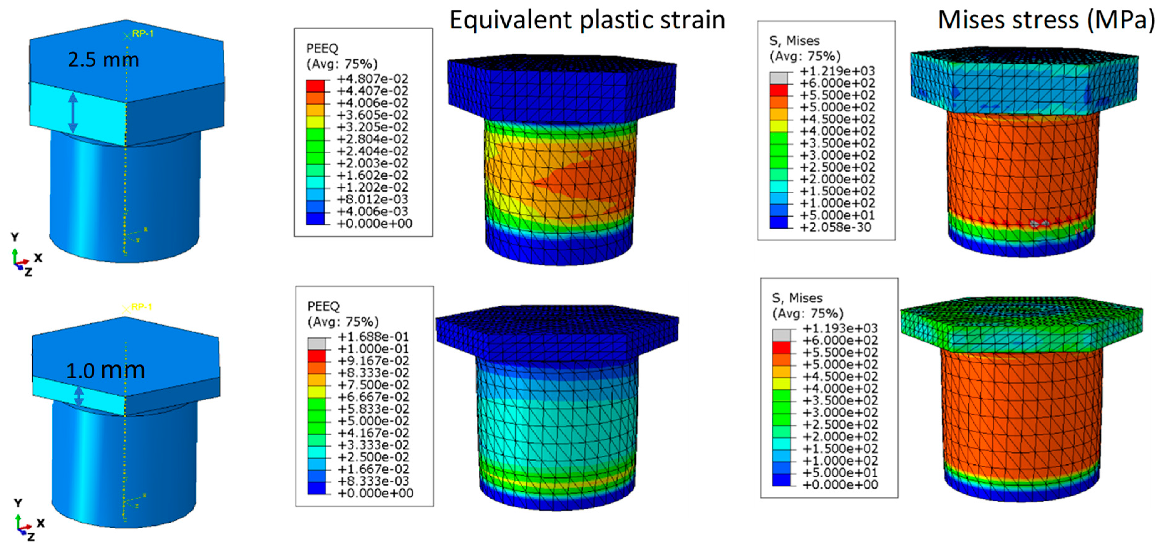
4. Characterizations and Mechanical Joint Performances

Using the above iteration of the design, the final geometry of the rivet is determined for the 2T AA7055 material. The rivet head thickness is finalized as 1 mm, the shank diameter is 7.2 mm, and the wall thickness is 0.94 mm. All rivets are heat-treated with conditions described in Section 3.2. The hardened material will keep the rivet tip as strong as possible when it pierces the high-strength Al material, but it may limit rivet flaring because of its high yield strength. 
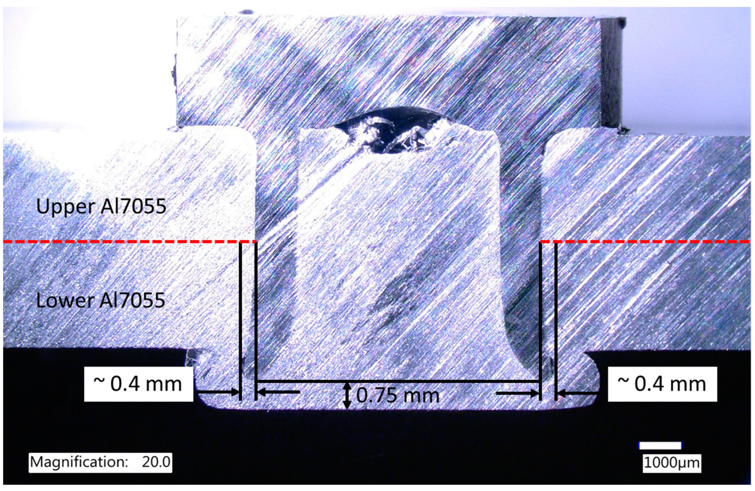
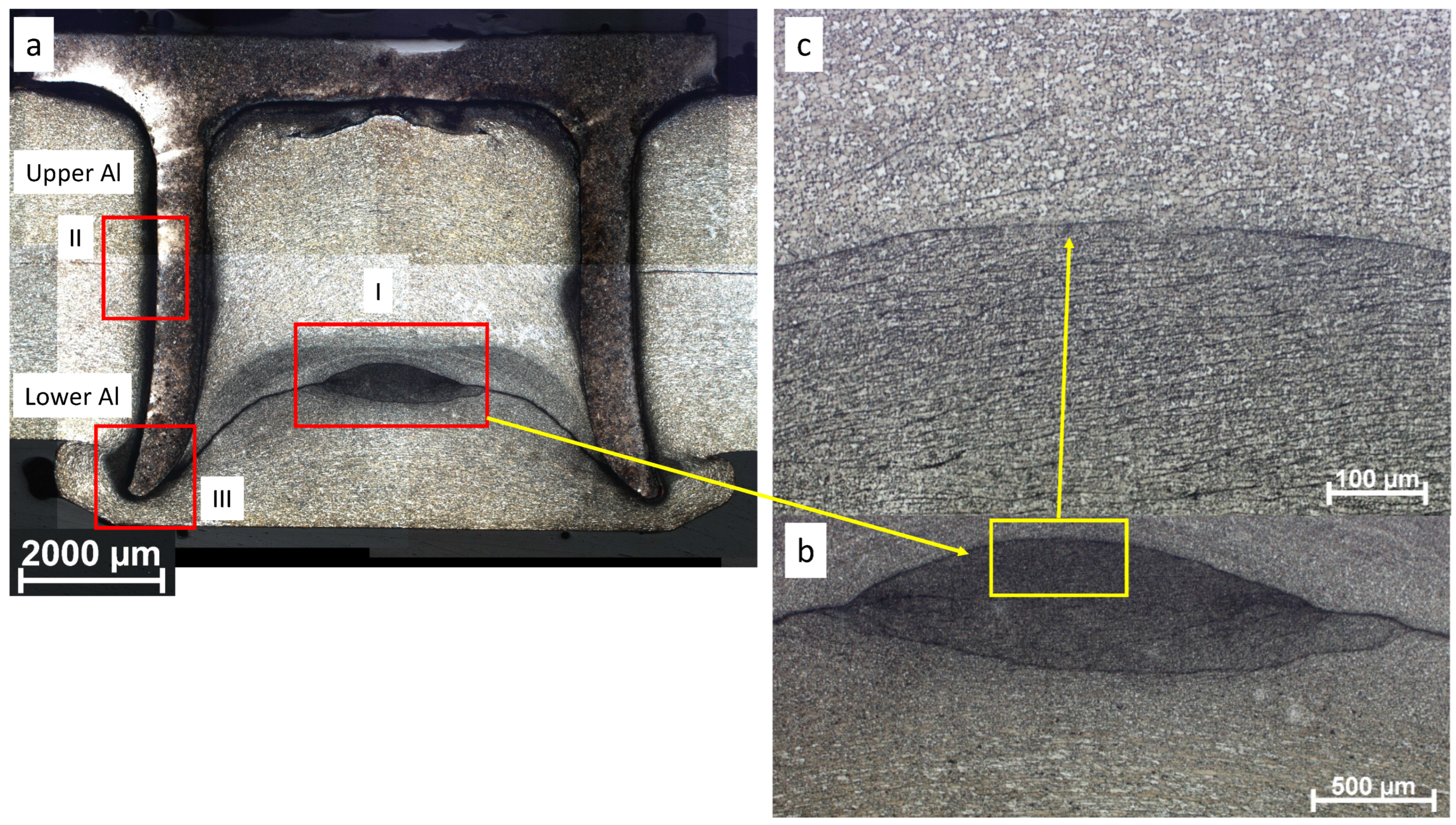
Figure 14 consists of a macrograph of the new F-SPR joint and a magnified optical image of the rivet joint cap. Figure 14a shows a crack-free F-SPR Al-Al joint with mechanical interlocking between the flared rivet leg and the bottom Al sheet. The measured mechanical interlocking distance is around 0.46 mm, which is similar to the predicted value in the numerical model. In addition, it can be observed that the remaining thickness in Al-Al joining is 0.4 mm, reduced from 0.75 mm in the initial case. Figure 14b,c show solid-state joining between the upper and lower Al sheets inside the rivet cap (zone I in Figure 14a). A continuous material flow line between the upper and lower Al sheets is seen because of an interaction with the rivet during the joining process. Also, solid-state joining can be observed because of the combined effects of frictional heat and compressive axial load from the joining process. 
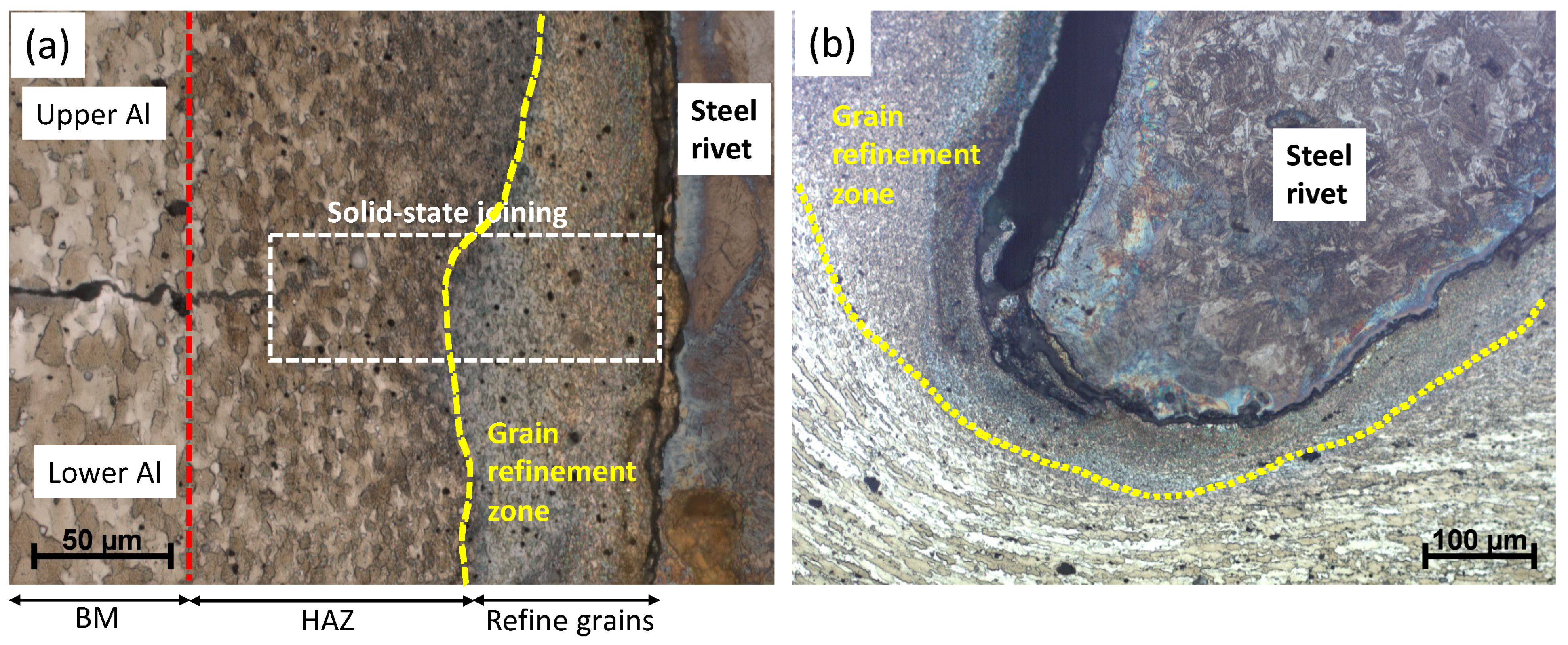
Figure 15 presents magnified optical images of zones II and III from Figure 14a. A magnified optical image of the left side of the joint is presented in Figure 15a. The grain refinement of the Al where it is very close to the steel rivet can be observed because of dynamic recrystallization caused by frictional and severe plastic deformations. Also, approximately 150 μm of solid-state joining area between the upper and lower Al sheets can be found. In addition, three distinctive areas, including the base metal (BM), a heat-affected zone (HAZ), and a grain refinement zone, can be found in the etched sample. Figure 15b presents a magnified optical image of the rivet tip on the left side of the joint marked in zone III in Figure 14a. Again, the grain refinement of the Al material can be observed around the rivet leg where the most intensive frictional and severe plastic deformations occurred. Furthermore, the elongated grain structure can be found because of the rotational motion of the rivet during the joining process. The evolution of the microstructure is further correlated to the microhardness measurement in the section below.
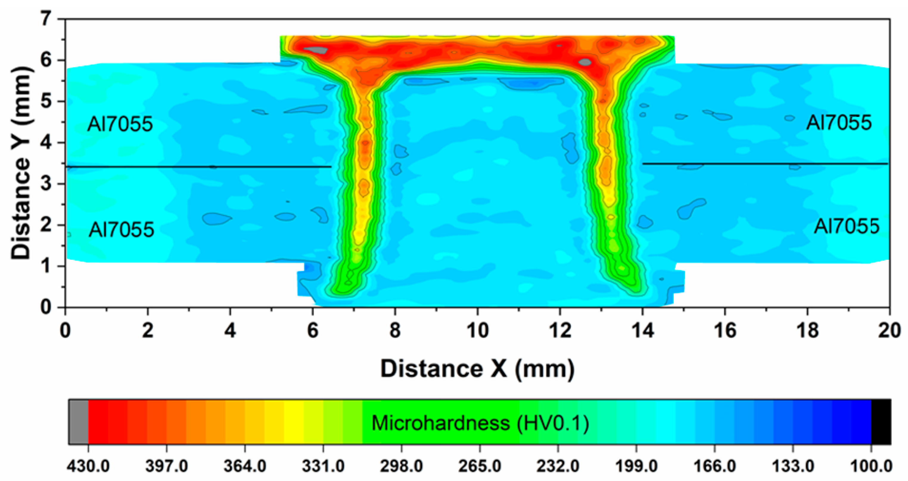
A microhardness map of the cross-sectioned Al-Al F-SPR joint in the new design is plotted in Figure 16. The rivet head (cap) is exposed to fewer heat effects, so it can be used as a reference in as-heat-treated conditions. As a result of tempering and quenching prior to joining, the maximum microhardness of the rivet reached above 400 HV, which is improved from 280 HV in as-received conditions. For the whole rivet, the tip region exhibits the lowest hardness because of large frictional heat generation and material softening. The average microhardness of the Al alloy is about 190 HV. Increased hardness in the region near the rivet–Al interface can be observed, which is evidence of the grain refinement of the Al alloy at a high temperature and a high strain rate. It should also be noted that large amounts of Al outside the rivet cavity (i.e., HAZ) show lower microhardness, which indicates material softening; in particular, the region near the rivet tip area could be a weak point during mechanical tests.
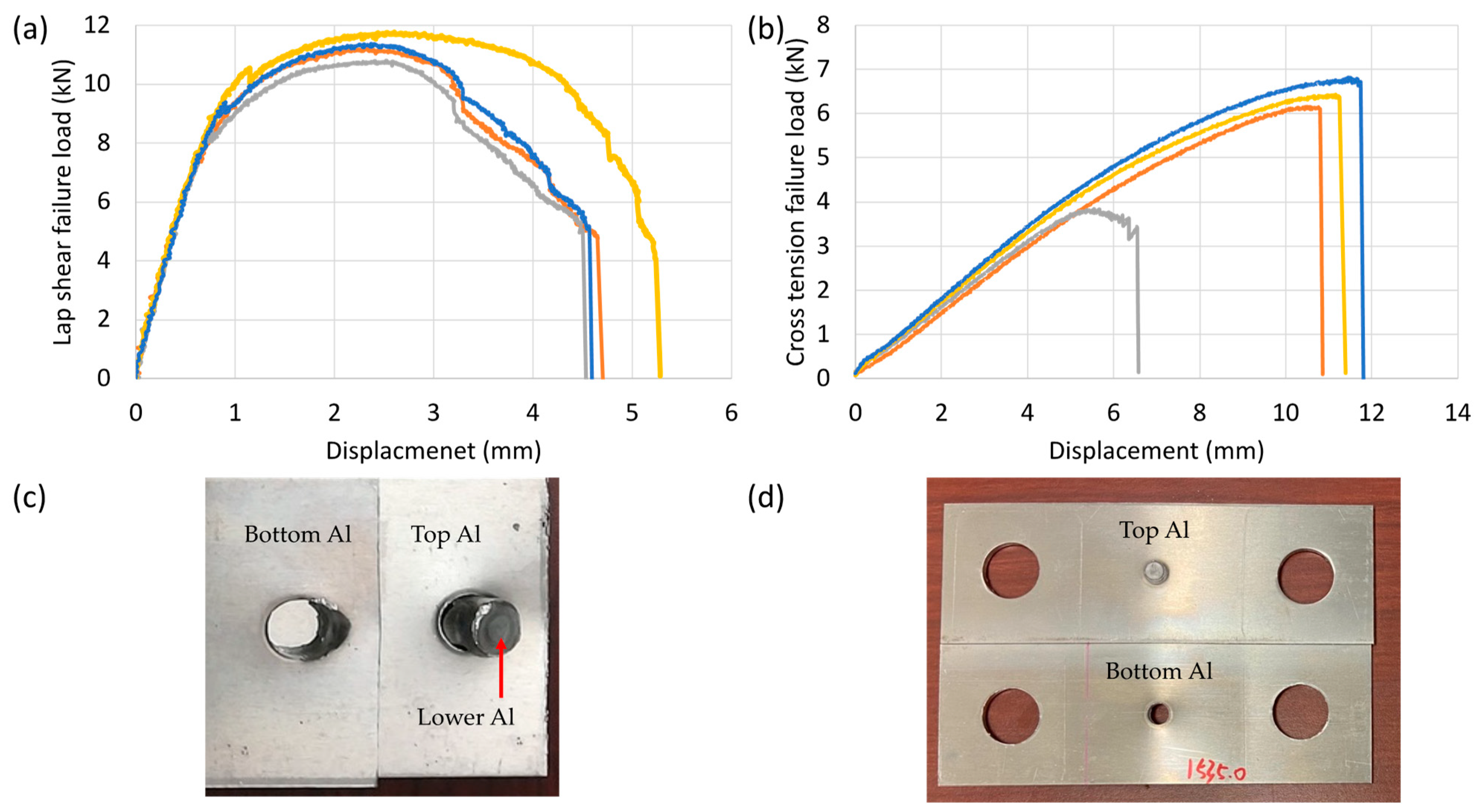
Mechanical performance studies using lap–shear tensile tests and cross-tension tests were carried out on four repeated samples. In Figure 17a, it can be seen that an average peak failure load of 11.3 ± 0.35 kN was achieved. 
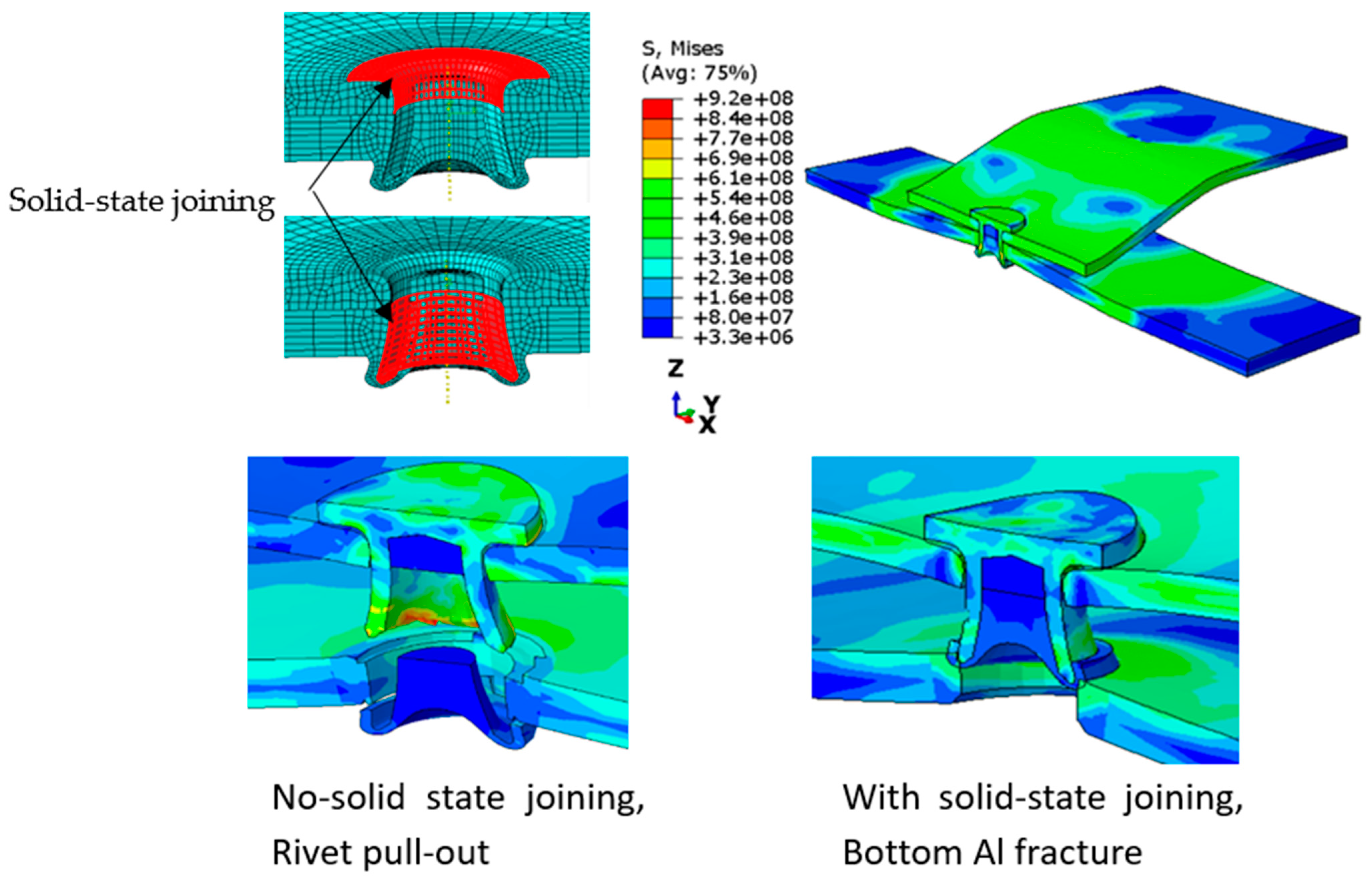
Table 3 summarizes the lap–shear tensile strength of various Al-alloy-to-Al-alloy, casting Al, steel, and Mg alloy joints with different joining techniques (e.g., refill friction stir spot welding (RFSSW), SPR, F-SRP, and FSBR) from the available open literature. While recognizing that a direct comparison of joint strength may not be feasible because of potential variations in material strengths and coupon geometry, the results illustrate the current state of joining technology for readers. In addition, the failure mode of all four coupons was the bottom Al pulling out (Figure 17c) at the joint, indicating good mechanical interlocking and solid-state joining between the Al-Al and Al-steel rivets. This is evidenced by the grain refinement and material flow of Al near the rivet joint, as shown in Figure 14 and Figure 15. Figure 17b shows that the average cross-tension strength was found to be 5.82 ± 1.35 kN, and three out of four samples exhibited bottom Al sheet failure (Figure 17d), which is also attributable to strong mechanical interlocking and solid-state bonding. There is an exception, however, in that one sample was pulled out prematurely (tensile load 3.8 kN), which was probably due to a shorter rivet length, which resulted in small mechanical interlocking. According to the modeling results in Figure 13, another reason for this phenomenon may be insufficient solid-state bonding due to reduced heat generation or excessive surface oxidation. More attention should be paid to quality control in the rivet manufacturing process and Al sheet preparation.

5. Conclusions

A comprehensive study, including modeling and experiments, was conducted to join high-strength AA7055 sheets using novel, friction-based, self-piercing rivets. The following conclusions can be drawn:
(1)
Rivet tip angle and remaining thickness are two important factors determining the mechanical interlocking distance. With smaller tip angles and remaining thicknesses, the interlocking distance increases significantly. The die cavity depth shows larger influences at smaller remaining thicknesses.
(2)
The material strength of the rivet (i.e., the tensile strength) is critical to the lap–shear strength of F-SPR joints. Rivet fractures will occur in as-received rivets with relatively weak strength and small rivet shank diameters. By increasing the rivet shank diameter and employing heat treatments, the lap–shear strength of the joint can be greatly enhanced.
(3)
The rivet head height can be reduced to 1 mm according to a static analysis of combined axial downward force and torque. A numerical cross-tension test confirmed that the failure mode will be rivet pull-out or a bottom-Al material fracture rather than damage to the rivet head.
(4)
Owing to the mechanical interlocking and solid-state joining between the top and bottom Al sheets, the refined design of the rivet joint is capable of sustaining a tensile shear load of up to 11.3 kN and a cross-tension load of 5.8 kN, both showing bottom-Al fracture and then rivet pull-out.
(5)
This model-guided design saves considerable experimental trial and development time, resulting in improved joint strength and reduced weight. The process model and performance model together can refine the joint geometry and process parameters for high-quality friction stir self-piercing riveting processes.

Author Contributions

Conceptualization, H.H. and Y.C.L.; methodology, H.H. and Y.C.L.; investigation, H.H., Y.W., Z.F. and Y.L.; writing—original draft preparation, H.H., Y.W. and Y.C.L.; writing—review and editing H.H., Y.C.L. and Y.W.; visualization, H.H., Y.L. and Y.W.; supervision, Z.F.; project administration, Y.C.L. and Z.F.; funding acquisition, Z.F. All authors have read and agreed to the published version of the manuscript.

Funding

U.S. Department of Energy Office of Energy Efficiency and Renewable Energy, Vehicle Technology Office under contract DE-AC05-00OR22725.

Data Availability Statement

Data sharing is not applicable to this article.

Acknowledgments

The authors thank Russell Long (retired) and Santosh Prasad at Arconics for providing materials and Eric Boettcher at Honda R&D Americas, LLC., for technical input.

Conflicts of Interest

The authors declare no conflict of interest.

Notice of Copyright:

This manuscript was authored by UT-Battelle, LLC, under contract DE-AC05-00OR22725 with the US Department of Energy (DOE). The US government retains and the publisher, by accepting the article for publication, acknowledges that the US government retains a nonexclusive, paid-up, irrevocable, worldwide license to publish or reproduce the published form of this manuscript, or allow others to do so, for US government purposes. The DOE will provide public access to the results of this federally sponsored research in accordance with the DOE Public Access Plan (http://energy.gov/downloads/doe-public-access-plan (accessed on 20 November 2023)).

References

  1. Kleinbaum, S.; Jiang, C.; Logan, S. Enabling sustainable transportation through joining of dissimilar lightweight materials. MRS Bull. 2019, 44, 608–612. [Google Scholar] [CrossRef]
  2. Huo, W.; Hou, L.; Lang, Y.; Cui, H.; Zhuang, L.; Zhang, J. Improved thermo-mechanical processing for effective grain refinement of high-strength aa 7050 al alloy. Mater. Sci. Eng. A 2015, 626, 86–93. [Google Scholar] [CrossRef]
  3. Patel, V.; Bhole, S.; Chen, D. Influence of ultrasonic spot welding on microstructure in a magnesium alloy. Scr. Mater. 2011, 65, 911–914. [Google Scholar] [CrossRef]
  4. Santella, M.; Franklin, T.J.; Pan, J.; Pan, T.-Y.; Brown, E. Ultrasonic spot welding of AZ31B to galvanized mild steel. SAE Int. J. Mater. Manuf. 2010, 3, 652–657. [Google Scholar] [CrossRef]
  5. Mishra, R.S.; Ma, Z.Y. Friction stir welding and processing. Mater. Sci. Eng. R Rep. 2005, 50, 1–78. [Google Scholar] [CrossRef]
  6. Lim, Y.C.; Squires, L.; Pan, T.-Y.; Miles, M.; Song, G.-L.; Wang, Y.; Feng, Z. Study of mechanical joint strength of aluminum alloy 7075-T6 and dual phase steel 980 welded by friction bit joining and weld-bonding under corrosion medium. Mater. Des. 2015, 69, 37–43. [Google Scholar] [CrossRef]
  7. Jiang, B.; Chen, Q.; Yang, J. Advances in joining technology of carbon fiber-reinforced thermoplastic composite materials and aluminum alloys. Int. J. Adv. Manuf. Technol. 2020, 110, 2631–2649. [Google Scholar] [CrossRef]
  8. Martinsen, K.; Hu, S.J.; Carlson, B.E. Joining of dissimilar materials. CIRP Ann. 2015, 64, 679–699. [Google Scholar] [CrossRef]
  9. Khan, H.A.; Li, J.; Shao, C. Analyses of friction stir riveting processes: A review. J. Manuf. Sci. Eng. 2017, 139, 090801. [Google Scholar] [CrossRef]
  10. Gao, D.; Ersoy, U.; Stevenson, R.; Wang, P.-C. A new one-sided joining process for aluminum alloys: Friction stir blind riveting. J. Manuf. Sci. Eng. 2009, 131, 061002. [Google Scholar] [CrossRef]
  11. Min, J.; Li, J.; Li, Y.; Carlson, B.E.; Lin, J.; Wang, W.-M. Friction stir blind riveting for aluminum alloy sheets. J. Mater. Process. Technol. 2015, 215, 20–29. [Google Scholar] [CrossRef]
  12. Li, Y.; Wei, Z.; Wang, Z.; Li, Y. Friction self-piercing riveting of aluminum alloy AA6061-T6 to magnesium alloy AZ31B. J. Manuf. Sci. Eng. 2013, 135, 061007. [Google Scholar] [CrossRef]
  13. Porcaro, R.; Hanssen, A.; Langseth, M.; Aalberg, A. Self-piercing riveting process: An experimental and numerical investigation. J. Mater. Process. Technol. 2006, 171, 10–20. [Google Scholar] [CrossRef]
  14. Liu, X.; Lim, Y.C.; Li, Y.; Tang, W.; Ma, Y.; Feng, Z.; Ni, J. Effects of process parameters on friction self-piercing riveting of dissimilar materials. J. Mater. Process. Technol. 2016, 237, 19–30. [Google Scholar] [CrossRef]
  15. Ma, Y.; Shan, H.; Niu, S.; Li, Y.; Lin, Z.; Ma, N. A comparative study of friction self-piercing riveting and self-piercing riveting of aluminum alloy AA5182-O. Engineering 2020, 7, 1741–1750. [Google Scholar] [CrossRef]
  16. Ma, Y.; Li, Y.; Lin, Z. Joint formation and mechanical performance of friction self-piercing riveted aluminum alloy AA7075-T6 joints. J. Manuf. Sci. Eng. 2019, 141, 041005. [Google Scholar] [CrossRef]
  17. Lim, Y.C.; Jun, J.; Leonard, D.N.; Li, Y.; Chen, J.; Brady, M.P.; Feng, Z. Study of galvanic corrosion and mechanical joint properties of AZ31B and carbon-fiber–reinforced polymer joined by friction self-piercing riveting. J. Magnes. Alloy 2021, 10, 400–410. [Google Scholar] [CrossRef]
  18. Hovanski, Y.; Upadyay, P.; Kleinbaum, S.; Carlson, B.; Boettcher, E.; Ruokolainen, R. Enabling dissimilar material joining using friction stir scribe technology. JOM 2017, 69, 1060–1064. [Google Scholar] [CrossRef]
  19. Daehn, G.S.; Daehn, K.E.; Kuttner, O. Environmentally Responsible Lightweight Passenger Vehicle Design and Manufacturing. Automot. Innov. 2023, 6, 300–310. [Google Scholar] [CrossRef]
  20. Xu, Z.; Li, Z.; Ji, S.; Zhang, L. Refill friction stir spot welding of 5083-O aluminum alloy. J. Mater. Sci. Technol. 2018, 34, 878–885. [Google Scholar] [CrossRef]
  21. Huang, L.; Lasecki, J.V.; Guo, H.; Su, X. Finite element modeling of dissimilar metal self-piercing riveting process. SAE Int. J. Mater. Manuf. 2014, 7, 698–705. [Google Scholar] [CrossRef]
  22. Rusia, A.; Weihe, S. Development of an end-to-end simulation process chain for prediction of self-piercing riveting joint geometry and strength. J. Manuf. Process. 2020, 57, 519–532. [Google Scholar] [CrossRef]
  23. Casalino, G.; Rotondo, A.; Ludovico, A. On the numerical modelling of the multiphysics self piercing riveting process based on the finite element technique. Adv. Eng. Softw. 2008, 39, 787–795. [Google Scholar] [CrossRef]
  24. Deng, J.-H.; Lyu, F.; Chen, R.-M.; Fan, Z.-S. Influence of die geometry on self-piercing riveting of aluminum alloy AA6061-T6 to mild steel SPFC340 sheets. Adv. Manuf. 2019, 7, 209–220. [Google Scholar] [CrossRef]
  25. Karathanasopoulos, N.; Pandya, K.S.; Mohr, D. An experimental and numerical investigation of the role of rivet and die design on the self-piercing riveting joint characteristics of aluminum and steel sheets. J. Manuf. Process. 2021, 69, 290–302. [Google Scholar] [CrossRef]
  26. Bouchard, P.; Laurent, T.; Tollier, L. Numerical modeling of self-pierce riveting—From riveting process modeling down to structural analysis. J. Mater. Process. Technol. 2008, 202, 290–300. [Google Scholar] [CrossRef]
  27. Ma, Y.; Li, Y.; Hu, W.; Lou, M.; Lin, Z. Modeling of friction self-piercing riveting of aluminum to magnesium. J. Manuf. Sci. Eng. 2016, 138, 061007. [Google Scholar] [CrossRef]
  28. Geng, P.; Ma, Y.; Ma, N.; Ma, H.; Aoki, Y.; Liu, H.; Fujii, H.; Chen, C. Effects of rotation tool-induced heat and material flow behaviour on friction stir lapped Al/steel joint formation and resultant microstructure. Int. J. Mach. Tools Manuf. 2022, 174, 103858. [Google Scholar] [CrossRef]
  29. Shokri, V.; Sadeghi, A.; Sadeghi, M. Thermomechanical modeling of friction stir welding in a Cu-DSS dissimilar joint. J. Manuf. Process. 2018, 31, 46–55. [Google Scholar] [CrossRef]
  30. Long, R.S.; Boettcher, E.; Crawford, D. Current and future uses of aluminum in the automotive industry. JOM 2017, 69, 2635–2639. [Google Scholar] [CrossRef]
  31. Upadhyay, P.; Das, H.; Frank, M.; Balusu, K.; Smith, C.; Choi, W.; Soulami, A.; Lim, Y.C.; Feng, Z.; Huang, H.; et al. Solid-State Joining of Multi-Material Autobody Parts toward Industry Readiness; DOE Vehicle Technology Offices Annual Merit Review: Washington, DC, USA, 2022.
  32. Lim, Y.C.; Chen, J.; Jun, J.; Leonard, D.N.; Brady, M.P.; Warren, C.D.; Feng, Z. Mechanical and Corrosion Assessment of Friction Self-Piercing Rivet Joint of Carbon Fiber-Reinforced Polymer and Magnesium Alloy AZ31B. J. Manuf. Sci. Eng. 2020, 143, 031006. [Google Scholar] [CrossRef]
  33. Ma, F.J.; Fu, D.Y.; Liu, Y.; Yang, D.P.; Zhang, S.F.; Sha, Z.H. The Numerical Simulation of Temperature Field in Friction Stir Welding of 7075 Aluminium Alloy. In Proceedings of the 2019 5th International Conference on Mechanical and Aeronautical Engineering (ICMAE 2019), Sanya, China, 12–15 December 2019; Volume 751, p. 012081. [Google Scholar] [CrossRef]
  34. Shao, Y.; Liu, Q.; Yan, L.; Shi, J.; Guo, P.; Chen, S.A. New Constitutive Model for 7055 Aluminum Alloy. J. Mater. Eng. Perform. 2022, 31, 8183–8198. [Google Scholar] [CrossRef]
  35. Zhang, P.; Li, Y.; Liu, Y.; Zhang, Y.; Liu, J. Analysis of the microhardness, mechanical properties and electrical conductivity of 7055 aluminum alloy. Vacuum 2020, 171, 109005. [Google Scholar] [CrossRef]
  36. Clain, F.M.; Teixeira, P.R.d.F.; de Araújo, D.B. Two heat source models to simulate welding processes with magnetic deflection. Soldag. Inspeção 2017, 22, 99–113. [Google Scholar] [CrossRef]
  37. Badaruddin, M.; Wardono, H.; Zulhanif Supriadi, H.; Salimor, M. Experimental investigation of mechanical proper-ties of cold-drawn AISI 1018 steel at high-temperature steady-state conditions. J. Mater. Res. Technol. 2020, 9, 1893–1904. [Google Scholar] [CrossRef]
  38. Mosa, S.J. Effect of different quenching media on mechanical properties of AISI 1018 low carbon steel. J. Mech. Eng. Res. Dev. (JMERD) 2019, 42, 81–83. [Google Scholar]
Figure 1. (a) Illustration of Al-intensive BIW autobody structure design; (b) examples of two sectional views of the complex shape of the BIW Al structure with an FSLW location; (c) general clamping strategies for flat bead on plate FSLW; (d) new approach utilizing F-SPR tack spot joints made of Al alloys to reduce complex clamping design and excessive clamping force prior to FSLW [31].
Jmmp 07 00216 g001
Figure 2. Design–process–property relationship and governing factors of joint strength.
Jmmp 07 00216 g002
Figure 3. Finite-element model of F-SPR process with coupled Eulerian and Lagrangian method: (a) mesh division and Eulerian domain; (b) predicted temperature distribution after 1.5 mm plunge depth.
Jmmp 07 00216 g003
Figure 4. Illustration of modeling work for refining rivet and tool designs by using process and performance models.
Jmmp 07 00216 g004
Figure 5. F-SPR experiment setup and initial design of rivet and die: (a) image of Al-Al lap joint preparation; (b,c) schematic drawings of rivet and die with dimensions. Unit is mm.
Jmmp 07 00216 g005
Figure 6. Case study of rivet angle, die cavity depth, and definition of variables (Int and Tmin) at the joint for quality indication.
Jmmp 07 00216 g006
Figure 7. Influence of rivet tip angle and die cavity on rivet-flaring performance.
Jmmp 07 00216 g007
Figure 8. Summary of interlocking distance at different die cavity depths and rivet tip angles: (a) die cavity depth, dc = 1.5 mm; (b) die cavity depth, dc = 1.0 mm.
Jmmp 07 00216 g008
Figure 9. Performance modeling of rivet joint with a shank diameter of 5.2 mm: (a) Mises stress distribution and joint distortion at a peak load of about 5.3 kN (Ts = 560 MPa); (b) load–displacement curve for different rivet material strengths.
Jmmp 07 00216 g009
Figure 10. Performance modeling of rivet joint with a shank diameter of 7.8 mm: (a) Mises stress distribution and joint distortion at a peak load of about 12 kN (Rm = 760 MPa); (b) load–displacement curve for different rivet interlock sizes.
Jmmp 07 00216 g010
Figure 11. Rivet shape and interlocking performance after the first iteration of the design.
Jmmp 07 00216 g011
Figure 12. Static analysis of the rivet under an axial compression load of 10 kN and a torque 5 of N·m.
Jmmp 07 00216 g012
Figure 13. Cross-tension performance modeling for 1.0 mm rivet head. When no solid-state joining is considered, rivet pull-out failure is predicted from cross-tension testing. Bottom Al fracture is predicted when solid-state joining between the rivet and surrounding Al materials is considered.
Jmmp 07 00216 g013
Figure 14. (a) Optical macrograph showing cross-sections of F-SPR AA7055 joint: (a) macrograph of F-SPR Al7055-Al7055 joint after joining; (b,c) magnified optical images showing solid-state joining between upper and lower Al sheets in the rivet cap area (zone I in (a)).
Jmmp 07 00216 g014
Figure 15. (a) Magnified optical image of the joint interface on the left side showing solid-state joining between upper and lower Al sheets and grain refinement area marked in zone II in Figure 14a; (b) magnified optical image of the rivet tip region on the left side of the joint showing refined grain.
Jmmp 07 00216 g015
Figure 16. Vickers microhardness mapping of the refined F-SPR joint.
Jmmp 07 00216 g016
Figure 17. Mechanical joint performance studies of Al-Al F-SPR joints: (a) load–displacement curve of standard lap–shear tensile test; (b) load–displacement curve of cross-tension test; (c) fractography of lap–shear tensile-tested coupons, showing fracture of bottom Al at the joint; (d) fractography of cross-tension-tested Al coupons, showing fracture of bottom Al at the joint.
Jmmp 07 00216 g017
Table 1. Temperature-dependent material properties of Al and steel used for F-SPR simulation.
AA7055 [33,34,35] AISI 1018 [36,37]
Temperature T (°C)2020040020400750
Conductivity, k (W/m/K)16714212853.542.926.7
Heat capacity, c (J/kg/K)8359741128486480695
Yield Strength, Rp0.2 (MPa)5353107545546182
Tensile strength, Rm (MPa)5823369056057593
Hardening rate, H (MPa)522272150502516291100
Elongation, ε (%)92280242548
Table 2. Summary of influence of rivet tip angle and die cavity depth on interlocking distance.
Remaining ThicknessOld Rivet
(dc = 1.5 mm)
New Rivet
(dc = 1.5 mm)
New Rivet
(dc = 1.0 mm)
Tmin = 0.50 mmInt = 0.12 mmInt = 0.31 mmInt = 0.33 mm
Tmin = 0.35 mmInt = 0.20 mmInt = 0.49 mmInt = 0.52 mm
Table 3. Summary of lap shear tensile strength for present work and other available results from the available open literature.
Material PairJoining TechniqueLap Shear StrengthReference
AA5083-O/AA5083-ORFSSW7.8 kNRef. [20]
Al 5182/Cast Al DBL4918.20SPR4.5 kNRef. [22]
AA6061-T6/steel SPFC340SPR4.1 kNRef. [24]
aluminum 5754/XES steelSPR2.1 kNRef. [26]
Al6022/Al6111FSBR5.1 kNRef. [11]
AA6061-T6/AZ31BF-SPR4.0 kNRef. [12]
AA5182-O/AA5182-OF-SPR5.2 kNRef. [15]
AA7055/AA7055F-SPR11.3 kNThis work
Disclaimer/Publisher’s Note: The statements, opinions and data contained in all publications are solely those of the individual author(s) and contributor(s) and not of MDPI and/or the editor(s). MDPI and/or the editor(s) disclaim responsibility for any injury to people or property resulting from any ideas, methods, instructions or products referred to in the content.

