Article

Laser In Situ Synthesis of Gradient Fe-Ti Composite during Direct Energy Deposition Process

by
Igor Shishkovsky
1,2,*,
Nina Kakovkina
2,
Ekaterina Nosova
3,* and
Alexander Khaimovich
4
1
Center Materials for Technologies (CMT), Skolkovo Institute of Science and Technology, Bolshoi Bul. 30, Bld. 1, 121205 Moscow, Russia
2
P.N. Lebedev Physical Institute of Russian Academy of Sciences, Samara Branch, Novo-Sadovaja St. 221, 443011 Samara, Russia
3
Department of the Metal Technology and Aviation Material Science, Samara University, Moskovskoye Shosse, 34, 443086 Samara, Russia
4
Department of the Engine Production Technology, Samara University, Moskovskoye Shosse, 34, 443086 Samara, Russia
*
Authors to whom correspondence should be addressed.
J. Manuf. Mater. Process. 2023, 7(2), 66; https://doi.org/10.3390/jmmp7020066
Submission received: 29 November 2022 / Revised: 1 March 2023 / Accepted: 7 March 2023 / Published: 14 March 2023
(This article belongs to the Special Issue Advances in Metal Additive Manufacturing/3D Printing)

Abstract

:
The suitability of the direct energy deposition process of exothermic powders Fe-Ti in joining dissimilar metals to produce small parts of a complete shape for various applications is considered. The procedure of the direct energy deposition of commercial pure iron and titanium in various proportions and the modes of the process are described. Optical microscopy and SEM with EDX analysis, X-ray analysis, and microhardness measurements of laser-fabricated intermetallics are applied. Intermetallic compounds of FeTi, Fe2Ti, eutectoids, complex titanium oxides and nitrides, and iron carbides are found. Interlayer and trans-layer cracks and pores are observed. A microhardness growth from 150 HV to 900 HV was obtained for all samples due to the precipitation of brittle intermetallic phases in the gradient Fe-Ti system during the DED. The dispersion of microhardness values becomes significant in Ti-rich areas; there, pores and cracks are found. The revealed structure features are considered in relation to published results and explained. Increased concentrations of Ti to Ti + Fe = 3:1 on the Fe- and Fe + Ti -substrate with concentrations of Ti + Fe = 1:1 and Ti + Fe = 1:3 lead to increasing hardness and its distribution, but also increases in residual microstress. Recommendations are given to reduce the power during the direct energy deposition of titanium layers and to apply Fe-substrate, which can reduce residual stress, pores, and cracks.

1. Introduction

Intermetallic-layered composites can significantly improve the complex properties of produced parts. A combination of layers that have high strength and ductility with layers that have high hardness and wear resistance may give properties to the parts that exceed present commercial materials [1].
FeTi-layered materials have several advantages over conventional steels and titanium alloys. They can be applied for high-temperature purposes and wear resistance in the automotive, aerospace and power generation industries. The intermetallic compound Ti-Fe is a typical representative of a two-component alloy, and is often studied as a kind of gas phase absorption/desorption material because it is inexpensive [2,3]. Often, it is also used as a potential ferroalloy material for the production and application of electrodes [4].
The innovative part of this research is the joining of dissimilar materials for the production of multiple components. This problem requires extensive research for the development of technologies that will allow us to weld dissimilar materials that have different properties and low weldability [5]. Modern methods of friction stir welding [6], friction stir spot-welding [7], and ultrasonic welding [8] have been developed as solutions to this difficulty. These methods have recently been successfully applied to parts of simple shapes.
The direct manufacturing of 3D parts of a complete shape of dissimilar components is difficult due to the brittleness at low temperatures inherent to those intermetallics. Furthermore, the subsequent post-treatment by machining using Fe-Ti intermetallic compounds leads to increases in cutting tool wear in comparison to that with traditional Fe-C alloys. Although some works can be found in the literature on combining and joining dissimilar Ti and Fe materials [9] by creating a eutectic titanium-rich constant composition, the optimal mode of producing the strength joining between Fe and Ti using initial powder individual feeding has not yet been determined.
The manufacturing of 3D objects by direct energy deposition (DED) is one of the most promising techniques capable of meeting various industrial challenges [10,11,12,13]. This approach permits the design and manufacturing of objects of complete shape and structure from various metals [14]. However, internal stress and cracks arise after DED production, which may be the result of the heterogeneous structure density changing. Exothermal reactions, especially at high temperatures, can lead to the formation of intermetallics, oxides, carbides, and nitrides in the structure of the intermediate zone between Fe and Ti. These brittle phases can improve hardness and strength, but also decrease ductility.
In accordance with the Fe-Ti phase-diagram given in [15], there are two main intermetallic phases, Fe-Ti and Fe2Ti, each with their own individual features and applications. In addition, there are eutectic and eutectoid structures in accordance with the Fe or Ti corner of the diagram. Ferrotitanium, as a deoxidized alloy of iron and titanium with 45–75% titanium, can appear under high temperatures due to a high level of laser energy and low speed of laser beam motion, which depend on the origin material’s properties. Titanium particles are always covered with an oxide that defends the metal from following oxidation, but may cause problems for joining components.
The intermetallic Fe2Ti phase, which is formed in [16] by the increasing amount of titanium Fe-Ti-B-based hardfacing alloys, is a very important structure of hardfacing applications. However, titanium is very sensitive to oxidation and embrittlement by oxygen, nitrogen, carbon and hydrogen, and the amount of titanium in the composition in fusion welding is increasing [17]. The fusion-zone atmosphere must be well protected while using coating hardfacing alloys containing titanium. On the other hand, in hardfacing electrodes containing titanium, welding can be performed without any problems by optimizing the flux composition in the cover [18,19,20].
A way to eliminate cracks and the sedimentation of brittle phases is to use V, Cr, and Cu interlayers, as proposed and researched in [21,22,23]. However, this method requires the use of costly metals that reduce the economical effectiveness of low-cost basic material applications.
The objective of the present study is to investigate the possibility of joining Fe and Ti via digital DED manufacturing by varying the power of the laser energy in a narrow interval from 1000 to 1275 W and by varying the proportion of Fe and Ti powder with increases in Ti layer by layer. The second task of the research is to identify the formed phases and study the structure and microhardness of the produced samples.

2. Materials and Methods

2.1. Powder Materials

The following powders were used in the experiments by Ti-Fe intermetallide synthesis:
-
A titanium powder of TiGd2-grade, 99.76 wt% Ti, with a particle size range of 80–100 μm;
-
An iron powder with 99.76 wt% Fe, with a particle size range of 40–50 μm. Both powders had a mass flow of nearly 1.4 gr/s and were produced by TLS Technik GmbH & Co. (Bitterfeld-Wolfen, Germany). The substrates were round plates of 65 mm diameter and 5 mm height and were made of low-carbon steel.

2.2. Experimental Setup

All the experiments were carried out using an HAAS 2006D (Nd: YAG 4000W laser with wavelength 1064 nm. The beam quality was defined by Gaussian laser intensity distribution on the spot (TEM00 mode)) with the laser beam delivery system, powder feeding system, coaxial nozzle, and numerically controlled 5-axes table. Some features of the equipment are reported in [24]:
-
A 2-channel MEDICOAT powder feeder. The powder-feeding rate could be adjusted separately for each channel. Argon was applied as the carrying and shielding (assistant) gas.
-
A coaxial nozzle with a coaxial injection gave a small heat-affected zone (HAZ) and possibility of multidirectional cladding due to the radial symmetry between the laser beam and powder flux. The shielding gas protected the powder flow and the melting pool from oxidation.
-
CNC center LASMA 1054 was necessary for the displacement of the sample and nozzle relative to each other, with a positioning accuracy of up to 1 µm.

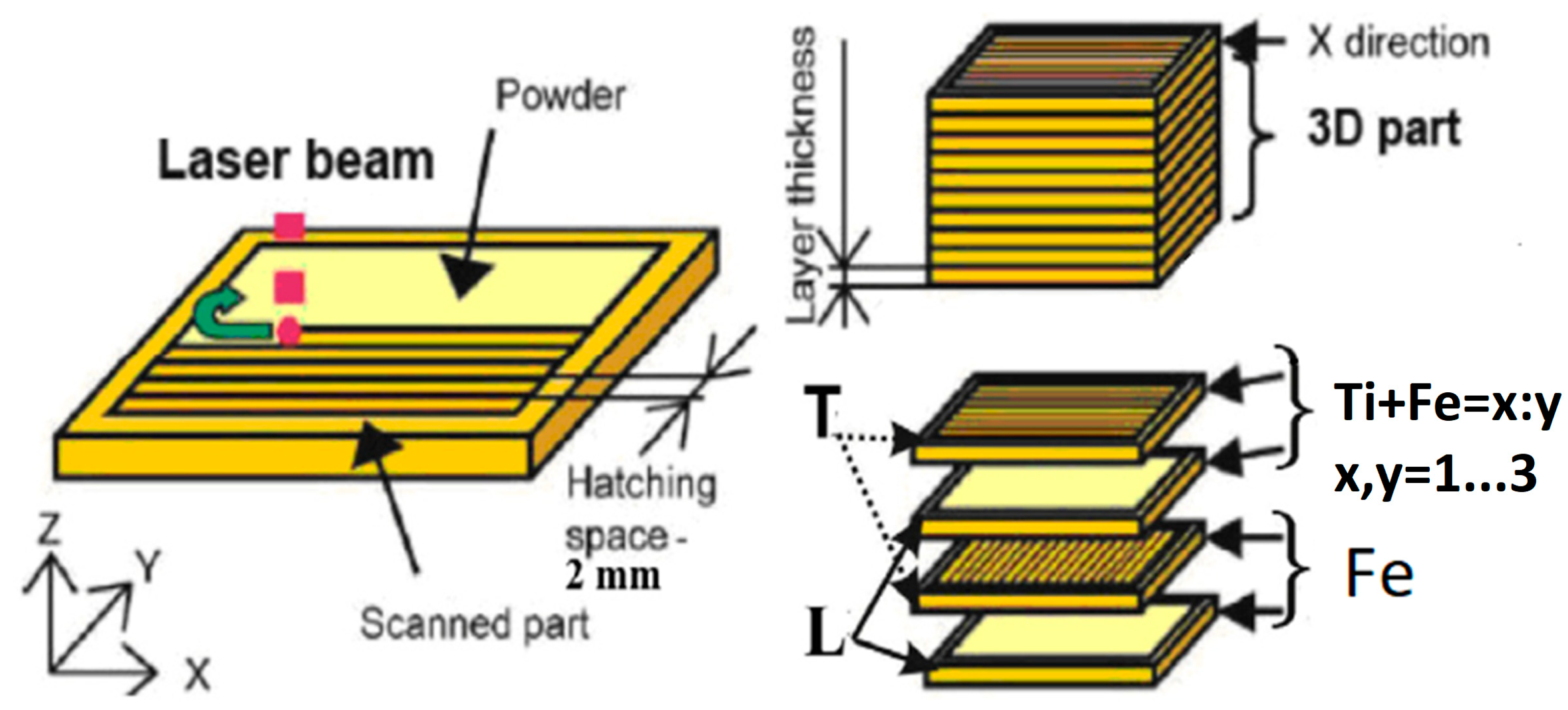
2.3. Scheme of Functional Graded Structure Fabrication

The method of graded structure fabrication used in the present study was schematically optimized and described in [20,24]. The laser scanning speed was 500 mm/min, and the laser beam spot diameter was 3 mm (Figure 1). The hatching distance was 2 mm, the layer depth was approximately 1 mm, and the powder feeding rate was approximately 10 g/min. Each second layer was formed on the bottom layer after turning it by 90 degrees.
The layers were made of Ti- and Fe-based powders on a related substrate according to the following strategy of alternation:
1st mode: P 1000 W;
      2 layers of Fe + 2 layers of Ti + Fe = 1:3;
2nd mode: P 1275 W
      2 layers of Ti + Fe = 1:3
      2 layers of Ti + Fe = 1:1
      2 layers of Ti + Fe = 3:1
3rd mode: P 1275 W
2 layers of Fe
2 layers of Ti + Fe = 1:3
2 layers of Ti + Fe = 1:1
The processing parameters were chosen based on preliminary experiments and the possibilities given by the equipment.

2.4. Microstructure Characterisation

After the etching, cross-sections of the multi-layered cladding samples were subjected to metallurgical analysis with optical microscopes (Carl Zeiss, Jena, Germany, Axioscope A1 and Neophot 30M), digital cameras, and microhardness (HV) tester FM (Wirtz-Buehler) and PMT-3M (RF). The phase composition of the produced structures was determined using X-ray diffraction (XRD) using a DRON-3 (Bourevestnik, St. Petersburg, FL, USA) diffractometer with Cu-Kα radiation. The morphology of the layers after the DED was studied with an LEO 1450 scanning electron microscope (Carl Zeiss Company) equipped with an energy-dispersive X-ray (EDX) analyzer (INCA Energy 300, Oxford Instruments).

3. Results

In accordance with the phase diagram of Fe-Ti, we expected to obtain the following stable intermetallide phases of iron titanium: Fe2Ti and FeTi. In addition, we found a eutectic mix of α-Fe-based solid solution + Fe2Ti from the Fe-side of the diagram and a eutectoid mix of FeTi + α-Ti-based solid solution for the Ti-side of the diagram.
The results of the optical metallography (OM) of the sample made by mode 1 are presented in Figure 1. In the central photo, typical microstructures and detail fragments at higher magnitude are given near the image and indexed with arrows.
The layered structure of the sample has pores and cracks inside the layers, rectangular to the Ti-rich surface, and on the borders between surface layers. The boundaries of the layers are not clearly manifested.
Scanning electron microscopy (SEM) results with EDX analysis of images from Figure 2 are combined in Table 1, where numbers demonstrate the atomic concentrations of elements in the analyzed area. Detailed information on EDX analysis is presented by the external link indexed in the Additional files section at the end of the article. We can see the presence of the following typical characteristics of the iron matrix structure: small inclusions of TiO2, dendrites of TiO2 + FeN, eutectic fragments, contours and fibers of Fe3C + TiC, and intereutectic grains of Fe2Ti. The seventh image represents the substrate.
The closer the investigated structural area is to the steel substrate, the fewer intermetallic grains and oxide balls, and the more eutectic islands appear; then, the eutectic becomes dominant, and after this, intermetallic grains appear, and they increase in number and occupy the whole structure. At the bottom of the sample, the chemical composition consists of the iron solid solution alloyed with titanium and carbon.
Figure 3 represents the layered structure of the DED of a Ti-Fe-layered sample produced by the first mode with corresponding values of microhardness. It is expected to produce an Fe2Ti intermetallic and Fe bond. However, in the structure, there are intermetallic grains surrounded by eutectic areas, titanium oxides, combined oxides, nitrides, and carbides, which may lead to brittleness. The result of brittleness is a large number of cracks inside and along the layers. The microhardness increases from 100 to 700 HV from the bottom to the top of the sample and repeats the layered structure. The first two millimeters characterize the microhardness of the substrate. It increases slightly at a distance of 1–2 mm, which may be associated with substrate hardening after high-speed laser heating and cooling. It can be seen that when the distance from the substrate becomes more than 2 mm, the dispersion of microhardness values increases significantly, which could be explained as follows. The DED process fabricated heterogeneous structures, where intermetallic phases in the iron matrix strengthen the top layers. In addition to the sedimentation of the intermetallic phases, pores and cracks were found in the mixes of carbides, which can lead to decreases in microhardness. The interpenetration of phases can also have an effect on the variation of the microhardness value.
Figure 4 represents the graded structure of the DED of a Ti-Fe-layered sample produced by the second mode, with the corresponding microstructure of the individual layers and areas. The layered structure of the sample also has large pores and cracks inside the layers and on the borders between them. The boundaries and thicknesses of the layers are not clear. The SEM of the sample produced by the second mode, as seen in Table 2, shows the presence of typical characteristics of the ferrotitanium alloy structure: intermetallic grains, dendrites, eutectoid fragments, and intereutectic grains, including those of the carbides. Phase composition dispersion of this sample also corresponds to the phase diagram Fe-Ti, including carbon, oxygen, and nitrogen. There are no individual structures of oxides, unlike in the sample produced by the first mode.
The microhardness of the sample produced by the second mode (Figure 5) repeats the layered structure of the sample. The substrate microhardness at the bottom is the same as that of the sample produced by the first mode. However, the top has a higher value, of up to 800–900 MPa (in comparison to the first mode, for which the maximum values were 650–690 MPa). The dispersion of values is small at up to 3 mm from the substrate in comparison to the first mode of production, and then dispersion is quite significant. A comparison of the microhardness values to the electron microscopy gives the highest level of microhardness for the FeTi intermetallic phase in a ferrotitanium alloy matrix. After achieving the maximum values, microhardness decreases, possibly causing pores and cracks.
Figure 6 represents the graded structure of the DED of a Ti-Fe layered sample produced by the third mode, along with the corresponding microstructure of the individual layers and microhardness. The layered structure of the sample also has pores and cracks inside the layers and on the borders between them. The boundaries and thicknesses of the layers are also not clearly visible.
The structural features of a layered Fe-Ti sample produced by the third mode after SEM are presented in Table 3. This is not a uniform structure, with areas of different shape and size. However, in all areas, the mix of carbide is found near the substrate. It is unclear if Ti-rich carbides exist, but Fe-rich carbides are obviously closer to the substrate. There are no eutectic structures. The first two millimeters characterize the microhardness after the laser hardening of the substrate. Next, the microhardness grows between 2 and 3 mm, and reaches stable value of near 400 HV0.1 between 3 and 4.5 mm. The maximum value of microhardness is 750–800 MPa near the top. Uniform values of microhardness are found at up to 4.5 mm from the substrate. The surface layer rich in titanium has increasing microhardness values due to cracks and pores. The combined analyses of the modes of the DED Fe-Ti layered samples produced, the physical properties of the initial materials, the final structure, and the microhardness show that pores are the result of the low heat conductivity of Ti. The low heat conductivity causes local overheating in the melting pool. It accumulates energy in the remelted powder mixture and begins to boil, entrapping the carrying and shielding gases. These gases become pores, which lead to decreases in microhardness. Therefore, the first recommendation is to decrease the energy of the DED process for Ti layers to avoid an excessive level of porosity.
Figure 7 shows the results of X-ray analysis of samples from (top) and substrate (sub) zones for all applied modes of DED. The analysis of diffractograms demonstrates the presence of Fe at reflecting angles of 2θ = 44, 65, and 82°. Diffractograms from the substrate area of the samples produced by deposition modes 1 and 2 have high levels of noise and wide dispersion of interference peaks. These are the result of high levels of residual stress and the disordering of the crystal lattice structure, as explained in [23,24]. A high level of noise is also observed in the top area of the sample produced by the first mode. Near interference angles of 45° (Figure 8), there are peaks of Fe2Ti and Fe3C phases. The peak of plate (110) of the FeTi phase is observed in the sample produced by the second mode to the left of the highest peak near interference 2θ angle 45 degrees.
Peaks of pure Ti and TiO2 are not found in research samples. This fact can be explained by the sensitivity of the X-ray method, which allows us to observe the phase presence when the concentration exceeds 5 mass %. In addition to this, the interaction of X-rays and various substances can lead to the particular or complete extinction of the interference lines. That is why the presence of TiC, Fe3C, FeTi, and TiO2 was revealed by SEM and was not registered by XRD.
Additionally, as shown in Figure 7, the maximum width of the largest peak is observed in the sample produced by the second mode, both at the top and in the substrate area. This demonstrates the large heterogeneity of gradient structures with residual micro-stress. This is the only sample that was produced without an Fe (steel) substrate with the increased energy level. Therefore, the initial Fe-layer result was more favorable due to the decrease in residual stress. Measurements of the microhardness of the samples indicate that as the distance from the substrate increases, the microhardness and its spread also increase. The latter indirectly points to local changes in residual stresses in the region of fragmentary precipitation of intermetallic compounds.

4. Discussion

Compared to published research, it was found in a study on the dissimilar friction stir welding of Ti-6Al-4V and AISI 304 stainless steel [27] that several intermetallic phases were observed in the border structure, leading to the formation of cracks near the welding line. The solid-state bonding technique of commercial pure titanium and stainless steel 17-4 (Fe-16Cr-4Ni-3-Cu) is performed either without any interlayer [28] or with the presence of an interlayer, in which case, the formation of intermetallic phases is often inevitable.
The chemical compositions of layers in the diffusion zone were determined by energy-dispersive spectroscopy, and the formation of intermetallics such as σ phase, Fe2Ti, FeTi, Cr2Ti, χ, α-Fe, α-Ti, and β-Ti phases were found. These intermetallics were confirmed by an X-ray diffraction technique. The volume fraction of the intermetallics increases and bond strength drops with the rise in joining temperature in the interval 850–950 °C.
In [29], the possibility of bonding commercial pure titanium and AISI 304 stainless steel by laser welding is investigated. The authors found that intermetallic compounds that form of due to the interlayer elements are very reactive, and the presence of oxides has led to brittle failure with clad interlayers. Similar results were achieved in [30,31], confirming that fusion-based welding and deposition techniques (including laser welding) are highly susceptible to the formation of intermetallic compounds. In summary, it is very difficult to achieve an integrated Ti-6Al-4V/AISI 304 joint with many of the commercially available welding techniques, due to the high tendency of alloying elements to form brittle intermetallic compounds. Intermetallic phases, including TiFe and TiFe2, formed in the Ti-6Al-4V/AISI 304 joints, can act as sites for crack initiation and propagation, significantly decreasing the mechanical properties [32]. This obviously increases brittleness due to the formation of intermetallic phases. Therefore, it appears that the integrity of Ti-6Al-4V/AISI 304 joints can be greatly improved by reducing or eliminating intermetallic phases [33,34,35].
The results [36] show that the prepared Fe-based laser beam coating on titanium substrate has a high hardness of about 860 HV0.2 and exhibits an average wear rate of (0.70 −2.32) × 10−6 mm3/(N·m), showing that the Fe-based coating can greatly improve the wear resistance of the pure Ti substrate.
Ti-Fe intermetallics analysis and control in joining titanium alloy and stainless steel by laser metal deposition performed in [37] demonstrates an XRD pattern that indicates the main intermetallic phases are Fe2Ti and FeTi. The brittleness and hardness of these two substances caused the direct fracture and clear cracking under thermal stress and excessive generation of strains of the interface arising from the thermal expansion difference of titanium and stainless steel alloys. Measuring Vickers hardness from the Ti6Al4V side to SS316 side shows the that values near the crack area are much higher than those of both the base metals. Therefore, the compounds near the crack region have poor plasticity. Maximum hardness was achieved at a level of 1130 VHN near the crack.
Cui mentioned that the brittle intermetallic compounds FeTi and Fe2Ti can be the subject of extensive crack formation and propagation [38]. Additionally, even a small amount of carbon admixture in powder can cause the precipitation of carbides along grain boundaries, which introduces additional internal stress at the interface of dissimilar materials. A source of carbon may be iron of technical purity, or else titanium powder Grade 2 (which can contain up to 0.08 mass %). The authors of [21,22,23] use intermediate carbon-free layers of Cu, V, and Cr to avoid carbide sedimentation and its penetration into the structure. The mechanism of precipitation formation in interface can be described as a thermodynamic process. The changes in Gibbs free energy for TiC, Fe3C, Fe2Ti, and FeTi are functions of temperature. The lowest value of ΔG among them is for the formation of TiC in the temperature range of 1000–2000 K [39]. Therefore, the probability of Fe3C formation is lower than that of TiC [39,40].
To quantify the influence of the interfacial interface on the stress state, one can refer to the continuity preservation condition (CPC) and the crack initiation criteria CIC [41].
The first parameter, depending on the microelement composition, characterizes the dimensionless ratio of thermodynamic quantities at a local point at which destruction does not occur. The second parameter determines the amount of excess CPC at the fracture boundary compared to its safe value outside the fracture. CPC and CIC can be calculated from dependencies (1) and (2).
C P C v / w = 1 24,304 C Ω v + C Ω w n w α m w ( T m w ) 3 / 2 + n v α m v ( T m v ) 3 / 2 ( 1 T 0 1 T m v )
C P C v = 1 24,304 C Ω v n v α m v T m v ( ( T m v T 0 ) 1 / 2 1 )
C I C = | C P C v / w C P C v | C P C v
In dependencies (1)–(3):
C P C v is the continuity preservation condition for the phase of the matrix;
C P C v / w is the continuity preservation condition for the interface between the matrix and selection phases;
C I C is the crack initiation criteria, which is the relative value of exceeding the permissible level of CPC in the area of the phase interface;
C Ω v , C Ω w is the isochoric molar heat capacities of the matrix phase and the selection phase;
T 0 is the temperature of normal conditions, and T m v is the melting temperature of the matrix phase;
α m v , α m w are the coefficients of linear expansion of the matrix phase and the selection phase;
n v , n w are the total number of atoms in the chemical compound of the matrix phase and the selection phase according to the rule of the Magnus–Lindemann rule [42] (for FeTi nv = 2, for Fe3C nw = 4, for TiC nw = 2).
Calculations of CPC and CIC parameters in the area of the TiC/FeTi and Fe3C/FeTi phase interfaces are presented in Table 4. The thermodynamic parameters of the phases from Table 4 were taken from the experimental data of other researchers.
The calculated values of CIC = 1.6 for TiC/FeTi and CIC = 1.4 for Fe3C/FeTi phase interfaces (Table 4) show that the permissible level of the CPC parameter, which characterizes the safe level of internal stresses in the area of local discontinuity, is exceeded by 140%. So, this CIC value imposes a condition for crack formation.
This conclusion is confirmed by the spreading of X-ray diffraction peaks in the region of the Fe3C phase (Figure 7), which indicates the presence of residual microstresses.

5. Conclusions

To summarize our results, the DED of Fe and Ti powders with a laser beam power of 1000–1275 W is generally suitable for producing a two-component Fe-Ti system layered composite, reinforced with intermetallic compounds, oxides, carbides and nitrides. The experimental results by the DED fabrication in the gradient Fe-Ti mixtures are discussed, where the intermetallic phases cause the microhardness and the dispersion of values to increase, but pores and cracks are evident and decrease the microhardness.
It has been shown that:
-
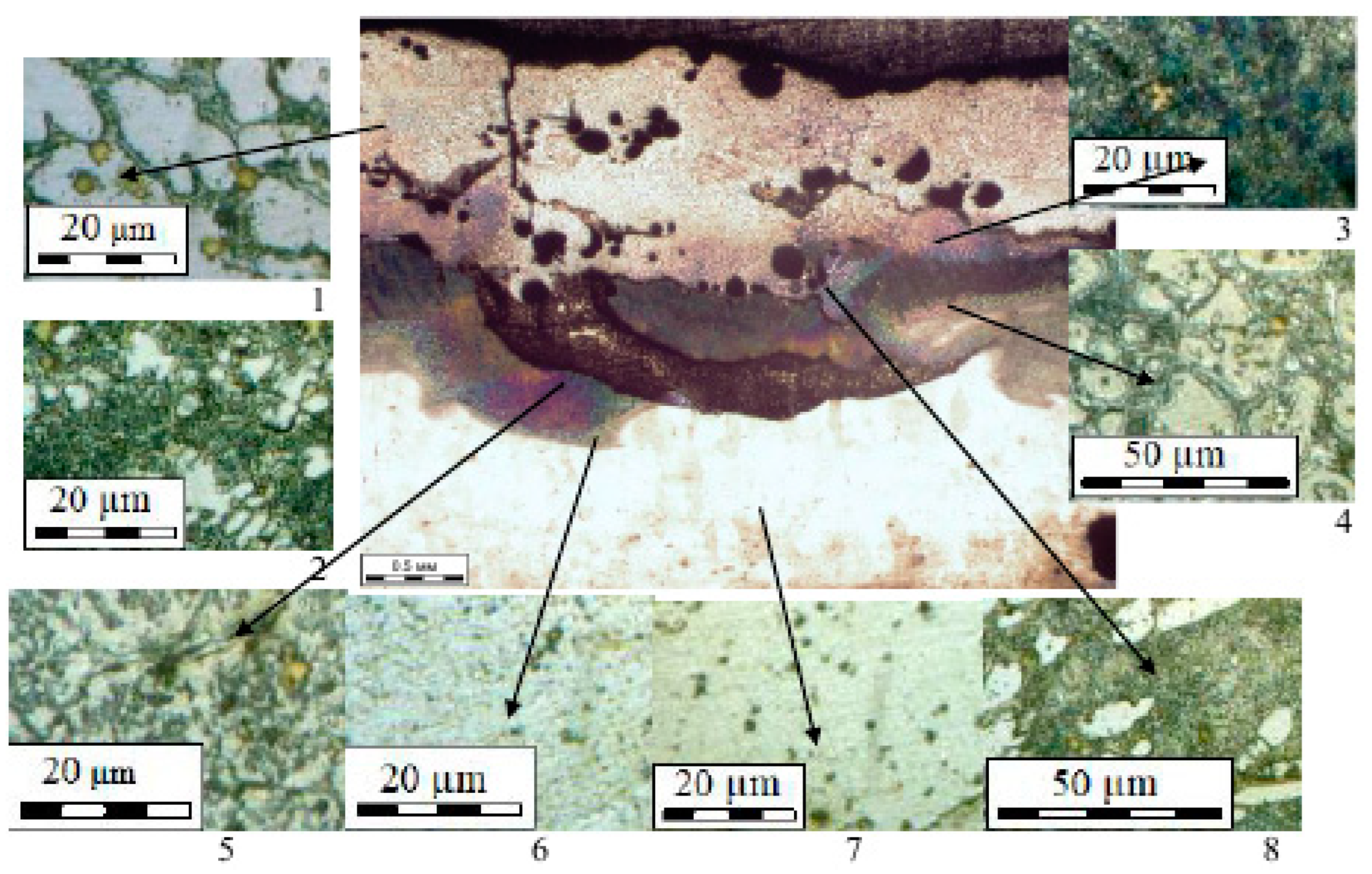
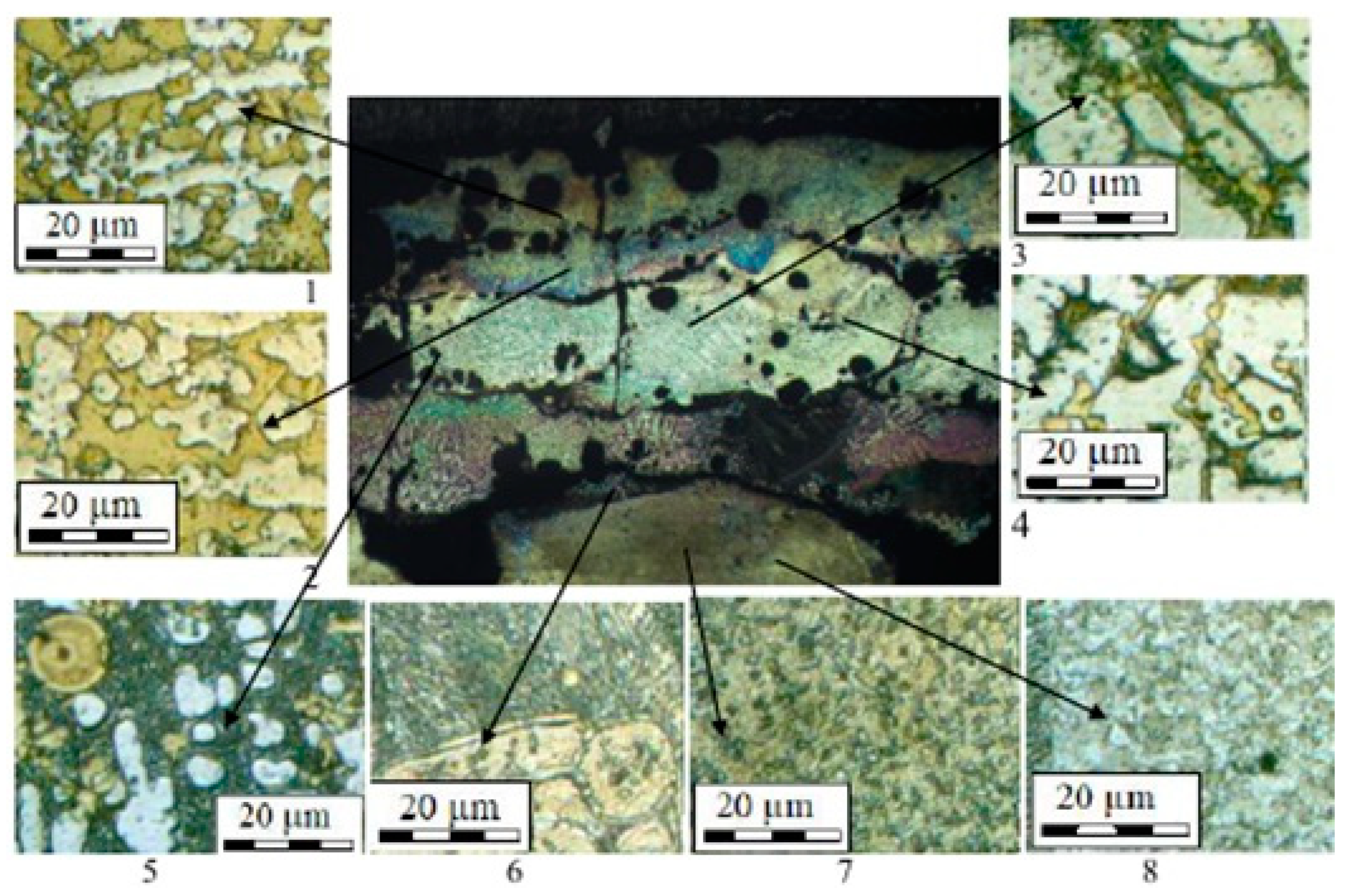
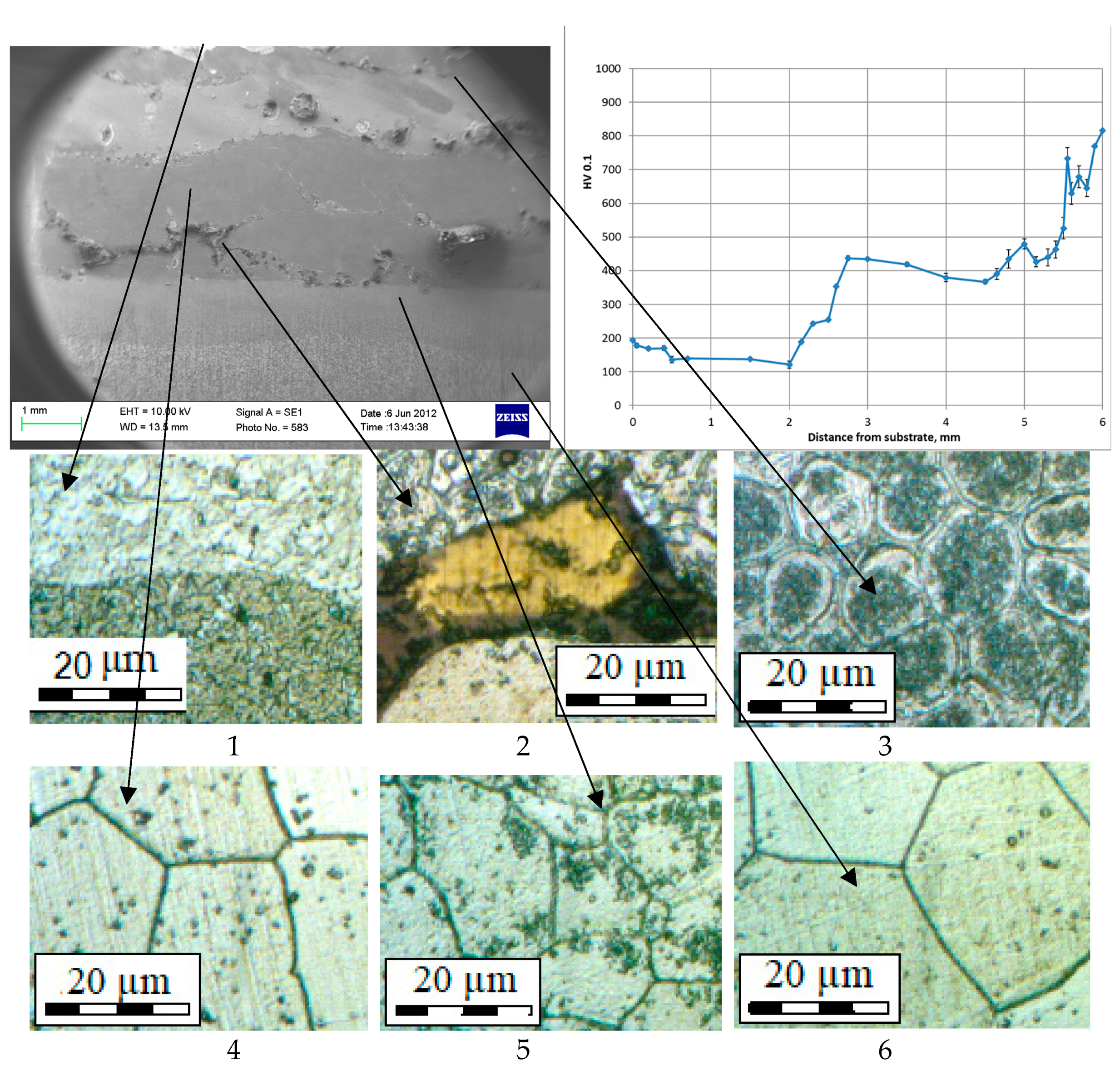
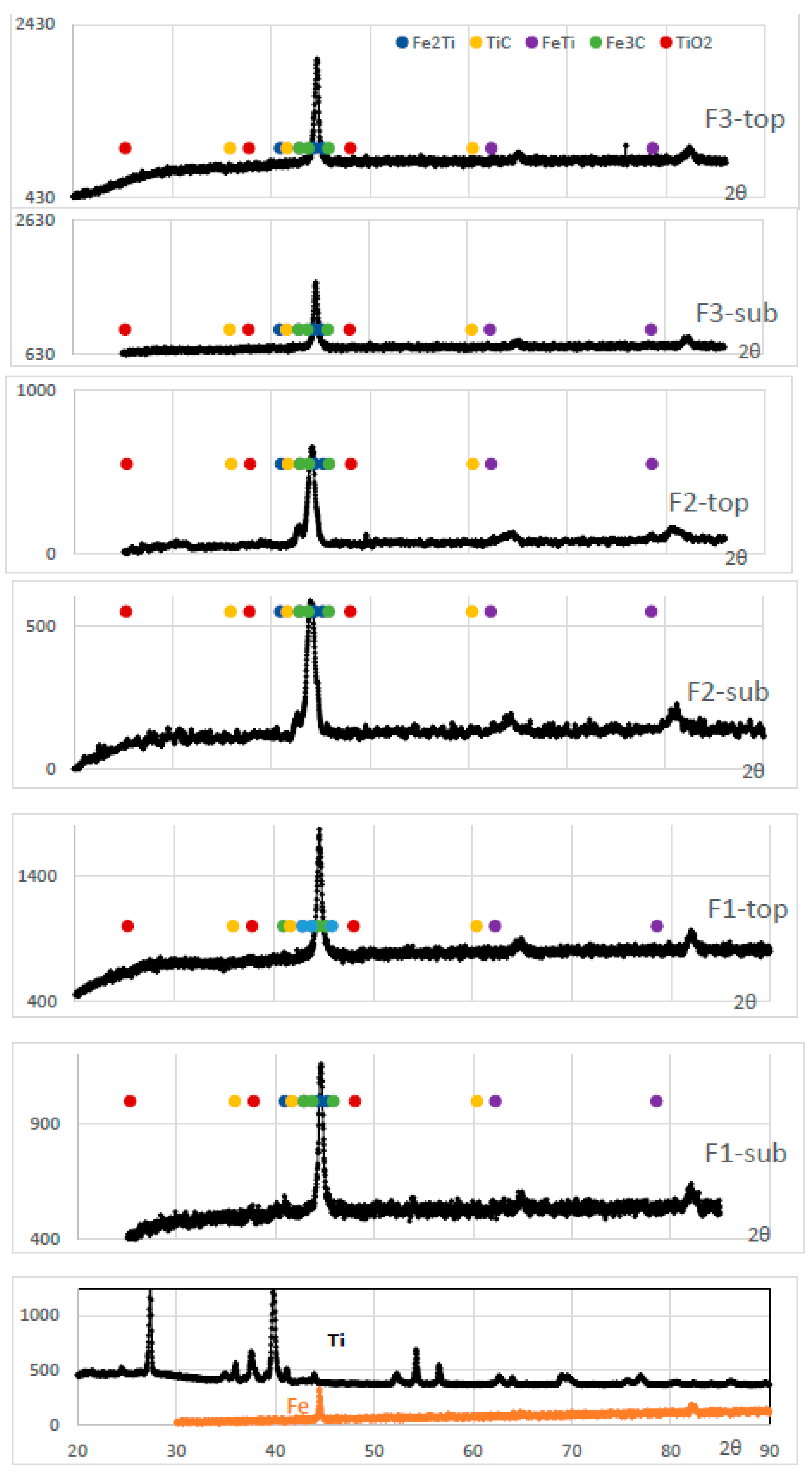
The DED process has the tendency to form heterogeneous structures with intermetallic phases of FeTi, Fe2Ti eutectoids, complex titanium oxides and nitrides, and iron carbides.
-
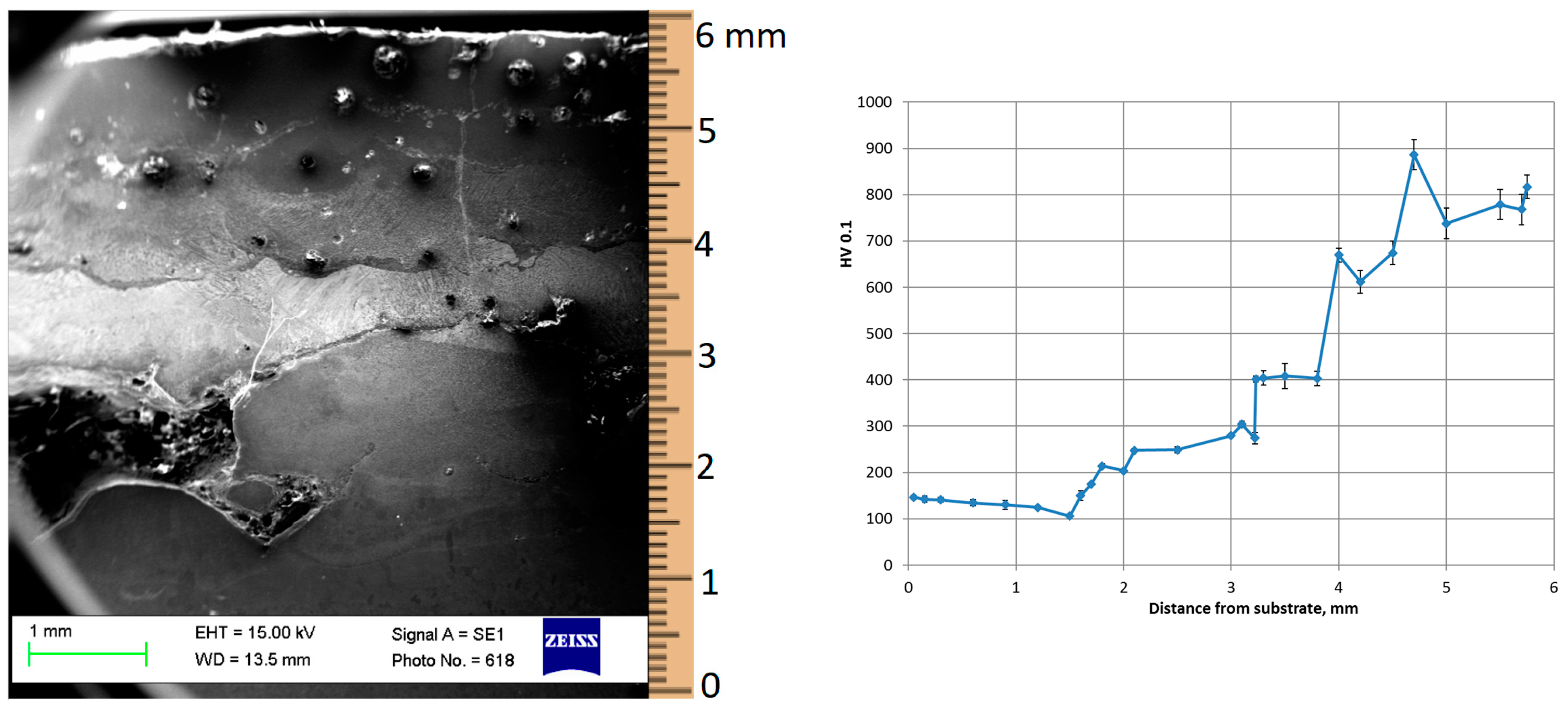
The microhardness growth from 150 HV to 900 HV was obtained for the all samples due to the precipitation of brittle intermetallic phases in the gradient Fe-Ti system during the DED. The dispersion of microhardness values becomes significant in Ti-rich areas; there, pores and cracks are found. Titanium could pull carbon from the substrate and collect nitrogen and oxygen from the air for the formation of oxinitrides.
-
The level of the power for the DED process for Ti-rich layers has to be less than for Fe-rich zones due to the poor heat conductivity of Ti.
-
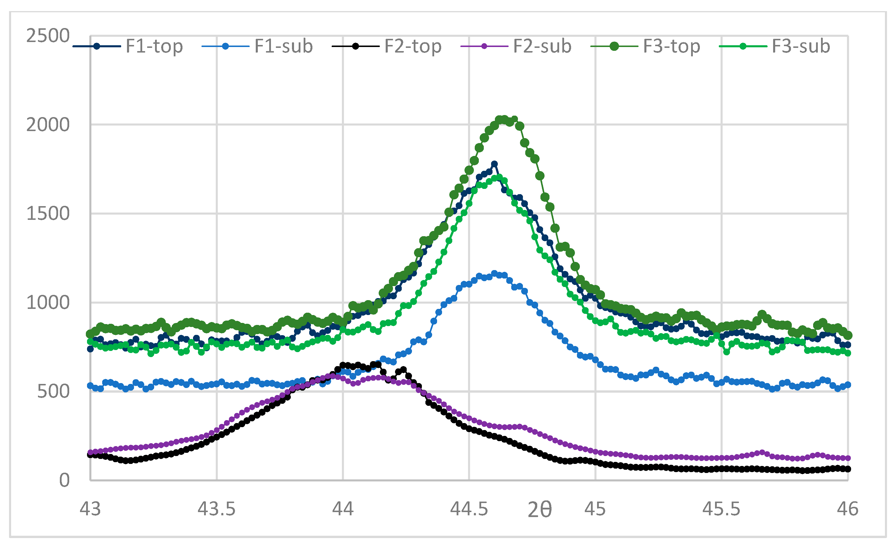
The presence of initial steel substrate results in a lower level of residual microstress.
-
The increased concentration of Ti up to Ti + Fe = 3:1 on the Fe- and Fe + Ti substrate with concentrations of Ti + Fe = 1:1 and Ti + Fe = 1:3 lead to increasing hardness and distribution, but also increasing residual microstress.
-
The calculated values of crack initiation criteria CIC = 1.6 for TiC/FeTi and CIC = 1.4 for Fe3C/FeTi phase interfaces exceeds the permissible level of the continuity preservation condition CPC parameter, which characterizes the safe level of internal stresses in the area of local discontinuity, by 140%.
The power during the direct energy deposition of titanium layers should be decreased from 1275 to 1000 W, and an Fe substrate should be used, which would allow a reduction in residual stress, pores and cracks.

Author Contributions

Conceptualization, I.S.; methodology, I.S. and E.N.; sample characterization, N.K.; validation, N.K., A.K. and E.N.; investigation, I.S. and N.K.; data curation, I.S., N.K., A.K. and E.N.; writing—original draft preparation, E.N.; writing—review and editing, E.N., I.S. and A.K.; visualization, N.K. and E.N.; project administration, I.S. and A.K.; funding acquisition, A.K. All authors have read and agreed to the published version of the manuscript.

Funding

This research was funded by the Russian Science Foundation, grant number 20-69-46070.

Institutional Review Board Statement

Not applicable.

Informed Consent Statement

Not applicable.

Data Availability Statement

The supporting information can be downloaded at: https://github.com/eanosova76/Fe-Ti-DED-EDS-data.git.

Acknowledgments

The authors are thankful to Floran Missemer for his help with the DED installation during AM process and Professor Igor Smurov for his kind invitation and administrative support at DIPI (ENISE, France).

Conflicts of Interest

The authors declare no conflict of interest.

References

  1. Zhou, S.; Zeng, X. Growth characteristic and mechanism of carbides precipitated in WC-Fe composite coatings by laser induction hybrid rapid cladding. J. Alloys Compd. 2010, 505, 685–691. [Google Scholar] [CrossRef]
  2. Comisso, N.; Davolio, G.; Soragni, E.; Mengoli, G. The cycle life of 50/50 TiFe alloy electrodes for charge storage. J. Electroanal. Chem. 2001, 512, 92–100. [Google Scholar] [CrossRef]
  3. Patel, A.K.; Duguay, A.; Tougas, B.; Schade, C.; Sharma, P.; Huot, J. Microstructure and first hydrogenation properties of TiFe alloy with Zr and Mn as additives. Int. J. Hydrogen Energy 2020, 45, 787–797. [Google Scholar] [CrossRef]
  4. Abrashev, B.; Spassov, T.; Bliznakov, S.; Popov, A. Microstructure and electrochemical hydriding/dehydriding properties of ball-milled TiFe-based alloys. Int. J. Hydrogen Energy 2010, 35, 6332–6337. [Google Scholar] [CrossRef]
  5. Verma, J.; Taiwade, R.V. Effect of welding processes and conditions on the microstructure, mechanical properties and corrosion resistance of duplex stainless steel weldments—A review. J. Manuf. Process. 2017, 25, 134–152. [Google Scholar] [CrossRef]
  6. Buffa, G.; Fratini, L.; Micari, F. Mechanical and microstructural properties prediction by artificial neural networks in FSW processes of dual phase titanium alloys. J. Manuf. Process. 2012, 14, 289–296. [Google Scholar] [CrossRef]
  7. Tanaka, K.; Nakazawa, T.; Sakairi, K.; Sato, Y.; Kokawa, H.; Omori, T.; Ishida, K. Feasibility of Iridium Containing Nickel Based Superalloy Tool to Friction Stir Spot Welding of High Strength Steel. In Friction Stir Welding and Processing IX; Springer: Berlin/Heidelberg, Germany, 2017; pp. 29–35. [Google Scholar]
  8. Bakavos, D.; Prangnell, P.B. Mechanisms of joint and microstructure formation in high power ultrasonic spot welding 6111 aluminium automotive sheet. Mater. Sci. Eng. A 2010, 527, 6320–6334. [Google Scholar] [CrossRef]
  9. Gussone, J.; Bugelnig, K.; Barriobero-Vila, P.; da Silva, J.C.; Hecht, U.; Dresbach, C.; Sket, F.; Cloetens, P.; Stark, A.; Schell, N.; et al. Ultrafine eutectic Ti-Fe-based alloys processed by additive manufacturing—A new candidate for high temperature applications. App. Mat. Today 2020, 20, 100767. [Google Scholar] [CrossRef]
  10. Shishkovsky, I.; Missemer, F.; Smurov, I. Direct metal deposition of functional graded structures in Ti-Al system. Phys. Procedia 2012, 39, 382–391. [Google Scholar] [CrossRef]
  11. Ocylok, S.; Weisheit, A.; Kelbassa, I. Functionally graded multi-layers by laser cladding for increased wear and corrosion protection. Phys. Procedia 2010, 5, 359–367. [Google Scholar] [CrossRef]
  12. Shishkovsky, I.; Missemer, F.; Smurov, I. Metal matrix composites with ternary intermetallic inclusions fabricated by laser direct energy deposition. Compos. Struct. 2018, 183, 663–670. [Google Scholar] [CrossRef]
  13. Shishkovsky, I.; Smurov, I. Titanium base functional graded coating via 3D laser cladding. Mater. Lett. 2012, 73, 32–35. [Google Scholar] [CrossRef]
  14. Shishkovsky, I.; Missemer, F.; Kakovkina, N.; Smurov, I. Intermetallics synthesis in the Fe-Al system via layer-by layer 3D laser cladding. Crystals 2013, 3, 517–529. [Google Scholar] [CrossRef]
  15. Bo, H.; Wang, J.; Duarte, L.; Leinenbach, C.; Liu, L.; Liu, H.; Jin, Z. Thermodynamic re-assessment of Fe−Ti binary system. Trans. Nonferrous Met. Soc. China 2012, 22, 2204–2211. [Google Scholar] [CrossRef]
  16. Sharma, R.K.; Das, R.K.; Kumar, S.R. Microstructure, adhesion and erosion properties of Fe-Cr-Ti-Mo-C-Si coating with varying Titanium. Mater. Today Commun. 2021, 26, 101826. [Google Scholar] [CrossRef]
  17. Kocaman, E.; Kılınç, B.; Şen, Ş.; Şen, U. In-situ TiB2 and Fe2Ti intermetallic assisted hard coatings by Fe-Ti-B based hardfacing electrodes. J. Alloys Comp. 2022, 900, 163478. [Google Scholar] [CrossRef]
  18. Baeslack, W.A.; Gerken, J.M.; Cross, J.H.C.; Liu, P.S.; Monses, J.C.; Schley, J.; Showalter, L. Welding Handbook 4, 8th ed.; Gerken, J.M., Ed.; American Welding Society: Miami, FL, USA, 1998; pp. 488–540. [Google Scholar]
  19. Lathabai, S.; Jarvis, B.L.; Barton, K.J. Comparison of keyhole and conventional gas tungsten arc welds in commercially pure titanium. Mater. Sci. Eng. A 2001, 299, 81–93. [Google Scholar] [CrossRef]
  20. Ren, D.; Jiang, Y.; Hu, X.; Zhang, X.; Xiang, X.; Huang, K.; Ling, H. Investigation of tensile and high cycle fatigue failure behavior on a TIG welded titanium alloy. Intermetallics 2021, 132, 107115. [Google Scholar] [CrossRef]
  21. Cooke, K.O.; Richardson, A.; Khan, T.I.; Shar, M.A. High-Temperature Diffusion Bonding of Ti–6Al–4V and Super-Duplex Stainless Steel Using a Cu Interlayer Embedded with Alumina Nanoparticles. J. Manuf. Mater. Process. 2020, 4, 3. [Google Scholar] [CrossRef]
  22. Li, W.; Liou, F.; Newkirk, J.; Brown Taminger, K.M.; Seufzer, W.J. Ti6Al4V/SS316 multi-metallic structure fabricated by laser 3D printing and thermodynamic modeling prediction. Int. J. Adv. Manuf. Technol. 2017, 92, 4511–4523. [Google Scholar] [CrossRef]
  23. Bobbio, L.D.; Bocklund, B.; Otis, R.; Borgoni, J.P.; Dillon, R.P.; Shapiro, A.A.; McEnerney, B.; Liu, Z.; Beese, A.M. Characterization of a functionally graded material of Ti-6Al-4V to 304L stainless steel with an intermediate V section. J. Alloys Compd. 2018, 742, 1031–1036. [Google Scholar] [CrossRef]
  24. Shishkovsky, I.V. Laser Controlled Intermetallics Synthesis during Surface Cladding. In Laser Surface Engineering. Processes and Applications; Lawrence, J., Waugh, D.G., Eds.; Woodhead Publishing Series in Electronic and Optical Materials; Elsevier Science & Technology: Oxford, UK, 2015; Chapter 11; pp. 237–286. ISBN 978-1-78242-074-3. [Google Scholar] [CrossRef]
  25. Wu, L.; Zhou, Z.; Zhang, K.; Zhang, X.; Wang, G.; Zhang, F.; Wu, L. Reinforced mechanical properties of plasma-sprayed Fe-based amorphous composite coatings by in-situ TiNx/TiOy. Ceram. Int. 2022, 48, 36305–36317. [Google Scholar] [CrossRef]
  26. Shang, H.; Zhang, Y.; Gao, J.; Zhang, W.; Wei, X.; Yuan, Z.; Li, Y. Characteristics of electrochemical hydrogen storage using TieFe based alloys prepared by ball milling. Int. J. Hydrogen Energy. 2022, 47, 1036–1047. [Google Scholar] [CrossRef]
  27. Astarita, A.; Scherillo, F.; Curioni, M.; Aprea, P.; Impero, F.; Squillace, A.; Zhou, X. Study of the linear friction welding process of dissimilar Ti-6Al-4Vestainless steel joints. Mater. Manuf. Process. 2016, 31, 2115–2122. [Google Scholar] [CrossRef]
  28. Kundu, S.; Ghosh, M.; Chatterjee, S. Diffusion bonding of commercially pure titanium and 17-4 precipitation hardening stainless steel. Mater. Sci. Eng. 2006, 428, 18–23. [Google Scholar] [CrossRef]
  29. Shanmugarajan, B.; Padmanabham, G. Fusion welding studies using laser on Ti-SS dissimilar combination. Opt. Laser Eng. 2012, 50, 1621–1627. [Google Scholar] [CrossRef]
  30. Chen, S.; Zhang, M.; Huang, J.; Cui, C.; Zhang, H.; Zhao, X. Microstructures and mechanical property of laser butt welding of titanium alloy to stainless steel. Mater. Des. 2014, 53, 504–511. [Google Scholar] [CrossRef]
  31. Reichardt, A.; Dillon, R.P.; Borgonia, J.P.; Shapiro, A.A.; McEnerney, B.W.; Momose, T.; Hosemann, P. Development and characterization of Ti-6Al-4V to 304L stainless steel gradient components fabricated with laser deposition additive manufacturing. Mater. Des. 2016, 104, 404–413. [Google Scholar] [CrossRef]
  32. Deng, Y.; Sheng, G.; Xu, C. Evaluation of the microstructure and mechanical properties of diffusion bonded joints of titanium to stainless steel with a pure silver interlayer. Mater. Des. 2013, 46, 84–87. [Google Scholar] [CrossRef]
  33. Kundu, S.; Chatterjee, S. Characterization of diffusion bonded joint between titanium and 304 stainless steels using a Ni interlayer. Mater. Charact. 2008, 59, 631–637. [Google Scholar] [CrossRef]
  34. Kundu, S.; Chatterjee, S. Evolution of interface microstructure and mechanical properties of titanium/304 stainless steel diffusion bonded joint using Nb interlayer. ISIJ Int. 2010, 50, 1460–1465. [Google Scholar] [CrossRef]
  35. Kundu, S.; Mishra, B.; Olson, D.L.; Chatterjee, S. Interfacial reactions and strength properties of diffusion bonded joints of Ti64 alloy and 17-4PH stainless steel using nickel alloy interlayer. Mater. Des. 2013, 51, 714–722. [Google Scholar] [CrossRef]
  36. Chen, J.; Guo, C.; Zhou, J. Microstructure and tribological properties of laser cladding Fe-based coating on pure Ti substrate. Trans. Nonferrous Met. Soc. China 2012, 22, 2171–2178. [Google Scholar] [CrossRef]
  37. Li, W.; Yan, L.; Karnati, S.; Liou, F.; Newkirk, J.; Brown Taminger, K.M.; Seufzer, W.J. Ti-Fe intermetallics analysis and control in joining titanium alloy and stainless steel by Laser Metal Deposition. J. Mater. Process. Technol. 2017, 242, 39–48. [Google Scholar] [CrossRef]
  38. Cui, D.; Mohanta, A.; Leparoux, M. Interface Control in Additive Manufacturing of Dissimilar Metals Forming Intermetallic Compounds-Fe-Ti as a Model System. Materials 2020, 13, 4747. [Google Scholar] [CrossRef]
  39. Wachowski, M.; Gloc, M.; Ślęzak, T.; Płociński, T.; Kurzydłowski, K.J. The Effect of Heat Treatment on the Microstructure and Properties of Explosively Welded Titanium-Steel Plates. J. Mater. Eng. Perform. 2017, 26, 945–954. [Google Scholar] [CrossRef]
  40. Emamian, A.; Corbin, S.; Khajepour, A. In-Situ Deposition of Metal Matrix Composite in Fe-Ti-C System Using Laser Cladding Process; IntechOpen: Rijeka, Croatia, 2011. [Google Scholar] [CrossRef]
  41. Khaimovich, A.; Shishkovsky, I.; Erisov, Y.; Agapovichev, A.; Smelov, V.; Razzhivin, V. Research on Cracked Conditions in Nickel Chrome Alloy Ni50Cr33W4.5Mo2.8TiAlNb, Obtained by Direct Laser Deposition. Metals 2022, 12, 1902. [Google Scholar] [CrossRef]
  42. Moracheskij, A.G.; Sladkov, I.B. Thermodynamic Calculations in Metallurgy; Metallurgiya: Moscow, Russia, 1985. [Google Scholar]
  43. Zhu, L.; Friák, M.; Udyansky, A.; Ma, D.; Schlieter, A.; Kühn, U.; Eckert, J.; Neugebauer, J. Ab initio based study of finite-temperature structural, elastic and thermodynamic properties of FeTi. Intermetallics 2014, 45, 11–17. [Google Scholar] [CrossRef]
  44. Hallstedt, B.; Djurovic, D.; von Appen, J.; Dronskowski, R.; Dick, A.; Körmann, F.; Hickel, T.; Neugebauer, J. Thermodynamic properties of cementite (Fe3C). Calphad 2010, 34, 129–133. [Google Scholar] [CrossRef]
  45. Wood, I.G.; Vocadlo, L.; Knight, K.S.; Dobson, D.P.; Marshall, W.G.; Price, G.D.; Brodholt, J. Thermal expansion and crystal structure of cementite, Fe3C, between 4 and 600 K determined by time-of-flight neutron powder diffraction. J. Appl. Crystallogr. 2004, 37, 82–90. [Google Scholar] [CrossRef]
  46. Murray, J.-L. Phase Diagrams of Binary Titanium Alloys; ASM International: Materials Park, OH, USA, 1987. [Google Scholar]
  47. Dang, D.; Fan, J.L.; Gong, H. Thermodynamic and mechanical properties of TiC from ab initio calculation. J. Appl. Phys. 2014, 116, 033509. [Google Scholar] [CrossRef]
Figure 1. Schematic of the multi component graded structure fabrication by DED. Longitudinal—L; transversal—T [10,24,25,26].
Jmmp 07 00066 g001
Figure 2. Optical micrographs showing the SEM microstructures of the DED of a Ti-Fe multilayer sample: central image has a magnitude of 25; detailed pictures have magnitudes of 800.
Jmmp 07 00066 g002
Figure 3. Optical micrographs and microhardness behavior of the DED of a Ti-Fe-graded layered sample produced by the 1st mode.
Jmmp 07 00066 g003
Figure 4. Optical micrographs showing the typical microstructures of the DED of a Ti-Fe multilayer sample: central image has a magnitude of 25; detailed pictureds have magnitudes of 800.
Jmmp 07 00066 g004
Figure 5. SEM micrograph and microhardness behavior of the DED of a Ti-Fe-graded layered sample produced by the 2nd mode.
Jmmp 07 00066 g005
Figure 6. SEM and optical micrographs of the typical structure and microhardness of the DED of a Ti-Fe graded multilayer sample produced by the 3rd mode.
Jmmp 07 00066 g006
Figure 7. XRD patterns of the initial powders and final DED of a Ti-Fe-graded multilayer sample produced by all regimes.
Jmmp 07 00066 g007
Figure 8. XRD pattern for the DED of a Ti-Fe-graded multilayer sample produced by all regimes, detailed for area of 2θ = 45°.
Jmmp 07 00066 g008
Table 1. Structural components of graded structures from Figure 2.
Number of ImageGrains (Grey)Eutectoids (Dark)Spheres (Yellow)Dendrites (Light)Including (Light Dots)
1Fe:Ti = 7:3Fe:Ti:C = 8:1:1Ti:O = 4:6Fe:Ti:O:N = 1:4:2:3Ti:O:N = 4:4:2
2Fe:Ti = 7:3Fe:Ti:C = 8:1:1Ti:O = 4:6Fe:Ti:O:N = 1:4:2:3
3Fe:Ti = 7:3Fe:Ti:C = 8:1:1Ti:O = 4:6Fe:Ti:O:N = 1:4:2:3
4Fe:Ti = 7:3Fe:Ti:C = 8:1:1 Ti:O:N = 4:5:1
5Fe:Ti = 7:3Fe:Ti:C = 8:1:1
6 Fe:Ti:O:C = 65:15:10:10
7 Fe:Ti = 85:15 Fe:Ti = 85:5
8Fe:Ti = 95:5Fe:Ti:C = 8:1:1
Table 2. Structural components of graded structures from Figure 4 (2nd mode).
Number of ImageGrains (Dark Yellow Islands)Eutectoids (Dark Colored)Spheres (Yellow)Dendrites (Light Yellow)
1Fe:Ti = 4:6 Fe:Ti = 5:5
2Fe:Ti = 4:6 Fe:Ti = 5:5
3Fe:Ti = 4:6 Fe:Ti = 5:5
4Fe:Ti = 4:6 Fe:Ti = 5:5, Ti:O:N = 4:4:1
5Fe:Ti:C = 6:2:2Fe:Ti:C = 8:1:1Ti:O = 4:6
6Fe:Ti:C = 80:4:15Fe:Ti:C = 8:1:1 Fe:Ti = 7:3
7Fe:Ti:C = 80:4:15
8Fe:Ti:C = 80:4:15
Table 3. Structural components of graded structures from Figure 6.
Number of ImageGrains (Light Grey)Including (Dark Marked)
1Fe:Ti = 4:6Ti:O = 4:6
2Fe:Ti = 4:6
3Fe:Ti:C = 80:4:15Fe:Ti:C = 80:6:20
4Fe:Ti = 4:6
5Fe:Ti:C = 80:4:15Fe:Ti:C = 80:6:20
6Fe:Ti:C = 80:6:20
Table 4. CPC and CIC parameters in the area of the TiC/FeTi and Fe3C/FeTi phase interfaces.
FeTiTiCFe3C
Isobaric   heat   capacity   C Ω v , C Ω w , J/mol/K22 [43]34 [44]110 [45]
Melting
Temperature, Tm, K
1383 [45]3363 [46]1147 [45]
CTE 0.90 × 10⁻⁵ [47]0.42 × 10⁻⁵ [45]1.90 × 10⁻⁵ [46]
CPC continuityconditionCPCv for FeTiCPC v/w for interface of phases FeTi/TiCCPC v/w for interface of phases FeTi/Fe3C
0.0065 (Exp. 1)0.0169 (Exp. 2)0.0169 (Exp. 2)
CIC 1.6 (Exp. 3)1.4 (Exp. 3)
Disclaimer/Publisher’s Note: The statements, opinions and data contained in all publications are solely those of the individual author(s) and contributor(s) and not of MDPI and/or the editor(s). MDPI and/or the editor(s) disclaim responsibility for any injury to people or property resulting from any ideas, methods, instructions or products referred to in the content.

