Article

Tribological Properties of Multilayer CVD Coatings Deposited on SiAlON Ceramic Milling Inserts

1
Industrial Doctorate Centre in Machining Science, Advanced Manufacturing Research Centre, The University of Sheffield, Catcliffe, Rotherham S60 5TZ, UK
2
Department of Mechanical Engineering, The University of Sheffield, Mappin Street, Sheffield S1 3JD, UK
3
Advanced Manufacturing Research Centre, The University of Sheffield, Advanced Manufacturing Park, Catcliffe, Rotherham S60 5TZ, UK
*
Author to whom correspondence should be addressed.
J. Manuf. Mater. Process. 2023, 7(2), 67; https://doi.org/10.3390/jmmp7020067
Submission received: 24 January 2023 / Revised: 9 March 2023 / Accepted: 13 March 2023 / Published: 15 March 2023
(This article belongs to the Special Issue Advances in Metal Cutting and Cutting Tools)

Abstract

:
This work characterises the structure and mechanical properties, such as adhesion, of two different chemical vapour deposition (CVD) coatings deposited onto silicon aluminium oxynitride (Si3N4 + Al2O3 + Y2O3) round (RNGN) milling cutter tooling inserts. These inserts are often known by the trade abbreviation “SiAlON”. Wear was produced on the inserts using unidirectional sliding (pin-on-disc type) and scratch testing. Two coatings were investigated: a multilayer CVD coating (Coating A) with a composition of TiN + TiCN + Al2O3 and a bilayer coating (Coating B) with a composition of Al2O3 + TiN. Microstructural analysis was conducted after wear testing and Coating B demonstrated high stability when subjected to high alternating shear and tensile stresses, high abrasion resistance and very high adhesion to the SiAlON ceramic insert substrate when compared to Coating A. Coating A demonstrated a low capacity to distribute alternating shear and tensile stresses during the pin-on-disc and scratch testing, which led to failure. The scratch and pin-on-disc results from this study correlate highly with completed machining insert wear analysis that has used Coating A and Coating B SiAlON inserts to machine aged Inconel 718.

1. Introduction

Improving the performance, tool life and overall reliability of modern ceramic composite cutting tools is paramount for improving the uptake of such tooling in industrial metal cutting applications. Initially developed for the aerospace industry, indexable silicon aluminium oxynitride (SiAlON) ceramic inserts are used to enable economically viable cutting of traditionally hard to machine materials (nickel-based superalloys, hardened steels), but are also increasingly used to access very high material removal rates for easier to cut materials used in automotive applications (e.g., cast irons) [1,2,3]. Ceramic cutting tool materials therefore require high wear resistance, high hot hardness and good chemical stability at cutting temperatures of over 1000 °C. Previous studies [4,5,6,7,8] have concluded that SiAlON ceramic inserts exhibit wear resistance characteristics and thermal shock characteristics that outperform whisker-reinforced alumina and TiN-whisker-reinforced SiAlON in terms of wear resistance when machining nickel-based superalloys. Previous work [9,10,11,12] has identified that one of the most cost-effective ways of improving cutting performance when turning hardened steels is depositing a coating on the surface of aluminium oxide and titanium carbide (Al2O3 + TiC) ceramic tools. Other previous studies [13,14,15,16,17] have subsequently recognised the benefit of adding a protective wear-resistant coating onto different cutting tool substrates.
Chemical vapour deposition (CVD) and plasma vapour deposition (PVD) coating techniques have been widely used by cutting tool manufacturers to coat tungsten carbide turning and milling inserts over the last 40 years. Previous research studies [18,19] have determined how uncoated and coated tungsten carbide cutting tools have benefited from the adoption of cryogenic and minimum quantity lubrication (MQL) cooling strategies when machining Inconel 718.
Typical CVD coating materials include titanium carbide (TiC), titanium carbo-nitride (TiCN), titanium nitride (TiN), alumina (Al2O3) and titanium aluminium nitride (TiAlN). While PVD coating techniques have found great popularity in the coating of cutting tools due to their much lower coating temperature, it is the CVD coating process that attains much more durable coatings when applied to ceramic indexable inserts.
CVD coating techniques are preferred for coating SiAlON inserts because of the strength of the bonds that are created between the SiAlON substrate and the interatomic bonding layer. Previous studies [20,21,22,23,24,25] deduced that chemical vapour deposition is the most suitable method for creating thin-film coatings that have high durability and high wear resistance at high cutting temperatures. The benefit of the chemical vapour deposition coating process is that it allows for a high enough temperature to be reached on the surface of the heated substrate. This promotes the formation of highly stable elements on the surface of the cutting insert, such as amorphous α-Al2O3. Previous work [26,27] has also stated that phase transformations take place where metastable k-Al2O3 polymorphs transform into amorphous α-Al2O3 polymorphs at temperatures above 950–1080 °C, which is the most thermodynamically stable phase of Al2O3. This highly stable phase of amorphous α-Al2O3 is oxidation resistant, retains high hardness at high temperatures of 1000 °C or more and is highly resistant to chemical diffusion wear.
Attaining α-Al2O3 coatings with suitable characteristics has been a continuous process of microstructural refinement of the nucleation that takes place, as well as a process related to being able to control crystal orientation. Shoja et al. [28] state that creating stable α-Al2O3 has largely been achieved thanks to the improvement in refined microstructural layers and the lowering of pore fractions at the interface. Others [29,30] have also determined that if the growth texture in the basal slip lines of (001) were near parallel to the surface of the coating, this would result in improved deformation characteristics of highly textured α-Al2O3 coatings, which would then have much better properties such as improved cutting performance and greater longevity of tool life.
According to previous studies [31,32,33], it is well known how TiCN coatings are deposited onto the surface of carbide cutting inserts using CVD techniques. Riedl et al. [32] also conclude that post-treatment of cutting tool coatings results in improved coating performance due to improved surface roughness and the introduction of compressive stresses into the coating. A key characteristic that protective wear-resistant coatings should have is high adhesion to the SiAlON ceramic substrate. High friction forces can be transmitted through the rake face during machining operations, with previous research [34] indicating that the rake face of cutting tools adopted a constant friction coefficient. However, the interfacial region of the chip/tool interface is divided into a sliding zone and a sticking zone. The sticking zone on the rake face can be a focal point of alternating shearing stresses. The high shearing stresses overcoming poor adhesion leads to premature failure of the coating microstructure and ultimately causes catastrophic failure of the cutting insert. Creating stable ionic to covalent bonds between the SiAlON ceramic substrate and the coating in the coating interfacial layer is paramount for high adhesion characteristics and the longevity of the SiAlON inserts.
The work presented here provides further understanding, beyond that previously described, of the tribological characteristics (coefficient of friction, coating wear mechanisms, coating failure mechanisms) of CVD-coated SiAlON ceramic milling inserts by systematically comparing the results of both pin-on-disc and scratch testing techniques, which are commonly used techniques to characterise thin-film coating systems. A non-contact 3D profilometer (focus-variation type) and an SEM microscope were utilised with scanning electron microscopy techniques to analyse the worn inserts.

2. Materials and Methods

2.1. Cutting Tools

Six inserts (Figure 1) were used throughout the experimental tests, with a single insert for each of the Coating A and Coating B inserts used in the scratch testing. For the pin-on-disc testing, two round SiAlON ceramic milling inserts with a TiN + TiCN + Al2O3 multilayer coating (Coating A) and two round SiAlON ceramic milling inserts multilayer-coated with Al2O3 + TiN (Coating B) were used. The Al2O3 + TiN coating (Coating B) was optimised for the coating of SiAlON ceramic inserts.
Figure 2 illustrates the two coating systems that have been utilised to coat CTIS710 SiAlON milling inserts with both Coating A and Coating B. Coating A is 6 µm thick and Coating B is 3–4 µm thick. Coating A has been selected as a comparative coating to Coating B.
As Coating A is traditionally used for the coating of carbide milling inserts, Coating B has been specifically developed for the coating of SiAlON cutting tools. These are proprietary coatings that are commercially sensitive, and further details on the coating process therefore cannot be provided.
Both coatings were applied using a Sucotec (SCT600TH) industrial-scale CVD machine by the insert manufacturer. The oxide coatings were deposited at a temperature of 1000 °C, and the deposition rate was 1–2 µm per hour. The physical properties of the uncoated and CVD-coated SiAlON ceramic milling inserts, and the two CVD coating grades, are stipulated in Table 1.

2.2. Experimental Procedure

A Hertzian analysis was conducted to ascertain the diameter of ball counter specimens that could replicate an average contact pressure of 3.6 GPa, which is experienced by the SiAlON ceramic insert rake face when machining materials such as Inconel 718 in high-speed face milling machining environments. The pin-on-disc tests themselves were carried out on a Bruker UMT TriboLab machine in accordance with the ASTM standard for this method (ASTM G99-17) [35]. The ASTM standard (ASTM G99-17) was used as a useful guide for characterising the surface wear rates of Coating A and Coating B.
Pin-on-disc Test 1a was conducted at a linear velocity of 2.0 m/s with a load of 78 N ±   0.001   N . Pin-on-disc Test 1b was conducted at a linear velocity of 2.0 m/s with a load of 124 N ±   0.001   N . For Test 2a and 2b, linear velocity was reduced to attain higher tool life. Pin-on-disc Test 2a was conducted at a linear velocity of 1.0 m/s with a load of 78 N ±   0.001   N . Pin-on-disc Test 2b was conducted at a linear velocity of 1.0 m/s with a load of 124 N ±   0.001   N . The wear tracks were 8 mm in diameter and steel ball diameter was 4 mm.
The differing loads for the pin-on-disc tests were established by a Hertzian analysis. The loads (N) are half of those calculated from Hertzian analysis due to stability issues which were encountered with the initial pin-on-disc test. The characterisation of the developed surface wear tracks and scratches was achieved with observations made on a Hitachi TM3030 scanning electron microscope. Ten nano-indentation hardness tests were conducted (Nanotest-Vantage, displacement resolution 0.002 nm, load resolution 3 nN) on each of the Coating A and Coating B inserts, for each of which the indentation load was ramped up to 100 mN. The resulting indentation depths (Appendix A) ranged from 557 nm to 1132 nm for Coating A and 479 nm to 1857 nm for Coating B. The results of nano-indentation hardness tests had significant scatter for both Coating A and Coating B. This scatter means that the true hardness proved very difficult to attain accurately; therefore, values from the literature have been used in this analysis.
Evaluation of the adhesion characteristics of both coatings was investigated on each of the inserts using the scratch test on the Bruker UMT device, which was performed by moving the diamond stylus along the examined specimen’s surface with a gradually increasing load (0–100 N ±   0.001   N ; 100 N/min). The travel speed of the stylus was 10 mm/min and the acoustic emission detector’s sensitivity was set to AE 1 to record the elastic waves; the elastic waves are generated because of deformation and propagation of the fractured microstructure with an increasing normal force underneath the stylus.
The coefficient of friction of the two coatings was established by applying two different loads at two different sliding velocities, which has been captured in Figure 3 and Figure 4. The frictional performance of the two coatings was characterised with scratch testing, which gave an insight into how the two coatings displaced the gradually increased applied loads of the scratch tests.
Equation (1) was used to calculate the critical load LCN value for both Coating A and Coating B. LC1 represents the critical scratch load in N, Lrate denotes the rate of force application (N/min) in a specific test, lN represents the distance in mm from the start of the scratch track, Xrate signifies the rate of horizontal displacement (mm/min) in the specific scratch test and Lstart denotes the preload stylus force in newtons established at the start of the scratch test. The linear positional error for the drive system producing the scratch measurements is ± 0.25   µ m .
L C 1 = [ L r a t e { l N X r a t e } ] + L s t a r t

3. Results

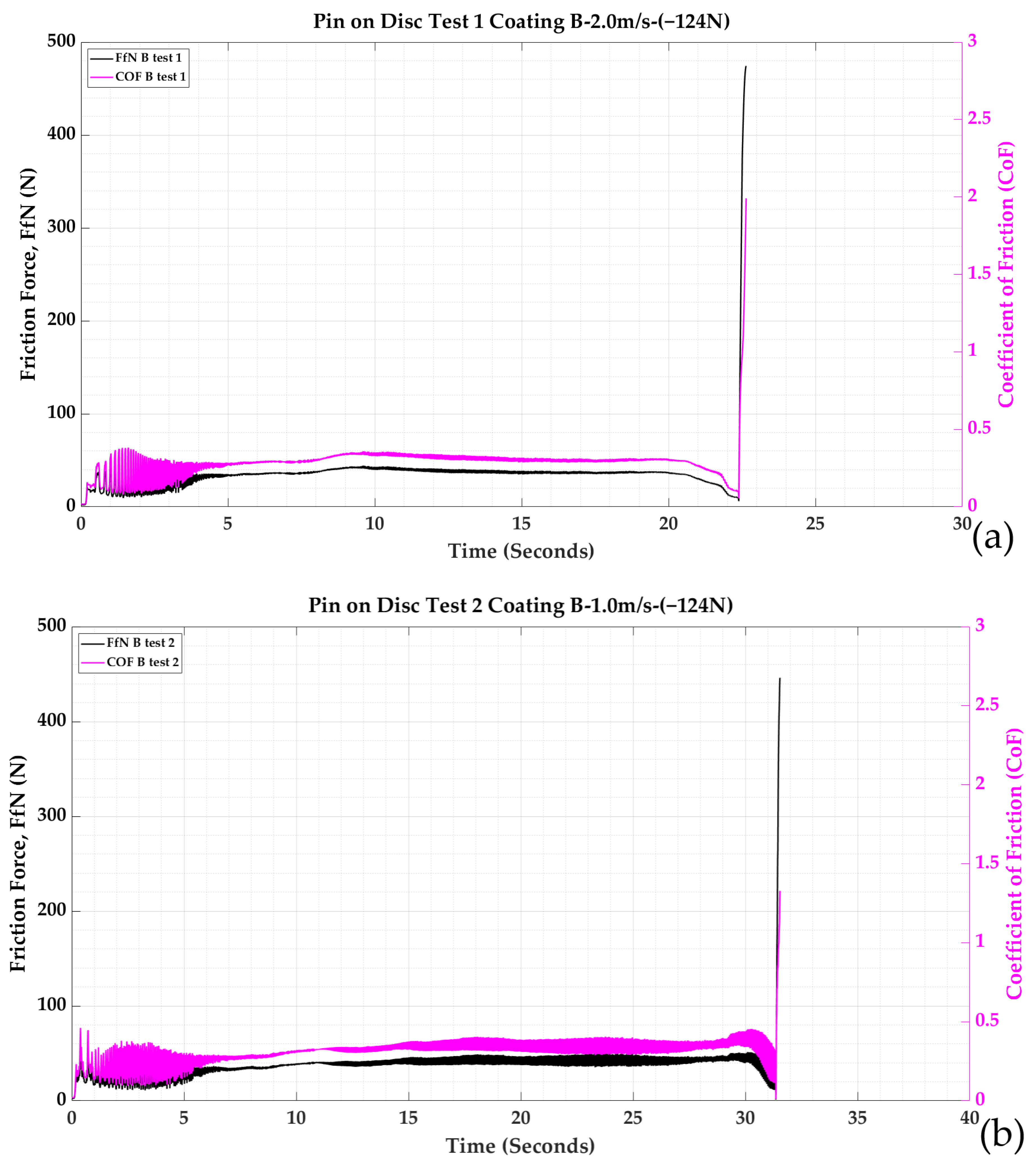
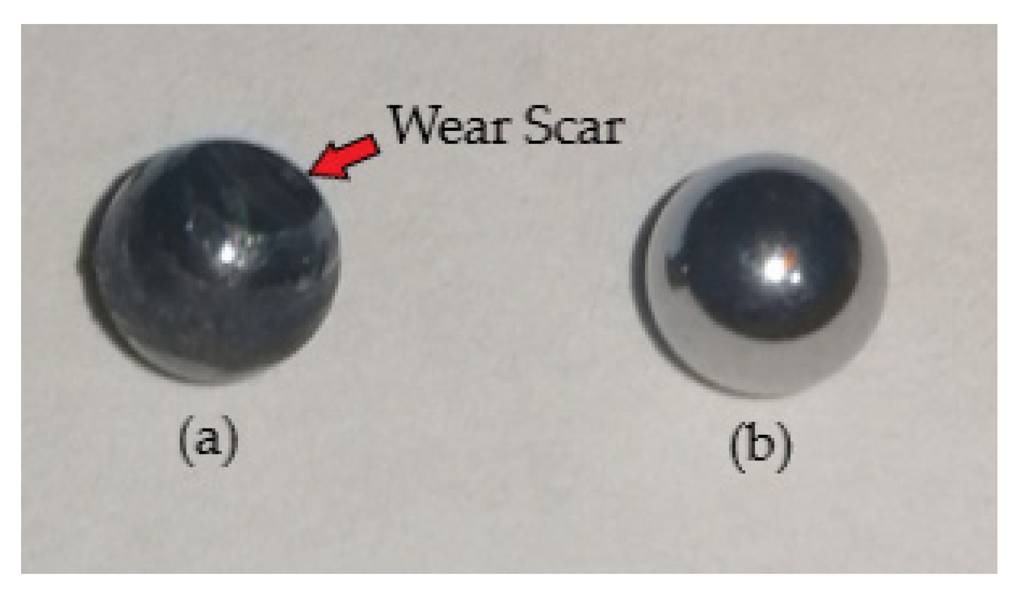
3.1. Pin-on-Disc Test Analysis and Discussion

The results of pin-on-disc testing for Coating A and Coating B in Test 1a and Test 2a are shown in in Figure 3, with Test 1b and 2b shown in Figure 4. From the Hertzian analysis, the applied loads that Coating B was subjected to were higher than the applied loads that Coating A was subjected to. This is because of the better resistance to deformation that is exhibited by the coating microstructure of Coating B when compared to the stability of Coating A.
The peaks in the coefficient of friction (CoF) and friction force (FfN) are presented in Figure 3a,b and Figure 4a,b. These peaks are an indication that the steel ball specimens have failed and that the coatings have also failed.
To reach the required 1000 m sliding distance (Table 2) stipulated in ASTM Standard Test Method G-99-17 [19], the tests would each need to last 496 s. As a result of the contact conditions, the two CVD coatings quickly degraded after about 22 s at the linear velocity of 2.0 m/s in Test 1a and Test 1b. For the first three seconds of Test 1a and Test 1b, the applied loads of 78 N and 124 N were respectively applied to the surface of the CVD-coated inserts. The insert support fixture was spun up to a linear velocity of 2.0 m/s for the first test. The test fixture was then spun up to a linear velocity of 2.0 m/s for the second test. The applied loads were applied by the actuator and measured by the load cell transducer at a sliding velocity of 2.0 m/s for Test 1a and Test 1b, which culminated in Coating A failing after 24.81 s (Figure 3). The calculated sliding distances and the times are shown in Table 2.
Once the fixture had reached a linear velocity of 2.0 m/s, the 4 mm diameter AISI 52100 steel ball counter specimen quickly succumbed to high frictional forces in the contact region and began to degrade and wear quickly. The friction coefficient for Coating A, as seen in Figure 5a, remained constant until the adhesion between the now heavily worn steel ball counter specimens (represented in Figure 5) resulted in delamination of Coating A (Regions 1 and 2 in Figure 6) and Coating A (Region 4 in Figure 7a) and Region 5 in Figure 7b). Once Coating A began to delaminate and the coefficient of friction increased sharply, Test 1a was stopped.
The primary reason for the failure of Coating A is likely due to the weak interfacial bonds being created between the interfacial layer of titanium nitride (TiN) and the SiAlON ceramic substrate. Although Test 1b for Coating B lasted a slightly shorter period of time at 22.64 s, Coating B was exposed to a higher applied load. The improved wear characteristics of Coating B when compared to Coating A are evident in Figure 6. The red boxes seen in Figure 6, Figure 7, Figure 8, Figure 9, Figure 10, Figure 11, Figure 12 and Figure 13 signify areas of for further interest.
Figure 7. SEM images of Coating A after pin-on-disc Test 1a: (a) ×1500 magnification, (b) ×3000 magnification.
Jmmp 07 00067 g007
Figure 8. SEM images of Coating B after pin-on-disc Test 1b: (a) ×50 magnification, (b) ×800 magnification.
Jmmp 07 00067 g008
Figure 9. SEM images of Coating B after pin-on-disc Test 1b: (a) ×1500 magnification, (b) ×3000 magnification.
Jmmp 07 00067 g009
Figure 10. SEM images of Coating A after pin-on-disc Test 2a: (a) ×50 magnification, (b) ×800 magnification.
Jmmp 07 00067 g010
Figure 11. SEM images of Coating A after pin-on-disc Test 2a: (a) ×1500 magnification, (b) ×3000 magnification.
Jmmp 07 00067 g011
Figure 12. SEM images of Coating B after pin-on-disc Test 2b: (a) ×50 magnification, (b) ×800 magnification.
Jmmp 07 00067 g012
Figure 13. SEM images of Coating B after pin-on-disc Test 2b: (a) ×1500 magnification, (b) ×3000 magnification.
Jmmp 07 00067 g013
Coating B had higher resistance to delamination (Regions 1 and 2 in Figure 8 and Regions 4 and 5 in Figure 9) than Coating A (seen in Regions 1 and 2 in Figure 6 and Region 5 in Figure 7b). The friction coefficient for Coating B fluctuated slightly, as seen in Figure 4a. The fluctuating friction forces leveled out until the adhesion between the now heavily worn steel ball counter specimen and Coating B became excessive, as shown in Figure 5.
The higher adhesion characteristics and the greater resistance to deformation and delamination of Coating B were likely attained due to high interfacial ionic/covalent bonds being created between the interfacial layer of amorphous α-Al2O3 and the SiAlON ceramic substrate.
The lower friction characteristics of the titanium nitride (TiN) microstructure can be attributed to the higher stability characteristics. Shoja et al. [13] concluded that α-Al2O3 coatings plastically deform on the rake face at different locations with different slip systems. The basal slip system is mostly activated during deformation, which is followed by the first and second prismatic slip systems.
This type of deformation correlated into a controlled and effective dispersion of the applied loads between the steel ball counter specimen and Coating B. The high stability characteristics and low coefficient of friction of the TiN outer layer, together with the higher stability and robustness of the amorphous α-Al2O3 interfacial layer of Coating B compared to Coating A, created a coating microstructure that was equipped to resist and distribute the high loads being applied.
M’Saoubi et al. [15] conclude that a textured α-Al2O3 microstructure that has a controlled crystal orientation has a high resistance to deformation, as can be seen in Figure 8 and Figure 9. The textured microstructure exhibits very high stability when subjected to high load forces at ambient temperatures.
For Test 2a and Test 2b (Figure 10, Figure 11, Figure 12 and Figure 13), linear velocity in the test fixture was reduced to 1.0 m/s when compared to the linear velocity of 2.0 m/s that was utilised in Test 1a and Test 1b for Coating A and Coating B.
The reduction in linear velocity was undertaken to investigate if this would have an impact on the sliding distance that could be attained before failure and the wear characteristics that had been evident in Test 1a and Test 1b for both Coating A and Coating B. The friction coefficient for Coating A, as seen in Figure 3b, remained near constant until the adhesion suddenly increased, which was represented by the now heavily worn steel ball counter specimen and the coating, as shown by Figure 5.
However, when the insert support fixture had reached a linear velocity of 1.0 m/s, the 4 mm diameter steel ball counter specimen began to degrade and wear as a result of the high forces in the contact region. The degradation of Coating A and the steel ball was slightly slower and resulted in Test 2a being stopped after a time of T = 35.56 s.
The friction coefficient, as seen in Figure 3b, remained near constant until the adhesion between the heavily worn steel ball counter specimen and Coating A (Regions 5 and 6 in Figure 11) resulted in delamination. Once Coating A began to delaminate and the coefficient of friction increased quickly (from 0.43 up to 2.7, as seen in Figure 3b), Test 2a was stopped. Coating A failed as result of weak interfacial bonds being created between the titanium nitride (TiN) interface layer and the SiAlON ceramic substrate.
What was apparent in both Test 1a and Test 2a for Coating A and Test 1a and Test 2a for Coating B was that the steel ball degraded quickly, which is evident in Figure 5. The degradation was due to thermomechanical wear of the steel ball counter specimen, which is evident in the formation of circular metallic wear tracks that were left on the insert rake face (Region 1 and 2 in Figure 12a).
The metallic wear track was a result of degradation and wear on the steel ball counter specimen (Figure 5), which in turn increased the contact area. Once the adhesion between the worn steel ball counter specimen and the outer layer of the Al2O3 was sufficient, the tensile stresses being induced into the coating microstructure in the contact region prompted the titanium nitride (TiN) interfacial layer to shear, which quickly resulted in coating delamination. For Test 2b with Coating B, the high stability of Coating B is evident in Figure 12 and Figure 13.
The lack of deformation in Coating B can be in seen in Regions 1 and 2 in Figure 12. What was clear from Test 1b and Test 2b was that the bilayer (Al2O3 + TiN) microstructure of Coating B resisted the compressive stress being induced into the coating microstructure. This resistance to fluctuating compressive stresses originated from high interfacial bonds being created in the Al2O3 coating/SiAlON ceramic substrate interface, which reduced the rate of deformation of the interface.
The high wear resistance and low friction of coefficient of titanium nitride (TiN) created a contact which suffered from less adhesion and, in turn, a lower level of fluctuating stresses, which led to coating failure. Test 2b for Coating B was stopped as a result of the steel ball failing due to significant thermomechanical wear.

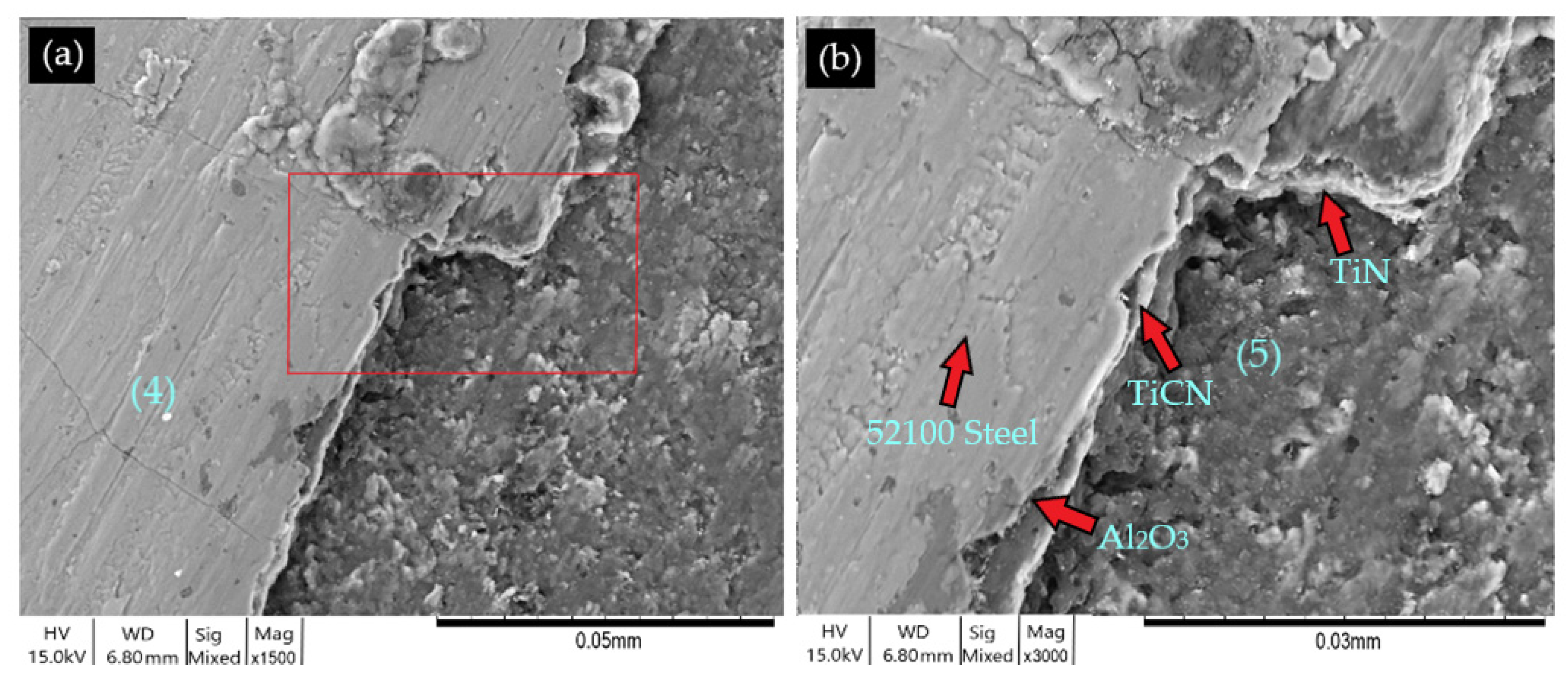
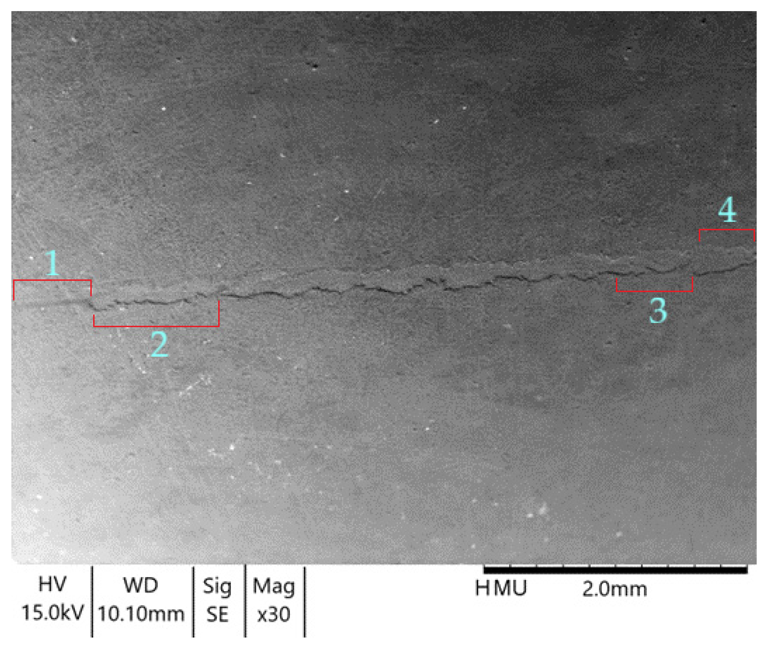
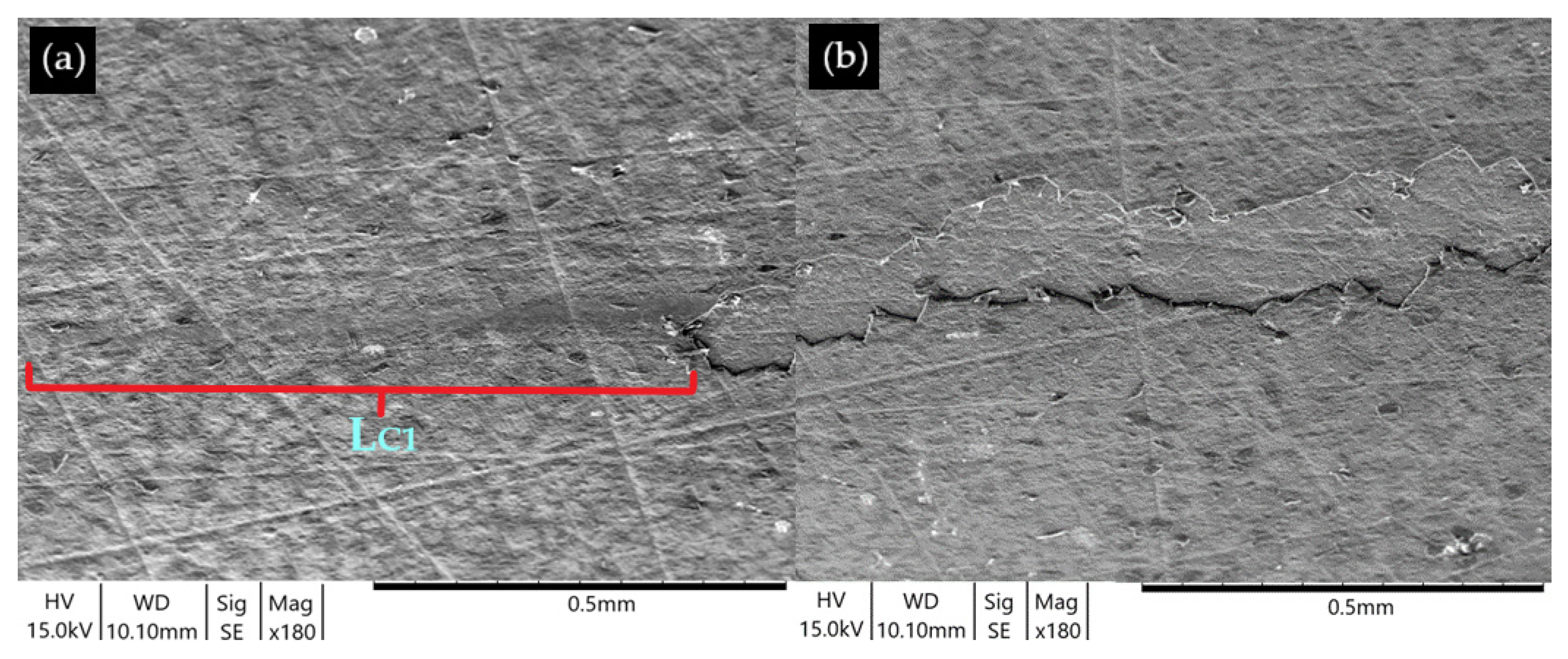
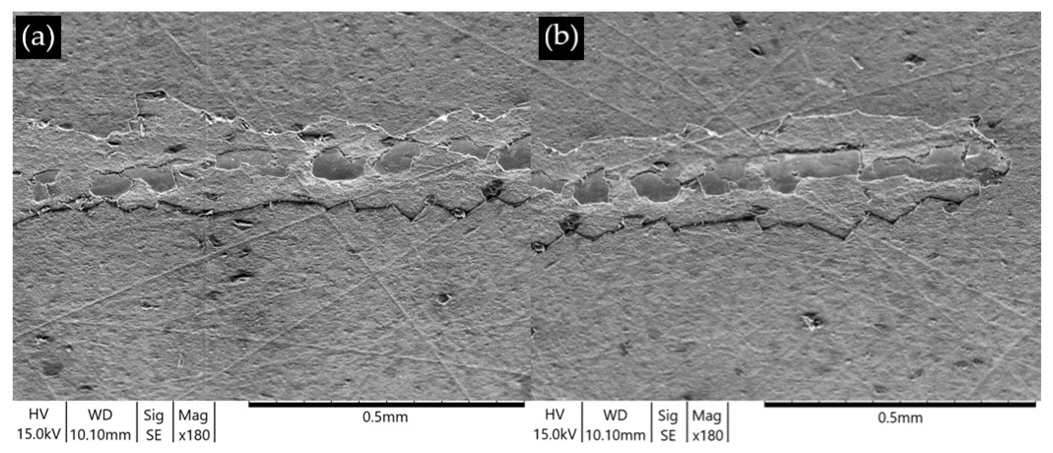
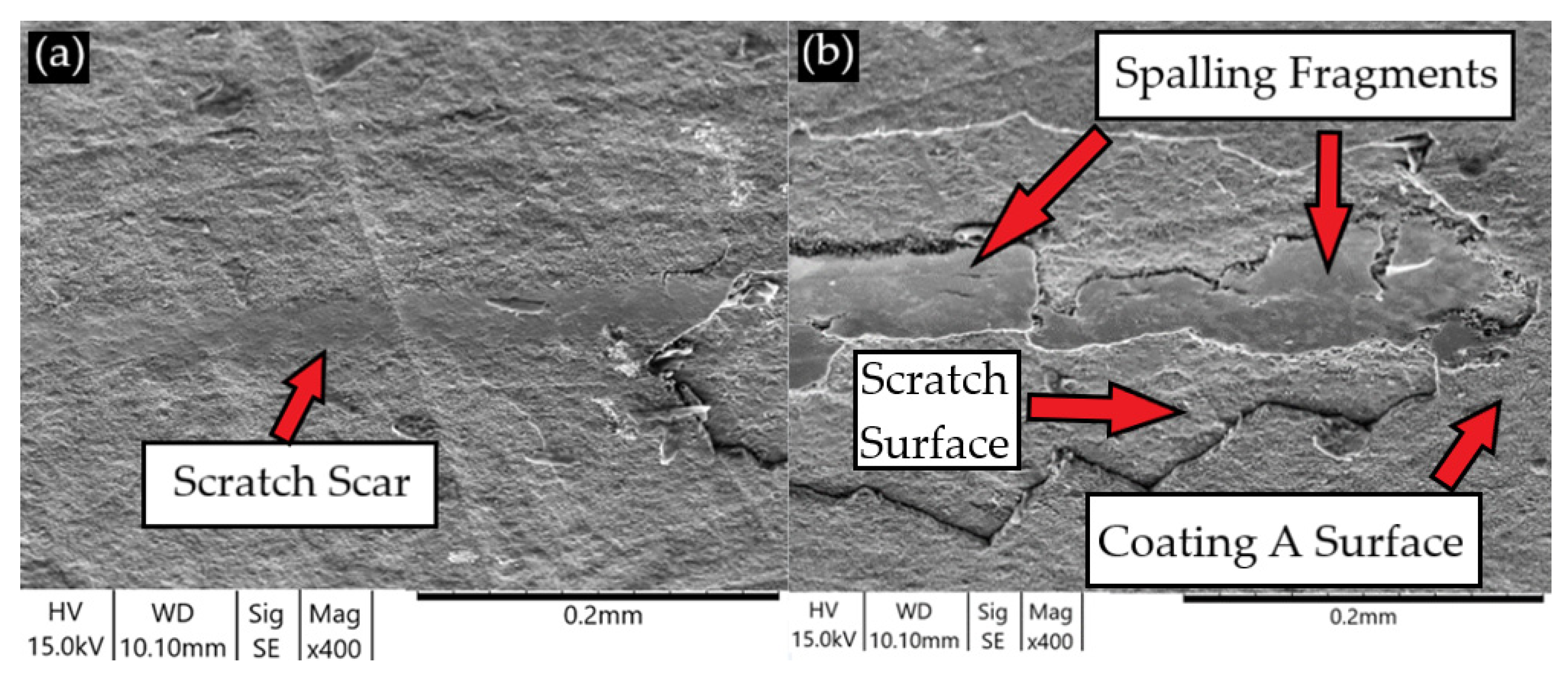
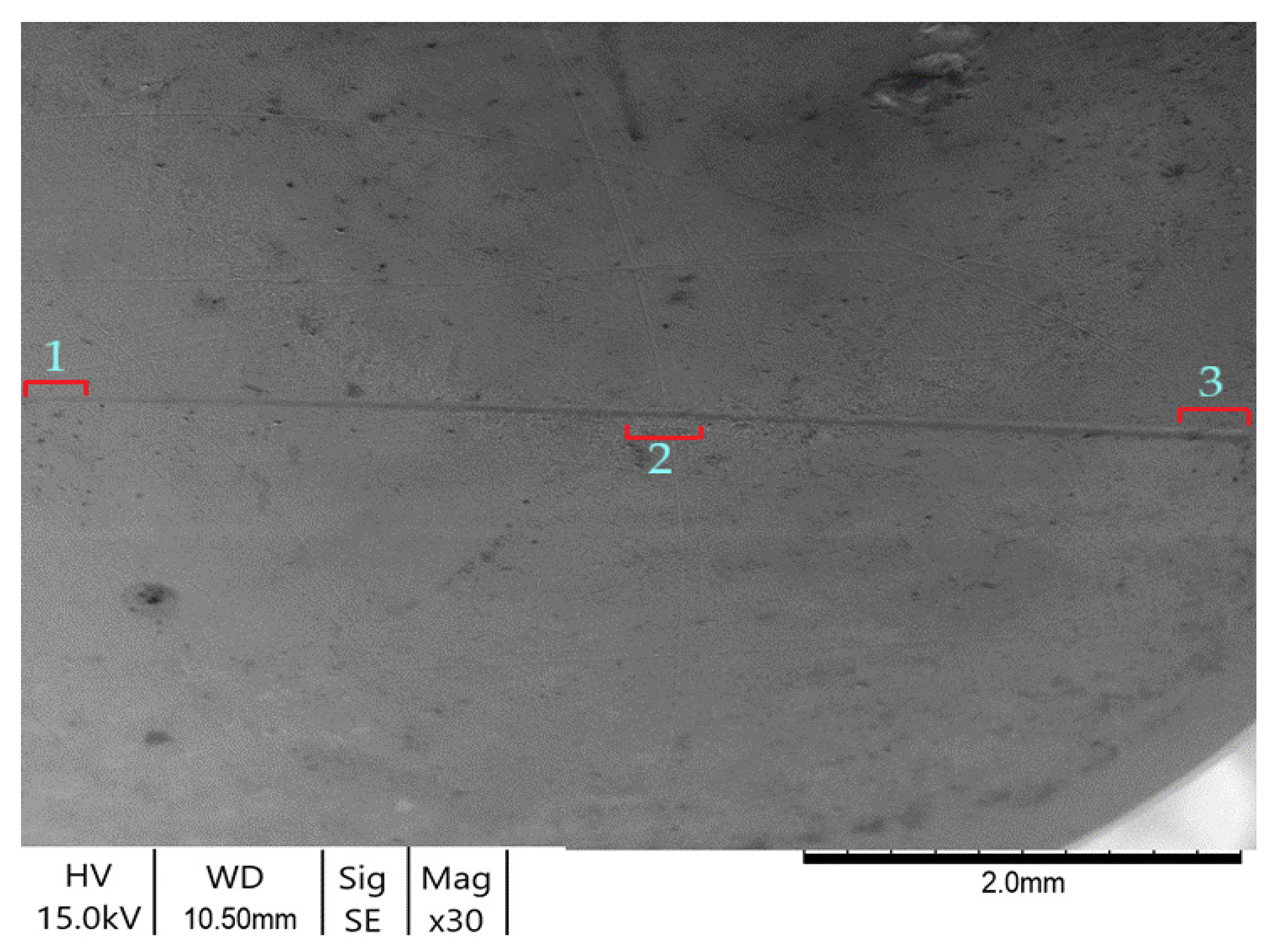
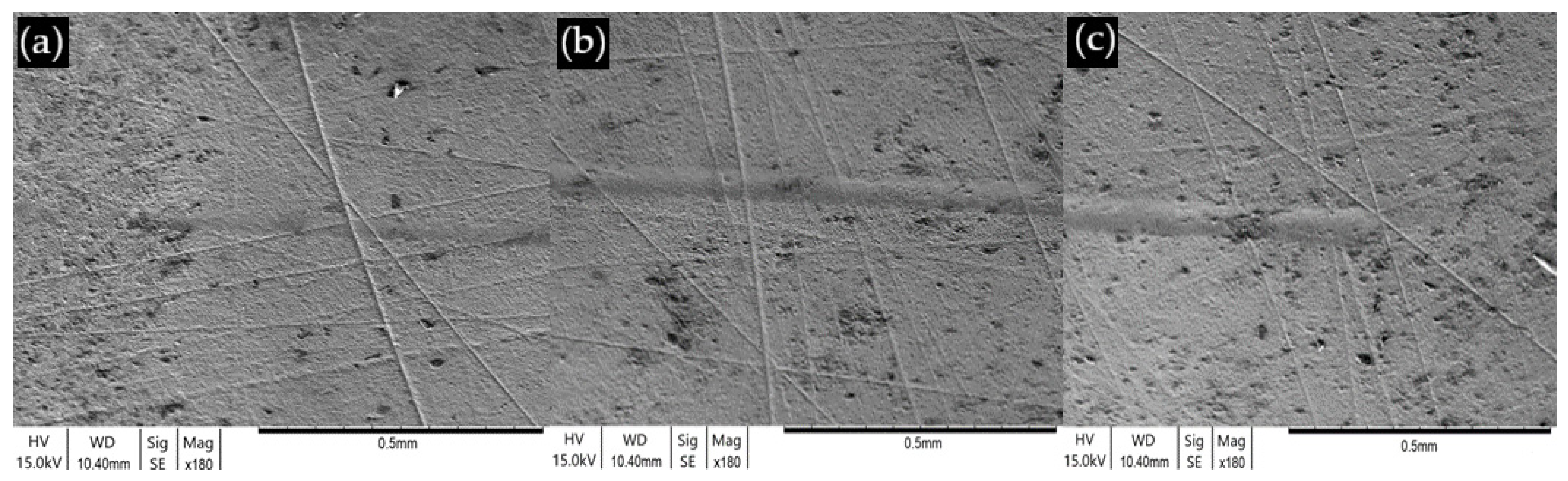
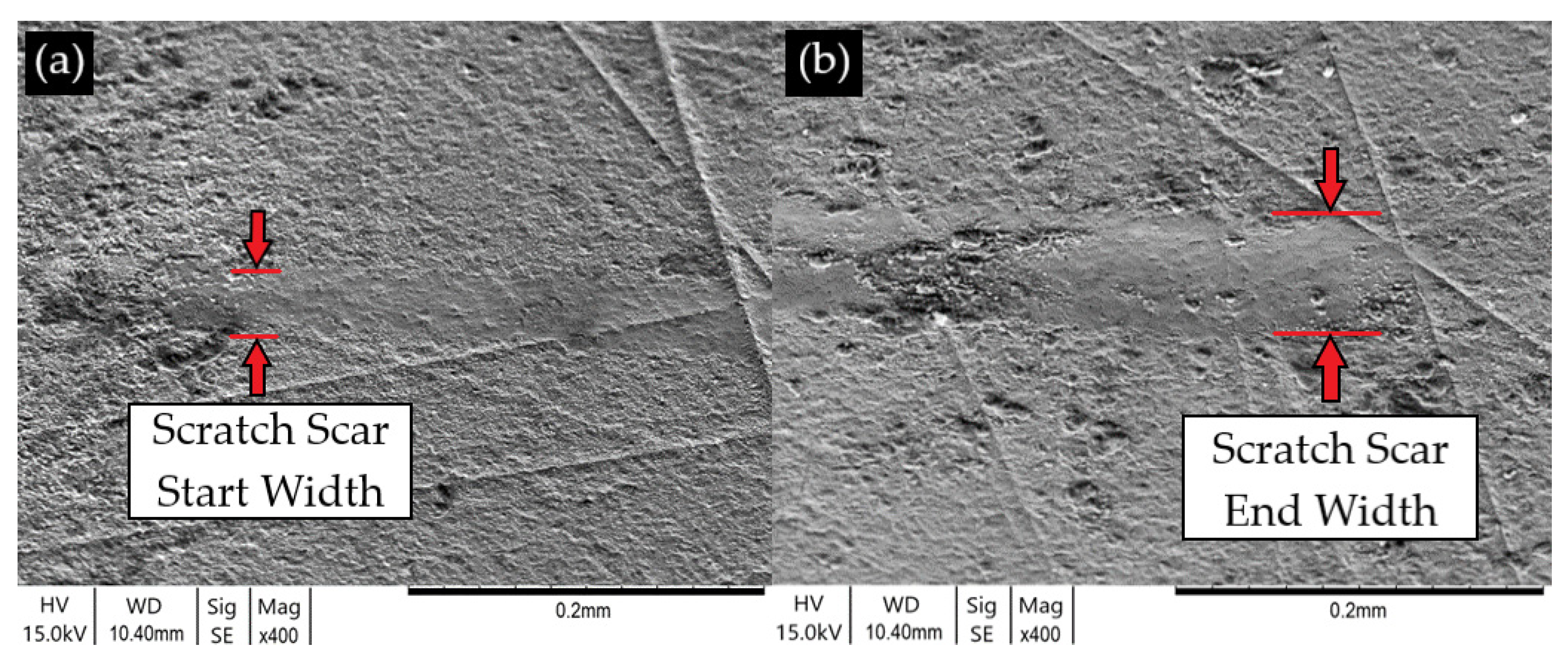
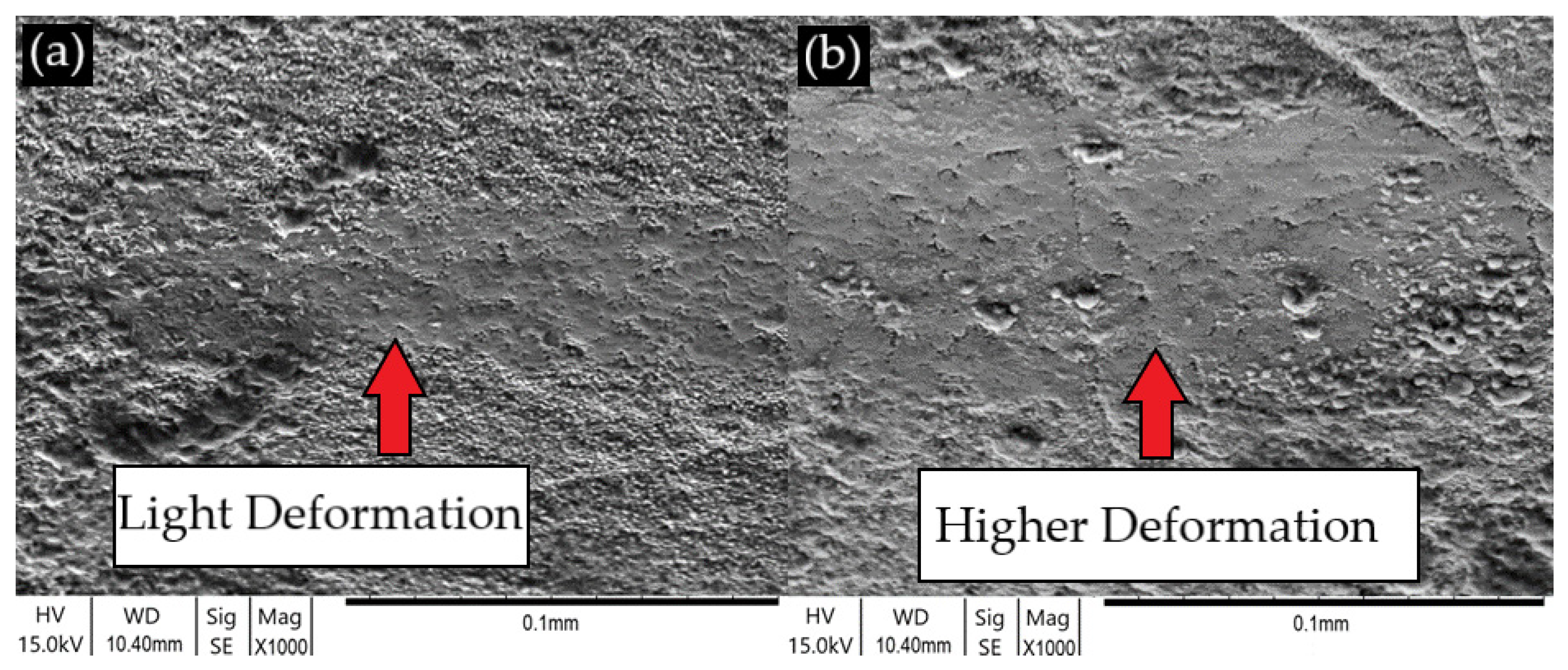
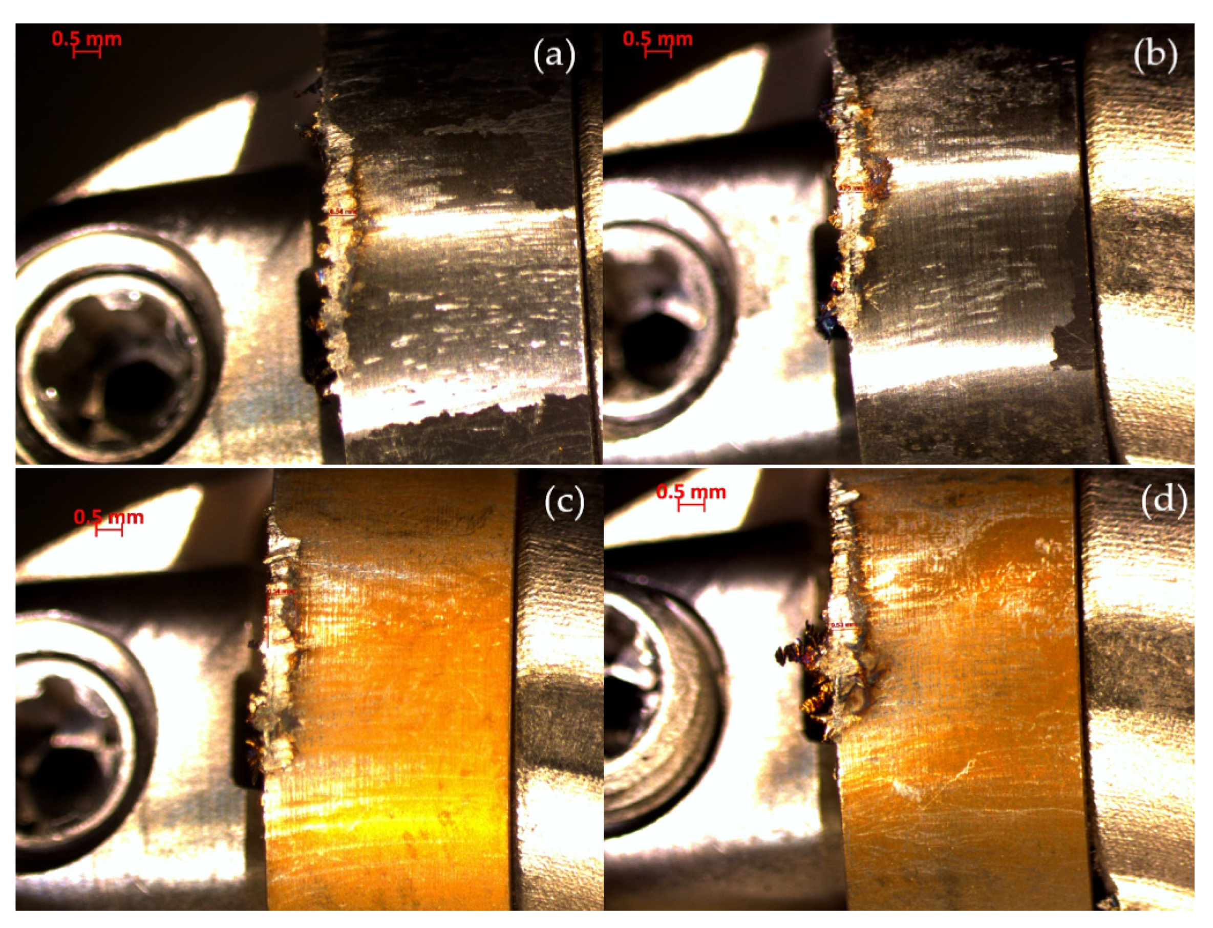
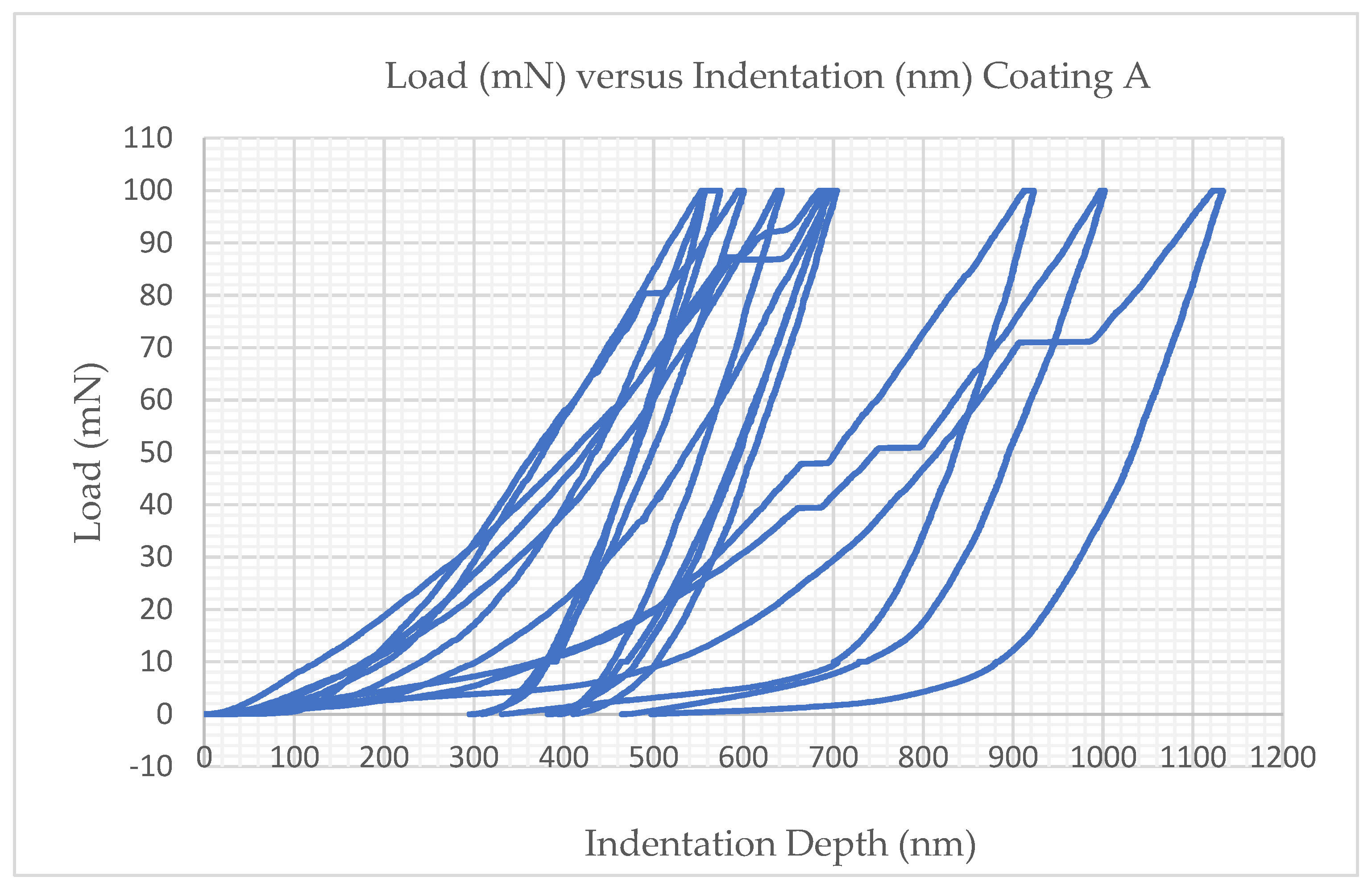
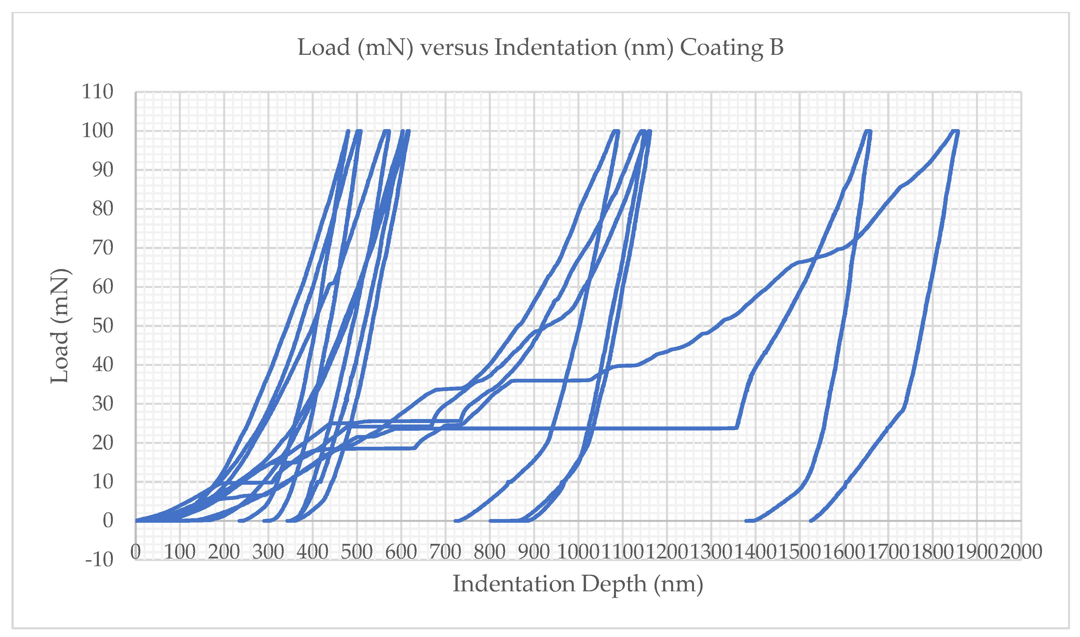
3.2. Scratch Testing Analysis and Discussion

Analysis of the two scratches was conducted in two parts. Firstly, a non-contact 3D profilometer (focus-variation type) was used. This analysis confirmed that Coating A had suffered from substantial amounts of wear and sudden fracture of the coating, which resulted in delamination, as seen in Figure 14a,c, due to an increased level of scratch force. Figure 14b,d indicate that Coating B had endured very little wear and no coating delamination. A scanning electron microscope was used to perform an examination of the two CVD-coated SiAlON ceramic milling inserts, and this visual SEM analysis is captured in Figure 15, Figure 16, Figure 17, Figure 18, Figure 19, Figure 20, Figure 21, Figure 22 and Figure 23.
It was observed that the amount of adhesion to the SiAlON ceramic substrate of CVD Coating A (TiN + TiCN + Al2O3) varied quite considerably when compared to the adhesion attained by Coating B (Al2O3 + TiN). The highly adherent properties that were exhibited by Coating B are due to the high-strength interfacial bonds that are created between the SiAlON ceramic substrate and the interfacial layer of amorphous α-Al2O3 during the CVD coating process. The high-temperature chemical vapour deposition process takes place in the region of 1050 °C, which is an ideal temperature for chemical reactions to take place to create the amorphous α-Al2O3 polymorphs.
The high temperatures establish the creation of high thermal interfacial bonding energies between the SiAlON ceramic substrate and the gaseous AICl3/H2/C02 vapour mixture of atoms. Previous work [26,36] concluded that, as vapour decomposes and begins to nucleate and bond with the SiAlON ceramic substrate, the amorphous α-Al2O3 polymorphs will begin to grow layer by layer to create an amorphous aluminium oxide coating.
Coating   A   L C 1 = [ 100 ( N / min ) { 1.057 ( mm ) 10 ( mm / min ) } ] + 0 = 10.57   N ± 0.001   N
Coating   B   L C 1 = [ 100 ( N / min ) { 9.89 ( mm ) 10 ( mm / min ) } ] + 0 = 99.01   N   ± 0.001   N
For both coatings, LC2 = LC1, which is due to Coating A catastrophically failing in the coating/substrate interface after a linear distance of 1.057 mm. The coating/substrate interface failure of Coating A resulted in complete delamination of the coating for the rest of the scratch. Coating B deformed but did not fail at any point along the entire scratch; therefore, LC2 = LC1.
Ruppi et al. [29], however, propose that when α-Al2O3 polymorph layers grow perpendicularly on the basal 0001 plane to the substrate as a result of layer growth, a highly textured, hexagonal, close-packed microstructure is formed, which in turn creates a highly thermodynamically stable coating. The textured aluminium oxide α-Al2O3 microstructure provides high stability and resistance to the fluctuating shear and tensile stresses, which prevents the creation of fracture cracks between the interfacial bonding layer and the SiAlON ceramic substrate.
It was the stability of the α-Al2O3 interfacial layer that provided the resistance to deformation that is evident in Figure 20 and Figure 23. During the Coating A and Coating B scratch tests, a diamond stylus was subjected to a linearly increasing load of 100 N/min whilst being drawn at a rate of 10 mm/min across the coated surface until the point of adhesion failure and critical load was reached. Typically, before a hard coating begins to fail, it will suffer from the formation of microcracks at the surface of the scratch. Therefore, determining the “lower critical load” LC1 is important for clarifying the minimum load value at which the cracks first begin to develop.
Another important value to determine is the “higher critical load” LC2, which determines when complete delamination of the coating begins. The images that are shown in Figure 15 and Figure 17a,b highlight the deformation of the scratch at different stages. The weak adhesive properties of Coating A are demonstrated in Figure 16a,b, Figure 17a,b, Figure 18a,b and Figure 19a,b.
The inadequate adhesion to the SiAlON ceramic substrate demonstrated by Coating A was due to the low-strength interfacial bonds that had been formed between the titanium nitride (TiN) interfacial bond layer and the SiAlON ceramic substrate. After 1 mm of linear travel at a load of 10.57 N ±   0.001   N , tensile and shear stresses culminated in a sudden total fracture of the coating. Therefore, LC1 = LC2 for Coating A, which was 10.57 N ±   0.001   N . The inability of Coating A to adequately distribute the linearly increasing tensile and shear stresses throughout the coating microstructure resulted in the delamination of Coating A from the SiAlON ceramic substrate. Characteristically, hard coatings deteriorate from small cracks prior to failure, though here, Coating A failed catastrophically as result of brittle and weak interfacial layers, which in turn initiated the delamination of the rest of the coating as load was increased.
As the coating load increased, the spalling effects increased, and this is evident in Figure 18b. The principal cause for the abrupt failure of Coating A can be credited to the low-strength interatomic bonds being initiated between the isomorphic phases of titanium nitride (TiN) (lattice structure) in which metallic bonds occur.
These metallic bonds do not have the same capability to share valance electrons with the SiAlON covalent microstructure on an interatomic level as ionic bonds of Al2O3 have. The metallic covalent interactions between TiN and SiAlON ceramic atoms resulted in the creation of low-strength energy sites for nucleation, which in turn initiated the creation of low-strength interatomic bonds between the covalent microstructure of the silicon aluminium oxynitride (SiAlON) ceramic. Hence, once the TiN and the SiAlON ceramic interfacial bonds were exposed to adequate fluctuating shear and tensile stresses, interfacial cracks started to propagate and were thus the root cause of Coating A catastrophically failing after travelling 1 mm.
The image in Figure 20 highlights the deformation of the scratch at different stages. Figure 21 and Figure 22 illustrate the lack of coating deformation and subsequent delamination. There is no noticeable cracking compared to the level of wear that can be viewed in Figure 15 and Figure 19 with Coating A.
Figure 21a–c, Figure 22a,b and Figure 23a,b highlight the lack of physical degradation of the coating, which suggests that the interface that was created between the α-Al2O3 and the SiAlON ceramic substrate formed high-strength interatomic bonds. Aluminium oxide (α-Al2O3) ionic bonds have the capability to share valance electrons with the SiAlON ceramic covalent microstructure. This resulted in electronegativity interactions between Al2O3 and SiAlON ceramic atoms, which initiates high-energy sites for the nucleation of the α-Al2O3 interfacial layer atoms onto the surface of the SiAlON ceramic substrate. High interatomic bonds were then formed with the covalent microstructure of the silicon aluminium oxynitride (SiAlON) ceramic.
Furthermore, the tribological interaction of the diamond stylus between Coating A and B was different. As the friction co-efficient between the aluminium oxide (α-Al2O3) outer layer of Coating A was slightly higher than the titanium nitride (TiN) outer layer of Coating B, this particular characteristic would have had an effect on the sliding contact stresses, which were transmitted through the stylus tip into the surface of the coating.
Nonetheless, Coating B succeeded in withstanding the fluctuating shear and tensile stresses, which were transmitted through the stylus up to a maximum load of 100 N. Therefore, the LC1 value for Coating B was >100 N, and, since there had not been any deformation or complete failure in Coating B, LC1 = LC2; thus, the higher critical load, LC2, is >100 N. The lack of deformation for Coating B is visually represented by the width of the wear scar in Figure 22a,b. As a result of Coating B exhibiting superior resistance to deformation, and due to the complete lack of delamination, it is suggested that amorphous α-Al2O3 should be utilised in this type of coating and for future coating applications.

3.3. Comparing Tribological Analysis with Machining Trial Analysis

For comparison, the images seen in Figure 24 show SiAlON milling inserts that were CVD-coated with Coating A and Coating B. These inserts came from the same batch that was used in the experimental tests for pin-on-disc and scratch testing.
These inserts were used in a previously completed machining trial that utilised face milling operations. The Coating A and Coating B RNGN SiAlON milling inserts were used to machine precipitation-hardened Inconel 718 specimens with 1 mm depths of cut and three-axis machining toolpaths.
The typical cutting speed for machining Inconel 718 with SiAlON milling inserts varies from 500–1000 m/min, as stated in previous studies [3,4,7].
Comparing the images of Coating A in Figure 24a,b to Figure 8a, Figure 14c, Figure 15 and Figure 16a,b, there is good correlation between coating failure, coating removal and delamination similarities and the results of pin-on-disc and scratch testing for Coating A.
The same similarities and correlations are also evident for Coating B when comparing Figure 24c,d to Figure 8a, Figure 14d, Figure 21a–c, Figure 22a,b and Figure 23a,b in terms of coating removal, with Coating B exhibiting high resistance to deformation and delamination.

4. Conclusions

In this study, the overall goal was to understand the structure and resulting tribological properties of two CVD coatings that were deposited on to SiAlON substrates. From the testing and wear analysis conducted to ascertain the characteristics of two CVD coatings, the following conclusions can be drawn:
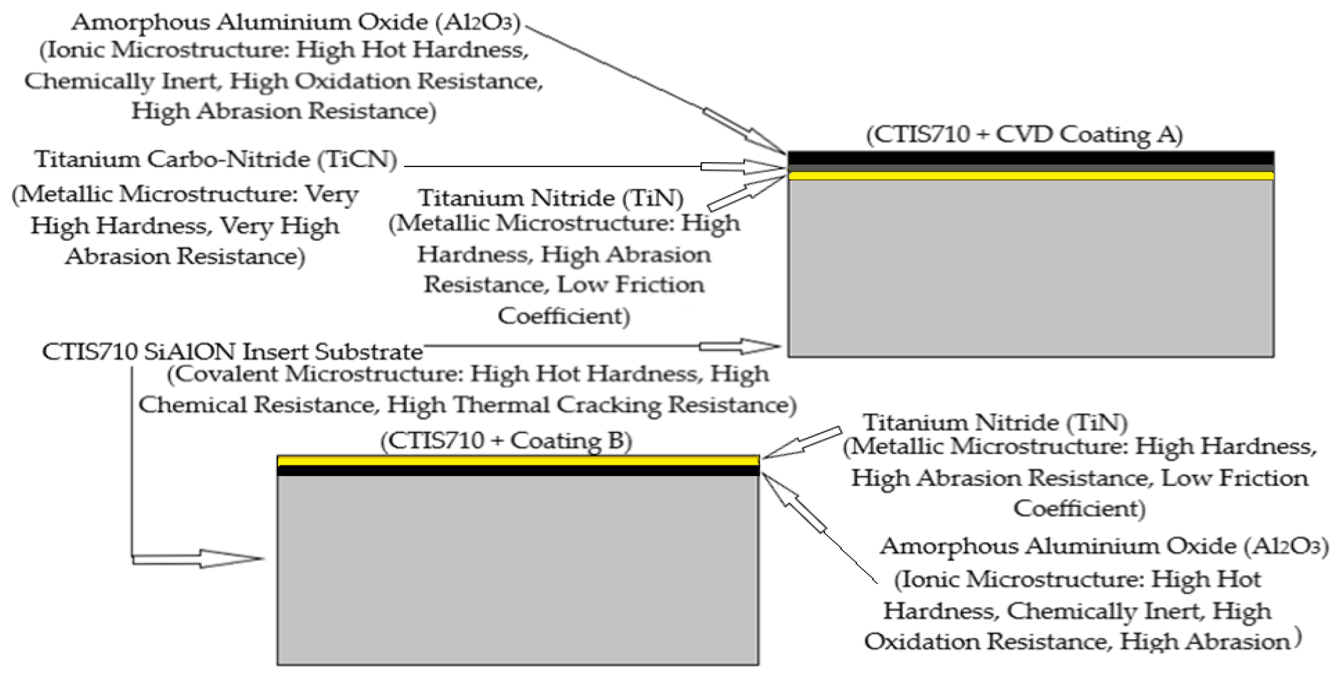
  • Amorphous α-Al2O3 has very high stability as an interfacial layer coating and demonstrated very high resistance to deformation when subjected to high tensile and shear stresses. When amorphous α-Al2O3 is deposited onto coating materials such as TiN and TiCN, the high stability is effectively lost due to dependence on metallic coating microstructures, which lack sufficient structural stability when subjected to alternating shear and tensile stresses. Therefore, multilayered coating systems such as TiN + TiCN + Al2O3 should be avoided for this type of cutting tool application.
  • TiN as a coating material demonstrated a series of mechanical and tribological characteristics. Favourable characteristics included decreased frictional interactions between the 52100 steel balls in the pin-on-disc tests and the diamond stylus in the scratch tests. TiN also demonstrated very high resistance to wear and abrasion. However, TiN also exhibited low stability in the interfacial layer of Coating A. This created a coating microstructure that is not able to resist and distribute the high compressive forces being applied in applications such as this.
  • Coating A (TiN + TiCN + Al2O3) exhibited significantly less adhesion to the SiAlON ceramic substrate than Coating B. This is due to low interfacial metallic /covalent bonds being created between the interfacial layer of amorphous TiN and the SiAlON ceramic substrate.
  • Coating B (Al2O3 + TiN) was more effectively bonded with the SiAlON ceramic substrate than Coating A. This is due to high interfacial ionic/covalent bonds being established between the interfacial layer of amorphous α-Al2O3 and the SiAlON ceramic substrate.

Author Contributions

Conceptualization, L.O. and T.S.; methodology, L.O.; software, L.O.; validation, L.O., I.C. and T.S.; formal analysis, L.O.; investigation, L.O. and T.S.; resources, T.S.; data curation, L.O.; writing—original draft preparation, L.O.; writing—review and editing, T.S.; visualization, L.O.; supervision, I.C. and T.S.; project administration, L.O.; funding acquisition, L.O. All authors have read and agreed to the published version of the manuscript.

Funding

The authors would like to thank the Engineering and Physical Sciences Research Council (UK) (EP/L016257/1) and the University of Sheffield’s Advanced Manufacturing Research Centre (AMRC) for the kind sponsorship of this work. We wish to acknowledge the support of the Sir Henry Royce Institute for Advanced Materials provided to L.O. through the Student Equipment Access Scheme and enabling access to facilities at the University of Manchester; EPSRC Grant Number EP/R00661X/1.

Data Availability Statement

Not applicable.

Acknowledgments

The authors would also like to thank CERATIZIT UK & Ireland Ltd. for supplying the ceramic inserts, insert holders and spindles for this research project.

Conflicts of Interest

The authors declare no conflict of interest.

Appendix A

Figure A1. Nanoindentation test results for Coating A.
Jmmp 07 00067 g0a1
Figure A2. Nanoindentation test results for Coating B.
Jmmp 07 00067 g0a2

References

  1. Konyashin, I.Y. Chemical Vapor Deposition of Thin Coatings onto A1203 Indexable Cutting Inserts. Surf. Coat. Technol. 1995, 85, 131–137. [Google Scholar] [CrossRef]
  2. López de Lacalle, L.N.; Fernández Valdivielso, A.; Amigo, F.J.; Sastoque, L. Milling with Ceramic Inserts of Austempered Ductile Iron (ADI): Process Conditions and Performance. Int. J. Adv. Manuf. Technol. 2020, 110, 899–907. [Google Scholar] [CrossRef] [PubMed]
  3. Molaiekiya, F.; Stolf, P.; Paiva, J.M.; Bose, B.; Goldsmith, J.; Gey, C.; Engin, S.; Fox-Rabinovich, G.; Veldhuis, S.C. Influence of Process Parameters on the Cutting Performance of SiAlON Ceramic Tools during High-Speed Dry Face Milling of Hardened Inconel 718. Int. J. Adv. Manuf. Technol. 2019, 105, 1083–1098. [Google Scholar] [CrossRef]
  4. Tian, X.; Zhao, J.; Dong, Y.; Zhu, N.; Zhao, J.; Li, A. A Comparison between Whisker-Reinforced Alumina and SiAlON Ceramic Tools in High-Speed Face Milling of Inconel 718. Proc. Inst. Mech. Eng. Part B J. Eng. Manuf. 2014, 228, 845–857. [Google Scholar] [CrossRef]
  5. Ma, Z.; Xu, X.; Huang, X.; Ming, W.; An, Q.; Chen, M. Cutting Performance and Tool Wear of SiAlON and TiC-Whisker-Reinforced Si3N4 Ceramic Tools in Side Milling Inconel 718. Ceram. Int. 2022, 48, 3096–3108. [Google Scholar] [CrossRef]
  6. Guo, F.; Yin, Z.; Hong, D.; Yu, K.; Yuan, J. Cutting Performance of a New Spark Plasma Sintered SiAlON Ceramic Tool for High-Speed Milling of Inconel 718. Int. J. Adv. Manuf. Technol. 2022, 119, 7327–7338. [Google Scholar] [CrossRef]
  7. Yıldırım, Ç.V.; Kıvak, T.; Erzincanlı, F. Tool Wear and Surface Roughness Analysis in Milling with Ceramic Tools of Waspaloy: A Comparison of Machining Performance with Different Cooling Methods. J. Braz. Soc. Mech. Sci. Eng. 2019, 41, 83. [Google Scholar] [CrossRef]
  8. Seleznev, A.; Pinargote, N.W.S.; Smirnov, A. Ceramic Cutting Materials and Tools Suitable for Machining High-Temperature Nickel-Based Alloys: A Review. Metals 2021, 11, 1385. [Google Scholar] [CrossRef]
  9. Porat, R. CVD coating of ceramic layers on ceramic cutting tool materials. J. Phys. IV 1991, 2, C2-549–C2-556. [Google Scholar] [CrossRef] [Green Version]
  10. Vereschaka, A.A.; Grigoriev, S.N.; Volosova, M.A.; Batako, A.; Vereschaka, A.S.; Sitnikov, N.N.; Seleznev, A.E. Nano-Scale Multi-Layered Coatings for Improved Efficiency of Ceramic Cutting Tools. Int. J. Adv. Manuf. Technol. 2017, 90, 27–43. [Google Scholar] [CrossRef]
  11. Sousa, V.F.C.; Silva, F.J.G. Recent Advances on Coated Milling Tool Technology—A Comprehensive Review. Coatings 2020, 10, 235. [Google Scholar] [CrossRef] [Green Version]
  12. Vereschaka, A.A.; Volosova, M.A.; Krapostin, A.A.; Batako, A.; Seleznev, A.E. Increased Operating Properties of Cutting Ceramics by Application of Nanostructured Multilayer Wear-Resistant Coating. J. Nano Res. 2017, 50, 90–104. [Google Scholar] [CrossRef]
  13. Mikuła, J.; Pakuła, D.; Żukowska, L.; Gołombek, K.; Kříž, A. Wear Resistance of (Ti,Al)N Metallic Coatings for Extremal Working Conditions. Coatings 2021, 11, 157. [Google Scholar] [CrossRef]
  14. You, Q.; Xiong, J.; Guo, Z.; Liu, J.; Yang, T.; Qin, C. Microstructure and Properties of CVD Coated Ti(C, N)-Based Cermets with Varying WC Additions. Int. J. Refract. Met. Hard Mater. 2019, 81, 299–306. [Google Scholar] [CrossRef]
  15. Liu, W.; Chu, Q.; He, R.; Huang, M.; Wu, H.; Jiang, Q.; Chen, J.; Deng, X.; Wu, S. Preparation and Properties of TiAlN Coatings on Silicon Nitride Ceramic Cutting Tools. Ceram. Int. 2018, 44, 2209–2215. [Google Scholar] [CrossRef]
  16. Liu, J.; Ma, C.; Tu, G.; Long, Y. Cutting Performance and Wear Mechanism of Sialon Ceramic Cutting Inserts with TiCN Coating. Surf. Coat. Technol. 2016, 307, 146–150. [Google Scholar] [CrossRef]
  17. Grigoriev, S.N.; Volosova, M.A.; Fedorov, S.V.; Okunkova, A.A.; Pivkin, P.M.; Peretyagin, P.Y.; Ershov, A. Development of DLC-Coated Solid SiAlON/TiN Ceramic End Mills for Nickel Alloy Machining: Problems and Prospects. Coatings 2021, 11, 532. [Google Scholar] [CrossRef]
  18. Pereira, O.; Celaya, A.; Urbikaín, G.; Rodríguez, A.; Fernández-Valdivielso, A.; de Lacalle, L.N.L. CO2 Cryogenic Milling of Inconel 718: Cutting Forces and Tool Wear. J. Mater. Res. Technol. 2020, 9, 8459–8468. [Google Scholar] [CrossRef]
  19. Fernández-Valdivielso, A.; López de Lacalle, L.; Urbikain, G.; Rodriguez, A. Detecting the Key Geometrical Features and Grades of Carbide Inserts for the Turning of Nickel-Based Alloys Concerning Surface Integrity. Proc. Inst. Mech. Eng. Part C J. Mech. Eng. Sci. 2016, 230, 3725–3742. [Google Scholar] [CrossRef]
  20. Ruppi, S. Influence of Process Conditions on the Growth and Texture of CVD Alpha-Alumina. Coatings 2020, 10, 158. [Google Scholar] [CrossRef] [Green Version]
  21. Konstantiniuk, F.; Tkadletz, M.; Kainz, C.; Czettl, C. Nina Schalk a Mechanical Properties of Single and Polycrystalline α-Al2O3 Coatings Grown by Chemical Vapor Deposition. Surf. Coat. Technol. 2021, 410, 126959. [Google Scholar] [CrossRef]
  22. Ding, J.; Meng, Y.; Wen, S. Mechanical Properties and Fracture Toughness of Multilayer Hard Coatings Using Nanoindentation. Thin Solid Films 2000, 371, 178–182. [Google Scholar] [CrossRef]
  23. Hochauer, D.; Mitterer, C.; Penoy, M.; Puchner, S.; Michotte, C.; Martinz, H.P.; Hutter, H.; Kathrein, M. Carbon Doped α-Al2O3 Coatings Grown by Chemical Vapor Deposition. Surf. Coat. Technol. 2012, 206, 4771–4777. [Google Scholar] [CrossRef]
  24. Zhu, B.; Zhu, Y.; Li, X.; Zhao, F. Effect of Ceramic Bonding Phases on the Thermo-Mechanical Properties of Al2O3—C Refractories. Ceram. Int. 2013, 39, 6069–6076. [Google Scholar] [CrossRef]
  25. Shoja, S.; Mortazavi, N.; Lindahl, E.; Norgren, S.; Bäcke, O.; Halvarsson, M. Microstructure Investigation of Textured CVD Alumina Coatings. Int. J. Refract. Met. Hard Mater. 2020, 87, 105125. [Google Scholar] [CrossRef]
  26. Vuorinen, S.; Karlsson, L. Phase Transformation in Chemically Vapour-Deposited κ-Alumina. Thin Solid Films 1992, 214, 132–143. [Google Scholar] [CrossRef]
  27. Ruppi, S.; Larsson, A.; Flink, A. Nanoindentation Hardness, Texture and Microstructure of α-Al2O3 and κ-Al2O3 Coatings. Thin Solid Films 2008, 516, 5959–5966. [Google Scholar] [CrossRef]
  28. Shoja, S.; Alm, O.; Norgren, S.; Andrén, H.-O.; Halvarsson, M. Calculated and Experimental Schmid Factors for Chip Flow Deformation of Textured CVD α-Alumina Coatings. Surf. Coat. Technol. 2021, 412, 126991. [Google Scholar] [CrossRef]
  29. Ruppi, S. Enhanced Performance of α-Al2O3 Coatings by Control of Crystal Orientation. Surf. Coat. Technol. 2008, 202, 4257–4269. [Google Scholar] [CrossRef]
  30. M’Saoubi, R.; Alm, O.; Andersson, J.M.; Engström, H.; Larsson, T.; Johansson-Jõesaar, M.P.; Schwind, M. Microstructure and Wear Mechanisms of Texture-Controlled CVD α-Al2O3 Coatings. Wear 2017, 376, 1766–1778. [Google Scholar] [CrossRef]
  31. de Figueiredo, M.R.; Abad, M.D.; Harris, A.J.; Czettl, C.; Mitterer, C.; Hosemann, P. Nanoindentation of Chemical-Vapor Deposited Al2O3 Hard Coatings at Elevated Temperatures. Thin Solid Films 2015, 578, 20–24. [Google Scholar] [CrossRef]
  32. Riedl, A.; Schalk, N.; Czettl, C.; Sartory, B.; Mitterer, C. Tribological Properties of Al2O3 Hard Coatings Modified by Mechanical Blasting and Polishing Post-Treatment. Wear 2012, 289, 9–16. [Google Scholar] [CrossRef]
  33. Tkadletz, M.; Schalk, N.; Daniel, R.; Keckes, J.; Czettl, C.; Mitterer, C. Advanced Characterization Methods for Wear Resistant Hard Coatings: A Review on Recent Progress. Surf. Coat. Technol. 2016, 285, 31–46. [Google Scholar] [CrossRef]
  34. Zhang, C.; Lu, J.; Zhang, F.; Butt, S.I. Identification of a New Friction Model at Tool-Chip Interface in Dry Orthogonal Cutting. Int. J. Adv. Manuf. Technol. 2017, 89, 921–932. [Google Scholar] [CrossRef]
  35. ASTM G99-17; Standard Test Method for Wear Testing with a Pin-on-Disk Apparatus. ASTM International: West Conshohocken, PA, USA, 2017. [CrossRef]
  36. Fredriksson, E.; Carlsson, J.-O. Phase Transformation during CVD of Aluminium Oxide. J. Phys. Colloq. 1989, 50, C5-391–C5-399. [Google Scholar] [CrossRef]
Figure 1. Typical inserts before use (a) CTIS710 SiAlON ceramic + Type A coating—CVD 6 µm thick TiN-TiCN-Al2O3 coating with α-Al2O3 (black colour); (b) CTIS710 SiAlON ceramic + Type B coating—3–4 µm thick α- Al2O3–TiN CVD coating optimised for SiAlON ceramics (yellow colour).
Jmmp 07 00067 g001
Figure 2. Cross-sectional view of the coating system’s microstructure and its mechanical characteristics.
Jmmp 07 00067 g002
Figure 3. Friction coefficient plot vs. time (seconds) vs. friction force (N): (a) Test 1a and (b) Test 2a for Coating A.
Jmmp 07 00067 g003
Figure 4. Friction coefficient plot vs. time (seconds) vs. friction force (N): (a) Test 1b and (b) Test 2b for Coating B.
Jmmp 07 00067 g004
Figure 5. (a) Worn 4 mm diameter 52100 steel ball that typically represents pin-on-disc Test 1a, 1b, 2a and 2b for Coating A and Coating B; (b) unused 4 mm diameter 52100 steel ball.
Jmmp 07 00067 g005
Figure 6. SEM images of Coating A after pin-on-disc Test 1a: (a) ×50 magnification, (b) ×800 magnification.
Jmmp 07 00067 g006
Figure 14. Non-contact 3D profilometer (focus—variation type) scan of (a,c) the Coating A scratch and (b,d) the Coating B scratch.
Jmmp 07 00067 g014
Figure 15. Coating A scratch positions 1, 2, 3 and 4 at ×30 Mag.
Jmmp 07 00067 g015
Figure 16. (a) Coating A scratch position 1 (initial scratch Lc1) and (b) Coating A scratch position 2 coating fractures and delamination positions at ×180 magnification.
Jmmp 07 00067 g016
Figure 17. (a) Coating A scratch position 3 (continued delamination and spalling) and (b) Coating A scratch position 4 (end of the scratch SEM) at ×180 magnification.
Jmmp 07 00067 g017
Figure 18. (a) Coating A scratch position 1 (initial scratch Lc1) and (b) Coating A scratch position 4 (end of the scratch SEM) at ×400 magnification.
Jmmp 07 00067 g018
Figure 19. (a) Coating A scratch position 1 (initial scratch Lc1) at ×1000 magnification and (b) Coating A scratch position 1 (initial scratch Lc1) at ×1500 magnification.
Jmmp 07 00067 g019
Figure 20. Coating B scratch positions 1, 2 and 3 at ×30 magnification.
Jmmp 07 00067 g020
Figure 21. (a) Coating B scratch position 1, (b) Coating B scratch position 2 and (c) Coating B scratch position 3 at ×180 magnification.
Jmmp 07 00067 g021
Figure 22. (a) Coating B scratch position 1 and (b) Coating B scratch position 3 at ×400 magnification.
Jmmp 07 00067 g022
Figure 23. (a) Coating B scratch position 1 and (b) Coating B scratch position 3 at ×1000 magnification.
Jmmp 07 00067 g023
Figure 24. Coating A RNGN insert test at (a) 700 m/min and (b) 800 m/min. Coating B RNGN insert test at (c) 700 m/min (d) 800 m/min.
Jmmp 07 00067 g024
Table 1. Physical properties of uncoated and CVD-coated SiAlON ceramic milling inserts as provided by the manufacturer.
Tool Material GradeSiAlON Insert CompositionInsert ShapeFracture Toughness (MPa⋅m1/2)Density (g/cm3)Vickers Hardness (Hv)Hardness (GPa)
CTIS710 SiAlON
Uncoated
Si3N4 + Al2O3 +Y2O3(RNGN) 12040073.3180017.65
CTIS710 SiAlON + Type A CoatingSi3N4 + Al2O3 +Y2O3(RNGN) 12040073.3180017.65
CTIS710 SiAlON + Type B CoatingSi3N4 + Al2O3 +Y2O3(RNGN) 12040073.3180017.65
Table 2. Pin-on-disc test sliding distance results.
Test No.Tool MaterialLinear Velocity (m/s) Load   ( N )   ±   0.25   µ m Time (s)Sliding Distance (m)
1aCTIS710 SiAlON + Type A Coating2.07824.8129.78
1bCTIS710 SiAlON + Type B Coating2.012422.6427.16
2aCTIS710 SiAlON + Type A Coating1.07835.5642.67
2bCTIS710 SiAlON + Type B Coating1.012431.5437.84
Disclaimer/Publisher’s Note: The statements, opinions and data contained in all publications are solely those of the individual author(s) and contributor(s) and not of MDPI and/or the editor(s). MDPI and/or the editor(s) disclaim responsibility for any injury to people or property resulting from any ideas, methods, instructions or products referred to in the content.

