
Strain-Based Fatigue Experimental Study on Ti–6Al–4V Alloy Manufactured by Electron Beam Melting
 , ,
, ,
Abstract
:1. Introduction
1.1. Manufacturing Process
1.2. Low-Cycle Fatigue
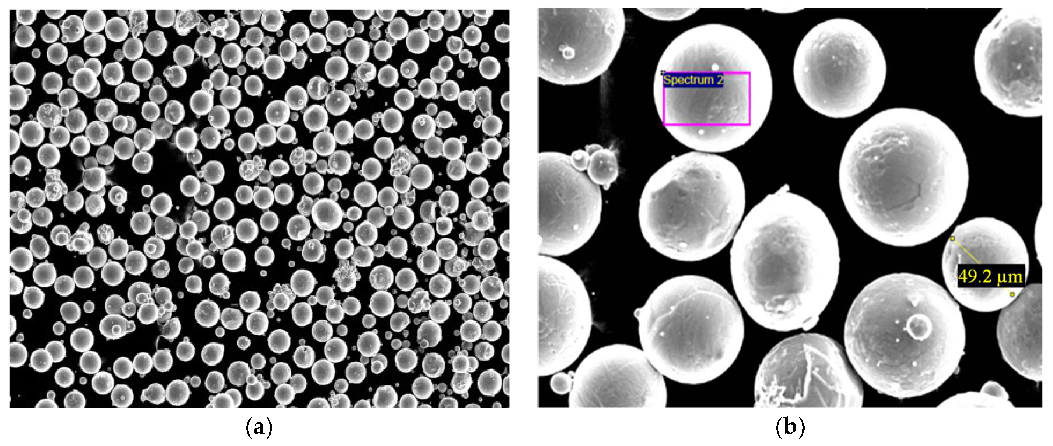
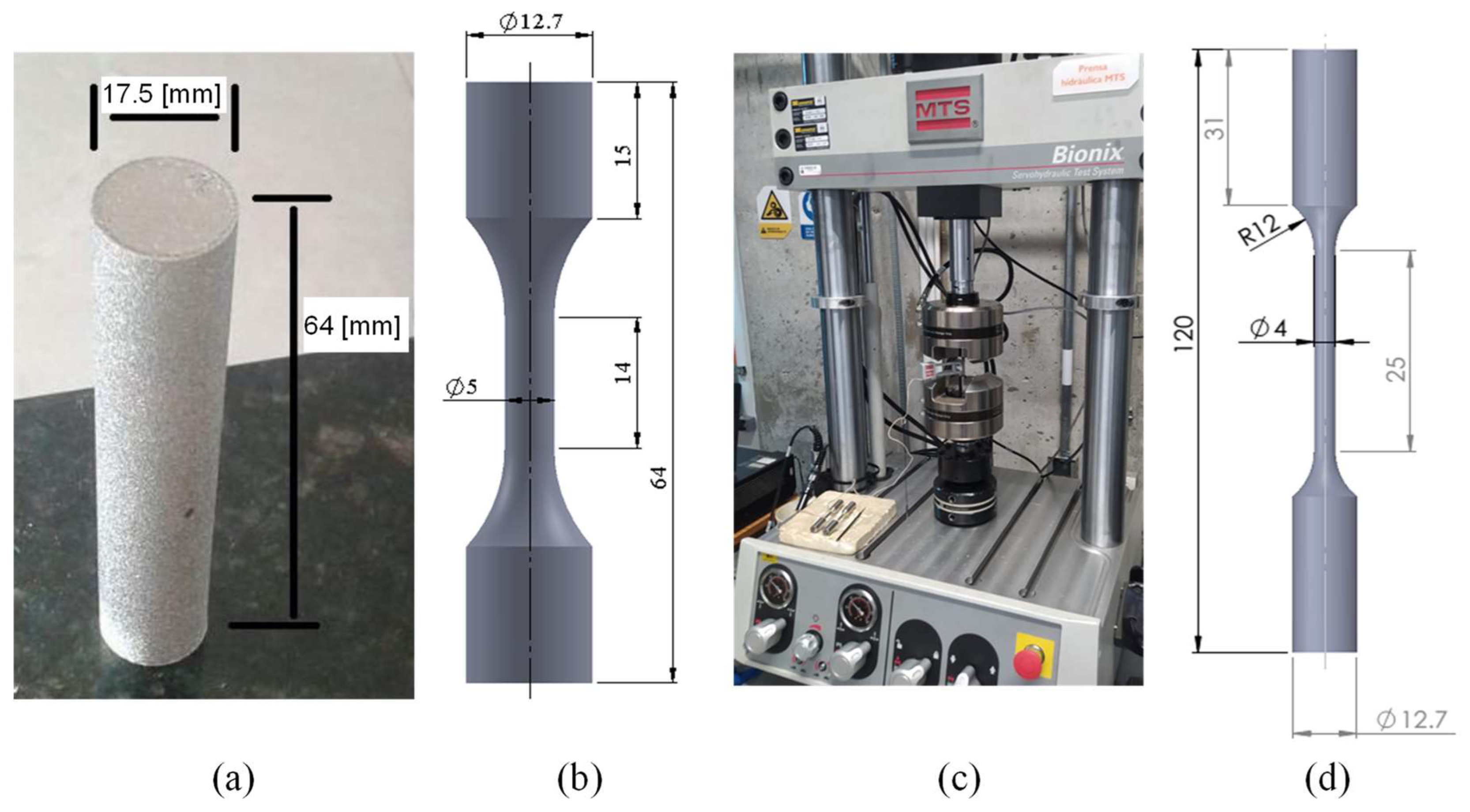
2. Materials and Methods
3. Results
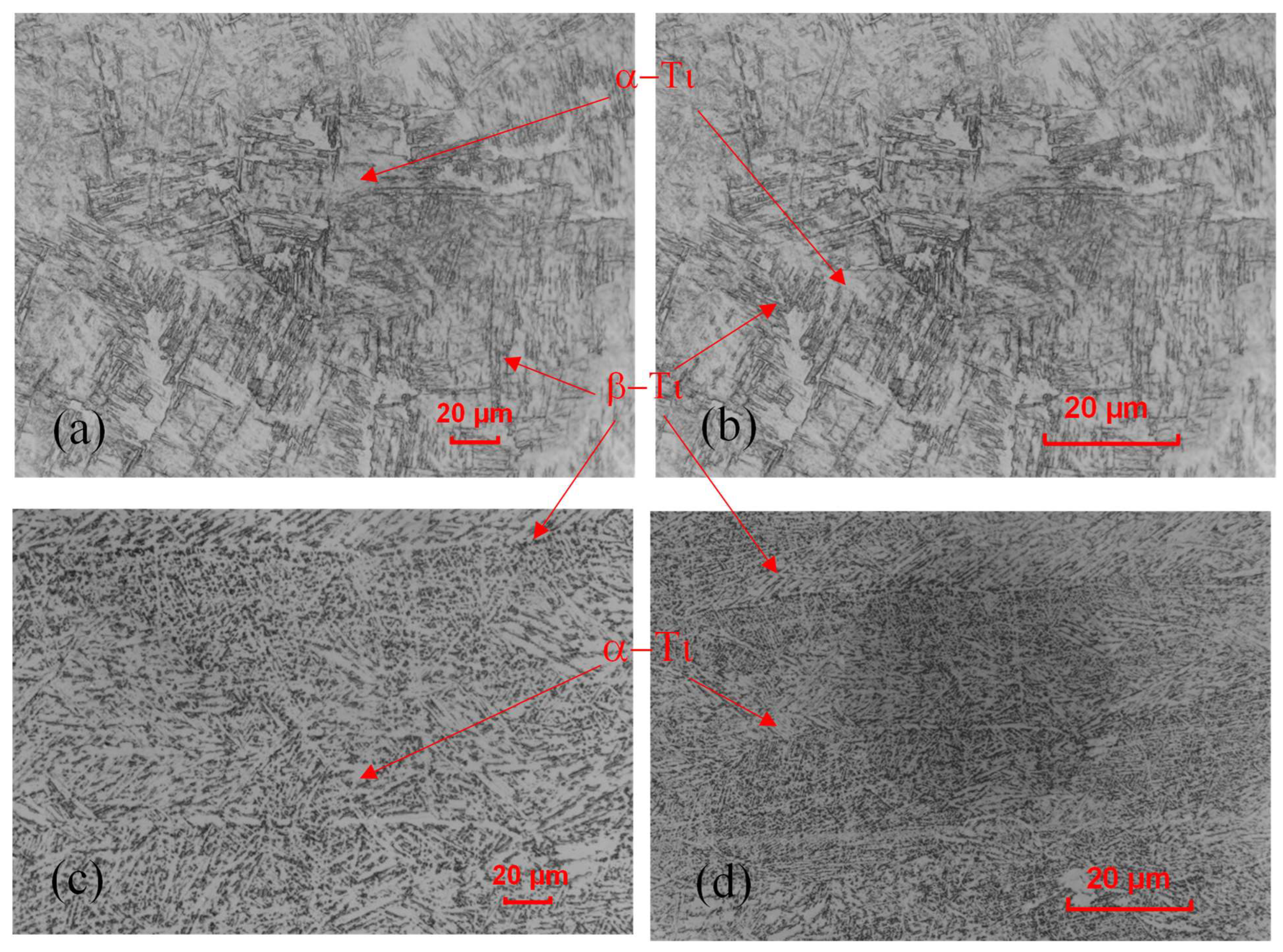
3.1. Microstructure
- Grain size: columnar grains in the XZ plane and faceted grains in the XY plane
- The thickness of the grain edge of the phase α between the grains β.
- The α plate thickness and α colony size (aspect ratio).
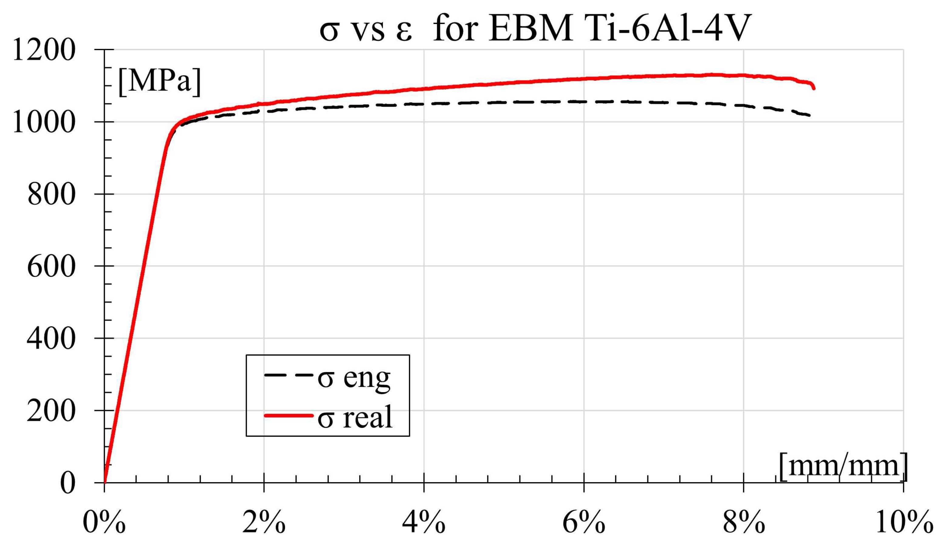
3.2. Tensile Test
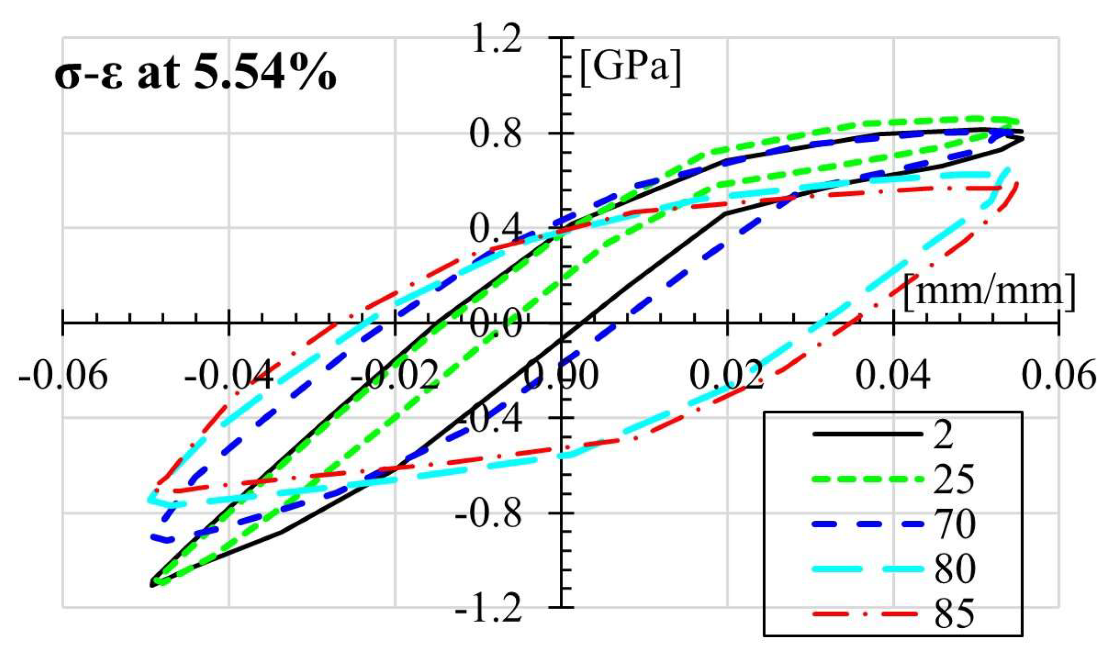
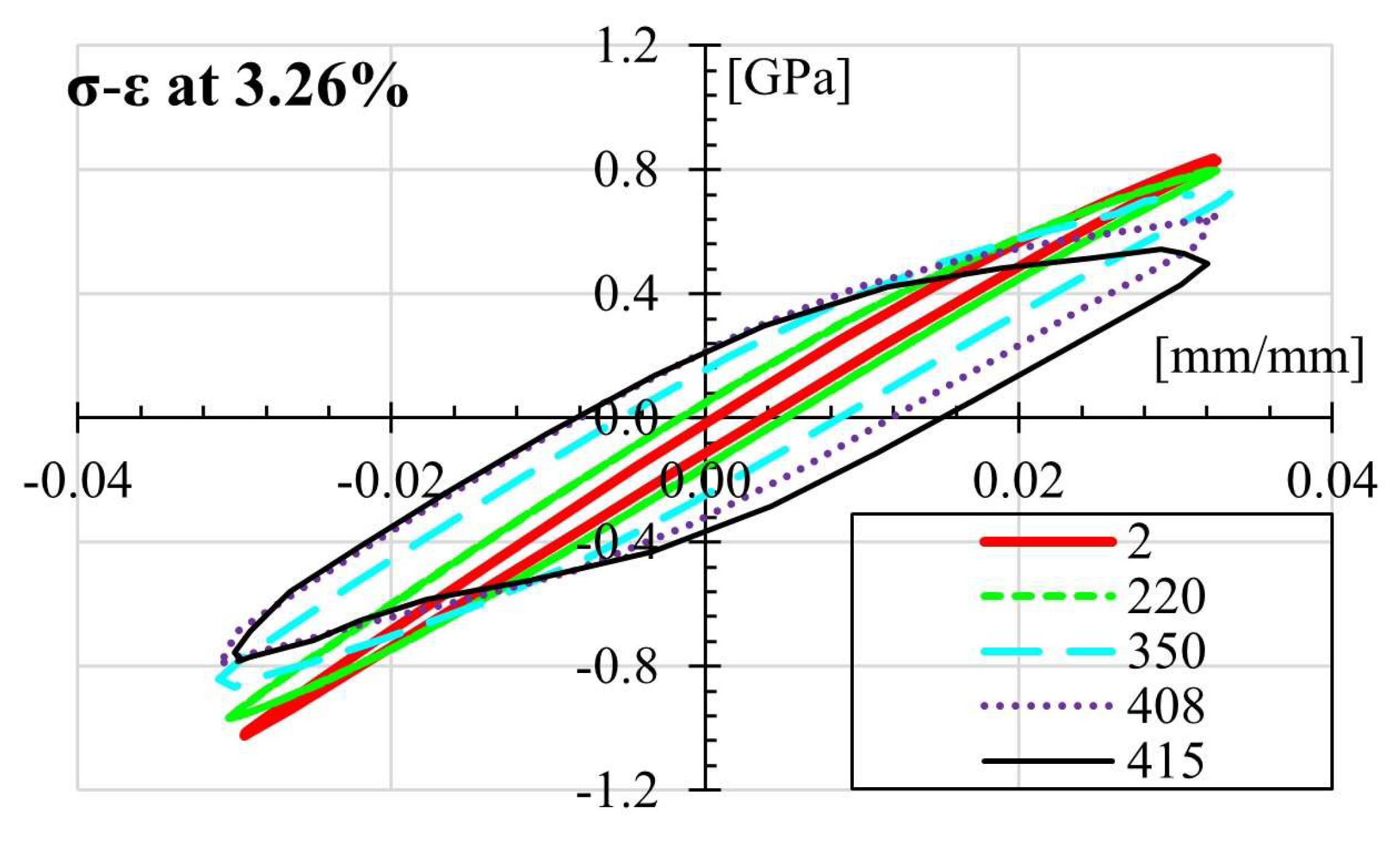
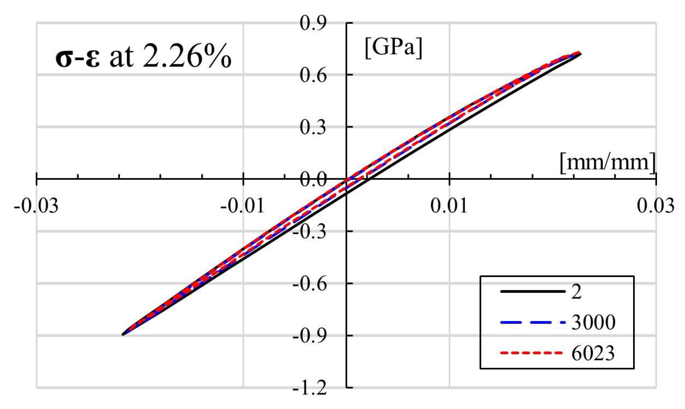
3.3. Fatigue Tests
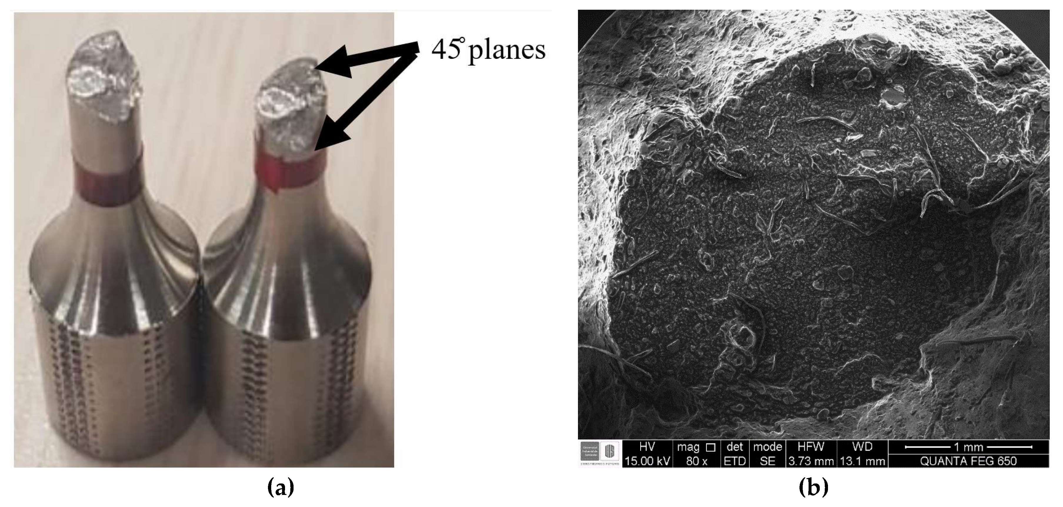
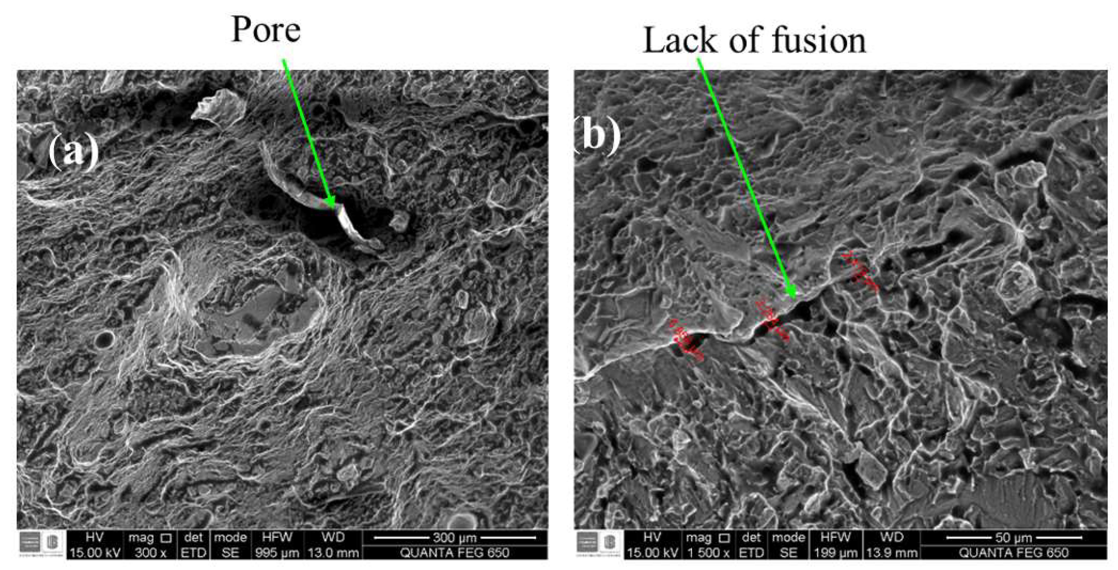
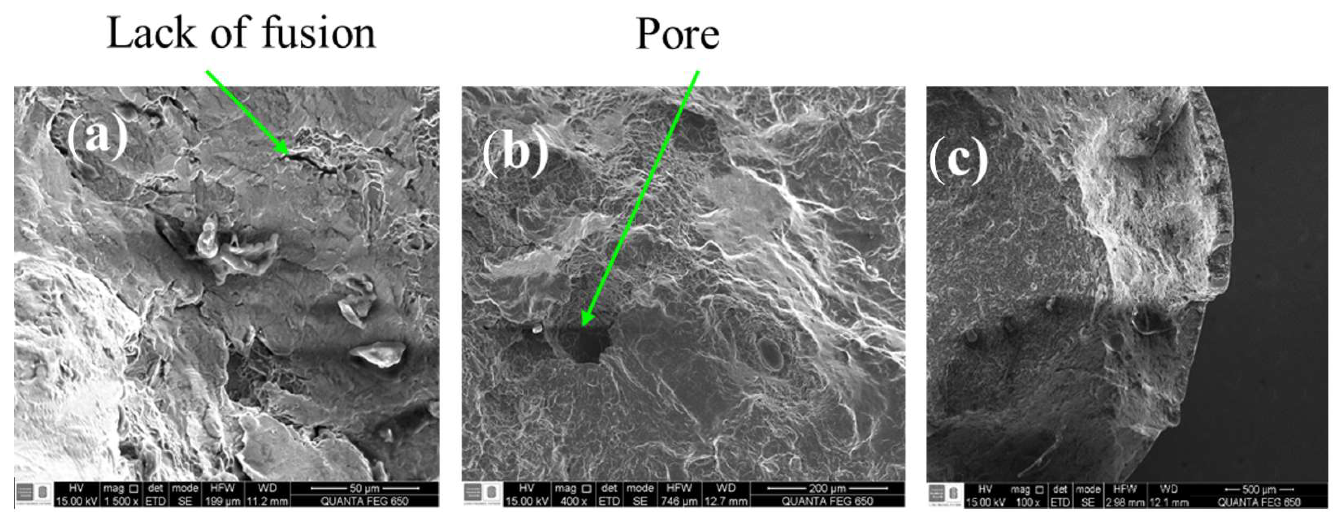
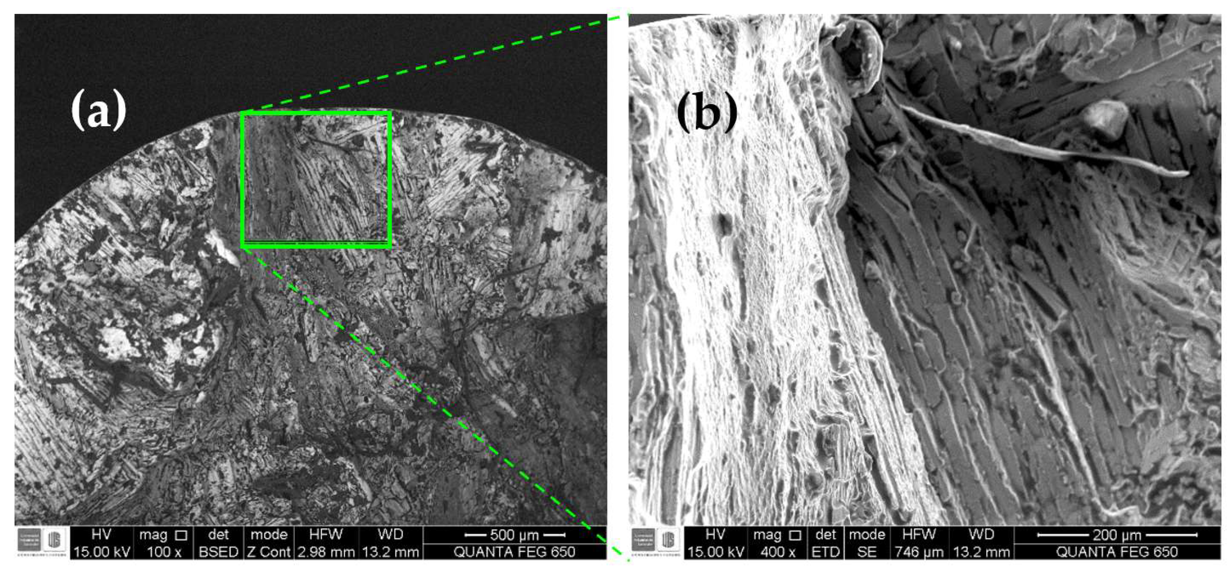
3.4. Fractured Surface Morphology Analysis
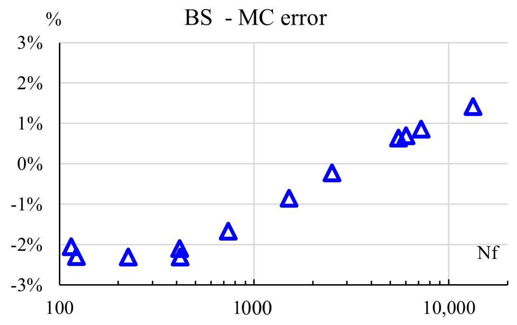
4. Discussion
5. Conclusions
Author Contributions
Funding
Data Availability Statement
Acknowledgments
Conflicts of Interest
Nomenclature
| AM | additive manufacturing |
| EBM | electron beam melting |
| elastic strain | |
| plastic strain | |
| true stress | |
| ultimate stress | |
| yield stress | |
| fracture stress | |
| Nf | number of cycles to failure |
| b, c | material dependent constants for the Coffin−Manson rule |
| R | load inversion rate |
| X, Y | directions perpendicular to printing |
| Z | printing direction |
References
- Wanjara, P.; Backman, D.; Sikan, F.; Gholipour, J.; Amos, R.; Patnaik, P.; Brochu, M. Microstructure and Mechanical Properties of Ti-6Al-4V Additively Manufactured by Electron Beam Melting with 3D Part Nesting and Powder Reuse Influences. J. Manuf. Mater. Process. 2022, 6, 21. [Google Scholar] [CrossRef]
- Yates, J.R.; Efthymiadis, P.; Antonysamy, A.A.; Pinna, C.; Tong, J. Do additive manufactured parts deserve better? Fatigue Fract. Eng. Mater. Struct. 2019, 42, 2146–2154. [Google Scholar] [CrossRef]
- Rafi, H.K.; Karthik, N.V.; Gong, H.; Starr, T.L.; Stucker, B.E. Microstructures and Mechanical Properties of Ti6Al4V Parts Fabricated by SLM and EBM. J. Mater. Eng. Perform. 2013, 22, 3872–3883. [Google Scholar] [CrossRef]
- Frazier, W.E. Metal Additive Manufacturing: A Review. J. Mater. Eng. Perform. 2014, 23, 1917–1928. [Google Scholar] [CrossRef]
- Obermayer, T.; Krempaszky, C.; Werner, E. Analysis of Texture and Anisotropic Elastic Properties of Additively Manufactured Ni-Base Alloys. Metals 2022, 12, 1991. [Google Scholar] [CrossRef]
- Erdakov, I.; Glebov, L.; Pashkeev, K.; Bykov, V.; Bryk, A.; Lezin, V.; Radionova, L. Effect of the Ti6Al4V Alloy Track Trajectories on Mechanical Properties in Direct Metal Deposition. Machines 2020, 8, 79. [Google Scholar] [CrossRef]
- Beretta, S.; Romano, S. A comparison of fatigue strength sensitivity to defects for materials manufactured by AM or traditional processes. Int. J. Fatigue. 2017, 94, 178–191. [Google Scholar] [CrossRef]
- Tamayo, J.A.; Riascos, M.; Vargas, C.A.; Baena, L.M. Additive manufacturing of Ti6Al4V alloy via electron beam melting for the development of implants for the biomedical industry. Heliyon 2021, 7, e06892. [Google Scholar] [CrossRef]
- Castro, J.T.P.; Meggiolaro, M.A. Fatigue Design Techniques, 3rd ed.; CreateSpace: Scotts Valley, CA, USA, 2016. [Google Scholar]
- Liu, S.; Shin, Y.C. Additive manufacturing of Ti6Al4V alloy: A review. Mater. Des. 2019, 164, 107552. [Google Scholar] [CrossRef]
- Corredor, E.; González-Estrada, O.A.; Ospina-Ospina, R. Deposición de láser pulsado de hidroxiapatita en Ti-6Al-4V producido por manufactura aditiva. Rev. UIS Ing. 2022, 21, 107–122. [Google Scholar]
- González-Estrada, O.A.; Pertuz Comas, A.D.; Ospina, R. Characterization of hydroxyapatite coatings produced by pulsed-laser deposition on additive manufacturing Ti6Al4V ELI. Thin Solid Films 2022, 763, 139592. [Google Scholar] [CrossRef]
- León, B.J.; Díaz-Rodríguez, J.G.; González-Estrada, O.A. Daño en partes de manufactura aditiva reforzadas por fibras continuas. Rev. UIS Ing. 2020, 19, 161–175. [Google Scholar] [CrossRef]
- Parrado-Agudelo, J.Z.; Narváez-Tovar, C. Mechanical characterization of polylactic acid, polycaprolactone and Lay-Fomm 40 parts manufactured by fused deposition modeling, as a function of the printing parameters. ITECKNE 2019, 16, 25–31. [Google Scholar] [CrossRef] [Green Version]
- Fatemi, A.; Molaei, R.; Sharifimehr, S.; Shamsaei, N.; Phan, N. Torsional fatigue behavior of wrought and additive manufactured Ti-6Al-4V by powder bed fusion including surface finish effect. Int. J. Fatigue 2017, 99, 187–201. [Google Scholar] [CrossRef]
- Wang, P.; Sin, W.J.; Nai, M.L.S.; Wei, J. Effects of Processing Parameters on Surface Roughness of Additive Manufactured Ti-6Al-4V via Electron Beam Melting. Materials 2017, 10, 1121. [Google Scholar] [CrossRef] [Green Version]
- Günther, J.; Krewerth, D.; Lippmann, T.; Leuders, S.; Tröster, T.; Weidner, A.; Biermann, H.; Niendorf, T. Fatigue life of additively manufactured Ti–6Al–4V in the very high cycle fatigue regime. Int. J. Fatigue 2017, 94, 236–245. [Google Scholar] [CrossRef]
- Meggiolaro, M.; de Castro, J.T.P. Statistical evaluation of strain-life fatigue crack initiation predictions. Int. J. Fatigue 2004, 26, 463–476. [Google Scholar] [CrossRef]
- Chastand, V.; Quaegebeur, P.; Maia, W.; Charkaluk, E. Comparative study of fatigue properties of Ti-6Al-4V specimens built by electron beam melting (EBM) and selective laser melting (SLM). Mater. Charact. 2018, 143, 76–81. [Google Scholar] [CrossRef]
- Agius, D.; Kourousis, K.I.; Wallbrink, C. Elastoplastic response of as-built SLM and wrought Ti-6Al-4V under symmetric and asymmetric strain-controlled cyclic loading. Rapid. Prototyp. J. 2018, 24, 1409–1420. [Google Scholar] [CrossRef]
- Bourell, D.; Kruth, J.P.; Leu, M.; Levy, G.; Rosen, D.; Beese, A.M.; Clare, A. Materials for additive manufacturing. CIRP Ann. 2017, 66, 659–681. [Google Scholar] [CrossRef]
- Kasperovich, G.; Hausmann, J. Improvement of fatigue resistance and ductility of TiAl6V4 processed by selective laser melting. J. Mater. Process. Technol. 2015, 220, 202–214. [Google Scholar] [CrossRef]
- Le, V.-D.; Pessard, E.; Morel, F.; Prigent, S. Fatigue behaviour of additively manufactured Ti-6Al-4V alloy: The role of defects on scatter and statistical size effect. Int. J. Fatigue 2020, 140, 105811. [Google Scholar] [CrossRef]
- Biswas, N.; Ding, J.L.; Balla, V.K.; Field, D.P.; Bandyopadhyay, A. Deformation and fracture behavior of laser processed dense and porous Ti6Al4V alloy under static and dynamic loading. Mater. Sci. Eng. A 2012, 549, 213–221. [Google Scholar] [CrossRef]
- de Formanoir, C.; Michotte, S.; Rigo, O.; Germain, L.; Godet, S. Electron beam melted Ti–6Al–4V: Microstructure, texture and mechanical behavior of the as-built and heat-treated material. Mater. Sci. Eng. A 2016, 652, 105–119. [Google Scholar] [CrossRef]
- Hrabe, N.; Gnäupel-Herold, T.; Quinn, T. Fatigue properties of a titanium alloy (Ti–6Al–4V) fabricated via electron beam melting (EBM): Effects of internal defects and residual stress. Int. J. Fatigue 2017, 94, 202–210. [Google Scholar] [CrossRef] [Green Version]
- Kahlin, M.; Ansell, H.; Moverare, J.J. Fatigue behaviour of notched additive manufactured Ti6Al4V with as-built surfaces. Int. J. Fatigue 2017, 101, 51–60. [Google Scholar] [CrossRef]
- Franchitti, S.; Pirozzi, C.; Borrelli, R. Influence of hot isostatic pressing and surface finish on the mechanical behaviour of Ti6Al4V processed by electron beam melting. Fatigue Fract. Eng. Mater. Struct. 2020, 43, 2828–2841. [Google Scholar] [CrossRef]
- Toasa Caiza, P.D.; Sire, S.; Ummenhofer, T.; Uematsu, Y. Low cost estimation of Wöhler and Goodman–Haigh curves of Ti-6Al-4V samples by considering the stress ratio effect. Fatigue Fract. Eng. Mater. Struct. 2021, 45, 441–450. [Google Scholar] [CrossRef]
- Chern, A.H.; Nandwana, P.; Yuan, T.; Kirka, M.M.; Dehoff, R.R.; Liaw, P.K.; Duty, C.E. A review on the fatigue behavior of Ti-6Al-4V fabricated by electron beam melting additive manufacturing. Int. J. Fatigue 2019, 119, 173–184. [Google Scholar] [CrossRef]
- Sterling, A.; Shamsaei, N.; Torries, B.; Thompson, S.M. Fatigue Behaviour of Additively Manufactured Ti-6Al-4 v. Procedia Eng. 2015, 133, 576–589. [Google Scholar] [CrossRef] [Green Version]
- Bressan, S.; Ogawa, F.; Itoh, T.; Berto, F. Low cycle fatigue behavior of additively manufactured Ti-6Al-4V under non-proportional and proportional loading. Frattura Ed. Integrità Strutturale 2019, 13, 18–25. [Google Scholar] [CrossRef]
- Radlof, W.; Benz, C.; Heyer, H.; Sander, M. Monotonic and Fatigue Behavior of EBM Manufactured Ti-6Al-4V Solid Samples: Experimental, Analytical and Numerical Investigations. Materials 2020, 13, 4642. [Google Scholar] [CrossRef] [PubMed]
- Bai, C.; Lan, L.; Xin, R.; Gao, S.; He, B. Microstructure evolution and cyclic deformation behavior of Ti-6Al-4 V alloy via electron beam melting during low cycle fatigue. Int. J. Fatigue 2022, 159, 106784. [Google Scholar] [CrossRef]
- Zhang, P.; Z.Zhang, D.; Zhong, B. Constitutive and damage modelling of selective laser melted Ti-6Al-4V lattice structure subjected to low cycle fatigue. Int. J. Fatigue 2022, 159, 106800. [Google Scholar] [CrossRef]
- Carrion, P.E.; Shamsaei, N. Strain-based fatigue data for Ti–6Al–4V ELI under fully-reversed and mean strain loads. Data Brief. 2016, 7, 12–15. [Google Scholar] [CrossRef] [Green Version]
- Galarraga, H.; Warren, R.J.; Lados, D.A.; Dehoff, R.R.; Kirka, M.M.; Nandwana, P. Effects of heat treatments on microstructure and properties of Ti-6Al-4V ELI alloy fabricated by electron beam melting (EBM). Mater. Sci. Eng. A 2017, 685, 417–428. [Google Scholar] [CrossRef] [Green Version]
- Greitemeier, D.; Palm, F.; Syassen, F.; Melz, T. Fatigue performance of additive manufactured TiAl6V4 using electron and laser beam melting. Int. J. Fatigue 2017, 94, 211–217. [Google Scholar] [CrossRef]
- Molaei, R.; Fatemi, A.; Sanaei, N.; Pegues, J.; Shamsaei, N.; Shao, S.; Li, P.; Warner, D.; Phan, N. Fatigue of additive manufactured Ti-6Al-4V, Part II: The relationship between microstructure, material cyclic properties, and component performance. Int. J. Fatigue 2020, 132, 105363. [Google Scholar] [CrossRef]
- Téllez Fontecha, G.E.; Díaz, R.J.G. Análisis de falla del árbol de levas de un motor de seis cilindros en línea. ITECKNE 2009, 6, 56–62. [Google Scholar] [CrossRef] [Green Version]
- Pantazopoulos, G. A Short Review on Fracture Mechanisms of Mechanical Components Operated under Industrial Process Conditions: Fractographic Analysis and Selected Prevention Strategies. Metals 2019, 9, 148. [Google Scholar] [CrossRef]


| Author | Year | Method | Tests | Fatigue Modeling | Comments |
|---|---|---|---|---|---|
| Kasperovich and Hausmann [22] | 2015 | EBM | tension, HCF, SEM, HV | N/A | heat treatment, R = −1 |
| Sterling et al. [31] | 2015 | LENS | Tension, LCF, SEM | Coffin-Manson & Ramberg-Osgood | R = −1 |
| Galarraga et al. [37] | 2016 | EBM | Tension, SEM | N/A | Different cooling ratios |
| Carrion [36] | 2016 | Tension | Different loading ratios | ||
| Fatemi et al. [15] | 2017 | PBF | torsion, HCF | N/A | heat treatment, R = −1 |
| Günther et al. [17] | 2017 | SLM | HCF, VHCF, SEM | N/A | heat treatment |
| EBM | HCF, VHCF, SEM | N/A | as built | ||
| Agius et al. [20] | 2017 | SLM | tension, LCF, SEM, XRD | Frederick-Amstrong | as-built material, different R ratios |
| Hrabe et al. [26] | 2017 | EBM | Tension, microstructure, HCF, residual stresses | N/A | as-built, heat treatment, R = 0.1 |
| Kahlin et al. [27] | 2017 | EBM | HV, HCF, roughness, SEM | N/A | notch sensitivity, R = 0.1 |
| LS | HV, HCF, roughness, SEM | N/A | notch sensitivity, R = 0.1 | ||
| Chastand et al. [19] | 2018 | SLM | Tension, HCF, SEM | N/A | Different printing orientations, heat treatment, and surface finishing |
| EBM | Tension, HCF, SEM | N/A | Different printing orientations, heat treatment, and surface finishing | ||
| Bressan et al. [32] | 2019 | SLS | Multiaxial fatigue | N/A | Proportional and non-proportional load |
| Le et al. [23] | 2020 | SLM | Tension, HCF, X-ray tomography, SEM | Wöhler | R = 0.1 |
| Benz et al. [33] | 2020 | EBM | Tension, Fatigue, SEM | Coffin–Manson and Johnson–Cook | +1000 cycles |
| Toasa et al. [29] | 2021 | Stüssi | N/A | Different stress ratio | |
| Zhang et al. [35] | 2022 | EBM, SLS | |||
| Bai et al. [34] | 2022 | EBM | Coffin-Manson |
| Element | Al | V | C | Fe | O | N | H | Y | Ti |
|---|---|---|---|---|---|---|---|---|---|
| ASTM F2924 | 5.50–6.75 | 3.50–4.50 | Max. 0.08 | Max. 0.30 | Max. 0.20 | Max. 0.05 | Max. 0.015 | Max. 0.005 | Bal. |
| % weight | 6.48 | 3.96 | 0.01 | 0.15 | 0.14 | 0.01 | 0.004 | <0.001 | Bal. |
| Specimen | σy (MPa) | σu (MPa) | σf (MPa) | E (GPa) |
|---|---|---|---|---|
| 1 | 985 | 1088 | 971 | 124 |
| 2 | 1035 | 1142 | 1258 | 125 |
| 3 | 1031 | 1134 | 1061 | 120 |
| 4 | 1038 | 1151 | 1087 | 116 |
| 5 | 1025 | 1133 | 1135 | 118 |
| Mean | 1023 | 1130 | 1102 | 121 |
| Median | 1031 | 1134 | 1087 | 120 |
| Min. | 985 | 1088 | 971 | 116 |
| Max. | 1038 | 1151 | 1258 | 125 |
| SD | 22 | 25 | 105 | 4 |
| % ε | Nf | Coffin−Manson | Baumel−Seager | Meggiolaro−Castro | ||||||
|---|---|---|---|---|---|---|---|---|---|---|
| Δεp | Δεe | Δε | Δεp | Δεe | Δε | Δεp | Δεe | Δε | ||
| 5.54 | 115 | 0.00085 | 0.00000 | 0.0017 | 0.00821 | 0.00949 | 0.01770 | 0.0266 | 0.0077 | 0.0172 |
| 122 | 0.00083 | 0.00000 | 0.0017 | 0.00788 | 0.00944 | 0.01732 | 0.0265 | 0.0074 | 0.0170 | |
| 226 | 0.00059 | 0.00000 | 0.0012 | 0.00515 | 0.00890 | 0.01405 | 0.0247 | 0.0050 | 0.0148 | |
| 3.26 | 414 | 0.00038 | 0.00000 | 0.0008 | 0.00339 | 0.00840 | 0.01180 | 0.0231 | 0.0033 | 0.0132 |
| 417 | 0.00034 | 0.00000 | 0.0007 | 0.00338 | 0.00840 | 0.01177 | 0.0231 | 0.0033 | 0.0132 | |
| 736 | 0.00025 | 0.00000 | 0.0005 | 0.00228 | 0.00796 | 0.01024 | 0.0217 | 0.0023 | 0.0120 | |
| 2.88 | 1512 | 0.00017 | 0.00000 | 0.0003 | 0.00139 | 0.00743 | 0.00882 | 0.0201 | 0.0014 | 0.0107 |
| 2516 | 0.00013 | 0.00000 | 0.0003 | 0.00098 | 0.00708 | 0.00806 | 0.0190 | 0.0010 | 0.0100 | |
| 5511 | 0.00008 | 0.00000 | 0.0002 | 0.00057 | 0.00657 | 0.00714 | 0.0174 | 0.0006 | 0.0090 | |
| 2.26 | 6023 | 0.00008 | 0.00000 | 0.0002 | 0.00053 | 0.00652 | 0.00705 | 0.0172 | 0.0006 | 0.0089 |
| 7210 | 0.00008 | 0.00000 | 0.0002 | 0.00047 | 0.00640 | 0.00688 | 0.0169 | 0.0005 | 0.0087 | |
| 13335 | 0.00005 | 0.00000 | 0.0001 | 0.00031 | 0.00604 | 0.00635 | 0.0158 | 0.0003 | 0.0081 | |
Disclaimer/Publisher’s Note: The statements, opinions and data contained in all publications are solely those of the individual author(s) and contributor(s) and not of MDPI and/or the editor(s). MDPI and/or the editor(s) disclaim responsibility for any injury to people or property resulting from any ideas, methods, instructions or products referred to in the content. |
© 2023 by the authors. Licensee MDPI, Basel, Switzerland. This article is an open access article distributed under the terms and conditions of the Creative Commons Attribution (CC BY) license (https://creativecommons.org/licenses/by/4.0/).
Share and Cite
Pertuz-Comas, A.D.; González-Estrada, O.A.; Martínez-Díaz, E.; Villegas-Bermúdez, D.F.; Díaz-Rodríguez, J.G. Strain-Based Fatigue Experimental Study on Ti–6Al–4V Alloy Manufactured by Electron Beam Melting. J. Manuf. Mater. Process. 2023, 7, 25. https://doi.org/10.3390/jmmp7010025
Pertuz-Comas AD, González-Estrada OA, Martínez-Díaz E, Villegas-Bermúdez DF, Díaz-Rodríguez JG. Strain-Based Fatigue Experimental Study on Ti–6Al–4V Alloy Manufactured by Electron Beam Melting. Journal of Manufacturing and Materials Processing. 2023; 7(1):25. https://doi.org/10.3390/jmmp7010025
Chicago/Turabian StylePertuz-Comas, Alberto David, Octavio Andrés González-Estrada, Elkin Martínez-Díaz, Diego Fernando Villegas-Bermúdez, and Jorge Guillermo Díaz-Rodríguez. 2023. "Strain-Based Fatigue Experimental Study on Ti–6Al–4V Alloy Manufactured by Electron Beam Melting" Journal of Manufacturing and Materials Processing 7, no. 1: 25. https://doi.org/10.3390/jmmp7010025