
Manufacturing Method for Large Cylindrical Worm Gear Set of ISO Type I on Universal CNC Machine Tools

Abstract
:1. Introduction
2. Tooth Flanks of Worm and Worm Wheel
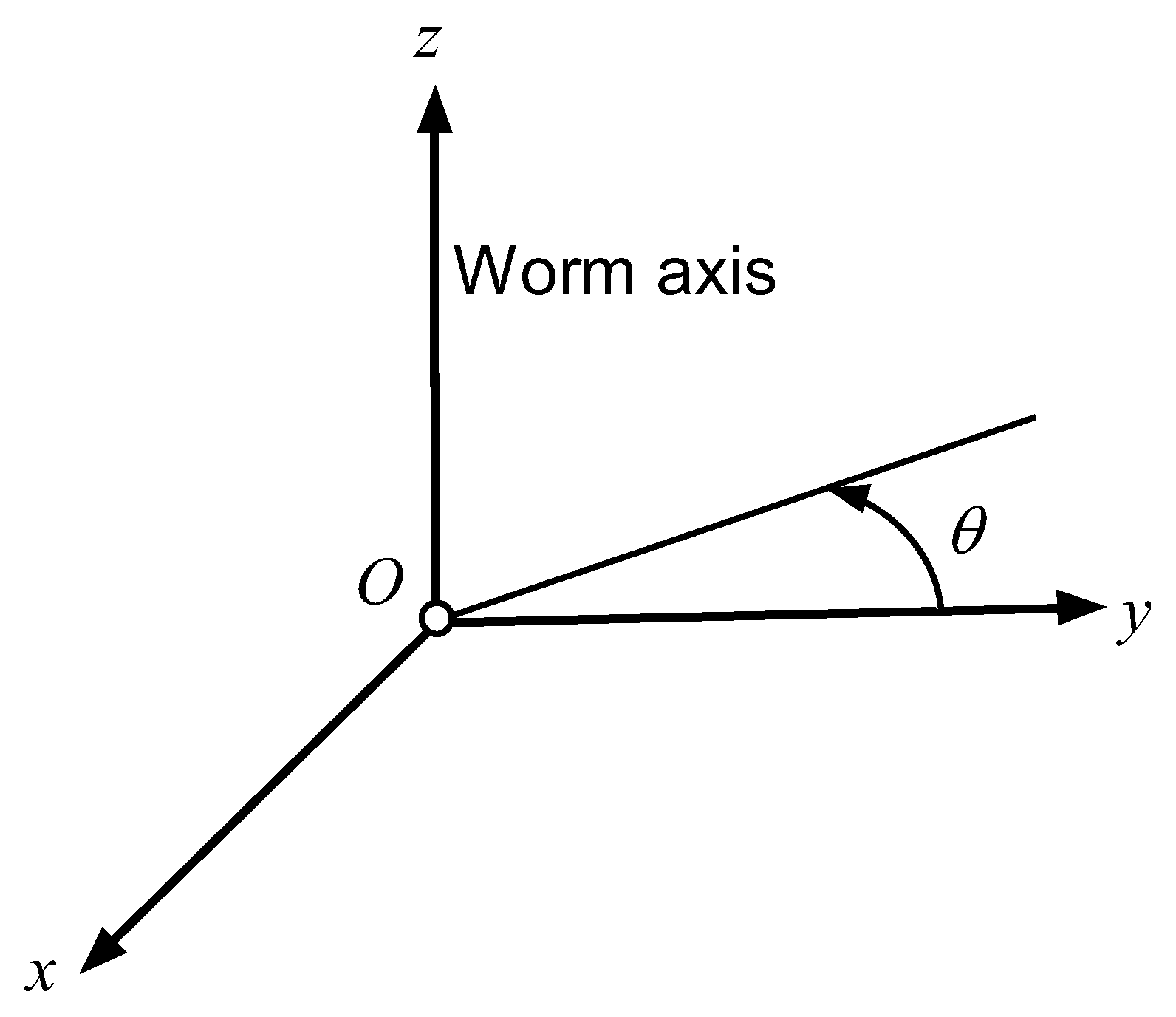
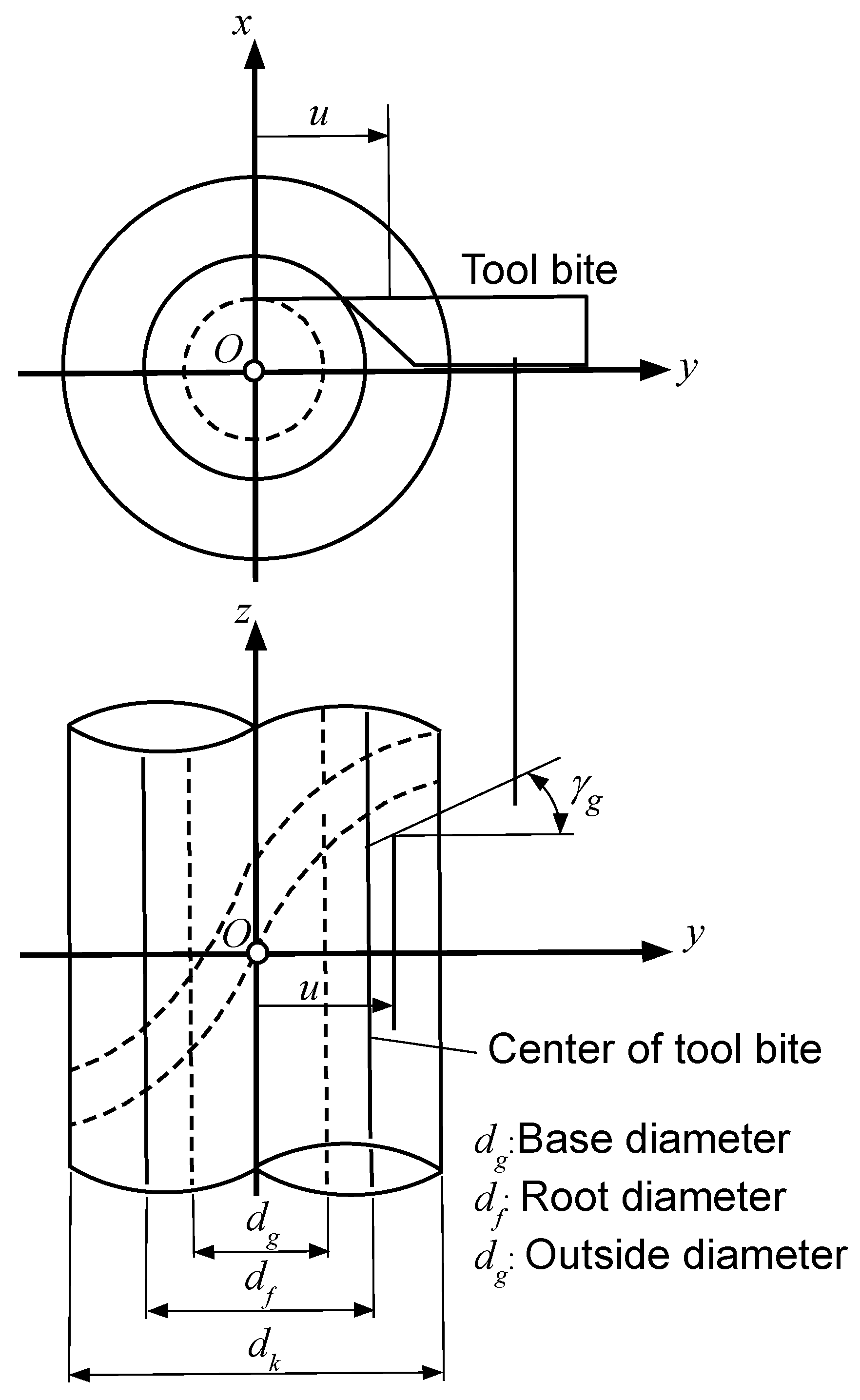
2.1. Tooth Flank of Worm
2.2. Tooth Flank of Worm Wheel
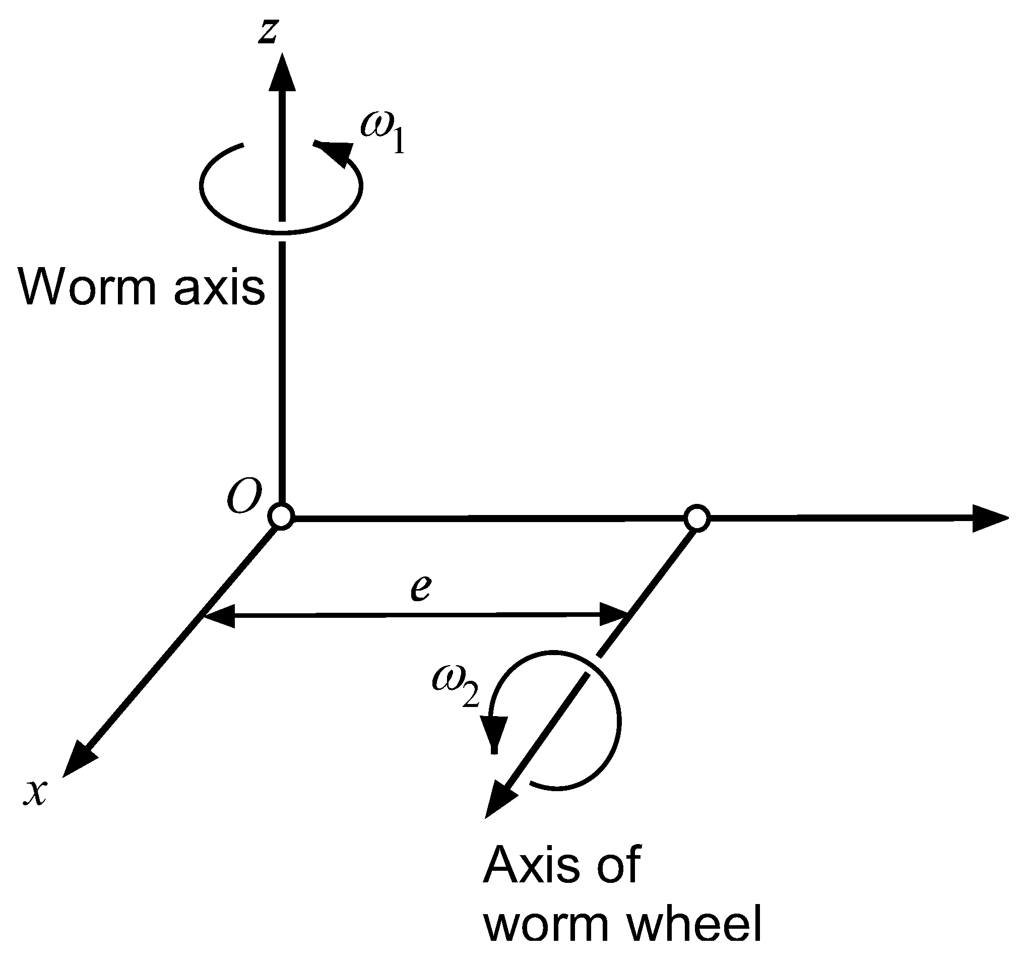
3. Tooth Contact Analysis of Worm Gear Set
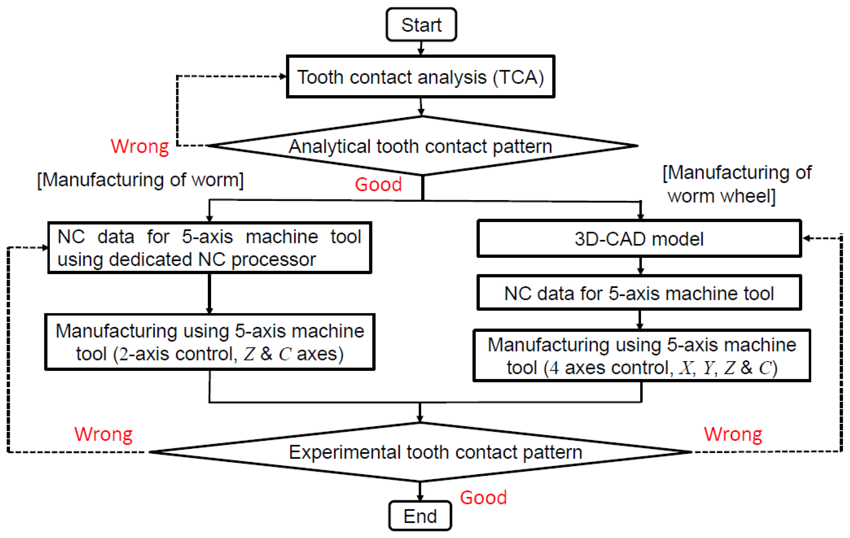
4. Manufacturing of Worm and Worm Wheel
4.1. Manufacturing of Worm
4.1.1. Offset-Cutting Method
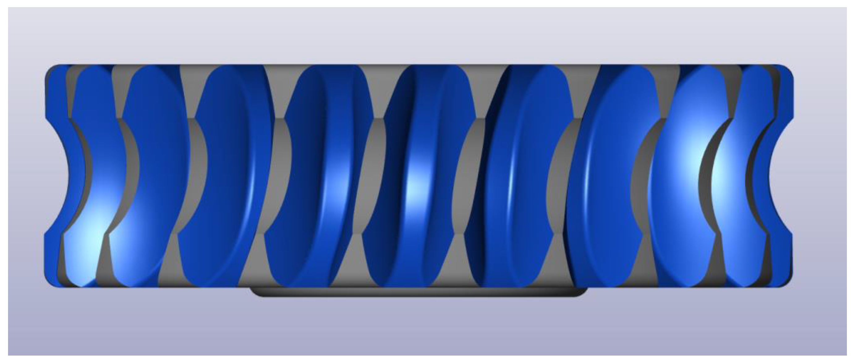
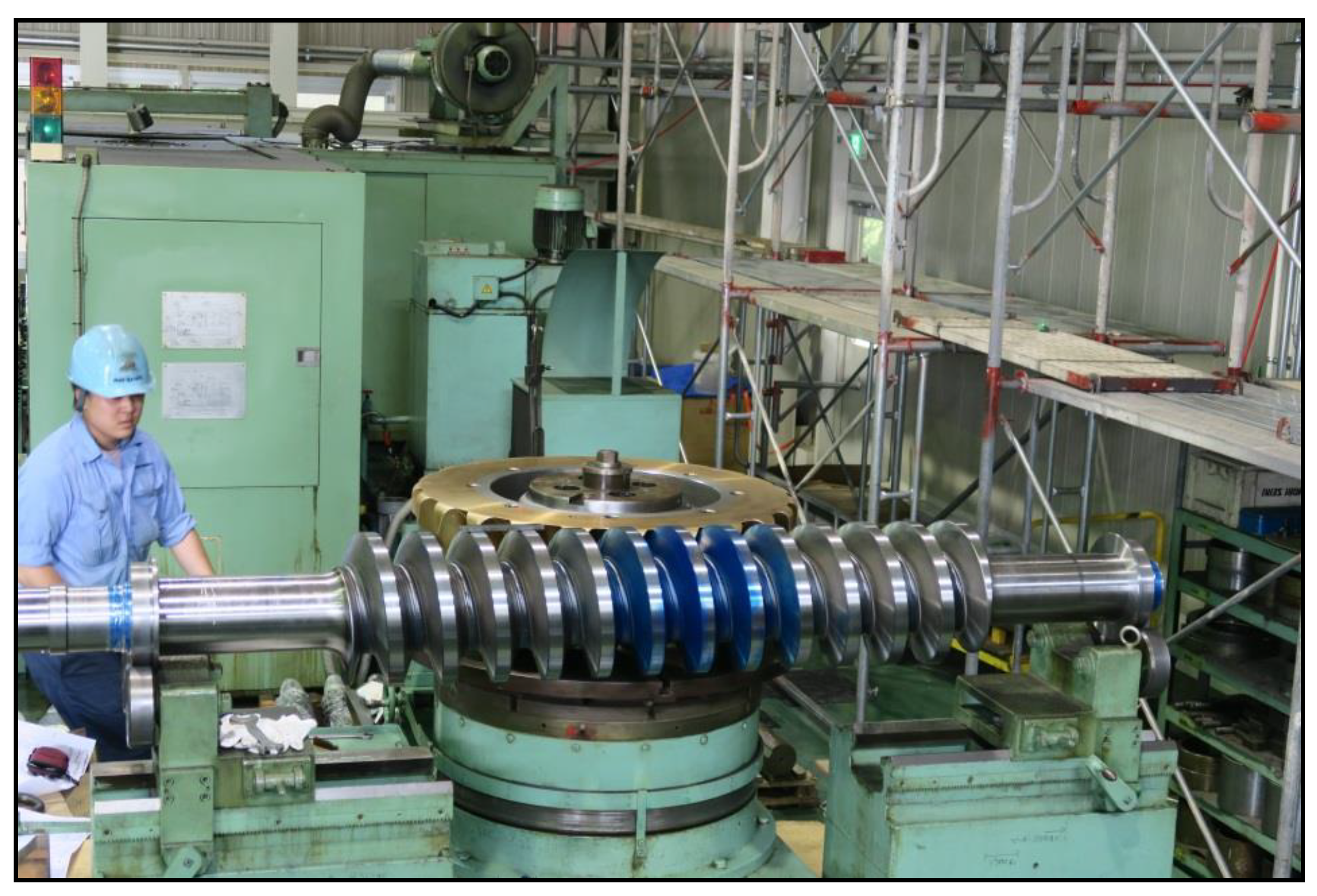
4.1.2. Manufacturing of Worm
4.2. Manufacturing of Worm Wheel
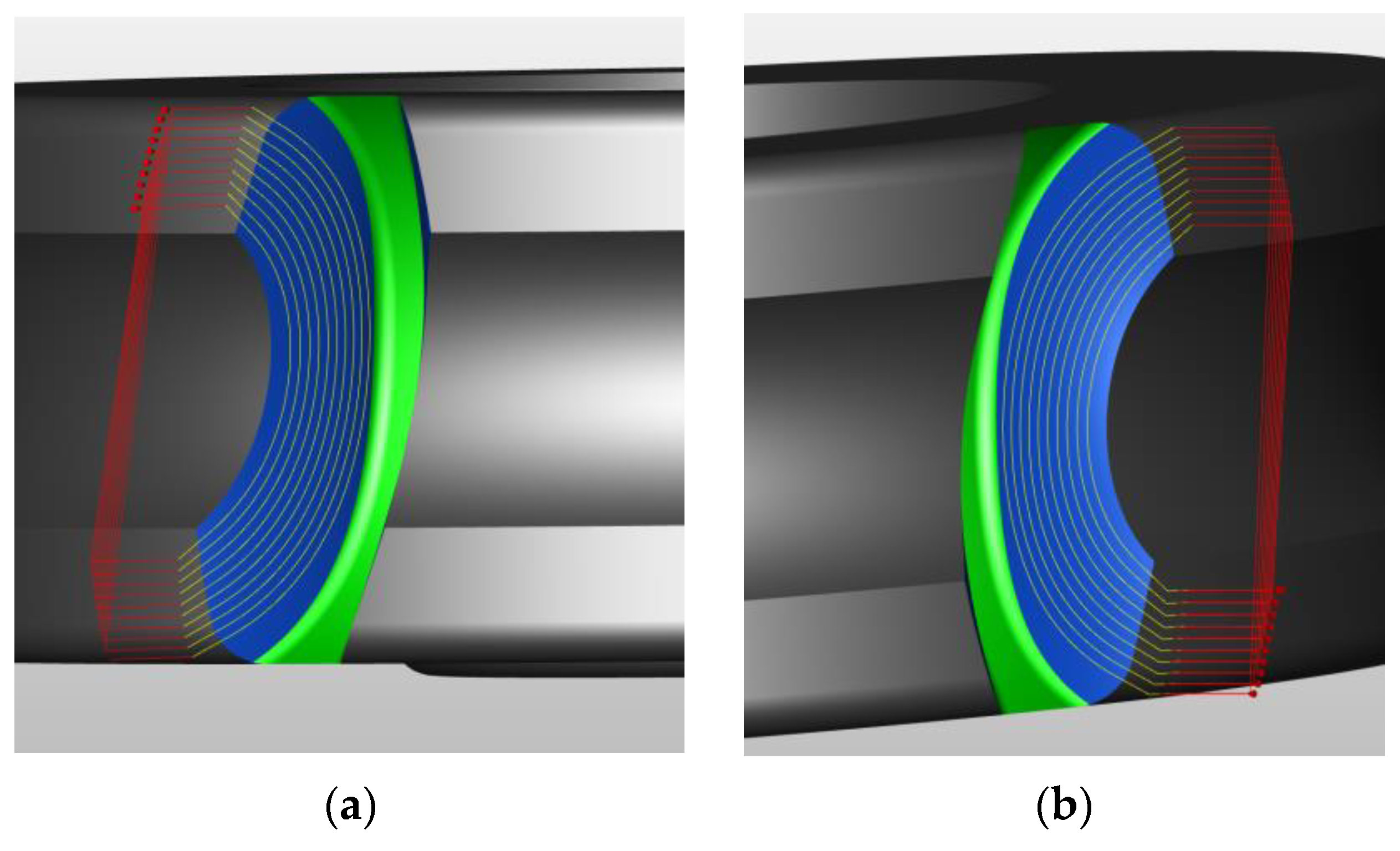
4.2.1. CAD/CAM Processes
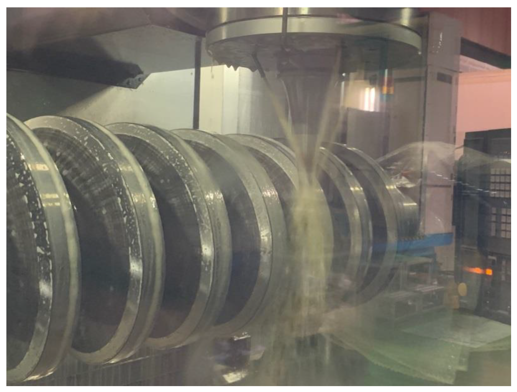
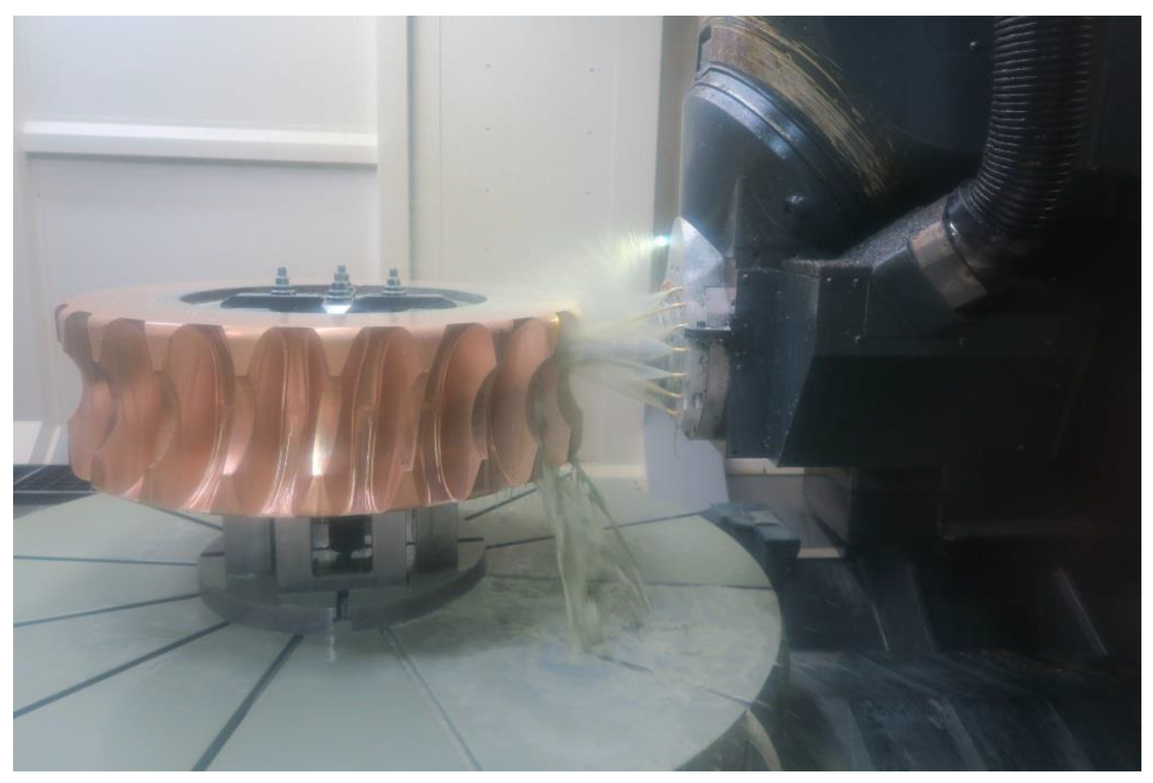
4.2.2. Manufacturing of Worm Wheel
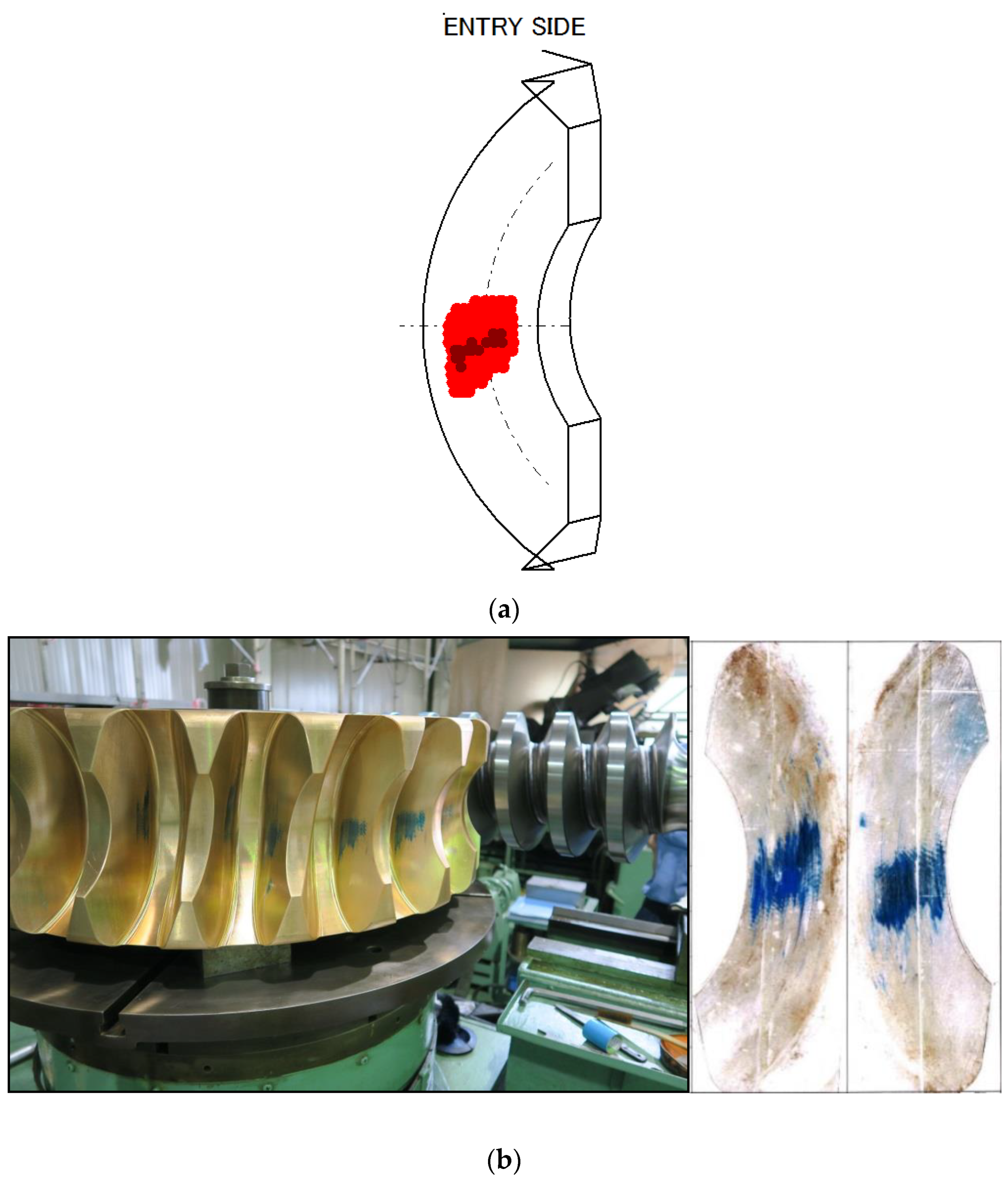
5. Experimental Tooth Contact Pattern
6. Conclusions
Author Contributions
Funding
Institutional Review Board Statement
Informed Consent Statement
Data Availability Statement
Conflicts of Interest
Nomenclature
| A, A’ | x components of position vector of generating line of tooth flank of worm in O-xyz |
| B, B’ | y components of position vector of generating line of tooth flank of worm in O-xyz |
| C, C’ | z components of position vector of generating line of tooth flank of worm in O-xyz |
| u, u’ | Variable position parameters on straight line of worm |
| x | Position vectors of tooth flank of worm in O-xyz |
| x | x components of position vector of tooth flank of worm in O-xyz |
| y | y components of position vector of tooth flank of worm in O-xyz |
| z | z components for z-axis of generating line of tooth flank of worm in O-xyz |
| i | Unit vector in the direction of x-axis |
| j | Unit vector in the direction of y-axis |
| k | Unit vector in the direction of z-axis |
| θ, θ’ | Angles of rotation of screw motion of generating line of the worm |
| θ1, θ1’ | Angles of rotation of worm |
| h, h’ | Pitches of screw motion |
| Pz | Axial displacement corresponding to one complete revolution |
| rg | Base cylindrical radius of worm |
| γg | Lead angle on base cylinder of worm |
| ω1 | Angular velocity vector of worm |
| ω2 | Angular velocity vector of worm wheel |
| v1 | Velocity vector of worm |
| v2 | Velocity vector of worm wheel |
| e | Offset distance between worm axis and axis of worm wheel |
| ε | Angular velocity ratio |
| w | Relative velocity of worm wheel with respect to worm |
| n | Surface unit normal of tooth flank of worm |
| x1 | Locus surface of contact lines |
| x2 | Tooth flank of worm wheel |
| A | Coordinate transform matrix with regard to rotation about x-axis |
| n2 | Surface unit normal of x2 |
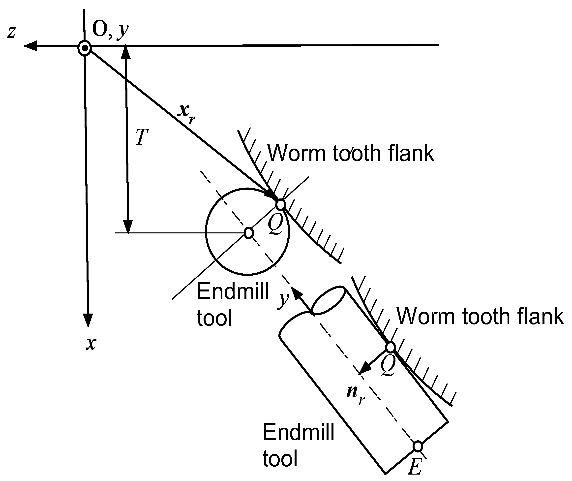
| Q | Contact point between the worm tooth flank and endmill tool |
| xr | Position vector of point Q in O-xyz |
| T | x component of right side of tooth space |
| nr | Surface unit normal of xr |
| ny | y component of nr |
| d | Diameter of endmill tool |
| nx | x component of nr |
| E | Rotational center of edge of endmill tool |
| xcr | Position vector of E of right side of tooth space in O-xyz |
| xcr | x component of xcr |
| ycr | y component of xcr |
| zcr | z component of xcr |
| nz | z component of nr |
| xcl | Position vector of E of left side of tooth space in O-xyz |
| xcl | x component of xcl |
| ycl | y component of xcl |
| zcl | z component of xcl |
References
- Vullo, V. Gears Volume 1: Geometric and Kinematic Design; Springer: Cham, Switzerland, 2020. [Google Scholar]
- Dudas, I. The Theory & Practice of Worm Gear Drives; Pen-Ton Press: London, UK, 2000. [Google Scholar]
- Davis, J.R. Gear Materials, Properties, and Manufacture; ASM International: Novelty, OH, USA, 2005. [Google Scholar]
- Radzevich, S.P. Dudley’s Handbook of Practical Gear Design and Manufacture, 4th ed.; CRC Press: Boca Raton, FL, USA; Taylor & Francis Group: New York, NY, USA, 2022. [Google Scholar]
- Kacalak, W.; Majewski, M.; Budniak, Z.; Ponomarenkow, J. Worm Gear Drive with Improved Kinematic Accuracy. Materials 2021, 14, 7825. [Google Scholar] [CrossRef] [PubMed]
- Simon, V.V. Characteristics of a New Type of Cylindrical Worm-Gear Drive. ASME. J. Mech. Des. 1998, 120, 139–146. [Google Scholar] [CrossRef]
- Shreehah, T.A.A.; Abdullah, R.A. Modification of Geometry and Technology of Cylindrical Worms. Mach. Sci. Technol. 2006, 10, 539–547. [Google Scholar] [CrossRef]
- Deng, X.; Wang, J.; Horstemeyer, M.F.; Solanki, K.N.; Zhang, J. Parametric Study of Meshing Characteristics with Respect to Different Meshing Rollers of the Antibacklash Double-Roller Enveloping Worm Gear. ASME J. Mech. Des. 2012, 134, 081004. [Google Scholar] [CrossRef]
- Litvin, F.L.; Gonzalez-Perez, I.; Yukishima, K.; Fuentes, A.; Hayasaka, K. Design, simulation of meshing, and contact stresses for an improved worm gear drive. Mech. Mach. Theory 2007, 42, 940–959. [Google Scholar] [CrossRef]
- Chen, W.L.; Tsay, C.B. Contact Characteristics of Recess Action Worm Gear Drives with Double-Depth Teeth. ASME J. Mech. Des. 2011, 133, 111006. [Google Scholar] [CrossRef] [Green Version]
- Jiaxing, Z.; Ilie, K. Static shear strength calculation of plastic helical gears mating with steel worm. Int. J. Precis. Eng. Manuf. 2014, 15, 235–239. [Google Scholar] [CrossRef]
- Sohn, J.; Park, N. Geometric interference in cylindrical worm gear drives using oversized hob to cut worm gears. Mech. Mach. Theory 2016, 100, 83–103. [Google Scholar] [CrossRef]
- Osakue, E.E.; Anetor, L. Design Sizing of Cylindrical Worm Gearsets. FME Trans. 2020, 48, 31–45. [Google Scholar] [CrossRef]
- Shi, Z.; Ren, J.; Feng, Z.; Li, J. Key Technology and Experimental Study of Unequal Pitches Meshing between Metal Worm and Plastic Helical Gears. Appl. Sci. 2021, 11, 333. [Google Scholar] [CrossRef]
- Liu, Y.; Zhao, Y.; Chen, X.; Li, G. Meshing theory of axial arc tooth profile cylindrical worm drive. Adv. Mech. Eng. 2021, 13, 16878140211012519. [Google Scholar] [CrossRef]
- Mu, S.; Zhao, Y.; Zhang, X.; Meng, Q.; Li, G. Meshing theory of involute worm drive. Mech. Mach. Theory 2021, 165, 104425. [Google Scholar] [CrossRef]
- Deng, X.; Hong, L.; Li, W.; Wang, S.; Liu, Y. High precision machining of ZC1 worm gear drives with large modulus. Mech. Mach. Theory 2021, 165, 104437. [Google Scholar] [CrossRef]
- Boral, P.; Gołębski, R. Technology of Manufacturing of ZC Cylindrical Worm. Materials 2022, 15, 6412. [Google Scholar] [CrossRef]
- Balajti, Z. Determination of Undercutting Avoidance for Designing the Production Technology of Worm Gear Drives with a Curved Profile. Machines 2023, 11, 56. [Google Scholar] [CrossRef]
- Sergej, N.G.; Martinov, G.M. Research and Development of a Cross-Platform CNC Kernel for Multi-Axis Machine Tool. Procedia CIRP 2014, 14, 517–522. [Google Scholar]
- Nakamoto, Y.; Takeuchi, Y. Recent Advances in Multi-Axis Control and Multitasking Machining. Int. J. Autom. Technol. 2017, 11, 140–154. [Google Scholar] [CrossRef]
- Suh, S.H.; Jih, W.S.; Hong, H.D.; Chung, D.H. Sculptured surface machining of spiral bevel gears with CNC milling. Int. J. Mach. Tools Manuf. 2001, 41, 833–850. [Google Scholar] [CrossRef]
- Kawasaki, K.; Tsuji, I.; Abe, Y.; Gunbara, H. Manufacturing Method of Large-Sized Spiral Bevel Gears in Cyclo-Palloid System Using Multi-Axis Control and Multi-Tasking Machine Tool. Proc. Int. Conf. Gears 2010, 1, 337–348. [Google Scholar]
- Yang, L.; Huang, G. The OPC technology research about spiral bevel gear machine tools for machining simulation problems. Procedia Eng. 2011, 15, 1266–1270. [Google Scholar] [CrossRef] [Green Version]
- Alves, J.T.; Guingand, M.; Vaujany, J. Designing and Manufacturing Spiral Bevel Gears Using 5-Axis Computer Numerical Control (CNC) Milling Machines. ASME J. Mech. Des. 2013, 135, 024502. [Google Scholar] [CrossRef]
- Deng, X.Z.; Li, G.G.; Wei, B.Y.; Deng, J. Face-milling spiral bevel gear tooth surfaces by application of 5-axis CNC machine tool. Int. J. Adv. Manuf. Technol. 2014, 71, 1049–1057. [Google Scholar] [CrossRef]
- Lei, B.; Cheng, G.; Lowe, H.; Wang, X. Remanufacturing the Pinion: An Application of a New Design Method for Spiral Bevel Gears. Adv. Mech. Eng. 2014, 2014, 257581. [Google Scholar] [CrossRef] [Green Version]
- Alvarez, A.; Lacalle, L.N.L.; Olaiz, A.; Rivero, A. Large spiral bevel gears on universal 5-axis milling machines: A complete process. Procedia Eng. 2015, 132, 397–404. [Google Scholar] [CrossRef] [Green Version]
- Malek, O.; Mielnik, K.; Martens, K.; Jacobs, T.; Bouquet, J.; Auwers, W.; Ten Haaf, P.; Lauwers, B. Lead time reduction by high precision 5-axis milling of a prototype gear. Procedia CIRP 2016, 46, 440–443. [Google Scholar] [CrossRef] [Green Version]
- Gosselin, C. Gear Tooth Edge Deburring and Chamfering in 5Axis CnC Manufacturing. Mech. Mach. Sci. 2021, 101, 153–184. [Google Scholar]
- Ozel, C.; Inan, A.; Ozler, L. An Investigation on Manufacturing of the Straight Bevel Gear Using End Mill by CNC Milling Machine. ASME J. Mech. Des. 2005, 127, 503–511. [Google Scholar]
- Kawasaki, K.; Tsuji, I.; Gunbara, H.; Houjoh, H. Method for remanufacturing large-sized skew bevel gears using CNC machining center. Mech. Mach. Theory 2015, 92, 213–229. [Google Scholar] [CrossRef]
- Gadakh, R.S.; Londhe, P.G.; Shaikh, B.A.; Shaikh, F.S. Gear Manufacturing by Using Conventional Lathe Machine. Int. J. Res. Eng. Technol. 2016, 5, 105–110. [Google Scholar]
- Gołębskiby, R.; Boral, P. Study of Machining of Gears with Regular and Modified Outline Using CNC Machine Tools. Materials 2021, 14, 2913. [Google Scholar] [CrossRef]
- Gołębskiby, R. Experimental Method of Machining Gears with an Involute Profile Using CNC Lathe with Driven Tools. Materials 2022, 15, 1077. [Google Scholar] [CrossRef] [PubMed]
- Kawasaki, K.; Tsuji, I.; Gunbara, H. Manufacturing method of double-helical gears using CNC machining center. Proc. Inst. Mech. Eng. Part C J. Mech. Eng. Sci. 2015, 230, 1149–1156. [Google Scholar] [CrossRef]
- Kawasaki, K.; Tsuji, I. Machining method of large-sized cylindrical worm gears with Niemann profiles using CNC machining center. Int. J. Adv. Manuf. Technol. 2019, 104, 3717–3729. [Google Scholar] [CrossRef]
- Sakai, T. A Study on the Tooth Profile of Hypoid Gears. Trans. JSME 1955, 21, 164–170. (In Japanese) [Google Scholar] [CrossRef] [Green Version]
- Litvin, F.L.; Fuentes, A. Gear Geometry and Applied Theory, 2nd ed.; Cambridge University Press: Cambridge, UK, 2004. [Google Scholar]


| Worm | Worm Wheel | |
|---|---|---|
| Number of teeth Outside diameter Mean diameter Tooth bottom diameter Face width Hand of spiral | 1 320.0 mm 260.0 mm 190.58 mm 1400.0 mm Right | 23 865.0 mm 805.0 mm 735.58 mm 275.0 mm Left |
| Tooth profile Central distance between axes of worm and worm wheel e Axial module Pressure angle Lead angle | ISO type Ⅰ 532.5 mm 35.0 20.0 deg. 7.6668 deg. | |
| Semi-Finishing | Finishing | |
|---|---|---|
| Diameter of endmill tool (mm) | 20.0 | 20.0 |
| Rotational speed (rpm) | 3000 | 3000 |
| Feed rate (mm/min) | 3000 | 2800 |
| Depth of cut (mm) | 0.1 × 2 | 0.02 |
| Milling pass (mm) | 0.63 | 0.3 |
| Time/one tooth (min) | 820 × 2 | 1845 |
| Semi-Finishing | Finishing | |
|---|---|---|
| Diameter of endmill tool (mm) | 16.0 | 16.0 |
| Rotational speed (rpm) | 2600 | 2600 |
| Feed rate (mm/min) | 1000 | 750 |
| Depth of cut (mm) | 0.1 | 0.02 |
| Milling pass (mm) | 4.8 | 1.0 |
| Time/one tooth (min) | 5 | 160 |
Disclaimer/Publisher’s Note: The statements, opinions and data contained in all publications are solely those of the individual author(s) and contributor(s) and not of MDPI and/or the editor(s). MDPI and/or the editor(s) disclaim responsibility for any injury to people or property resulting from any ideas, methods, instructions or products referred to in the content. |
© 2023 by the authors. Licensee MDPI, Basel, Switzerland. This article is an open access article distributed under the terms and conditions of the Creative Commons Attribution (CC BY) license (https://creativecommons.org/licenses/by/4.0/).
Share and Cite
Kawasaki, K.; Tsuji, I. Manufacturing Method for Large Cylindrical Worm Gear Set of ISO Type I on Universal CNC Machine Tools. J. Manuf. Mater. Process. 2023, 7, 53. https://doi.org/10.3390/jmmp7020053
Kawasaki K, Tsuji I. Manufacturing Method for Large Cylindrical Worm Gear Set of ISO Type I on Universal CNC Machine Tools. Journal of Manufacturing and Materials Processing. 2023; 7(2):53. https://doi.org/10.3390/jmmp7020053
Chicago/Turabian StyleKawasaki, Kazumasa, and Isamu Tsuji. 2023. "Manufacturing Method for Large Cylindrical Worm Gear Set of ISO Type I on Universal CNC Machine Tools" Journal of Manufacturing and Materials Processing 7, no. 2: 53. https://doi.org/10.3390/jmmp7020053