Article

Extrusion Additive Manufacturing of PEI Pellets

1
Dipartimento di Meccanica, Politecnico di Milano, 20156 Milan, Italy
2
Dipartimento di Ingegneria Industriale e dell’Informazione, Università degli Studi di Pavia, 27100 Pavia, Italy
*
Author to whom correspondence should be addressed.
J. Manuf. Mater. Process. 2022, 6(6), 157; https://doi.org/10.3390/jmmp6060157
Submission received: 12 November 2022 / Revised: 2 December 2022 / Accepted: 6 December 2022 / Published: 8 December 2022

Abstract

:
The simplest, most cost-efficient, and most widespread Additive Manufacturing (AM) technology is Extrusion Additive Manufacturing (EAM). Usually, EAM is performed with filament feedstock, but using pellets instead of filaments yields many benefits, including significantly lower cost and a wider choice of materials. High-performance polymers offer high strength even when produced with AM technique, allowing to produce near-net-shape functional parts. The production of these materials in filament form is still limited and expensive; therefore, in this paper, the possibility of producing AM components with engineering polymers from pellets will be thoroughly investigated. In this work, the effectiveness of a specially designed AM machine for printing high-performance materials in pellet form was tested. The material chosen for the investigation is PEI 1000 which offers outstanding mechanical and thermal properties, giving the possibility to produce with EAM functional components. Sensitivity analyses have been carried out to define a process window in terms of thermal process parameters by observing different response variables. Using the process parameters in the specified range, the additive manufactured material has been mechanically tested, and its microstructure has been investigated, both in dried and undried conditions. Finally, a rapid tool for sheet metal forming has been produced.

1. Introduction

The Additive Manufacturing industry has significantly grown in the past years and will continue to do so in the future due to the great extent of complexity and customization which can be achieved [1]. Many sectors are interested in additive manufacturing, including the automotive [2] and aerospace [3] ones, for which AM can become a promising route to produce molds and final components. The reasons why AM is gaining interest in these sectors are many, including the possibility of reducing prototyping cycle times, design flexibility, and low waste during production. Many steps are also being taken in order to enhance the bioprinting technology, which in the future could be used to produce organs for transplant as needed [4]. In the AM industry, the most commercially diffused technology is Extrusion Additive Manufacturing (EAM), which can be performed with feedstocks in the form of either filament or pellets. The latter offers greater possibilities in terms of the availability and diversity of printable materials, which are less expensive than filament feedstock [5]. In the past years, the EAM process has been increasingly used with high-performance thermoplastics [6] to increase the mechanical and thermal resistance of the produced parts. Many recent papers, the most relevant of them are cited here as follows, have been published on filament EAM with PEI (polyetherimide), but no scientific paper is present in the field of EAM of PEI pellets (to the author’s knowledge), which would reduce the cost of the printed objects dramatically.
PEI is regarded in the field of advanced engineering plastics, together with PEEK, PSU, PAI, and a few others. These polymers are characterized by steam resistance, high-temperature resistance, and good wear resistance [7]; therefore, they can be used for mechanically and thermally stressful applications. Machines used to perform AM with this kind of polymers often need specific characteristics, including a heated chamber, the possibility of heating the nozzle up to 450 °C, and a heated build plate capable of reaching at least 150 °C. The heated chamber can be fully sealed with oven-like resistances to keep it at a temperature or partially open with directed heating on the surrounding of the parts; in both cases, this helps increase bonding and diffusion among roads and enhances surface quality [8].
The main challenges present in producing extrusion additive manufactured components with advanced engineering plastics are related to thermal management during the print, which in turn affects mechanical properties, residual stresses, repeatability, and tolerances of the printed parts [7].
PEI is commonly known under its commercial name ULTEM™; it is a high-strength polymer with outstanding mechanical and thermal properties. It has good dimensional stability and excellent chemical resistance, being also food compatible. This polymer is able to maintain good mechanical properties up to 200 °C and has better flame-resistant features than many other polymers [9]. For these reasons, it is particularly suited to the production of rapid tools [10].
To improve the printability of the ULTEM™ material, PEI filaments designed for AM are often a blend of PEI and PC but they also contain many additives to reduce the high viscosity of PEI and improve the extrusion process in AM machines [7].
Many grades of the material are available on the market, each with slightly different properties intended for different applications. ULTEM™ 9085 is the most frequently used in EAM since it is easily available in filament form, but its mechanical and thermal properties are worse with respect to ULTEM™ 1000 or 1010. The typical mechanical properties of the three PEI grades are shown in Table 1.
The prices are considerably different between filaments and pellets, particularly for ULTEM™ and -temperature polymers, since producing calibrated filaments at extrusion temperatures around 400 °C is complicated and expensive. The purchase costs are obviously very variable from time to time, according to the market conditions. However, a typical ratio between the price of a small quantity of ULTEM™ 1000 in pellet form (25 kg) and a corresponding quantity of ULTEM™ 9085 or 1010 filaments is about 1 to 10.
Additively manufactured PEI 9085 and 1010 have been investigated deeply with respect to different aspects, including mechanical properties, isotropy [14], inter-layer adhesion [15], and the possibility of using carbon nanotubes to obtain electrically conductive PEI [16]. Attention has also been given to possible post-processing techniques, including annealing [17] and hot isostatic pressing [18]. Conversely, ULTEM™ 1000 produced with AM is not frequently studied in scientific literature. To the author’s knowledge, no scientific experimental study has been conducted yet in the field of extrusion additive manufacturing of PEI 1000 pellets. This paper aims to study the 3D printability of PEI 1000 directly from the pellet and characterize the resulting mechanical performance of 3D printed samples.
Being PEI an engineering thermoplastic, tolerances are of primary importance to produce net-shape parts that need to work in assemblies. For this reason, studies on the roughness and deviation of PEI AM-produced components are now being developed [19].
In the following Section 2, a comprehensive review of the scientific state of the art concerning the EAM of PEI is presented. The experimental setup and material used are presented in Section 3, while in Section 4.1, the results of experimental sensitivity tests run to determine a feasible process window in terms of thermal process conditions, printability, and geometrical accuracy are presented.
In Section 4.2, the mechanical analysis of the material has been carried out and compared to other AM PEI 9085 and 1010 results. In Section 4.3, the microstructure of AM-produced parts has been investigated, both with dried and undried material. Finally, a rapid tool for sheet metal forming has been produced by EAM of ULTEM™ 1000 pellets to show the capabilities of this material.

2. Scientific State of the Art

2.1. Cost Analyses

Feedstock made of pellets is cheaper than filament feedstock for the same polymer because its manufacturing cycle requires one production step less, the production of calibrated filament from pellets. Alexandre and his coworkers [20] studied the economics of pellet and filament extrusion additive manufacturing in a desktop scale printer, concluding that pellets can be up to 20 times cheaper than filaments but needs some kg of printed material to make up for the higher capital cost. Post and coworkers [21] compared, from an economic point of view, FFF (Fused Filament Fabrication) and WAAM (Wide Area Additive Manufacturing), highlighting a reduction of material cost for WAAM pellet feedstock of about 18 times with respect to the filament needed by FFF.

2.2. Effect of Kinematic Process Parameters

In the scientific literature, a large number of papers are present that relate the mechanical properties of ULTEM™ 9085 and 1010 to the kinematic process parameters in FFF additive manufacturing. With kinematic process parameters, we mean all the geometrical and speed-related parameters which can be set in EAM. Among the papers present in this field, Byberg and her coworkers [9] studied the mechanical properties, including flexural, tensile and compression ones, of ULTEM™ 9085 manufactured with filament FDM varying raster angles and build directions, concluding that edge printing direction and 0° raster orientation resulted in higher mechanical properties. Bagsik and her coworkers [22] studied the effect of build orientation with respect to mechanical properties with ULTEM™ 9085, confirming the great anisotropic behavior of additive manufactured objects and comparing it to an injection molded sample, which has similar strength but higher elongation. Motaparti and her colleagues [23] studied the relationship between build direction, raster angle of the filling, and air gap with compression properties at different temperatures on ULTEM™ 9085 parts produced by filament AM. Taylor and his colleagues, in 2018, carried on Motaparti’s research by producing ULTEM™ 1010 specimens with varying raster angles and building direction to evaluate how these parameters would affect flexural properties [24]. They developed a simulation of the flexural experiment and validated it with the performed tests. They also tested the specimens at temperatures between 25 °C and 205 °C to verify how the properties would vary. Pandelidi and her coworkers produced different specimens with ULTEM™ 1010 varying layer height, raster angle, air gap, and build direction to investigate how these variables affect tensile and flexural properties. They concluded that for higher-layer height, negative air gap and x-y build direction, the mechanical properties improve, but each one affects each other, characterizing the mechanical properties [25]. Gebisa and his colleagues [26] used a full factorial experimental approach, considering air gap, raster angle, raster width, contour number, and contour width, to study the influence of these process parameters on the tensile properties of ULTEM™ 9085 parts produced by FFF. According to their research, only the raster angle has a significant influence on the tensile strength. Padovano and her coworkers [27] studied the effect of build direction on tensile and flexural properties of ULTEM™ 9085 parts produced by filament FDM, concluding that one of the strengths is that XZ builds direction.

2.3. Effect of Aging Conditions

Some authors have tried to understand how different aging conditions, regarding temperature and humidity, affect the mechanical properties of printed samples [27]. The authors also performed TGA analysis on the material to study its thermo-oxidative behavior. Zaldivar and his colleagues [28] studied the effect of moisture absorption on ULTEM™ 9085, concluding that an increase in moisture content would reduce mechanical properties.

2.4. Effect of Thermal Process Parameters

The range between the melting point and the glass. the transition temperature of PEI (respectively around 374 °C and 216 °C) is rather large if compared to other thermoplastics. For this reason, thermal conditions while 3D printing all ULTEM™ grades are critical for successful operations. Gilmer and his coworkers [29] studied how the molecular diffusion and degree of healing are affected by the temperature field to predict the tear resistance of the components produced with PEI filament material. They also tried to predict the warping tendency by analyzing the thermal-stress buildup in the first layer. To do so, they developed a finite element model considering heat transfer by conduction and convection and validated it with experimental trials on ULTEM™ 1010. Ding and his coworkers [30] investigated the effects of nozzle temperature and build orientation with respect to relative density, flexural, tensile, and impact strength of PEI 1010 and PEEK parts produced by FFF. They noticed an increase in relative density for higher nozzle temperature, small elongation, and brittle fracture for PEI parts in all conditions. They also carried out SEM analysis of the fracture surface and FTIR analysis to verify the bonding between layers and the chemical composition variations before and after printing. In SEM micrographs, the fracture surface of PEI samples showed brittle surfaces and reduced air porosity with increasing printing temperature. The FTIR analysis, on the other hand, showed no chemical alteration after heating and deposition during the production of components. 3D printing of PEI needs high build surface temperature, up to 210 °C [30], and often an enclosed environment to reduce thermal stresses and improve layer bonding. Shelton and his colleagues [31] studied the effects of the chamber temperature up to 170 °C on the tensile properties of ULTEM™ 9085 specimens, concluding that for higher temperatures, the strength increases due to higher layer bonding and neck formation between adjacent filaments, which were evaluated by fractography. Higher envelope temperature also gave more consistent results with less variation between the produced specimens in the same condition. Han and his coworkers [32] used a 10.6 μ m CO2 laser to improve layer bonding in ULTEM™ 1010 printing, concluding that for power up to 1.6 W, the strength of the produced parts increases with constant printing conditions, highlighting how pre-deposition heating might improve the built part isotropy and strength. Jiang and his colleagues [33] studied the effects of thermal process parameters and kinematic parameters on the mechanical properties of filament additive manufactured samples of ULTEMTM 1000. To do so, they used an extruder to produce ULTEMTM 1000 filament from pellets, followed by deposition with an FFF machine, modified to reach high temperatures. In their work, they concluded that the highest Ultimate Tensile Stress, of 104 MPa, was achievable with 370 °C nozzle temperature and 0° raster angle with respect to the tensile testing direction. Other authors studied the variation in mechanical properties and porosity in vertical printed specimens, therefore highlighting the relation between interlayer strength of the additive manufactured PEI with nozzle temperature, print speed, and annealing condition of the component after production [15]. In their research, filament AM with PEI 1010 was tested, and different quantitative evaluations were carried out, such as DMA, tensile tests, DSC, FTIR, and porosity analysis. By using the ANOVA method, they concluded that printing speed is the variable that mostly affects the investigated properties in the Z direction. Thermal treatment of PEI parts is also very useful to improve their strength [34].

2.5. Applications

PEI polymer has many high-performance applications, including the automotive and aerospace fields, thanks to its low density and high strength, which gives this thermoplastic a specific strength per unit of mass comparable to many aluminum alloys. Its behavior is less ductile than aluminum, with PEI being an amorphous polymer. ULTEM™, thanks to its outstanding thermomechanical properties, has already been used to produce rapid tools for injection molding for small or customized batches. Tuteski and his coworkers [35] highlighted the advantages, such as conformal cooling and lower cost, and the disadvantages of using AM for rapid tooling, compared to the traditional manufacturing of tools. They concluded that AM is a promising technique for producing rapid tools for the production of small batches. Kuo and his coworkers focused on the advantages given by conformal cooling in rapid tools, in which cooling channels have a uniform distance from the mold surface, concluding that this feature can significantly improve the cooling efficiency with respect to conventional cooling [36].
Bagalkot and his colleagues, in their paper [37], proposed an innovative method to choose injection molding process parameters when dealing with rapid polymeric tools, highlighting the critical process parameters in order to increase tool life and produced parts quality. Regarding the quality of the produced parts, Kampker and his coworkers studied the effects of rapid polymeric tools on the produced parts properties [38], including tensile strength, elongation, and morphology of the molded objects. They concluded that polymer tools give similar UTS with respect to aluminum tools but lower elongation and brittle fracture. Strano and his coworkers [39] reviewed different types of rapid tools produced by material extrusion, both for sheet deformation and injection molding, including metal tools made by extrusion, debinding and sintering. Farioli and his colleagues [10] studied the effectivity, through DSC, DMA, compression tests, and simulations, of an injection mold produced by filament FDM with PEI 1010. After the study, the mold was produced and tested, withstanding up to 20 cycles. Industrially, a complete characterization of PEI AM-produced components is needed, not only regarding strength, elastic modulus, and strain at the break but also including creep behavior, isotropy, and mechanical response to given conditions. Salazar-Martin and colleagues investigated the creep behavior, isotropy, and tensile properties of PEI 9085 AM-produced parts [14]. They developed a generalized time-hardening model to predict creep behavior and concluded that the model could accurately predict the experimental response of the components during creep tests. Thanks to their experiments, it was also possible to highlight the more isotropic behavior of PEI with respect to other 3D-printed thermoplastics in the viscoelastic domain.

3. Materials and Methods

To carry out the printing phase of PEI pellets, the EFeSTO machine has been used, and an EAM prototype has been developed at Politecnico di Milano [40]. EFeSTO features an injection molding head and a parallel kinematic build surface. The extrusion unit has two distinct chambers: one devoted to the plasticization of the pellet coming from the hopper and the second one to the extrusion of the viscous material out of the nozzle (nozzle diameter 0.6 mm). Both chambers are driven by pistons moved by brushless motors. The two chambers and the nozzle zone have a resistance and a thermocouple to control their temperature independently with PID; therefore, the machine has three control temperatures at the plasticizer barrel (Tp), at the injection barrel (Ti), and at the nozzle (Tn).
The machine features a water-cooling system to protect heat-sensitive parts when reaching high temperatures. The parallel kinematic build surface guarantees high stiffness and precision of the movements. It is composed of three brushless motors, which move carriages on vertical linear rails. The carriages are linked to the build surface by rigid arms, which constrict all the rotation degrees of freedom, enabling only translation in X, Y, and Z. The resulting build volume is 200 × 200 × 380 mm (BxLxH). The heated bed can reach up to 250 °C. In addition, the machine is equipped with a 900 W infrared preheater (made of three lamps with a triangular layout, Figure 1) for heating the substrate, used to increase diffusion and bonding between roads, and a layer fan to cool the previously deposited layers, if needed. Both these thermal variables are controlled by Pulse Width Modulation (PWM) to partialize the heating and cooling power, respectively. The two thermal variables are installed close to the nozzle in order to heat or cool the deposited material (Figure 1).
The reflector used for the IR lights is also useful to hold the heat generated by the heated bed and the IR lights in order to generate a sort of heated chamber. The described setup for thermal management made of a heated bed, IR lamp, reflector, and layer fan allows for versatile and complete thermal control, which is crucial for difficult-to-print materials, such as ULTEMTM.
For the mechanical testing, MTS machines were used. In particular, for the tensile test, an MTS Alliance RT/100 machine was used, with a deformation rate of 5 mm/min, while for compression testing, an MTS Alliance RF/150 machine with a deformation rate of 2 mm/min has been employed.
Most kinematic parameters were kept constant to a value that usually enhances the strength of the parts, as suggested by the technical literature [9,11,12,13,14,15,16] on PEI 3D printing in filament form, presented in Table 2.

Feedstock Material and Its Properties

The material chosen is PEI 1000 in pellet form (from Sabic, commercialized in Italy by Arcoplex Group S.r.l). The material is the general-purpose version of the resin; it is unreinforced, with exceptionally high heat resistance, strength, and stiffness. It is inherently flame resistant according to UL94 V0 rating and has good chemical resistance. It has a light brown color, partially transparent, as shown in Figure 2. ULTEM™ 1000 has a density of 1.27 g/cm3, its conductivity is 0.22 W/(m °C), a linear CTE of about 5 10−5 1/°C in all directions and a specific heat capacity of about 2000 J/(kgK). The tensile stress can reach up to 110 MPa and the elastic modulus up to 3200 MPa, tested according to ISO 527 [11]. The melting point is around 374 °C, and the glass transition temperature is at around 216 °C. The pellet used in this study are produced for injection molding; therefore, no additives to improve AM printability should be present.
The importance of shear and extensional viscosities, i.e., the rheology of the material, has been highlighted by many previous papers [41,42], especially with reference to EAM. A power-law rheological model can be derived for its viscosity, starting from the viscosity data available in its datasheet. The resulting model for the viscosity h is as follows:
h = K γ ˙ n 1 E T           Pa · s
where γ ˙ is the shear strain rate, the consistency parameter is K = 0.0935 Pa·s, the non-dimensional shear rate sensitivity is n = 0.6455, and the activation energy is E = 4003 °C. The n-value is quite large, and this is preferable because this reduces the sensitivity of the viscosity to the shear strain rate and makes the extrusion process more stable [43]. On the contrary, the material is rather sensitive to a variety of temperatures (large E-value), and this calls for precise temperature control during the process. Finally, the consistency value is also comparably large with respect to typical EAM materials, and this requires non-negligible extrusion forces in a piston-based system like EFeSTO.

4. Results and Discussion

4.1. Determination of Thermal Process Conditions

An experimental campaign was carried out to find the feasible process window for the extrusion temperature on the EFeSTO machine. Trial-and-error tests on the three control temperatures Tp (plasticizing barrel), Ti (injection barrel), and Tn (nozzle), were performed.
The obtained temperatures for printing ULTEM™ 1000 pellets with this specific machine are presented in Table 3. These temperatures allow for proper bonding between layers without problems such as machine overload due to the high torque required for extrusion and material degradation inside the extrusion chamber. To avoid material degradation prior to extrusion, Ti has been set to a temperature 50 °C lower than the nozzle one, to keep the material in a viscous state inside the chamber at a temperature which requires long times for degradation to occur. If the extruder temperature Ti was set at higher temperatures, the material would degrade before the chamber was completely emptied, reducing geometrical accuracy and mechanical properties.
Sensitivity analyses were conducted by varying the three thermal control conditions of the EFeSTO machine: the fan speed f, the temperature of the printing bed Tb, and the power of the IR lamp IRp. The layer fan power and the IR power varied between their minimum and maximum available values, and the bed temperature was between 110 °C and 210 °C.
These tests are intended to enhance the printability of PEI 1000, both to achieve high quality when printing complex geometries and to have good bonding between roads, preventing the occurrence of overheating or delamination.

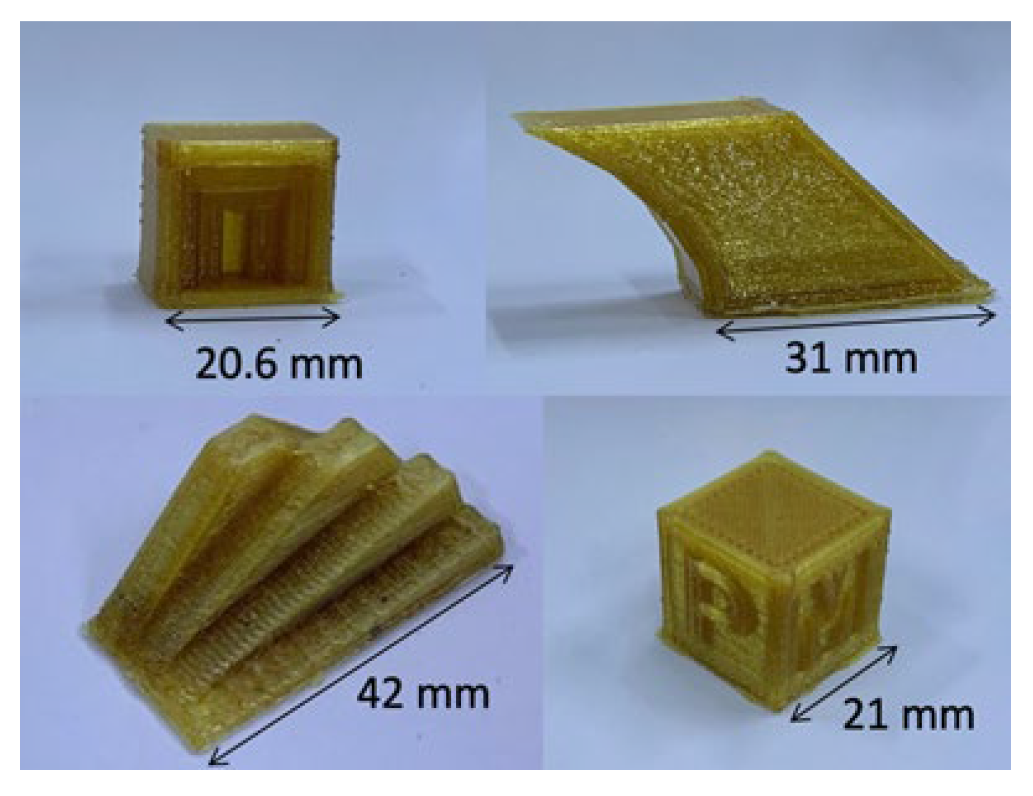
4.2. Warping Process Window

The sensitivity on the build surface temperature was run using a “warping test” to find the temperature that allows proper adhesion to the build surface and prevents warping. In every condition, a special adhesive designed for high-temperature materials production has been used. The test is carried out by printing a thin hexahedron with a given bed temperature and, after the printing phase, measuring the deformation by pushing one side on a flat table. The quantitative measure of warping is calculated as the difference in height between the two sides of a 70 mm long rectangular sample (the other two dimensions are 1.5 mm thickness and 15 mm width). If no warping takes place, this difference should be negligible. It was found that the least warping was obtained with the highest value of the variable in the investigated range: 210 °C (results are summarized in Table 4). It is therefore suggested to use a bed temperature Tb equal to or greater than 210 °C. In this test, the spacing between each condition is chosen large enough to notice in a clear and deterministic manner the results at different Tb. If the specimen were printed at temperatures closer to each other, the possibility of having not easy-to-interpret results would have been higher.

4.3. Cooling Power Process Window

For relatively tall geometries, a cooling fan can be used to reduce the thermal load brought to the sample from the extruded material and the heated nozzle.
Specifically designed test geometries were 3D printed, namely an “overhang test”, an “engraved cube test”, a “bridge test”, and a “staircase test” (Figure 2) to find an acceptable value of layer fan speed.
The most promising results have been obtained with the fan speed at 25% of its maximum power, having to overheat for lower power and delamination for higher power (Table 5). The use of the layer fan is dependent on the geometry to be printed. The fan is useful for relatively tall parts where the time required for printing one single layer is short; therefore, there is a risk of increasing part temperature layer after layer. On the contrary, heating instead of cooling can be used to reduce warping and improve inter-layer adhesion for flat and large geometries.

4.4. Improvement of Inter-Layer Adhesion

Some tensile test samples, printed flat on the deposition table (as in Figure 3), were printed with three different IR power levels (0%, 25%, and 50%) to determine the maximum power which does not overheat and degrade the material. The tests (Table 6) concluded that for values higher than 25%, the material starts to degrade and overheat; therefore, for good quality and strength, a power lower or equal to 25% should be employed.
In Table 7 the determined adequate thermal process parameters are summarized.

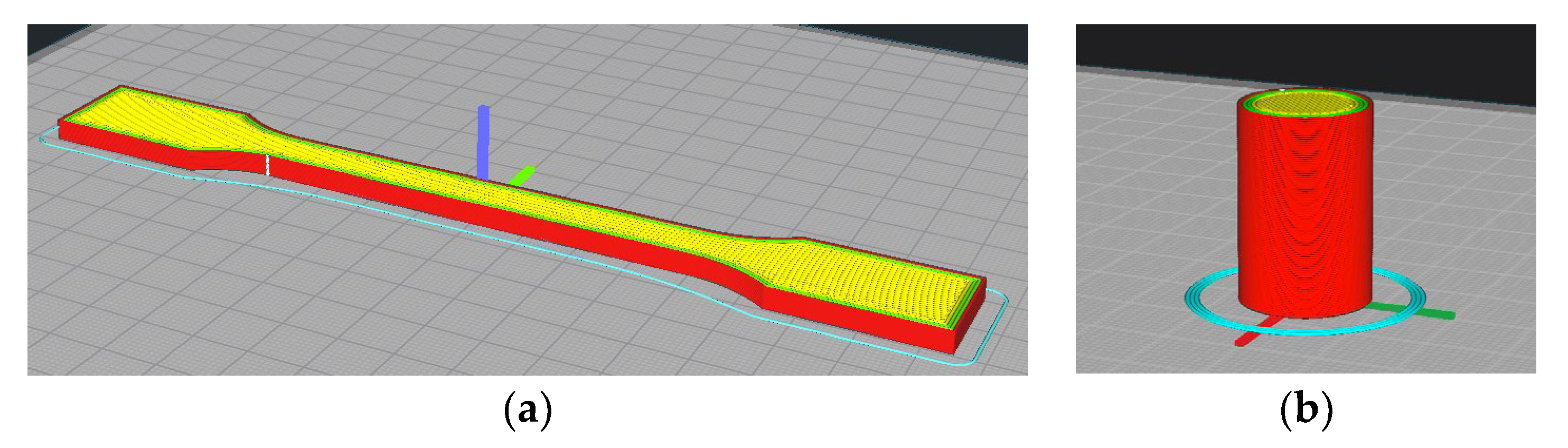
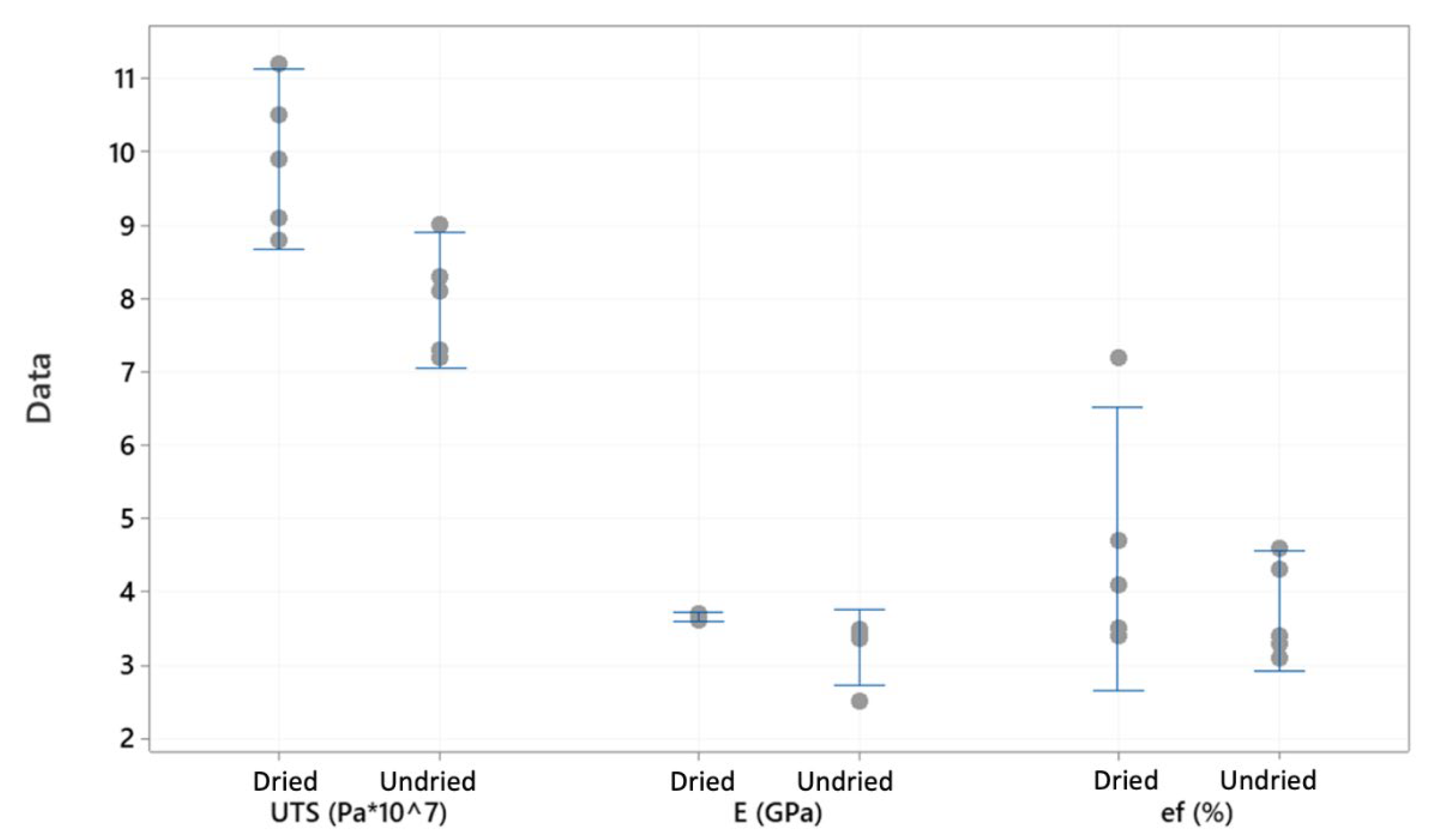
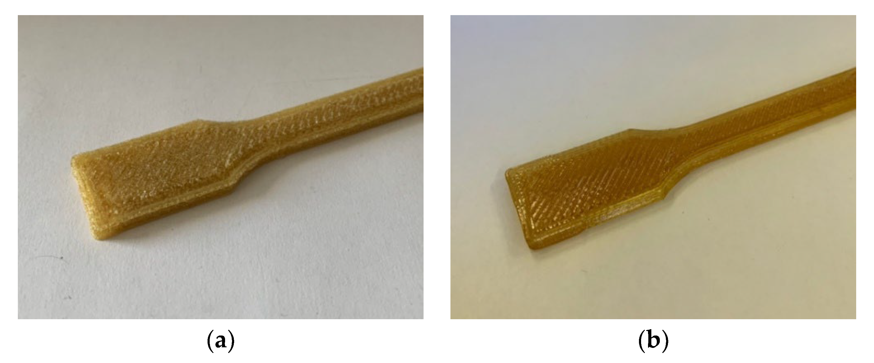
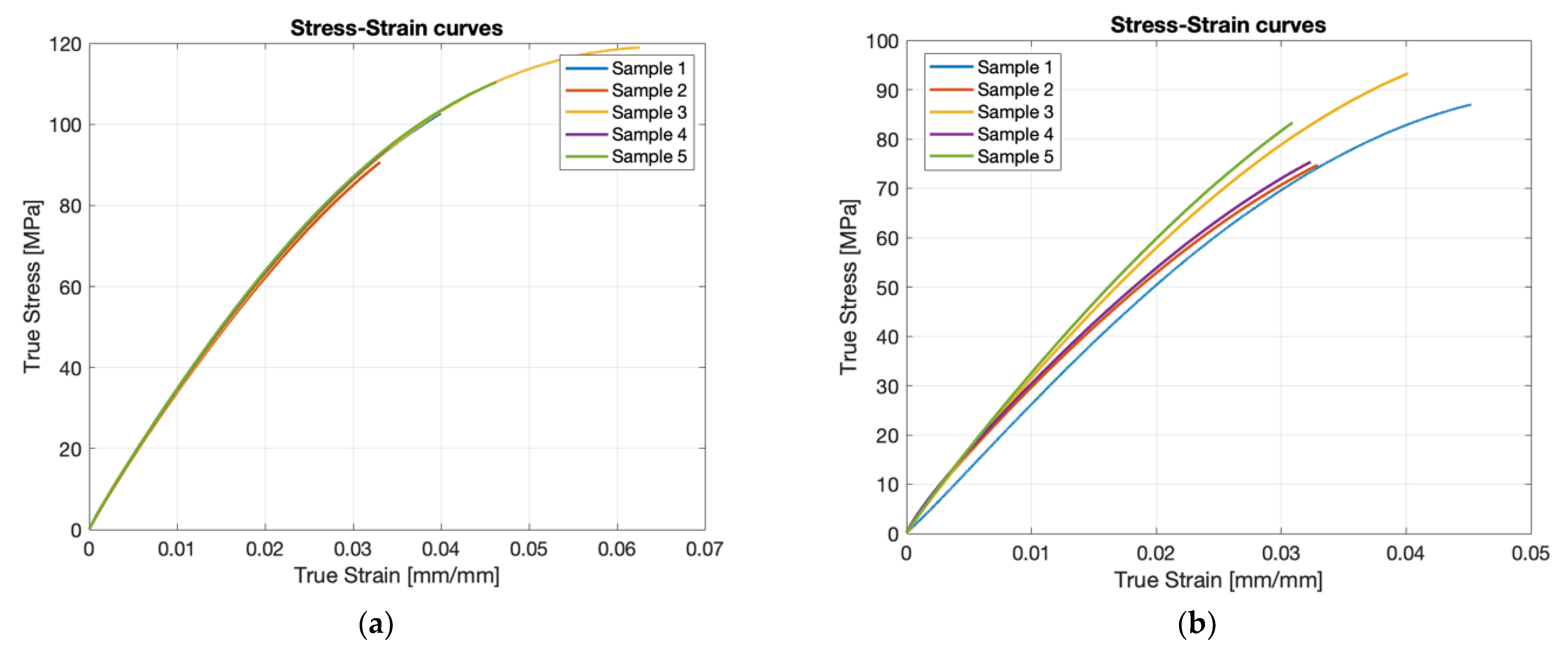
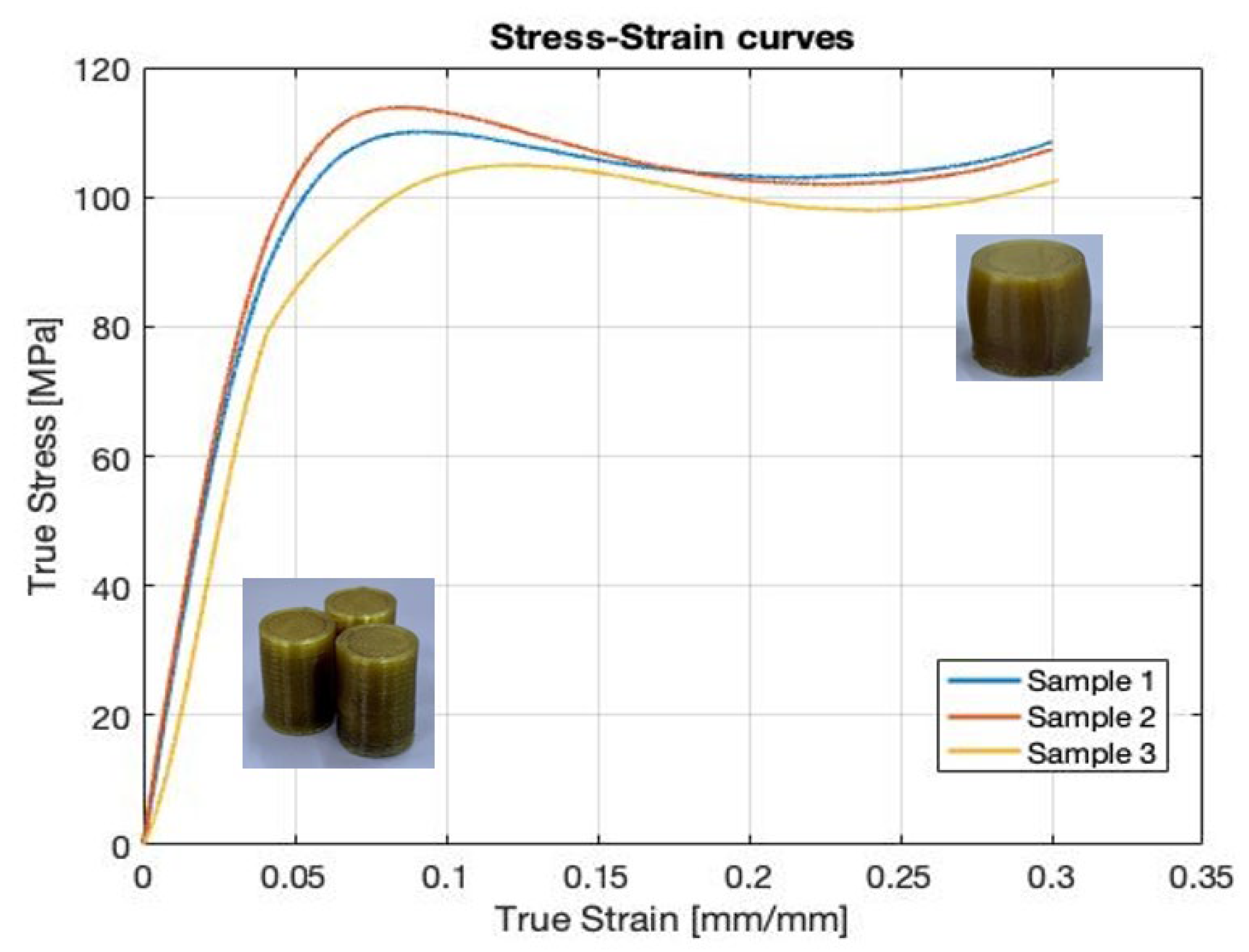
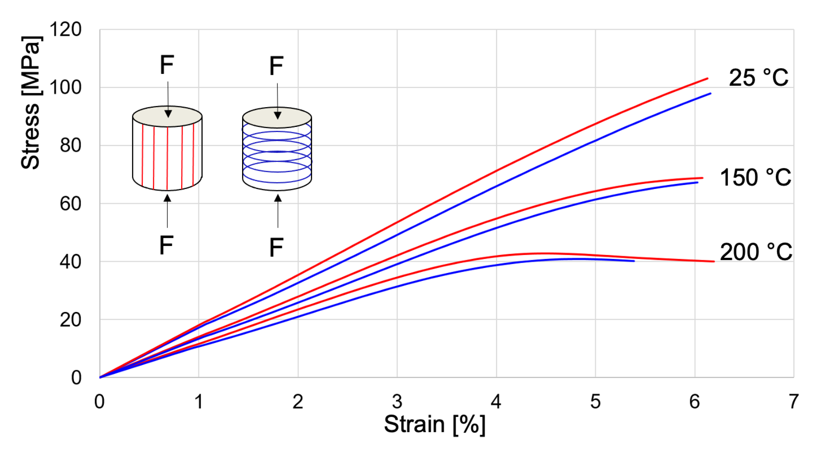
4.5. Mechanical Testing

Compression and tensile specimens have been printed with the thermal process parameters presented in Table 7 and with the kinematic parameters summarized in Table 2. These tests are intended to verify the mechanical properties of PEI 1000 printed components directly with pellets and compare them with the typical values of 3D printed FFF (Fused Filament Fabrication) samples and with injection molded ones, with data taken from the literature [22]. The tensile test specimen (Figure 3) has been designed according to ISO 527-2, specimen type 1A, with an overall length of 170 mm and a neck section of 10 mm × 4 mm. The compression test specimen follows ISO 604, with a diameter of 17 mm and L/D = 1.5 (Figure 3).
Tensile tests have been carried out with a deformation rate of 5 mm/s, according to the ISO 527 standard. The batch of samples tested included five partially dried samples, for which the material has been dried for a short time and left in a jar for a few weeks, and five adequately dried samples, produced with PEI pellets dried with a hot air drier for 16 h at 150 °C and printed in less than a week.
Jiang and his coworkers [33] suggested performing drying of PEI in a vacuum oven at 170 °C for 48 h to reduce moisture up to 0.02 wt% to avoid excessive bubbles in the extruded filament; therefore, trials with even higher drying temperature and drying time will be performed in future works. The possibility of drying in a vacuum and storing the dried material in containers under a vacuum should also be explored to reduce the possibility of moisture contamination, printing problems, and material properties degradation. The two conditions are intended to test the effects of moisture on mechanical performances, visual aspects, and microstructure. The printing parameters, environmental conditions, and temperatures are identical between dried and undried samples. As concluded by R. Zaldivar and his colleagues [28], in their study on ULTEMTM 9085, the presence of moisture in PEI can embrittle samples, generate porosities, modify the macrostructure generated by additive manufacturing and even modify the flow characteristics.
In Table 8 and Figure 4 the results of respectively undried and adequately dried samples are presented, including the mean and standard deviation of the most significant results, such as peak stress UTS, elastic modulus E, and strain at break ef (evaluated according to the ISO 527 standard). Stresses and strains reported in Table 8 are engineering values, not considering the reduction of section during tensile testing.
The dried samples unsurprisingly exhibit better properties. The dried samples showed, just after printing, a better aspect, with better dimensional and geometrical stability and translucent amber color, while the samples containing moisture showed opaque and lighter color and dimensional and geometrical inaccuracies as well (Figure 5). The mean and standard deviation of the neck section both for dried and undried samples are presented in Table 9, showing the better dimensional stability of dried samples. In not fully dried samples, the moisture, as the material exits the nozzle, expands, thus increasing the volume of the bead and expanding the print in an X-Y direction, since in the Z direction, the nozzle and the deposition of the subsequent layer tend to contrast this behavior.
In Figure 6, the tensile curves for dried and undried samples are presented, confirming how the moisture content increases the dispersion of results and can significantly decrease the material’s mechanical properties. This result is in agreement with the ones obtained by Zaldivar and his coworkers [28], which controlled in a more precise way the moisture content of the material and showed how moisture content can affect Young’s modulus, elongation at fracture and UTS, and therefore, modifying the shape of the stress-strain curves.
Comparing the tensile strength obtained with PEI 1000 pellet additive manufactured specimen, injection-molded (IM) ones, PEI 9085 AM and PEI 1010 AM, the results obtained in this work show that AM from the pellet and with proper parameters can achieve a strength comparable to injection molded PEI 1000 (Table 10).
The compression tests were performed with 1 mm/s compression rate. Only three replicates have been tested through compression tests because the dispersion of the results was expected to be relatively low. The samples were produced with dried material and identical process parameters and temperatures for tensile specimens. In Table 11, the properties obtained from compression tests are presented, while in Figure 7, the compression stress-strain curves are shown. The test was considered finished for a true strain value of 0.3.
For low strain values (below a deformation of 5%), the tensile and compressive responses are quite similar. The compressive yield true stress obtained with ULTEM™ 1010 samples 3D printed by filaments in a previous study [10] was about 115 MPa, comparable with the present results, while the obtained elastic modulus in compression was about 1700 MPa, significantly lower than the present value.
The mechanical properties in compression are repeatable to a good extent, showing a high compression elastic modulus and yielding stress for being a commercial unreinforced polymer. Additive manufactured PEI 1000 is therefore suited as Rapid Tooling material, both for sheet metal forming and polymer injection molding, thanks to its high resistance in compression and in high-temperature environments.

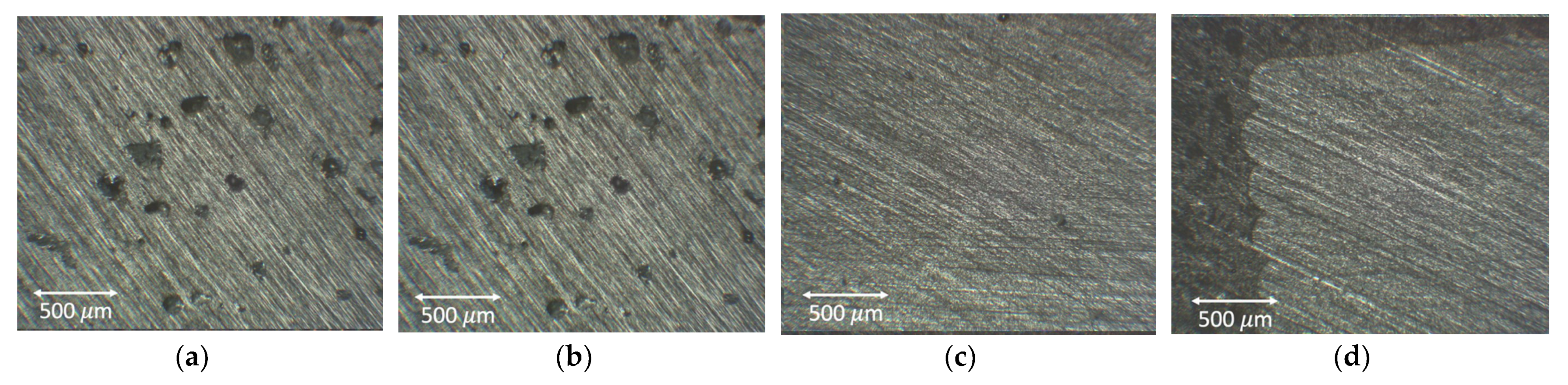
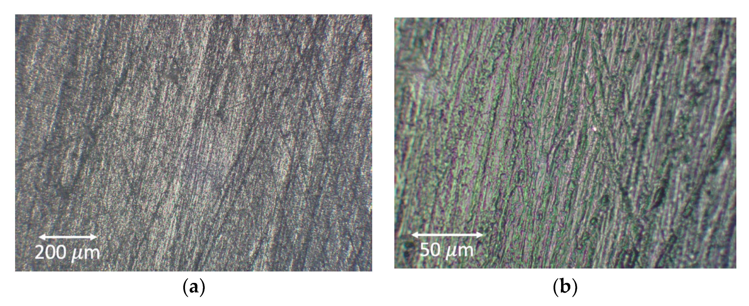
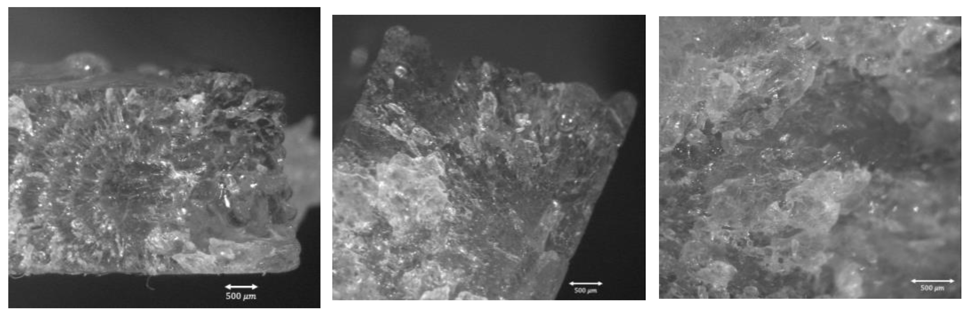
4.6. Microstructure of Additive Manufactured PEI

In order to understand and explain the differences obtained in tensile tests for dried and undried samples, the microstructure of the printed specimens has been analyzed with an optical microscope. The section is taken perpendicular to the test direction; it is, therefore, one of the neck sections with nominal dimensions 10 mm × 4 mm.
In Figure 8, the two conditions are compared by means of micrographic views, showing the presence of many voids due to moisture expansion during printing in the undried samples. This explains the lower mechanical properties of those samples and also the increased dispersion of results since moisture presence and expansion are stochastic phenomena.
In Figure 9, the microstructure of an adequately dried sample is shown, highlighting how the interlayer adhesion is very good since the surface is uniform and no visible voids are present. Moreover, the increased flow rate was also able to fill the geometrical voids left by the 45° alternate meander path of deposition and between walls and infill of the printed specimen, while maintaining good geometrical accuracy. At higher magnification, the typical aspect of solid polymers is noticeable, showing how the dried sample was properly printed.
The optical microscope, with magnification reduced to 10×, has been used to measure the actual road width of the dried tensile test samples. Four different samples have been used, six individual measurements have been taken from each sample for a total of 24 measurements. The road width, given a target infill% of 100%, should be equal to the hatch spacing h. The nominal hatch spacing is 0.80 mm, while the actually measured road width is 0.77 mm on average, with a standard deviation of 0.13 mm and an average error to the target value of 0.03 mm. The standard deviation over the mean value ratio, i.e., the coefficient of variation cov, is rather large: cov = 0.13/0.77 × 100 = 17%. This large variability is the consequence of many different sources of variation: the variability of flow rate and diameter of the extruded filament, the variability of temperature and viscosity, the variability of the actual printing speed in different locations onto the same layer, etc.
The fracture surface was analyzed with the optical microscope (Figure 10), highlighting how the fracture in tensile test samples was fragile with almost no deformation, the typical behavior of thermoplastic material tested at ambient temperature.

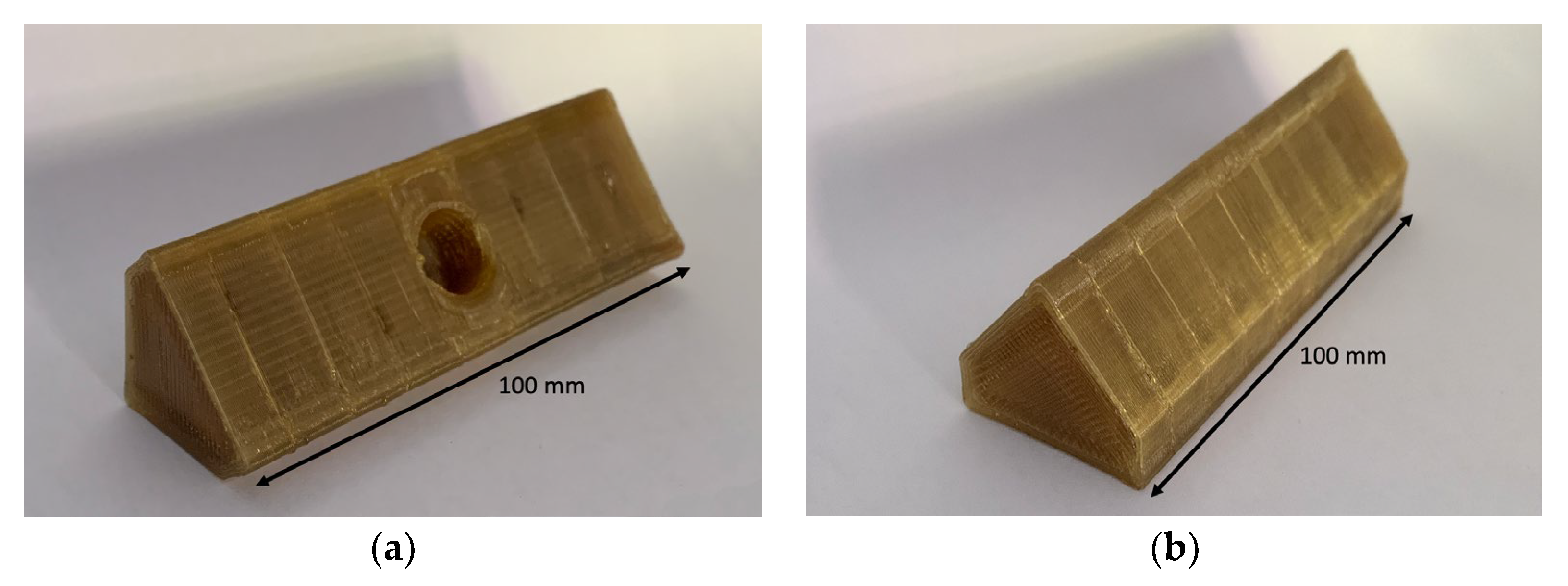
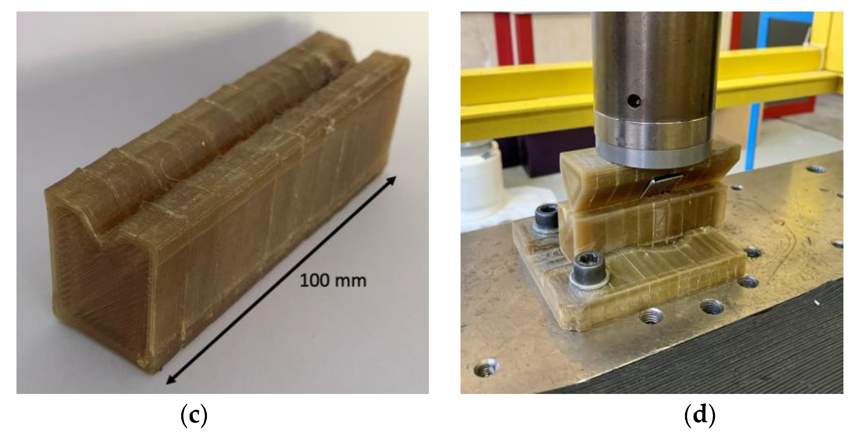
4.7. Rapid Tooling Test Case

To further assess the correctness of the printing parameters listed in Table 2 and Table 7, a demonstrative part has been 3D printed with these conditions. The parameters used include Tn = 380 °C, f = 0 %, IRp = 10%, v = 25 mm/s, h = 0.8, z = 0.25. The ones which differ from Table 2 and Table 7 are only IRp and f, which have been slightly modified according to the geometries which had to be produced. As stated in Section 1, one of the main applications of this polymer is the production of rapid tools, reducing cost and time for small batches produced by injection molding or sheet metal forming. This material would be particularly suited for both these applications thanks to its high mechanical strength under compression and its thermal resistance. For these reasons, a simple punch and die set for sheet metal forming has been produced. The toolset is intended to perform v-bending on thin metal sheets with thickness between 0.8 and 1.2 mm. The achievable angle is directly related to the stroke of the punch.
The die and tool have been designed in order to fit an MTS Alliance RF/150, which, being a mechanical testing machine, guarantees high stiffness and accuracy in position.
The two components have both been printed vertically and without any support in order to have good surface quality for the subsequent v-bending operation and limited angle deviation during subsequent bending operations, as shown in [45].
As highlighted in [10], the compression properties of an -manufactured specimen are better in the perpendicular direction for building one (Figure 11). Therefore, since this tool is expected to work under compressive loads, higher strength and elastic modulus should be achieved by printing the specimen vertically in order to have the compressive direction perpendicular to the building one.
The results of the printed objects after the removal of burrs are shown in Figure 12. The complete toolset after an experimental trial is also shown. The toolset was mounted on an Alliance RF/150 testing machine and showed no plastic deformation or fragile fractures upon bending a 0.8 mm car panel steel sheet.

4.8. Cost Analysis

In rapid tools, which must bear high compressive and shear stresses, a typical approach is to build parts with a target 100% infill density. The BUR (Build Up Rate) of the process can be estimated as the product of scanning speed v, hatch distance h, and layer height z:
B U R = v · h · z   m m 3 s
The nozzle extrusion temperature Tn and the BUR are the two main cost drivers of the process, along with the feedstock cost per kg. In this case, the Build Up Rate is BUR = 5 mm3/s, and the nozzle temperature is Tn = 380 °C. These experimental conditions are comparable to other values that can be found in the scientific literature: the typical BUR ranges from about 2 mm3/s with low-cost filament-based 3d printers (as in references [32,33] with ULTEM™ 1010 and 1000, respectively). The BUR can be increased to about 15 mm3/s (as in reference [46] with ULTEM™ 9085) with a high-end professional filament-based 3d printer.
With respect to costs, three different scenarios can be assumed according to the material and the type of machine used. Some reasonable and realistic assumptions can be made with respect to the costs of the material feedstock and the 3D printing machines. Let us assume that a low-cost 3D printer costs about 500 €, a high-end filament 3D printer costs about 200,000 €, and that the EFeSTO machine used in this paper costs about 100,000 €. For procurement of low quantities of feedstock (below 25 kg), the unit cost Cmat of ULTEMTM 1000 filament is about 270 €/kg [44], while the pellet material used in this paper costs 32 €/kg. The cost scenarios are summarized in Table 12 using the following cost model per unit volume:
C = C m a c h B U R + ρ C m a t
where ρ is the density of the material, Cmat is the material unit weight cost, Cmach is the machine unit time cost, which includes depreciation and energy. The labor and overhead costs are considered to be independent of the printing time and volume since they are only related to the process preparation and setup and can therefore be neglected if comparing different scenarios.
The total costs listed in Table 3 obviously depend on the assumed conditions; they cannot be taken as values with universal validity. However, the study indicates that a pellet extruder allows reducing the material cost almost by 90%. If considering the full printing cost, the proposed EFeSTO pellet extruder is very competitive with a high-productivity professional 3D printer

5. Conclusions

The most significant and innovative results obtained through this paper are summarized as follows.
The specially designed EFeSTO machine was able to print high-temperature materials such as PEI 1000 pellets with good quality and adequate mechanical properties.
It is possible to produce technical objects through additive manufacturing from PEI pellets, with lower cost compared to filament production and superior mechanical properties.
The experimental campaign showed how the thermal conditions in EAM affect the printed object quality. In general, the thermal conditions after extrusion (i.e., fan and IR power) should be controlled considering the specific geometry and orientation of the produced object. With a proper selection of the thermal variables both prior to and after extrusion, it is possible to obtain objects having mechanical properties comparable with injection molded components.
A good compromise in terms of quality and strength of the PEI parts can be achieved with 380 °C nozzle temperature, 210 °C bed temperature, 25% layer fan speed, and IR power at 10% (90 W).
Drying the PEI pellet feedstock material prior to production is absolutely required to achieve adequate results in terms of geometry and mechanical properties.

Author Contributions

Conceptualization, M.F., H.G. and M.S.; methodology, M.S.; software, H.G.; formal analysis, M.F.; investigation, M.S.; data curation, D.F.; writing—original draft preparation, M.F.; writing—review and editing, M.F., MS. and D.F.; All authors have read and agreed to the published version of the manuscript.

Funding

This research received no external funding.

Data Availability Statement

Not applicable.

Conflicts of Interest

The authors declare no conflict of interest.

References

  1. Srivastava, M.; Rathee, S. Additive manufacturing: Recent trends, applications and future outlooks. Prog. Addit. Manuf. 2021, 7, 261–287. [Google Scholar] [CrossRef]
  2. Mohanavel, V.; Ali, K.A.; Ranganathan, K.; Jeffrey, J.A.; Ravikumar, M.; Rajkumar, S. The roles and applications of additive manufacturing in the aerospace and automobile sector. Mater. Today Proc. 2021, 47, 405–409. [Google Scholar] [CrossRef]
  3. Joshi, S.C.; Sheikh, A.A. 3D printing in aerospace and its long-term sustainability. Virtual Phys. Prototyp. 2015, 10, 175–185. [Google Scholar] [CrossRef]
  4. Ng, W.L.; Chua, C.K.; Shen, Y.-F. Print me an organ! Why we are not there yet. Prog. Polym. Sci. 2019, 97, 101145. [Google Scholar] [CrossRef]
  5. Shaik, Y.P.; Schuster, J.; Shaik, A. A Scientific Review on Various Pellet Extruders Used in 3D Printing FDM Processes. OALib 2021, 8, 1–19. [Google Scholar] [CrossRef]
  6. Valino, A.D.; Dizon, J.R.C.; Espera, A.H., Jr.; Chen, Q.; Messman, J.; Advincula, R.C. Advances in 3D printing of thermoplastic polymer composites and nanocomposites. Prog. Polym. Sci. 2019, 98, 101162. [Google Scholar] [CrossRef]
  7. Das, A.; Chatham, C.A.; Fallon, J.J.; Zawaski, C.E.; Gilmer, E.L.; Williams, C.B.; Bortner, M.J. Current understanding and challenges in high temperature additive manufacturing of engineering thermoplastic polymers. Addit. Manuf. 2020, 34, 101218. [Google Scholar] [CrossRef]
  8. Gardner, J.M.; Stelter, C.J.; Sauti, G.; Kim, J.-W.; Yashin, E.A.; Wincheski, R.A.; Schniepp, H.C.; Siochi, E.J. Environment control in additive manufacturing of high-performance thermoplastics. Int. J. Adv. Manuf. Technol. 2022, 119, 6423–6433. [Google Scholar] [CrossRef]
  9. Byberg, K.I.; Gebisa, A.W.; Lemu, H.G. Mechanical properties of ULTEM 9085 material processed by fused deposition modeling. Polym. Test. 2018, 72, 335–347. [Google Scholar] [CrossRef]
  10. Farioli, D.; Strano, M.; Vangosa, F.B.; Zaragoza, V.G.; Aicardi, A. Rapid tooling for injection molding inserts. In Proceedings of the ESAFORM 2021, online, 14–16 April 2021. [Google Scholar] [CrossRef]
  11. Sabic. ULTEMTM Resin 1000 Global Datasheet. 2021. Available online: https://www.sabic.com/en/products/documents/ultem-resin_1000_global_technical_data_sheet/en (accessed on 11 November 2022).
  12. Sabic. ULTEMTM Resin 9085 Global Datasheet. 2022. Available online: https://www.sabic.com/en/products/documents/ultem-resin_9085_global_technical_data_sheet/en (accessed on 11 November 2022).
  13. Sabic. ULTEMTM Resin 1010 Global Datasheet. 2022. Available online: https://www.sabic.com/en/products/documents/ultem-resin_1010_global_technical_data_sheet/en (accessed on 11 November 2022).
  14. Salazar-Martín, A.G.; García-Granada, A.A.; Reyes, G.; Gomez-Gras, G.; Puigoriol-Forcada, J.M. Time-Dependent Mechanical Properties in Polyetherimide 3D-Printed Parts Are Dictated by Isotropic Performance Being Accurately Predicted by the Generalized Time Hardening Model. Polymers 2020, 12, 678. [Google Scholar] [CrossRef] [Green Version]
  15. Ouassil, S.; El Magri, A.; Vanaei, H.R.; Vaudreuil, S. Investigating the effect of printing conditions and annealing on the porosity and tensile behavior of 3D-printed polyetherimide material in Z-direction. J. Appl. Polym. Sci. 2022, 4, 38. [Google Scholar] [CrossRef]
  16. Kaynan, O.; Yıldız, A.; Bozkurt, Y.E.; Yenigun, E.O.; Cebeci, H. Electrically conductive high-performance thermoplastic filaments for fused filament fabrication. Compos. Struct. 2020, 237, 111930. [Google Scholar] [CrossRef]
  17. Yilmaz, M.; Yilmaz, N.F.; Kalkan, M.F. Rheology, Crystallinity, and Mechanical Investigation of Interlayer Adhesion Strength by Thermal Annealing of Polyetherimide (PEI/ULTEM 1010) Parts Produced by 3D Printing. J. Mater. Eng. Perform. 2022, 31, 9900–9909. [Google Scholar] [CrossRef]
  18. Parker, M.E.; West, M.; Boysen, A. Eliminating Voids in FDM Processed Polyphenylsulfone, Polycarbonate, and ULTEM 9085 by Hot Isostatic Pressing. Bachelor’s Thesis, South Dakota Schools of Mines & Technology, Rapid City, SD, USA, 2009. [Google Scholar]
  19. Gómez-Gras, G.; Pérez, M.A.; Fábregas-Moreno, J.; Reyes-Pozo, G. Experimental study on the accuracy and surface quality of printed versus machined holes in PEI Ultem 9085 FDM specimens. Rapid Prototyp. J. 2021, 27, 1–12. [Google Scholar] [CrossRef]
  20. Alexandre, A.; Sanchez, F.A.C.; Boudaoud, H.; Camargo, M.; Pearce, J.M. Mechanical Properties of Direct Waste Printing of Polylactic Acid with Universal Pellets Extruder: Comparison to Fused Filament Fabrication on Open-Source Desktop Three-Dimensional Printers. 3D Print. Addit. Manuf. 2020, 7, 237–247. [Google Scholar] [CrossRef] [Green Version]
  21. Post, B.K.; Lind, R.F.; Lloyd, P.D.; Kunc, V.; Linhal, J.M.; Love, L.J. The Economics of Big Area Additive Manufacturing. In Solid Freeform Fabrication; 2016; pp. 1176–1182. Available online: https://www.osti.gov/biblio/1295120 (accessed on 11 November 2022).
  22. Bagsik, A.; Schöppner, V.; Paderborn, K. Mechanical properties of fused deposition modeling parts manufactured with ultem*9085. In Proceedings of the 69th Annual Technical Conference of the Society of Plastics Engineers (ANTEC’11), Boston, MA, USA, 1–5 May 2011; pp. 1294–1298. [Google Scholar]
  23. Motaparti, K.P.; Taylor, G.; Leu, M.C.; Chandrashekhara, K.; Castle, J.; Matlack, M. Effects of Build Parameters on Compression Properties for ULTEM 9085 Parts by Fused Deposition Modeling. Solid Freeform Fabrication. 2016, pp. 964–977. Available online: http://utw10945.utweb.utexas.edu/sites/default/files/2016/078-Motaparti.pdf (accessed on 11 November 2022).
  24. Taylor, G.; Wang, X.; Mason, L.; Leu, M.C.; Chandrashekhara, K.; Schniepp, T.; Jones, R. Flexural behavior of additively manufactured Ultem 1010: Experiment and simulation. Rapid Prototyp. J. 2018, 24, 1003–1011. [Google Scholar] [CrossRef]
  25. Pandelidi, C.; Maconachie, T.; Bateman, S.; Kelbassa, I.; Piegert, S.; Leary, M.; Brandt, M. Parametric study on tensile and flexural properties of ULTEM 1010 specimens fabricated via FDM. Rapid Prototyp. J. 2021, 27, 429–451. [Google Scholar] [CrossRef]
  26. Gebisa, A.W.; Lemu, H.G. Influence of 3D Printing FDM Process Parameters on Tensile Property of ULTEM 9085. Procedia Manuf. 2019, 30, 331–338. [Google Scholar] [CrossRef]
  27. Padovano, E.; Galfione, M.; Concialdi, P.; Lucco, G.; Badini, C. Mechanical and Thermal Behavior of Ultem® 9085 Fabricated by Fused-Deposition Modeling. Appl. Sci. 2020, 10, 3170. [Google Scholar] [CrossRef]
  28. Zaldivar, R.; Mclouth, T.; Ferrelli, G.; Patel, D.; Hopkins, A.; Witkin, D. Effect of initial filament moisture content on the microstructure and mechanical performance of ULTEM® 9085 3D printed parts. Addit. Manuf. 2018, 24, 457–466. [Google Scholar] [CrossRef]
  29. Gilmer, E.L.; Anderegg, D.; Gardner, J.M.; Sauti, G.; Siochi, E.J.; McKnight, S.H.; Dillard, D.A.; McIlroy, C.; Bortner, M.J. Temperature, diffusion, and stress modeling in filament extrusion additive manufacturing of polyetherimide: An examination of the influence of processing parameters and importance of modeling assumptions. Addit. Manuf. 2021, 48, 102412. [Google Scholar] [CrossRef]
  30. Ding, S.; Zou, B.; Wang, P.; Ding, H. Effects of nozzle temperature and building orientation on mechanical properties and microstructure of PEEK and PEI printed by 3D-FDM. Polym. Test. 2019, 78, 105948. [Google Scholar] [CrossRef]
  31. Shelton, T.E.; Willburn, Z.A.; Hartsfield, C.R.; Cobb, G.R.; Cerri, J.T.; Kemnitz, R.A. Effects of thermal process parameters on mechanical interlayer strength for additively manufactured Ultem 9085. Polym. Test. 2019, 81, 106255. [Google Scholar] [CrossRef]
  32. Han, P.; Tofangchi, A.; Deshpande, A.; Zhang, S.; Hsu, K. An approach to improve interface healing in FFF-3D printed Ultem 1010 using laser pre-deposition heating. Procedia Manuf. 2019, 34, 672–677. [Google Scholar] [CrossRef]
  33. Jiang, S.; Liao, G.; Xu, D.; Liu, F.; Li, W.; Cheng, Y.; Li, Z.; Xu, G. Mechanical properties analysis of polyetherimide parts fabricated by fused deposition modeling. High Perform. Polym. 2018, 31, 97–106. [Google Scholar] [CrossRef]
  34. Zhang, Y.; Moon, S. The Effect of Annealing on Additive Manufactured ULTEM 9085 Mechanical Properties. Materials 2021, 14, 2907. [Google Scholar] [CrossRef]
  35. Djokikj, J.; Doncheva, E.; Tuteski, O.; Hadjieva, B. Mechanical properties of parts fabricated with additive manufacturing: A review of mechanical properties of fused filament fabrication parts. Mach. Technol. Mater. 2022, 16, 274–279. [Google Scholar]
  36. Kuo, C.-C.; Chen, W.-H.; Zhang, J.-W.; Tsai, D.-A.; Cao, Y.-L.; Juang, B.-Y. A new method of manufacturing a rapid tooling with different cross-sectional cooling channels. Int. J. Adv. Manuf. Technol. 2017, 92, 3481–3487. [Google Scholar] [CrossRef]
  37. Bagalkot, A.; Pons, D.; Clucas, D.; Symons, D. A methodology for setting the injection moulding process parameters for polymer rapid tooling inserts. Rapid Prototyp. J. 2019, 25, 1493–1505. [Google Scholar] [CrossRef]
  38. Kampker, A.; Triebs, J.; Kawollek, S.; Ayvaz, P.; Beyer, T. Direct polymer additive tooling—Effect of additive manufactured polymer tools on part material properties for injection moulding. Rapid Prototyp. J. 2019, 25, 1575–1584. [Google Scholar] [CrossRef]
  39. Strano, M.; Rane, K.; Farid, M.A.; Mussi, V.; Zaragoza, V.; Monno, M. Extrusion-based additive manufacturing of forming and molding tools. Int. J. Adv. Manuf. Technol. 2021, 117, 2059–2071. [Google Scholar] [CrossRef]
  40. Giberti, H.; Strano, M.; Annoni, M. An innovative machine for Fused Deposition Modeling of metals and advanced ceramics. MATEC Web Conf. 2016, 43, 03003. [Google Scholar] [CrossRef] [Green Version]
  41. Das, A.; Gilmer, E.L.; Biria, S.; Bortner, M.J. Importance of Polymer Rheology on Material Extrusion Additive Manufacturing: Correlating Process Physics to Print Properties. ACS Appl. Polym. Mater. 2021, 3, 1218–1249. [Google Scholar] [CrossRef]
  42. Mackay, M.E. The Importance of Rheological Behavior in the Additive Manufacturing Technique Material Extrusion. J. Rheol. 2018, 62, 1549–1561. [Google Scholar] [CrossRef]
  43. Strano, M.; Rane, K.; Vangosa, F.B.; Di Landro, L. Extrusion of metal powder-polymer mixtures: Melt rheology and process stability. J. Mater. Process. Technol. 2019, 273, 116250. [Google Scholar] [CrossRef]
  44. D4makers Shop ULTEM 1000. Available online: https://www.3d4makers.com/products/pei-ultem-1000-filament?variant=9817967591471 (accessed on 11 November 2022).
  45. Zaragoza, V.G.; Rane, K.; Strano, M.; Monno, M. Manufacturing and performance of 3D printed plastic tools for air bending applications. J. Manuf. Process. 2021, 66, 460–469. [Google Scholar] [CrossRef]
  46. Forés-Garriga, A.; Pérez, M.A.; Gómez-Gras, G.; Pozo, G.R. Role of infill parameters on the mechanical performance and weight reduction of PEI Ultem processed by FFF. Mater. Des. 2020, 193, 108810. [Google Scholar] [CrossRef]
Figure 1. Bottom view of the reflector, which holds 3 IR heaters in a triangular layout and fan duct.
Jmmp 06 00157 g001
Figure 2. 25% layer fan speed specimens. Top: left bridge test, right overhang test. Bottom: left staircase effect test, right engraved cube.
Jmmp 06 00157 g002
Figure 3. Printing orientation of sliced specimens for tensile (a) and compression (b) tests.
Jmmp 06 00157 g003
Figure 4. Tensile mechanical properties comparison of dried and undried samples; individual data and interval plots (95% confidence intervals or the mean value) are shown.
Jmmp 06 00157 g004
Figure 5. Pictures of undried (a) and dried (b) specimens.
Jmmp 06 00157 g005
Figure 6. Tensile stress-strain curves for dried (a) and undried (b) materials.
Jmmp 06 00157 g006
Figure 7. Compression stress-strain curves.
Jmmp 06 00157 g007
Figure 8. Microstructure of the tensile specimens, (a,b) are undried, (c,d) are dried. (a,c) images are taken in the center of the section, while (b,d) are taken on the side, with the ends of the layers visible. The left images (i.e., undried), both in the center and side of the section, show voids with different dimensions, up to 0.3 mm, produced by the expansion of moisture during extrusion.
Jmmp 06 00157 g008
Figure 9. Microstructure at different magnifications of an adequately dried sample; a uniform and continuous structure visible.
Jmmp 06 00157 g009
Figure 10. Fractured surface of the tested tensile samples.
Jmmp 06 00157 g010
Figure 11. Compressive engineering stress-strain plot with different building orientations and testing temperatures of 3D printed ULTEMTM samples.
Jmmp 06 00157 g011
Figure 12. 3D printed punch after removal of burrs with pliers; in (a) the side of the punch which is connected to the machine ram is shown; in (b) the active side of the punch is shown; 3D printed die (c), complete 3D printed tooling set (d) after post-processing with sandpaper and Dremel, mounted on the MTS machine (the bent sheet metal is also shown).
Jmmp 06 00157 g012aJmmp 06 00157 g012b
Table 1. ULTEM™ grades properties comparison [11,12,13].
Grade908510101000
Tensile Stress, yield, 50 mm/min (ISO 527) [MPa]94110110
Tensile Modulus, 1 mm/min (ISO 527) [MPa]285032003200
Vicat Softening Temp, Rate B/50 [°C]173211211
Oxygen Index (LOI) (ASTM D2863)49%44%47%
Density (ISO 1183) [g/cm3]1.341.271.27
Izod Impact, notched 80 × 10 × 4 +23 °C (ISO 180/1 A) [kJ/m2]1056
Table 2. Kinematic process parameters for a 0.6 mm nozzle diameter.
ParameterValue
Flow ratio1.1
1° Layer Speed10 mm/s
Other Layers Speed v25 mm/s
1° Layer Height0.4 mm
Other Layers Height z0.25 mm
Hatch Spacing h0.8 mm
Number of Perimeters3
Raster Angle+45°/−45°
Table 3. Printing temperatures.
ParameterValue
Plasticization Temp. Tp355 °C
Extruder Temp. Ti330 °C
Nozzle Temp. Tn380 °C
Table 4. Bed temperature sensitivity analysis results; warping is measured as the difference in height between the two sides of a 70 mm long rectangular sample.
Warping Test123
Bed Temp. Tb (°C)110160210
AccomplishedJmmp 06 00157 i001Jmmp 06 00157 i002Jmmp 06 00157 i003
warping (mm/mm)11/703/700/70
NotesSignificant warpingSlight warpingNo warping
Table 5. Layer fan speed sensitivity analysis results.
123
Layer Fan Speed f0%25%50%
Overhang TestJmmp 06 00157 i004Jmmp 06 00157 i005Jmmp 06 00157 i006
NotesSlight overheatingAdequateStrong Delamination
Engraved CubedJmmp 06 00157 i007Jmmp 06 00157 i008Jmmp 06 00157 i009
NotesSlight overheatingAdequateStrong Delamination
Bridge TestJmmp 06 00157 i010Jmmp 06 00157 i011Jmmp 06 00157 i012
NotesStrong overheatingAdequateSlight Delamination
Staircase Effect TestJmmp 06 00157 i013Jmmp 06 00157 i014Jmmp 06 00157 i015
NotesStrong overheatingAdequateProbable Delamination
Table 6. IR power sensitivity analysis results.
Replica123
IR power % IRp02550
AccomplishedJmmp 06 00157 i016Jmmp 06 00157 i017Jmmp 06 00157 i018
NotesGood lookingAdequateOverheating
Table 7. Thermal process parameters summary.
ParameterValue
Plasticization Temperature Tp355 °C
Extruder Temperature Te330 °C
Nozzle Temperature Ti380 °C
Bed Temperature Tb210 °C
Layer Fan Speed f25%
IR power IRp10%
Table 8. Mechanical tensile properties of dried and undried samples.
Condition Young’s Modulus E [MPa]Peak Stress UTS [MPa]Strain At Break ef [%]
driedMean3661.699.04.6
Std. Dev50.59.91.5
COV1.37%10%32.60%
undriedMean3243.279.83.7
Std. Dev413.37.50.7
COV12.74%9.39%18.91%
Table 9. Neck section dimensions of dried and undried specimens.
DriedUndried
Thickness [mm]Width [mm]Thickness [mm]Width [mm]
Mean3.6210.273.7410.770
Std. Dev0.060.070.060.33
COV1.74%0.66%1.58%3.03%
Table 10. UTS of different PEI grades produced by AM or IM. Values should be intended only as general reference values since production parameters, conditions, and geometries are different among various sources, and therefore, cannot be directly compared.
MaterialMean UTS [MPa]Reference
PEI 1000 IM110[11]
PEI 1000 pellet AM99[present work]
PEI 1000 filament AM104[33]
PEI 1000 filament AM105[44]
PEI 1010 filament AM94[25]
PEI 9085 filament AM81[22]
Table 11. Mechanical compression test properties.
Young’s Modulus [MPa]Yield True Stress [MPa]
Mean2649109.6
Std. Deviation276.34.5
COV10.4%4.1%
Table 12. Cost scenarios, excluding the labour and overhead costs.
Type of MachineULTEMTM 1000
Feedstock
BUR   [ m m 3 s ] Material   Cost   C mat [ k g ] Machine   Use   Cost   C mach   [ h ]   Total   Cost   C   [ c m 3 ]
Low-cost 3d printerfilaments22700.20.37
EFeSTOpellets53210.00.60
High-end 3d printerfilaments1527021.70.74
Publisher’s Note: MDPI stays neutral with regard to jurisdictional claims in published maps and institutional affiliations.

