1. Introduction
Drones have generated a great deal of interest in recent years in both the military and civilian sectors because of their enormous potential for applications in reconnaissance, photography, transportation, rescue, and other areas [
1]. Currently, there are two main types of common drones: fixed-wing drones and rotorcraft drones. Both types have their own advantages and limitations. Fixed-wing drones have more obvious advantages in terms of cruising speed, payload, and flight range and duration, but they are constrained by take-off and landing fields and flight velocity. Rotorcraft drones, on the other hand, have no site limitations and have hovering capability, which gives them great flexibility; however, their flight speed and range are much lower than those of fixed-wing drones [
2,
3]. Therefore, fixed-wing vertical take-off and landing (VTOL) drones, which combine the advantages of the two types of drones, have a wide range of development prospects and have now become a popular research topic [
3,
4,
5,
6]. Various designs have been proposed for this type of drone, commonly including tilt-rotor [
7,
8], tilt-wing [
9,
10], tail-sitter [
11,
12] and compound VTOL [
13,
14].
VTOL drones have two primary modes of flight: multi-rotor flight mode and fixed-wing flight mode. These two modes of flight are connected by a transition mode, which usually persists only for a short period of time. In terms of flight control, the difficulties of transition control for VTOL drones have long been the focus of researchers due to their high dynamic uncertainty and the serious aerodynamic interference between rotors and wings [
15,
16,
17,
18,
19,
20,
21,
22,
23]. Yeo et al. [
24] proposed a gain-scheduled altitude control method to ensure stable transitions with minimal altitude changes, and this strategy is effective in allowing drones to maintain stability and altitude accuracy in transition modes. Liu et al. [
25] designed a unified six degrees of freedom (6-DOF) nonlinear control strategy using the Incremental Nonlinear Dynamic Inversion (INDI) method for the control during transitions, which effectively manages the complex dynamics of the transition maneuvering without the need to change the control logic. Zhao et al. [
26] transformed the transition strategy design problem into an optimal control problem with constraints, while the Gauss pseudospectral method (GPM) was employed to transform and solve the problem, effectively balancing the relationship between transition time, control inputs and attitude stability. Yuksek et al. [
27] designed a low-altitude flight control system based on an adaptive dynamic inversion method, using reinforcement learning methods to provide safety and energy efficiency during the transition flight phase, which improves the adaptability and efficiency of transition management for drones in complex urban environments. Dickeson et al. [
28] designed a robust
control method based on the conversion of a linear parameter variation model, which improves the robustness of the system under unmodeled dynamic conditions. Ye et al. [
29] proposed a soft transition mode using a control law that consists of implicit nonlinear dynamic inversion (NDI) and incremental nonlinear dynamic inversion (INDI). This approach improves robustness, safety, and smoothness during transitions.
To the best of our knowledge, although there are many studies on the control of transition modes in VTOL drones, the vast majority of them only aim to complete the transition process quickly and stably, and no researcher has yet proposed the transition process as a common flight mode. However, as the missions that VTOL drones are required to perform become more complex, the drones will need to be used more frequently in low-speed flight situations, which are difficult for this type of drone to adapt to (when flying in multi-rotor mode, the drag may be too high and it may be difficult to reach the desired velocity. Conversely, when flying in fixed-wing mode, the velocity may be excessive). Therefore, we focus on the transition mode due to its suitability for low speed flight. From our perspective, routinizing the transition mode has the following potential:
The VTOL drones have a large portion of the flight speed envelope in between the multi-rotor and fixed-wing modes that is not being effectively utilized.
During transition mode, the VTOL drones can maintain a horizontal attitude at a relatively low speed without the tilting of the airframe required by rotorcraft. This feature has the potential for use in various applications, such as power system inspection, disaster search and rescue, and aerial photography.
Compared to rotorcraft, VTOL drones use fixed-wings to provide lift during transition mode, which reduces energy consumption to some extent.
This paper proposes the use of the transition mode of a compound VTOL drone as a third common flight mode, alongside multi-rotor and fixed-wing modes. This mode will be referred to as the hybrid mode. The main contributions of this paper are outlined below:
We routinize the transition mode of a compound drone (meaning that the transition mode is used as a mode that works continuously for an extended period of time), propose the hybrid mode, and design its flight logic.
Combining the flight characteristics of the drone in hybrid mode, we establish its 6-DOF dynamics model in detail, and completely design the corresponding control strategy and controllers.
A method is proposed to identify the fixed-wing lift parameters of this type of drones in hybrid mode. Conventional wind tunnel tests are particularly costly and are generally not applied to small VTOL drones for economic reasons. The proposed method can effectively reduce the cost of identifying the fixed-wing lift and can be applied to a wide range of VTOL drones.
The proposed flight method is verified through simulation, and a compound VTOL drone prototype is built for real flight experiments.
The remainder of this paper is structured as follows: In
Section 2, the dynamic model of the system will be built. The control strategy and controllers design are overviewed in
Section 3. Simulations and experimental validation are presented in
Section 4 and
Section 5, respectively. Finally, conclusions and future works are drawn in
Section 6.
2. Modelling of the System
In this section, we introduce the flight control logic of the compound VTOL drone for hybrid mode, combine the motion characteristics of the drone to build its dynamic model in this particular mode, and describe the relevant parameter identification.
2.1. Hybrid Mode Control Logic
The power system of the drone in this work consists of two parts. One is the four multi-rotor actuators that generate vertical thrust, and the other one is the tail-thrust actuator located at the rear of the fuselage that generates forward thrust for the drone. All motor actuators are activated, and the control surfaces of the fixed-wing are made ineffective in hybrid mode.
As shown in
Figure 1 the flight control logic of the compound VTOL drone for hybrid mode is designed as follows:
Vertical motion: When the combined lift generated by the four multi-rotor actuators and the fixed-wing due to aerodynamic force is greater than the gravity of the drone, the drone ascends; otherwise, it descends. When the combined lift is equal to the drone’s gravity, the drone maintains its current altitude.
Forward motion: Compared to the multi-rotor mode, forward motion in hybrid mode is achieved by using the tail actuator to provide thrust rather than generating a specific pitch change to allow the multi-rotor actuators to provide forward thrust. In hybrid mode, the forward acceleration and deceleration of the drone are controlled by the rotational speed of the tail actuators, and the drone cannot move backward.
Lateral motion: Similar to a quadrotor, the lateral motion of the drone is achieved by the difference in rotational speed between the left and right multi-rotor actuators, causing the fuselage to roll and thus generate lateral thrust. Taking rightward movement as an example, the rotational speed difference causes the drone to roll. At this moment, the multi-rotor actuators create a rightward thrust. Simultaneously, due to the aerodynamic force, the fixed-wing also produces a component of rightward thrust, enabling the drone’s movement to the right. The leftward motion is the same.
Yaw motion: The four multi-rotor actuators generate a gyroscopic torque when they rotate. When the rotational speed of one pair of actuators increases while that of the other pair decreases, the gyroscopic torque rotates the fuselage. The rotational direction of the drone is opposite to that of the actuators whose rotational speed increases.
2.2. Dynamic Model
In the conventional transition mode, most VTOL drones only perform forward acceleration, so only the longitudinal model of the drone is usually considered [
30]. However, it is necessary to build a complete dynamic model of the drone in hybrid mode.
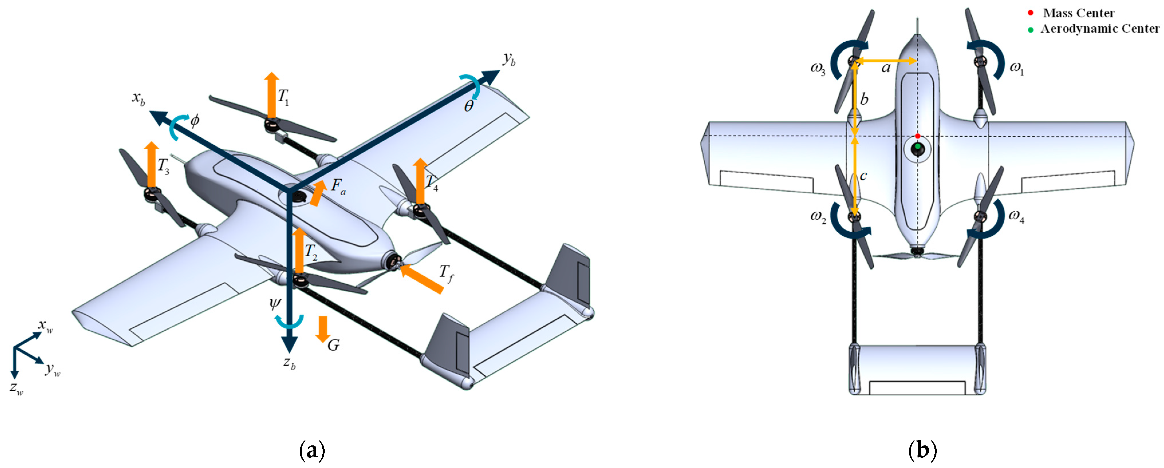
The modeling of drones is very complicated. In order to make the model simple and without losing its relevance, we consider the drone to be a rigid body. Therefore, the state variables describing its motion can be reduced to the position and velocity in the inertial frame, as well as its attitude represented by the body frame and angular velocity.
As shown in
Figure 2a, body frame
and North-East-Down (NED) inertial frame
are defined.
2.2.1. Position Dynamics Model
According to Newton’s second law, the positional dynamic equation of the drone in the inertial frame is as follows:
where
is the total mass of the drone,
is the resultant force,
and
are the position and velocity of the drone in the inertial frame, respectively.
The resultant force can be divided into the following parts: gravity
, collective thrust of the actuators
, aerodynamic force
, and disturbance force
. Therefore, Equation (2) can be written as:
Since the thrust of the actuators and the aerodynamic force are more intuitive and convenient in the body frame, we can further obtain:
where
is the transformation matrix from the body frame to the inertial frame, and the superscript
b denotes the vector in the body frame.
The collective thrust includes the thrusts of the multi-rotor actuators
and the tail-thrust actuator
, which can be written as:
where
is the rotation speed of the tail-thrust actuator,
is the rotation speed of each multi-rotor actuator,
is the tail-thrust actuator’s thrust coefficient which is influenced by the incoming airflow, and
is the thrust coefficient for the multi-rotor actuators. This paper considers the thrust coefficients as constants and the changes caused to the airflow effects as external disturbances.
The resultant aerodynamic force is traditionally decomposed into lift force and drag [
13]. We resolve it along the body frame into a lift force perpendicular to the fuselage, a lateral force, and a drag in the opposite direction of flight, as follows:
where the
is the airspeed,
is the air density, and
is the reference area of the wing. The aerodynamic coefficients
,
,
depend on the angle of attack
and sideslip angle
. In this work, we ensure that the fixed-wing control surfaces of the drone remain in neutral and do not engage in the control; therefore, the aerodynamic coefficients are not affected by them.
The dynamic equation of the drone also can be described in the body frame as:
where
and
are the velocity and rotation angular velocity in the body frame, respectively.
2.2.2. Attitude Dynamics Model
We assume that the rotational inertia matrix of the drone is
. According to the moment of momentum theorem, we can obtain:
where
is the resultant torque and
is the angular velocity in the inertial frame. According to the forces mentioned above, it can be known that the torques the drone receives include the actuators torque
, the aerodynamic torque
, and the disturbance torque
.
Since the drone is symmetrical about the
plane of the body frame, its inertia matrix can be written as:
Based on Coriolis’ theorem, in the body frame, the dynamics model of the drone can be written as:
The relationship between the Euler angular rate
and the body angular velocity is:
The actuators’ torque includes the thrust torque and gyroscopic torque generated by the multi-rotor and tail-thrust actuators. The thrust direction of the tail-thrust actuators passes through the mass center of the drone, so the thrust torque generated by the tail-thrust actuator is equal to 0. In addition, due to the wingspan of the drone’s fixed wing, its rotational inertia along the
is large. Therefore, we neglected the gyroscopic torque of the tail-thrust actuator. Then, the actuators’ torque can be expressed as:
where
,
and
are positive scalars characterizing the positions of the actuators with respect to the center of mass, as shown in
Figure 2b,
is the reverse torque coefficient of the multi-rotor actuator, and
is the thrust of each multi-rotor actuator.
The aerodynamic torque can be described as:
where
,
and
are the aerodynamic torque coefficients, respectively, while
is the wingspan and
is the mean aerodynamic chord.
2.2.3. Control Effectiveness Model
From the previous two subsections, the 6-DOF dynamic model of the compound VTOL drone in hybrid mode can be represented by Equations (4) and (11). For control in all degrees of freedom, we build the control effectiveness model of the drone. The inverse process of the control effectiveness model is the control allocation.
In hybrid mode, we only use the multi-rotor actuators and the tail-thrust actuator to control the drone while keeping the fixed-wing control surfaces in neutral. The required thrust and torque are controlled by the rotation speed of the actuators.
Based on Equations (5) and (13), the following matrix expression can be obtained:
2.3. Model Parameters Identification
Due to the influence of aerodynamic forces, the fixed-wing will always have a lift force in hybrid mode. The multi-rotor actuators need to constantly adjust thrust output to maintain the desired altitude. Since the lift generated by the fixed-wing changes with airspeed, the collective thrust of the multi-rotor actuators also needs to be adjusted with the airspeed. In order to improve the control accuracy and response speed for altitude control, it is necessary to identify the related parameters of the fixed-wing lift and multi-rotor actuators.
We assume that the drone is in a horizontal flying attitude and ignore interference forces. Expanding Equation (4) in the
direction, we can obtain:
where
and
are the unknown parameters.
Thrust throttle is often used in practice to control the collective thrust of the multi-rotor actuators. As shown in
Figure 3a, each actuator consists of an ESC, a motor, and a propeller. With the throttle command
and the battery voltage
, the actuators produce the collective thrust
. Obviously, thrust and throttle are positively correlated as
, which is easily obtained from a thrust test platform.
From Equation (17), when
we can obtain:
We set the desired vertical velocity to 0 and conduct multiple flight tests at different airspeeds. We keep the desired pitch angle at 0 to avoid thrust coupling and consider both the angle of attack and sideslip angle as 0, as we will mention in the control strategy of
Section 3. Then, we use a simple PID controller to control the vertical and forward velocities as shown in
Figure 3b, which can be described as:
When the height and forward velocity of the drone stabilize, throttle can be obtained from the autopilot. From Equation (18), we can compute the parameter .
The identification result will be shown in
Section 5.
3. Control Strategy and Controllers Design
This section first introduces the control strategy of the drone in the hybrid mode, and then details the design of the controllers.
3.1. Hybrid Mode Control Strategy
As mentioned in the control logic, in hybrid mode, only the multi-rotor actuators and the tail-thrust actuator are involved in the control of the drone, while the fixed-wing control surfaces are not activated in order to avoid control coupling. The fixed-wing acts as part of the lift generation, and the multi-rotor actuators supplement the lift for maintaining altitude.
In this mode, we adopt a control strategy similar to that of a rotorcraft. Except for the forward velocity, which is controlled through the tail-thrust actuator, the motion of the drone is mainly controlled by the four multi-rotor actuators. Therefore, to facilitate the subsequent controller design, we simplify the dynamics model in
Section 2.
We consider aerodynamic forces and torques, other than aerodynamic lift in the direction of the
, as external disturbances and incorporate them into the disturbance term. Then, Equations (4) and (11) can be written as:
where
is the lift represented in the body frame.
Afterward, in hybrid mode, we adopt a hierarchical control architecture that includes external loops (called position controller) and internal control loops (called attitude controller), as shown in
Figure 4.
In the position controller (
Figure 5a), in the vertical direction, we design the controller with feedforward, and in the horizontal direction we transform the coordinate frame into the heading frame for the controller design. The attitude controller (
Figure 5b) we designed is the same as in a common rotorcraft. However, we expect the pitch angle to always be set to 0 to keep the drone’s lift relatively stable.
It is worth mentioning that there is always a slow time-varying disturbance due to aerodynamic forces in the disturbance term in Equations (20) and (21), and since the controllers we designed are basically PID controllers, we need to consider anti-saturation for the integral term.
The detailed design of the controller is described in the following subsections.
3.2. Position Controller
We separate the position control problem into vertical altitude control and horizontal control. Since the drone has forward velocity at all times in hybrid mode, we disengage the horizontal position control and preserve the control of altitude. In horizontal control, only velocity control is available.
3.2.1. Altitude Control
The objective of the altitude control module is to define a desired vertical speed as an intermediate variable, as well as to control the height error and keep it converging to 0.
Define the saturation equation as:
We propose the following saturated proportional controller:
where
is the proportional control coefficient,
and
are the current and desired heights, respectively. With a North-East-Down convention for the inertial frame,
is the maximum climbing velocity and
is the maximum descending velocity.
In order to achieve the convergence of the vertical velocity
to the setpoint
, we need to obtain the desired vertical acceleration
. We propose the following PID controller with feed forward as:
where
,
and
are positive proportional, integral and differential gains, respectively, while
and
are the vertical acceleration constraints,
is the integral term and
is its saturation value, and
is the feedforward gain.
3.2.2. Horizontal Velocity Control
Because the forward velocity control and lateral velocity control of the drone use different control actuators, we design the horizontal velocity controller in the heading frame (
) as shown in
Figure 5c, where
and
coincide.
The horizontal velocity in the heading frame is:
To obtain the desired horizontal acceleration
, we design the PID controller for horizontal velocity as follows:
where
,
and
are PID gains,
and
are the horizontal acceleration constraints,
is the integral term and
is its saturation value.
In the control of forward velocity, we consider the influence of aerodynamic force, and thus focus on controlling the airspeed
. Therefore, we modify
in Equation (29) to be:
3.3. Thrust and Attitude Setpoints Calculation
3.3.1. Thrust
The calculation of thrust is divided into two parts. One is the forward thrust, which is derived from the forward acceleration performed by the tail-thrust actuator, and the remaining acceleration component is provided by the multi-rotor actuators.
The forward thrust can be easily obtained as:
where is
forward thrust factor. Because the desired pitch angle is equal to 0, we assume that the change in pitch angle is small, so the tail thrust is equal to the forward thrust
.
In order to calculate the desired collective thrust of the multi-rotor actuators, we first compute the hover thrust obtained from lift identification as:
where
is the fixed-wing lift obtained from the identification.
Then, we can observe the actuators’ vertical thrust as:
If we define the total desired acceleration vector as
, then we can calculate the multi-rotor collective thrust as:
3.3.2. Attitude Setpoints
As mentioned above, the desired pitch angle is always set to 0, the desired yaw angle is entered externally, and only the desired roll angle needs to be calculated.
The desired attitude is computed from the rotation matrix based on the vector of the desired
. The direction of
is the same as the direction of the collective thrust from the rotor actuator, which can be described as:
where
represents that
is expressed in the inertial frame.
Since the desired pitch angle is 0 and the direction of
is in the (
) plane, it can be written as:
From
and
we can obtain:
By the rotation matrix from the body frame to the inertial frame
we can obtain:
Since
, we can calculate:
3.4. Attitude Controller
The design of the attitude controller is the same as that of an ordinary rotorcraft. As shown in
Figure 5b, the center of mass and the aerodynamic center of the drone do not coincide. This results in the drone always being disturbed by the aerodynamic torque, which easily causes the integration saturation. For this reason, we designed a saturated cascade PID controller as follows:
where
is the angle proportional gain, while
,
and
are the angular rate PID gains and
is the integral term.
We then obtain the desired torque from Equations (12) and (21). Finally, we pseudo-inverse in Equation (16) to obtain the control allocation matrix, and then we can obtain the target rotation speed of each actuator.
5. Experiments
In this section, we describe a series of related experiments carried out for flight characterization of the compound VTOL drone in hybrid mode, as well as to validate the real flight performance of the designed control method.
5.1. Experiments Setup
As shown in
Figure 11a, a prototype VTOL drone is built for the following experiments. The fuselage of the drone is a VTBIRD composite frame. The multi-rotor actuators utilize T-motor F100 (2810) KV1100 motors, T-motor FPV 45A ESC, and HQ Prop 8045 propellers. The tail-thrust actuator is composed of a Dualsky XM2838EA KV600 motor, a HobbyWing SkyWalker 80A ESC, and a SAIL 12*6 propeller. A HOLYBRO Pixhawk V4 is used as the flight controller with PX4 v1.11 firmware [
31]. Sensors include a Holybro M9N GPS and a CUAV V5 digital airspeed meter. A 6S 8000 mAh 25C LIPO battery is used as an energy source. The related technical parameters of the prototype are shown in
Table 1.
5.2. Parameters Identification Experiment
5.2.1. Multi-Rotor Actuator Identification
To identify the multi-rotor actuator model, the thrust test platform is adopted as shown in
Figure 12a.
Under the same experimental conditions, different throttle commands are given in the range [0, 1], and the results are recorded when the actuator reaches a steady state. Using the MATLAB Toolbox [
32] to fit the experimental data, the identification results can be obtained, as shown in
Figure 12b.
From the result, it is relatively obvious that the throttle and thrust present a better relationship as a quadratic polynomial, which can be expressed as:
where
,
,
,
,
.
In practical control, we need the output throttle to control the actuators, so we also fit the equation to obtain the throttle from the thrust as:
where
,
,
,
,
.
5.2.2. Fixed-Wing Lift Identification
We use the method described in
Section 2.3 to identify the lift of the fixed-wing. The desired airspeeds from 0 to 9 m/s are divided into ten groups, with one identification group set up at 1 m/s intervals, and the experiment is repeated five times for each group of airspeeds. A total of 0 m/s can be read directly from the current hovering throttle. When the forward velocity and altitude are stabilized, the throttle of the multi-rotor actuators at that moment can be obtained. Then, the current fixed-wing lift can be calculated from Equations (18) and (46). We averaged the results of the repeated experiments for each group to get the lift of the fixed-wing at that airspeed. It should be noted that the identification experiments are conducted in nearly windless weather conditions. Therefore, it is assumed that the direction of airflow during flight is parallel to the drone’s flight direction. When acquiring the throttle, we ensure that the pitch angle of the drone is stabilized at 0 degrees, so the lift obtained from the identification is the lift of the drone when flying at 0 degrees of angle of attack.
Lift is related to airspeed as a quadratic polynomial, and we express the relationship as:
Fitting by the MATLAB Toolbox resulted in
,
,
, and the fitting result is shown in
Figure 13a.
From the results, it can be seen that, when the airspeed is less than 2 m/s, the fixed-wing produces almost no lift, and, at this point, it is sufficient to fly in multi-rotor mode. When the airspeed reaches 9 m/s, the throttle of the rotor actuator is reduced to less than 25%. To ensure the control margin of the drone, 9 m/s is the maximum forward flight velocity of this drone in hybrid mode. When the required flight velocity exceeds this velocity, the drone accelerates to reach the fixed-wing cruise velocity to switch to fixed-wing mode. Therefore, we define the forward flight velocity envelope for this drone in hybrid mode as 2–9 m/s.
With the identified lift, we can accurately calculate the required thrust compensation in the vertical direction for more stable altitude control. If the lift of the fixed-wing is not included in the calculation of the required thrust for the multi-rotor actuators, and the required hovering thrust is assumed to be essentially constant (similar to that of an ordinary rotorcraft), the vertical thrust control can only be provided through the PID controller output. This will result in a slow response and large errors in altitude control.
As shown in
Table 2, under the same conditions, the data obtained from the identification are included in the calculation of the vertical thrust, which reduces the maximum altitude error from 2.15 m to 0.96 m and the average error from 1.04 m to 0.06 m.
Figure 13b shows an example set of experimental comparisons under the same conditions. It can be clearly seen that using the proposed method makes the height control more stable and the error smaller. Without lift identification, the fixed-wing lift initially continues to increase as the drone accelerates forward, but the multi-rotor actuators’ thrust is not reduced in time. This results in the drone being unable to maintain the desired altitude, leading to unintended climbing. As the forward velocity stabilizes, the altitude controller gradually restores the drone to the desired altitude. Furthermore, the drone’s altitude is vulnerable to change if disturbed by airflow. When the identified lift is added to the thrust calculation, the altitude control exhibits a satisfying effect.
5.3. Enhancement of Yaw Torque
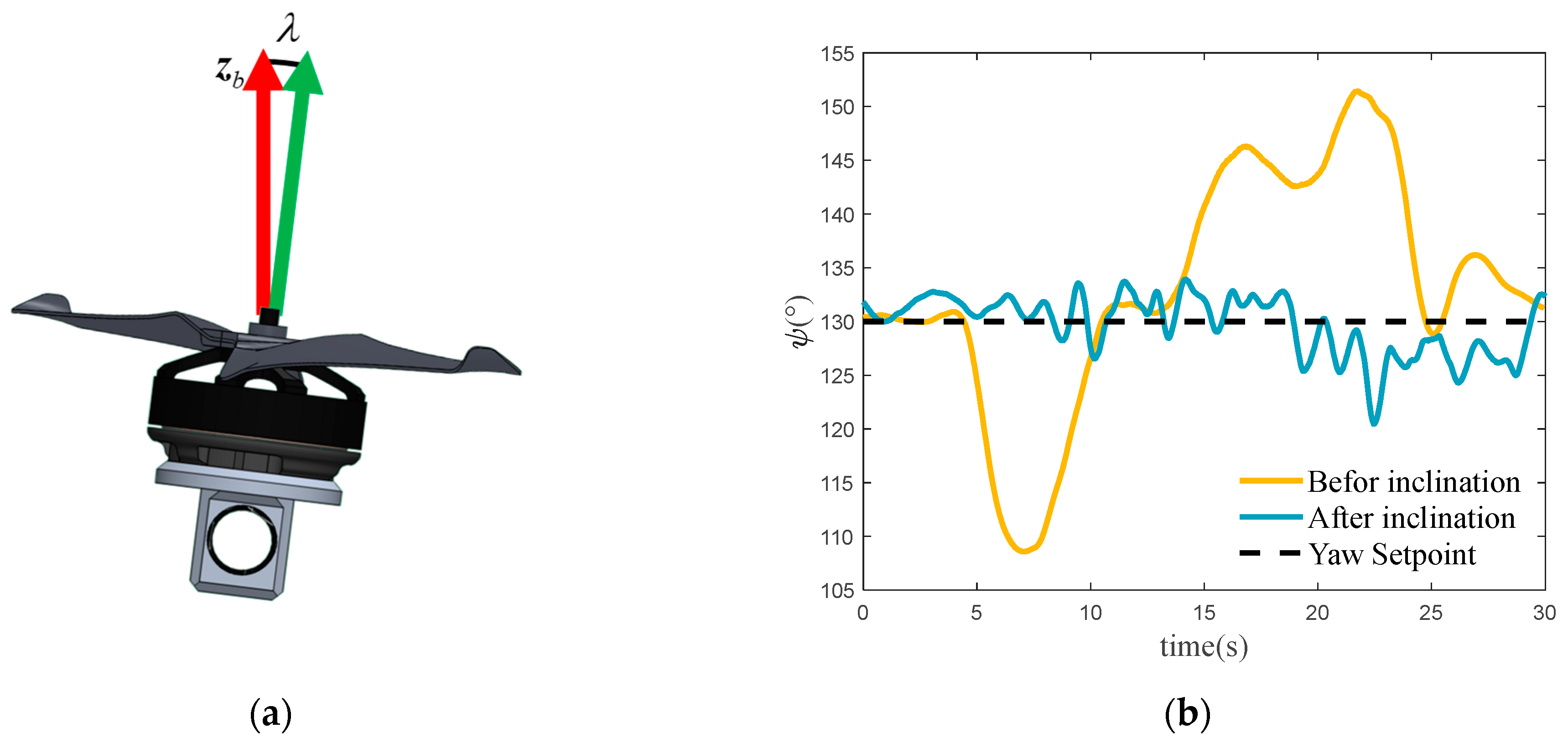
In actual flight, the drone may experience significant yaw disturbances in hybrid mode due to aerodynamic forces. Since the fixed-wing rudder is not activated, yaw control relies solely on the counter-torque generated by the rotational speed differences among the multi-rotor actuators, leading to limited control efficiency and a tendency for actuator saturation.
To address this issue in the actual flight of the prototype, we angled the multi-rotor actuators outward slightly, ensuring that the central axis of each actuator is not parallel to the
axis, as illustrated in
Figure 14a. Consequently, the thrust component of the actuators generates torque around the
axis, and the differences in rotational speed among the actuators can more effectively produce the yaw control moment, enhancing the yaw angle control efficiency and disturbance resistance. This approach is widely adopted in rotorcraft design.
For convenience, the tilt angle is set to 7 degrees. Subsequent flight tests under consistent experimental conditions showed a significant reduction in yaw angle error. As shown in
Figure 14b, one test conducted at a forward velocity of 5 m/s serves as an example. With the actuators mounted vertically, the maximum error reaches 21.4 degrees, and the average error is 8.5 degrees. After tilting the actuators outward, the maximum error is reduced to 9.5 degrees, and the average error to 2.3 degrees.
5.4. Real Flight Experiments
Since the aerodynamic model in the simulation environment described in
Section 4 is idealized, the aerodynamic disturbances encountered during actual flight are significantly more severe and unpredictable. To evaluate the real flight performance of the drone in hybrid mode, we replicate the experiments conducted in the simulation.
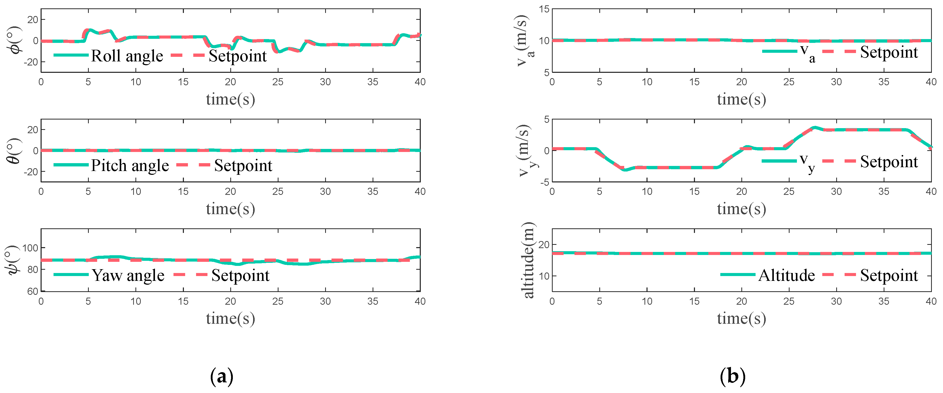
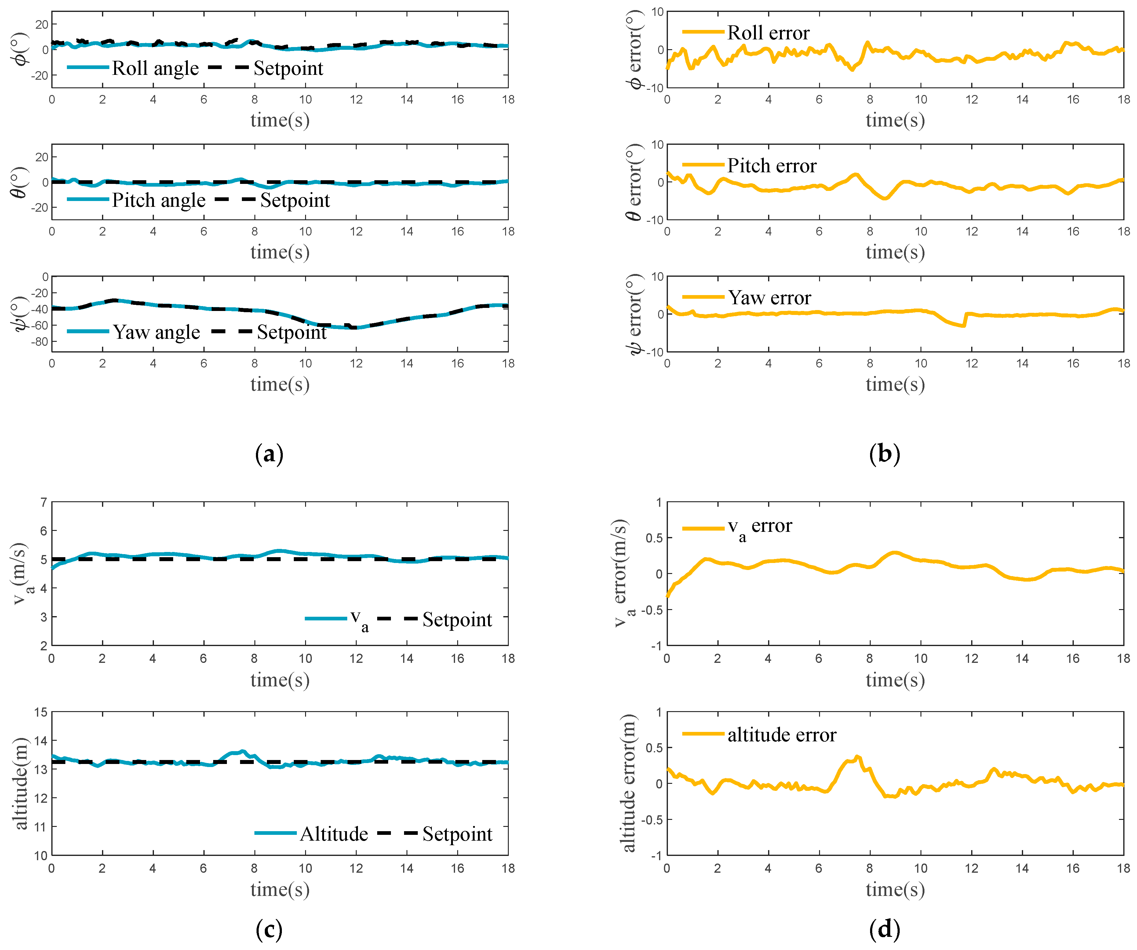
The drone is scheduled to gradually accelerate to the desired velocity and maintain horizontal flight in this case. According to the experimental results shown in
Figure 15, the drone is capable of accelerating to the desired velocity and maintaining a stable speed while keeping the altitude basically constant. Since the tail-thrust actuator has a practical response time, there is a delay of approximately 1 s during acceleration. During the first 5 s, the drone experiences slight fluctuations in attitude angles, especially in the yaw angle. These fluctuations are caused by the significant changes in aerodynamic forces during this time. The variation in the desired roll angle is due to the need for the drone to maintain a constant lateral velocity due to airflow disturbances. As the velocity stabilizes, the attitude angle also stabilizes. Furthermore, the increase in velocity results in an increase in fixed-wing lift, leading to a decrease in throttle output from the multi-rotor actuators. In an undisturbed environment, the multi-rotor actuators’ throttle is 50% when the drone is hovering. In the event of disturbance, the actuators need to be supplemented with some throttle to maintain altitude control and flight stability. In this case, when the velocity of the drone is low during acceleration, the lift provided by the fixed-wing is not significant, but the disturbance is relatively large, so there is a situation where the throttle of the multi-rotor actuators is increased. Only when a certain velocity is reached does the throttle of the multi-rotor actuators show a noticeable drop.
In this case, the drone adjusts its vertical velocity while maintaining its current forward velocity. The experimental results are presented in
Figure 16. The drone’s attitude angle remains stable throughout the process, with only minor fluctuations. It is worth mentioning that, when the drone has an upward flight velocity, the aerodynamic forces apply a sustained torque on the fuselage to keep it head down, causing the drone to always have a slight downward pitch angle, but with minimal effect on the flight. Since the drone experiences a vertical velocity change, at which point the altitude is unlocked, only the desired vertical velocity tracking is performed here. The effectiveness of the drone’s ability to track vertical velocity changes in hybrid mode is evident. As the drone moves vertically, the direction of incoming airflow changes, causing the airspeed to fluctuate and, consequently, the forward flight velocity of the drone.
The drone in this case will have a desired lateral flight velocity in hybrid mode flight, and the results are shown in
Figure 17. The experimental results demonstrate that the drone effectively tracks the required roll angle for controlling the lateral flight velocity. However, there is a significant deviation in the yaw angle during this period due to the coupling of the drone’s roll and yaw. During this period, the aerodynamic changes are more drastic, which has a considerable effect on the pitch angle. Overall, the drone’s attitude change remains within a relatively safe range. The forward velocity and altitude of the drone also fluctuate slightly as a result of the disturbance but remain relatively stable overall.
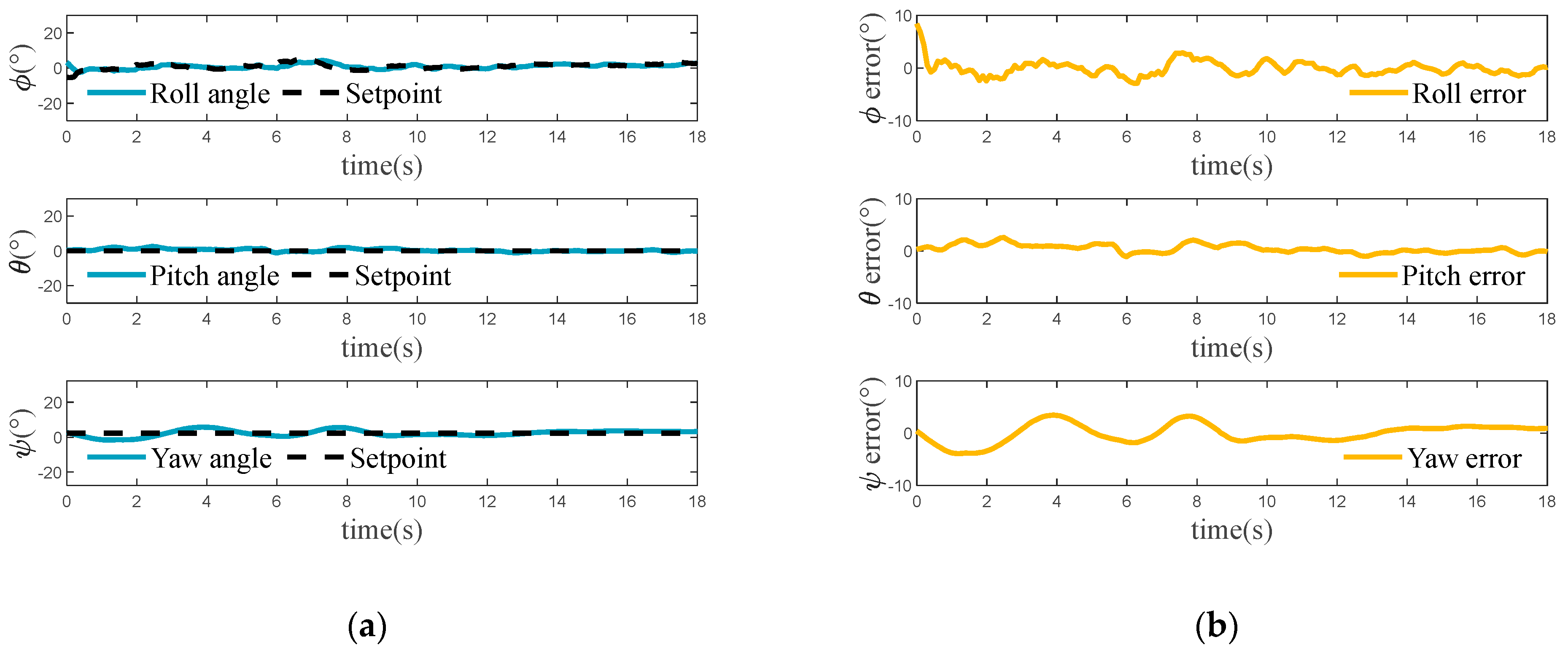
In this case, the yaw angle of the drone is altered during the flight. The experimental results in
Figure 18 illustrate that the yaw angle of the drone can be precisely controlled in hybrid mode. Although the coupling characteristics cause some deviation in the roll angle during yaw angle changes, the effect is less critical than for lateral motion. The pitch angle also varies as a result of the disturbance, but the impact is also relatively minor. The forward flight velocity of the drone exhibits an obvious error due to the constant variation in the incoming flow caused by changes in yaw angle. This significantly affects the accuracy of the flight velocity. The drone’s altitude remained stable throughout this period, and the fluctuations shown in the figure are due to airflow interference.
From the experimental results of the above cases, it can be concluded that the drone can meet the requirements of various motions during its hybrid mode flight, and the flight error is kept within a stable range. This indicates that the designed controllers and control strategy effectively implement the control of the drone’s hybrid mode flight and can satisfy the control requirements in the face of actual flight situations and changes in airflow.
5.5. Energy Consumption
In hybrid mode, the lift of the fixed-wing reduces the lift required from the multi-rotor actuators. This undoubtedly reduces the battery’s energy consumption to some extent. We measure the drone’s energy consumption within the flight velocity envelope of hybrid mode. The flight velocity is set at 1 m/s intervals, and the energy consumption is recorded after the velocity has stabilized. The average value is calculated from several experiments. To compare with the flight energy consumption in multi-rotor mode, we conduct the experiment in multi-rotor mode in the same way and under the same conditions. The maximum velocity of this drone in multi-rotor mode is 6 m/s. The flight energy consumption in fixed-wing mode cannot be compared here because the drone’s minimum flight velocity in fixed-wing mode exceeds 9m/s, making it unable to maintain flight status within the hybrid mode’s velocity envelope. Due to the high energy consumption of multi-rotor flight, it is almost certain that flying at cruising speed in fixed-wing mode will consume less energy than in hybrid mode, so fixed-wing mode energy consumption is not discussed here. The experimental result is shown in
Figure 19.
When the flight velocity is below 3 m/s, the reduction in output from the multi-rotor actuators is not appreciable due to the low lift of the fixed-wing. However, due to the effect of aerodynamic forces and the activation of the tail-thrust actuator, the drone requires more energy compared to multi-rotor mode. As the flight velocity and the fixed-wing lift increase, the energy consumption in hybrid mode decreases significantly. In contrast, the higher the flight velocity in multi-rotor mode, the higher the required pitch angle of the drone (as well as the significant aerodynamic drag of the fuselage and wings), resulting in a significant increase in the drone’s energy consumption. Therefore, flying in hybrid mode can reduce the energy consumption of this drone within a specific flight velocity range.
6. Conclusions and Future Work
This paper proposes the addition of a third common flight mode (hybrid mode) to compound VTOL drones. The hybrid mode routinizes the transition mode and extends the range of flight velocities and potential applications for this type of drone. We have built a detailed dynamics model for the motion characteristics of hybrid mode and designed a control strategy for this mode. Additionally, we have designed anti-saturation PID controllers for altitude, velocity, and attitude control to counteract aerodynamic disturbances. Furthermore, this study identifies the parameters of the drone’s fixed-wing lift and the thrust of the multi-rotor actuators to ensure accurate altitude control in hybrid mode. The feasibility of the control method has been verified through Gazebo simulation. A prototype has been built for real flight experiments, and the experimental results show that the control of hybrid mode flight can be effectively implemented and can meet the control requirements in actual flight situations. Finally, it has been proven that the use of hybrid mode flight can reduce the energy consumption of this type of drone during low-speed flight to some extent.
The next steps in the work are to improve the controllers used in hybrid mode to enhance the control of the drone. To enhance the control effectiveness, it may be worth considering incorporating a drone’s control surfaces into the control process. Moreover, hybrid mode will be implemented as a common mode for decision-making and path planning in drone missions.


