Article

Towards mmWave Altimetry for UAS: Exploring the Potential of 77 GHz Automotive Radars

1
Graduate School of Natural and Applied Sciences, Atilim University, Ankara 06830, Turkey
2
Department of Electrical and Electronics Engineering, Atilim University, Ankara 06830, Turkey
3
Department of Electrical and Electronics Engineering, Gazi University, Ankara 06570, Turkey
4
Department of Electronic Systems, Norwegian University of Science and Technology, 2815 Gjovik, Norway
*
Author to whom correspondence should be addressed.
Drones 2024, 8(3), 94; https://doi.org/10.3390/drones8030094
Submission received: 14 February 2024 / Revised: 8 March 2024 / Accepted: 9 March 2024 / Published: 11 March 2024

Abstract

:
Precise altitude data are indispensable for flight navigation, particularly during the autonomous landing of unmanned aerial systems (UASs). Conventional light and barometric sensors employed for altitude estimation are limited by poor visibility and temperature conditions, respectively, whilst global positioning system (GPS) receivers provide the altitude from the mean sea level (MSL) marred with a slow update rate. To cater to the landing safety requirements, UASs necessitate precise altitude information above ground level (AGL) impervious to environmental conditions. Radar altimeters, a mainstay in commercial aviation for at least half a century, realize these requirements through minimum operational performance standards (MOPSs). More recently, the proliferation of 5G technology and interference with the universally allocated band for radar altimeters from 4.2 to 4.4 GHz underscores the necessity to explore novel avenues. Notably, there is no dedicated MOPS tailored for radar altimeters of UASs. To gauge the performance of a radar altimeter offering for UASs, existing MOPSs are the de facto choice. Historically, frequency-modulated continuous wave (FMCW) radars have been extensively used in a broad spectrum of ranging applications including radar altimeters. Modern monolithic millimeter wave (mmWave) automotive radars, albeit designed for automotive applications, also employ FMCW for precise ranging with a cost-effective and compact footprint. Given the technology maturation with excellent size, weight, and power (SWaP) metrics, there is a growing trend in industry and academia to explore their efficacy beyond the realm of the automotive industry. To this end, their feasibility for UAS altimetry remains largely untapped. While the literature on theoretical discourse is prevalent, a specific focus on mmWave radar altimetry is lacking. Moreover, clutter estimation with hardware specifications of a pure look-down mmWave radar is unreported. This article argues the applicability of MOPSs for commercial aviation for adaptation to a UAS use case. The theme of the work is a tutorial based on a simplified mathematical and theoretical discussion on the understanding of performance metrics and inherent intricacies. A systems engineering approach for deriving waveform specifications from operational requirements of a UAS is offered. Lastly, proposed future research directions and insights are included.

1. Introduction

Accurate altitude estimation is paramount for ensuring the safety of unmanned aerial systems (UASs), particularly during the crucial phase of landing [1]. While various technologies contribute to this essential task, each method possesses unique limitations. Global positioning system (GPS)-aided attitude and the heading reference systems (AHRS) are prevalent in-flight navigation [2]. However, the slow update rate, typically at one pulse per second (PPS), poses challenges in catering to the rapid descent during the landing phase. Furthermore, the altitude data are referenced from the mean sea level (MSL), whereas autonomous landing necessitates altitude information above ground level (AGL). Alternative technologies such as light detection and ranging (LiDAR) systems also contribute to altitude determination. However, LiDAR systems present limitations in adverse weather conditions with poor visibility such as heavy precipitation, fog, or dust [3]. Barometric altitude estimation requires recurrently applying corrections to the readings due to temperature-induced variations in atmospheric pressure. Radar altimeters emerge as the optimal solution to UAS altimetry, addressing key limitations in other technologies by offering a high update rate and precise AGL altitude. By virtue of electromagnetic (EM) waves traversing through atmospheric hindrances chiefly unfazed, the resilience of the radar altimeter in adverse weather conditions further solidifies its role as an essential tool for ensuring the safety of UAS operations.
The two predominant waveforms employed in radar systems are Pulse Doppler and frequency-modulated continuous wave (FMCW) [4]. Continuous wave (CW) radars are limited to Doppler estimation only and, hence, do not find application in altimeters [5]. Pulse Doppler radar altimeters determine altitude by emitting short pulses of radio frequency (RF) energy and measure the round-trip delay for the echo to return from the surface of the ground. To avoid overlap between transmitted and received pulses, their duration must be shorter than the round-trip delay. Moreover, the time required for a solid-state switch to shift between the transmit and receive cycle is an essential consideration. Local oscillator (LO) inaccuracies further aggravate the timing situation, compelling a guard time interval. Collectively, these aspects require a long round-trip for the radar to function properly, hence compromising the minimum measurable altitude. Conversely, FMCW radars, owing to the simultaneous transmission and reception, are not strictly limited by a lower bound on altitude estimation. During the crucial landing phase, precise altitude estimation is vital until touchdown. In this context, FMCW radars emerge as the favored candidate. Moreover, continuous operation offers an additional benefit in terms of a low transmission peak power. This characteristic is significant for operations conducted in close proximity to the general public, as health authorities strictly regulate the transmission of peak power. Pulse Doppler radars typically operate with a duty cycle of 10%. Consequently, to attain the necessary average power, they are bound to transmit a higher peak power compared to FMCW radars.
Over the past decade, mmWave automotive radars were largely built on a relatively higher volume silicon germanium (SiGe) architecture with limited abstraction for a customized waveform design [6]. However, with the advent of integrated 45-nanometer (nm) radio frequency complementary metal oxide semiconductor (RFCMOS) technology, the microcontroller unit (MCU), digital signal processor (DSP), hardware accelerator (HWA), and RF front-end (RFFE) are all housed on the same chip now [7]. This breakthrough has opened massive opportunities in terms of highly flexible waveform design leading to a high performance in a miniature and cost-effective package. Initially designed for advanced driver assistance systems (ADASs) and limited only to high-end luxury cars, they now find widespread applications beyond the automotive domain [8]. Given the cost-effectiveness and wide availability, it is intrinsically appealing for application engineers and academicians to devise novel methods and techniques to stretch performance beyond hardware constraints. In the emerging proliferation of 5G networks and the associated interference in the universally allocated 4.2–4.4 GHz frequency band [9,10] for radar altimeters, it is imperative that we explore novel avenues without compromising the performance requirements for a stable UAS operation. To cater to the burgeoning need of the hour, the versatility of automotive radars can be extended to the realm of UAS altimetry. However, diverging from the identification of pedestrians and obstacles towards the estimation of backscattering from the ground surface, a major transformation of dynamics is expected. To the best of the authors’ knowledge, there is no dedicated minimum operational performance standard (MOPS) for radar altimeters of UASs. Accordingly, an adaptation from existing standards for commercial aviation is a reasonable approach given the largely similar application of radar altimeters in the landing stage of both platforms.
While a few products on the market have incorporated mmWave FMCW radars, there has been limited discourse in the literature. Given the sizable potential of automotive radars, characterized by their flexibility in waveform development, cost-effectiveness, and widespread availability, this study aims to bridge the existing gap in the literature. The focus of this investigation is to explore the feasibility of mmWave FMCW automotive radars for UAS altimetry. Holistically, in radar altimeters, the performance metrics mainly include the maximum and minimum measurable altitude, antenna beamwidth, and range accuracy. These metrics are intricately related, and a careful consideration of the trade-offs is necessary in order to meet the operational requirements of a versatile altimeter. To achieve the requisite performance, there are two aspects to the problem statement of adapting automotive radars for altitude estimation. The first is the theoretical and mathematical conversation encompassing performance metrics in tandem with hardware constraints. Subsequently, there is a need to highlight the challenges and requirements for the adaptation of existing and novel signal-processing algorithms for high-accuracy altitude estimation. In the context of limited reference studies, this study endeavors to initiate fresh discourse on the specific subject of mmWave altimetry encompassing an in-depth deliberation on performance metrics. To the best of the authors’ knowledge, a similar text is unreported. Furthermore, existing theoretical discussions on automotive radars often feature intricate mathematical expressions that may pose difficulty in understanding for emerging researchers. This article aims to address specific problem statements related to the application of mmWave radar technology in various scenarios. The primary focus revolves around developing a comprehensive understanding of intricate details crucial for specific applications. The methodology adopted involves an in-depth exploration of theoretical and mathematical aspects, aiming to provide a robust foundation for similar research endeavors. The outcome of applying this methodology has yielded valuable insights and knowledge, contributing to the refinement and enhancement of mmWave radar systems in a diverse context.
As a summary, the main contributions of this body of work are as follows:
  • A discussion on mmWave automotive radars as a novel and feasible avenue for UAS altimetry;
  • A simplified stepwise tutorial-themed mathematical and theoretical basis for understanding performance metrics;
  • An evaluation of backscattering from the ground surface using hardware specifications of a pure look-down mmWave automotive radar;
  • A rationalization of MOPSs for commercial aviation and a rationale for their adaptation to UASs;
  • A systems engineering approach for deriving radar specifications from operational requirements.
The remainder of the article is structured as follows: Section 2 provides an overview of related work. The state of the art, regulatory aspects, opportunities, and associated limitations in automotive radars are covered in Section 3. Section 4 offers the mathematical and theoretical basis of the performance metrics in FMCW radars. The rationalization of operational requirements and the resultant radar specifications are furnished in Section 5. The ensuing Section 6 amalgamates future research directions and potential hurdles. Section 7 presents the authors’ discussion with a summary of the contributions and the broader scope of the work. Finally, Section 8 concludes the article.

2. Literature Review and Related Work

mmWave radar technology has evolved significantly over the past couple of decades owing to the economies of scale as a consequence of the massive applications and use cases. Naturally, this has attracted the attention of researchers like any other technology. Profound theoretical and experimental studies have been reported in the literature beyond the initial scope of these radars, confined to automotive applications alone. Apart from expanding the scope of application, application engineers and academicians share a natural yearning for technologies that exhibit widespread applicability and cost-effectiveness. The focus of such studies is to transcend the inherent hardware limitations impeding the progress towards new avenues. The subsequent sections delve into these evolving trends and highlight the reference literature that propels such research endeavors. In the context of drone altimetry, comparable works are explored, aligning with the overarching theme. Finally, a succinct discussion on existing commercial radar altimeters is provided.

2.1. Innovative and Emerging Applications of mmWave Automotive Radars

Initially developed with a primary focus on automotive applications, mmWave radars have undergone a transformative journey over time, expanding their scope far beyond their original intent. The early stages of mmWave radar deployment predominantly centered around automotive functionalities. However, as the technology advanced, these radars found new frontiers in various domains, showcasing their versatility and adaptability. The evolution of mmWave radar technology has paved the way for a diverse range of applications, each with its unique set of challenges and opportunities.
The shift from a singular automotive focus to a multitude of applications highlights the agility and resilience of mmWave radar systems. The spectrum of applications spans from innovative realms such as 9 mm bullet radar cross-section (RCS) measurement to industrial domains like fluid level sensing and vital sign sensing. This proliferation of the technology into diverse sectors, including robotics, healthcare, and surveillance, signifies a remarkable transition. The adaptability of mmWave radar systems has not only broadened their utility but has also contributed significantly to advancements in various technological spheres. This expansion underscores the pivotal role these radars play in shaping a multifaceted landscape of applications, offering solutions that extend beyond the automotive realm. Table 1 lists a summary of related works.

2.2. Legacy and Contemporary Literature

The early use of radars was limited to military applications with a rich history of research and development. There have been many academic contributions in terms of textbooks dedicated to radar concepts and theory [21,22]. These resources offer a comprehensive coverage of the terminologies, fundamental principles, and algorithms, as well as frameworks for diverse types of radar waveforms and systems. Nevertheless, with the recent advancements in the field of automotive radars such as mmWave time division multiplexing multiple-input multiple-output (TDM-MIMO) [23], it is more appropriate and convenient to consult surveys and state-of-the-art review articles for an informed literature review [24,25,26]. Such works offer stimulating discussions on trends in the industry and the direction of research moving forward. Nonetheless, such reviews are devoid of depth and focus on the breadth of the research. On the other hand, concise instructional materials, emphasizing implementation details and practical facets, are presently being disseminated by manufacturers of mmWave radars. These resources are presented in the form of whitepapers and application notes intended for application engineers [27,28,29]. They offer a basic level of understanding from the perspective of product development with restricted introductory content and limited experimental work.
More recently, researchers have presented dissertations that delve into the intricate details of mmWave radars tailored for specific applications. The theoretical and mathematical nuances expounded in these works establish a substantial repository, offering valuable insights for similar endeavors to draw upon. In line with the aim of this work, the notable dissertation in [30] stands as a testament to stretching the boundaries of automotive radars for applications beyond conventional constraints. The cited work put forth the basis for the resolution of velocity ambiguity well beyond the maximum measuring capacity of automotive radars. Likewise, a consolidated theoretical and practical framework for the applicability of mmWave radars for vital signs application was offered in [31]. Such works lay the groundwork for exploring the untapped potential of automotive radars. This article aims to coalesce the strengths of the existing forms of literature and fill the looming gap. There is an evolving need to present a tutorial-themed piece of literature to equip the impending and enthusiastic researchers to better understand the theoretical aspects of cutting-edge technologies. To combine the strengths of the available spectrum of the literature, the theoretical basics have been embraced from legacy textbooks. Application notes were consulted for a better understanding of the hardware capabilities. Although not written for a particular application, a tutorial-themed in-depth mathematical understanding of three-dimensional signal processing in mmWave automotive radars was offered [32]. This article follows a similar tutorial tone but instead takes an application-specific tangent towards UAS altimetry.

2.3. Existing Studies on the Use of mmWave Automotive Radars for UASs

Academicians and researchers have investigated the potential use of mmWave automotive radars in enhancing the flight performance of small-sized UASs. These studies leverage the SWaP aspects combined with deep-learning (DL) elements for autonomous flying, obstacle avoidance, and indoor navigation [33,34,35]. Specifically, on the subject of altitude estimation, experiments were conducted in [36]. The use of the constant false alarm rate (CFAR) algorithm for the detection of the ground surface was presented. However, no mathematical basis nor discussion on the performance metrics was furnished. The effectiveness of radar sensors in AGL altitude estimation was explored in another relevant study [37]. However, the text offered limited depth, with a greater emphasis on potential applications. The research most closely aligned with this study pertaining to the intended application was carried out in [38]. A 77 GHz mmWave FMCW radar chipset was employed to estimate the altitude of a small-sized UAS. A modification of the CFAR algorithm with a window size spanning the entire range profile with an empirically chosen threshold was presented. Moreover, a range compensation method was offered to improve the consistency of measurements for low altitudes. The cited article serves as a valuable source to inspire a comprehensive experimental work. Though the work provides a proof of concept regarding the applicability of mmWave automotive radars as a tool for altitude estimation, there is substantial room for more directed discussions, including but not limited to ground clutter estimation and performance metrics.

2.4. Commercial mmWave Radar Altimeter Offerings for UASs

Plug-and-play radar altimeter solutions specifically designed for mini-drone platforms, based on mmWave automotive radars, are now being offered [39]. In alignment with the feasibility objectives of this article, the existence of such solutions in a compact and cost-effective package congeals the motivation behind this exploration. Moreover, the technical specifications of these radars are expected to serve as a valuable repository for conducting comparative analyses and validation of theoretical findings. Nevertheless, it is important to underscore that the focus of commercial solutions is not aimed at contributing to academic literature or scientific discourse. Conversely, this article delves into the rationale, theoretical foundations, and mathematical groundwork necessary for designing a mmWave radar altimeter for UAS.

3. State of the Art, Regulation, Opportunities, and Challenges

This section comprises a brief state of the art and establishes the maturity of mmWave automotive radars over the past couple of decades. The regulatory aspects of mmWave bands are briefly touched on. An abridged discourse on the opportunities and challenges is presented. Lastly, the rationale behind device selection is included.

3.1. State of the Art

mmWave radar technology found its initial application in automobiles during the early 1970s. Several companies and research institutes explored the potential of distance radar to prevent collisions, leading to the development of initial applications and prototypes. However, the integration challenges, substantial size, and high costs hindered the market entry of any product until the late 1990s. It was only in 1998 that the first generation of automotive radar sensors operating in the 77 GHz band became commercially available, overcoming the technological and economic barriers that had previously impeded widespread adoption. The volume and weight constraints for an automotive radar necessitated integrated solutions. To address this challenge, it was only reasonable for stakeholders to explore the mmWave frequencies to keep the hardware footprint small. Nevertheless, the manufacturing of a monolithic microwave integrated chip (MMIC) to cater to such high frequencies without compromising the RF performance was a challenge. To achieve a high RF performance, yesterday’s automotive radars were based on gallium arsenide (GaAs). However, integrating digital logic for radar signal processing could not be harnessed using MMICs. In the interest of time, owing to the compatibility with standard silicon processes and the integration of digital logic circuitry, bipolar complementary metal oxide semiconductor (BiCMOS) SiGe technology emerged on the horizon [40]. To realize a fully integrated radar sensor in a very small footprint, the latest evolution involves the adoption of a 45 nm RFCMOS MMIC [7], integrating an exceptional blend of superior digital logic performance and tailored modifications for a high RF performance. This has been a massive breakthrough, since the use of pure CMOSs in the realization of efficient power amplifiers at high temperatures was a hurdle as recent as the last decade [41]. The high cost, another challenge to be overcome, was addressed through the economy of scale offered by mass production in the wake of ADAS ubiquity.

3.2. 5G Interference and Regulatory Requirements of mmWave Bands

The operating frequency band from 4.2 to 4.4 GHz is universally designated for radar altimeters in commercial aviation. Recently, due to the proliferation of 5G communication, the co-existence of radar altimeters has emerged as a critical issue [42]. Beyond the interference concern, the current 200 MHz band provides restricted room for potential advancements aimed at achieving very high-ranging accuracy in the future. In response to this limitation, a viable option is transitioning to alternative frequency bands. Given the substantial growth in the commercial drone sector and the supplementary use of radar altimeters on board, it is prudent to explore unlicensed frequency bands for such migration. Amidst the advent of 5G networks, mmWave bands stand out as the optimal choice, boasting substantial unlicensed bandwidth. Accordingly, the 24 to 29 GHz band initially offered a 5 GHz bandwidth (BW) with a lot of promise for high-accuracy applications. However, over time, regulatory procedures have reduced the available BW to a mere 250 MHz in many regions, with only a few exceptions [43]. Consequently, the mmWave band spanning 77–81 GHz has emerged as a popular alternative for automotive applications, offering a substantial 4 GHz of usable BW [44].

3.3. Opportunities and Challenges

The choice of a 77 GHz band offers roughly a nine times reduction in antenna size and three times better velocity resolution owing to the small wavelength and the dependence of the carrier phase on the wavelength, respectively. Lastly, a twenty-fold improvement in range resolution is possible due to the 4 GHz of available BW from 77 to 81 GHz in contrast to only 250 MHz in the 24 GHz band. Nevertheless, there are challenges associated with this migration such as the increased noise figure and the daunting free space propagation loss (FSPL) for such a small wavelength [45]. These impending challenges are likely to exacerbate the existing issue of the low transmit power yielding an even lower signal-to-noise ratio (SNR), causing a compromised maximum range. It is, therefore, important to evaluate the feasibility of using these radars for the intended application from an SNR perspective. The challenge of a low SNR for altitude estimation at high altitudes sets the stage for exploring new avenues. Conventionally, increasing the transmitter power and antenna directivity are potential methods to address the issue at hand. However, these approaches are not without their challenges. Increasing the transmitter power, for instance, compromises the cost-effectiveness and SWaP considerations. Simultaneously, antenna modification entails an increased volume and the conformity to airframes. It must be highlighted here that these methods are beyond the scope of this article as the rationale of this study has been categorically stated in the introductory section. This study remains steadfast in its premise of harnessing the potential of existing automotive radars for UAS altimetry. It is crucial to realize that this study does not dismiss the promise inherent in conventional methods, but, beyond a certain point, increasing the SNR may not harness further benefit since the maximum range of the radar is a function of SNR, as well as the low-pass intermediate frequency (IF) filter [46]. Nevertheless, the use of 77 GHz allows for a higher gain antenna with an even reduced volume. Moreover, Section 4 elucidates that backscattering from the ground surface increases significantly with a reduction in wavelength due to the reduced penetration ability.

3.4. Rationale for Chipset Selection

Renowned automotive radar modules are being manufactured by Bosch, Delphi, Toyota, Continental, Fruno, and Denso. There have been some valuable comparative studies on these radar modules [40,47]. However, these systems offer relatively higher levels of abstraction and, therefore, are not a good candidate for academic research. Moreover, they are expensive since they are poised to serve plug-and-play applications. A state-of-the-art review was conducted as part of the Arctic challenge to compare the radar sensors available in the market [48]. The review summarized that amongst the solutions available on the market, the RFCMOS single-chipset architecture offers the lowest level of abstraction with computational resources available on the chip to host customized software.
In line with the benefits and flexibility being offered by the radar-on-chip architecture, numerous manufacturers have entered this market. This flexibility to orchestrate customized waveforms allows for the accumulation of short-range, medium-range, and long-range radars into a single chip by leveraging the chirp parameters, signal processing, and beamforming techniques. This dynamic range offering aligns perfectly with the operational requirement of UAS altimetry throughout the flight operation. Manufacturers of these radars include Analog Devices, Infineon, NXP, Texas Instruments, and ST Microelectronics. The body of this work is based on the Texas Instruments IWR1843 [49]. The rationale behind this decision lies in its exceptional features, rich literature, and community support. Boasting a two-dimensional antenna array, equipped with DSP, MCU, HWA, and a complex baseband architecture with the highest sampling rate among all available sensors in the Texas Instruments repertoire, IWR1843 stands out. Additionally, it offers the largest on-chip memory. These specifications hold relevance from the perspective of future work. The associated discussion concerning signal processing and dynamic testing is covered in Section 6. Nevertheless, choosing the most appropriate chipset at the early stages of a project is bound to ensure long-term dividends.
It is crucial to note that, at the time this article is being published, the dynamic nature of technological advancements may bring new sensors on the horizon. A review of recent advances in mmWave radar sensors offered a comparison of complete radar systems and single-chipset transceivers in a common table [8]. This served as a good repository for a comparison of the specifications but offered little insight apropos the efficacy for a specific use case. To this end, there is no comprehensive state-of-the-art survey concerning the performance comparison of chipsets available in the industry for the specific application of UAS altimetry. As such, this article disclaims any assertion of conducting a comprehensive comparison of all the mmWave radar chipsets available on the market. Instead, the study aims to select the most suitable sensor while considering its hardware constraints as a limitation and strives to derive performance metrics for the intended use case.

4. Theoretical Basis of Performance Metrics

The scope of this work is to rationalize the operational requirements of the radar altimeter that serves a broad range of UASs. To cater to a broad spectrum of drones with varied sizes and operational capabilities from fixed-wing drones to vertical take-off and landing (VTOL) quadcopters, the reasonable approach is to maximize the performance metrics while minimizing the SWaP. Small-scale drones are bound to benefit from this approach, while focusing on performance metrics serves the operational needs of medium- to large-sized UASs as well. It is, therefore, imperative that we provide some background on the parameters that eventually determine the performance metrics of radar altimeters. The theoretical basis of FMCW radars can be accurately elucidated by mathematical expressions in tandem with hardware limitations. Accordingly, the ensuing sub-sections proceed the discussion from a mathematical standpoint. The discussion is inferred from [21,22,28,29,30,31,46], paired with the authors’ notes.

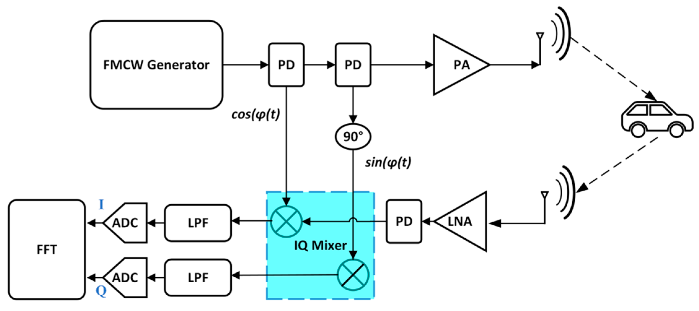
4.1. A Complex Baseband FMCW Radar

Figure 1 depicts a system-level diagram of an FMCW radar employing an in-phase and quadrature (I/Q) complex baseband architecture. One of the most widely utilized waveforms in said radars is linear frequency modulation (LFM). The FMCW generator routes an LFM-modulated continuous wave for amplification at the power amplifier (PA) stage. Following the reflection from the target, the wave undergoes low noise amplification (LNA) at the receiver. Afterward, it is multiplied by a time-delayed and a time-delayed with a 90-degree phase offset version of the transmitted wave in the respective paths. Subsequently, both signals pass through low-pass IF filters to eliminate high-frequency elements. This yields the I and Q components, which are then sampled by analog-to-digital converters (ADCs) and prepared for further signal processing. Power dividers (PDs) are employed at various stages of the process, given the parallel processing inherent in complex baseband architecture. The transmitted signal, S T x , can then be given as
S T x = A T x c o s ( 2 π f ( t ) t + φ T x ( t ) ) ,
where φ T x ( t ) and A T x are the initial phase and the amplitude of the transmitted signal and f t is the instantaneous frequency of the FMCW generator, given by
f t = f c + S t ,
where f c is the initial carrier frequency and S is the slope of the LFM waveform, the rate of change of frequency sweep with respect to time. This signal is also known as chirp. Figure 2 shows an LFM chirp with BW   B , given by the equation
B = S T c .
Similarly, the received signal S R x after reflection from the target, can be expressed as
S R x = A R x c o s ( 2 π f c t + φ R x ( t ) ) ,
where φ R x ( t ) and A R x are the initial phase and the amplitude of the received signal. As the received signal is subject to multiplication with the transmitted signal, a duration τ is elapsed, known as the roundtrip time of flight (RTOF) expressed using Newton’s second law of motion as
τ = 2 R c ,
where R is the range of the target from the radar and c is the speed of light. Using the formula for the product to sum trigonometric functions yields the following signal at the output of the mixer:
S T x . S R x = 1 2 c o s 2 π S τ t + φ T x t φ R x t + 1 2 c o s 2 π S τ t + 4 π f c t + φ T x t + φ R x t .
Afterward, the low-pass filter suppresses the high-frequency component containing 4 π f c t . The difference of frequencies comes out to be f I F and the phase difference φ T x ( t ) φ R x ( t ) , is the initial phase of the resultant I and Q components of the IF signal, expressed as
φ I F = 2 π f c τ .
Plugging (5) into (8) and expressing (7) in terms of wavelength, λ , gives us the following:
φ I F = 4 π R λ .
Equation (6) can then be used to express I I F as
I I F = 1 2 A I F c o s ( 2 π f I F t + φ I F ) ,
where A I F is the amplitude of the signal. Similarly, Q I F can be given as
Q I F = 1 2 A I F s i n 2 π f I F t + φ I F .
Subsequently, the IF signal, S I F can expressed as
S I F = I I F + j Q I F ,
which depicts the IF signal as a sum of I and Q components which is subject to signal processing in the next stage for range, velocity, and angle of arrival estimation.

4.2. Range Estimation

The basic working principle of an FMCW radar is the transmission of a chirp in the radar field of view (FOV) which is reflected off targets in its path and received with a delay depending upon the distance of the target from the radar. This RTOF of the EM wave traveling at the speed of light constitutes the basis for range estimation. The terms target and object have been used interchangeably in this article. Section 4.1 provided general expressions for the I and Q components of IF. A simplified alternative using the equation of the line may be leveraged for modeling the process of IF generation. Since this section aims to present a simplified discourse on the theoretical aspect of performance metrics, the ensuing discussion considers a real baseband architecture.
The received chirp is multiplied with its time-shifted version from the output of the FMCW generator yielding the sum and difference terms. The summed component is suppressed by the low-pass filter, leaving only the difference component, f I F . Figure 3 exhibits this phenomenon with a constant IF signal generated for the duration of the overlap between the transmitted and received chirp. IF signal generation can be explained with the line equations of the transmitted (Tx) and received (Rx) chirps.
For the sake of simplicity, the carrier frequency term f c is neglected, and the starting point of the Tx chirp is assumed at the origin of the cartesian plane. The line equation for the Tx chirp with a y-intercept at the origin and slope S can then be given as
f T x t = S t .
The Rx chirp has an x-intercept, τ , the RTOF. The y-intercept for the Rx chirp using the line equation comes out to be S τ . The line equation for the Rx chirp can then be expressed as
f R x t = S t S τ .
Then, subtracting (13) from (12) yields
f I F = f T x t f R x t = S τ .
It should be noted that f I F is constant for the duration of the overlap between the Tx and Rx chirp. Every object in the radar FOV generates a unique IF termed as the beat frequency. Its value depends on the chirp slope and RTOF. Using (5) and (14), the expression for IF as a function of the target range can be rewritten as
f I F = 2 S R c .

4.3. Maximum Range and Range Resolution

As signified by (15), f I F is directly proportional to the range of the target. Therefore, it can only be increased to a limit beyond which the cut-off frequency of the IF filter becomes a bottleneck. Being a low-pass filter, the cut-off frequency is essentially the IF filter BW. Per the general specifications of an LRR for the cruise-control use case, the IF filters in automotive radars are designed to serve a few hundred meters of range [50]. Rearranging (15) for the maximum range of an FMCW radar gives us the following:
R m a x ( I F m a x , S ) = c I F m a x 2 S .
The rationale of this article is to highlight the hardware limitations in automotive radars and the constrained IF BW is one such limitation alluded to in the introductory part of the text. However, a reduced chirp slope S may compensate for this constraint. It is imperative that we introduce the range resolution at this stage before further discussion on the intertwined relation of the performance metrics. The range resolution is the ability of a radar to distinctly identify two closely spaced objects. According to the properties of the Fourier transform [51], a time-domain signal with a larger duration has a better frequency resolution. FMCW is a continuous wave radar with an observation window equal to the duration of the chirp signal, T c . The expression for frequency resolution can be expressed as
Δ f I F > 1 T c .
where Δ f I F is the minimum allowable difference between beat frequencies corresponding to two closely spaced objects at a minimum possible distance, Δ R , away from each other. Modifying (16) accordingly and plugging into (17) gives us the following:
2 S Δ R c > 1 T c ,
Δ R > c 2 S T c .
Using (3), Expression (19) can be rewritten as
Δ R ( B ) > c 2 B .
(20) is the expression for the range resolution of an FMCW radar as a function of only the chirp BW.

4.4. Link Budget for Radar Altimeter

The maximum range of an FMCW radar is a function of the IF BW, as well as the SNR available at the receiver. Despite a beat frequency being in the range of the IF filter BW, if the SNR is below the requisite threshold, the requisite range is compromised. Careful estimation is, therefore, prudent in this context. It can be conveniently estimated using the radar range equation, which is a manipulation of the Friss transmission formula [5]. The power received at a monostatic radar reflected from a point target is
P r = P t G t G r σ λ 2 ( 4 π ) 3 R 4 ,
where P t is the transmitted power with G t and G r being the gains of the transmit and receive antennae, respectively, σ is the RCS of the point target, and λ is the wavelength. However, the exception for a radar altimeter use case is that the target is the surface of the ground. Therefore, (21) must be extended for a distributed target to accurately approximate the RCS. Backscattering or clutter from the ground surface is an unwanted phenomenon in surveillance radars; however, it is the intended target for altimeters. For a distributed horizontal ground surface, the RCS can be evaluated using
σ = A i l l σ o d A =   σ o A i l l ,
where σ o is the backscattering cross-section per unit area normalized with respect to the area,   A i l l , of the ground patch illuminated by the radar antenna [52]. Here, σ o is also referred to as the normalized radar cross-section (NRCS). The estimation of the NRCS falls in the realm of empirical research and well beyond the bounds of this article. A generic analytical model serves the scope of this work since the objective is an approximate estimation of the NRCS for a given terrain type. Such models do not adequately address the characteristics of land clutter for remote-sensing or surveillance use cases where more specific details of scatterers are required. For a pure look-down radar altimeter scenario of ψ = 90 ° , the mean NRCS can be evaluated using the as a sum of the low grazing angle regime contribution, and the contribution due to specular scattering [53]:
σ 0 d B ¯ = σ 9.3 G ¯ + 10 log 10 0.65 e t a n 2 90 ψ / t a n 2 ß 0 t a n 2 ( ß 0 ) + 10 log 10 f 9.3 + 10 l o g 10 0.1 ψ ,
where σ 9.3 G ¯ is the mean NRCS at frequency 9.3 GHz for ψ     < 10°, tan 2 ß 0 is the rms surface slope, and f is the operating frequency. The term 10 l o g 10 0.1 ψ is added to cater to the effect of increasing ψ beyond 10°. The reference of 9.3 GHz is evident in the mathematical expression since the specific experiments were conducted at this frequency at a very low grazing angle. The extrapolation beyond this grazing angle and operating frequency deems the model generic and, therefore, an approximation only. For an estimation of backscattering for a radar altimeter, such generic models provide sufficient substance for the estimation of performance metrics and parameters. (23) seems daunting from a mathematical perspective but it only signifies an increase in backscattering from the ground surface with increasing frequency owing to lesser absorption. Additionally, larger grazing angles cause more reflection. Interested readers are encouraged to refer to [52,53,54] for a detailed discourse and a more insightful understanding of clutter estimation from ground terrains. For the sake of completeness, it must be highlighted that the landreflectivity function from MATLAB [55] utilizes the same model for clutter estimation at such high grazing angles and short wavelengths. There is some respite after all in the form of a high NRCS to somehow compensate for the high FSPL in the mmWave realm. The second term in the estimation of RCS is A i l l . Figure 4 illustrates a horizontal elliptical area illuminated by the radar antenna on the ground surface. It is governed by the half-power beamwidth (HPBW) of the antenna in both the azimuth (H-plane) and elevation (E-plane), as well as the altitude [56]. The higher the altitude, the longer the axes of the ellipse. A i l l can be expressed using the area of the antenna beam, A b e a m , and angle of incidence, θ i , as
A i l l = A b e a m c o s θ i .
Assuming a non-symmetrical area of the elliptical antenna beamwidth, (24) can be expanded as
A i l l = π θ e 2 θ a 2 R 2 s e c ( θ i ) ,
where θ a and θ e are the HPBW in radians of the antenna in the azimuth and elevation planes, respectively, and R is the altitude of the platform AGL. The grazing angle, ψ = 90° θ i , for a pure look-down radar altimeter is 90°. Accordingly, the effect of sec ( θ i ) can be ignored in (25). The RCS can now be calculated using (22). Before proceeding to the expression for maximum range, it is crucial to estimate the noise power for the subsequent evaluation of the SNR. The expression of the noise power, P n , in watts is given as
P n = k B T B n F ,
where k B is the Boltzmann constant, T is the temperature in Kelvin degrees, B n is the noise BW, and F is the noise figure of the receiver. It is appropriate to offer some disambiguation and insight into the estimation of the noise BW. This term is often mistakenly approximated in the literature and warrants careful consideration. The only important aspect to understand here is the identification of the exact point where the received signal shall be subject to detection in the receive chain. As shown in Figure 1, after the beat frequencies pass through the IF filter, the signals are sampled in two independent I and Q paths. The time-domain signals I and Q are sampled by the analog-to-digital converter (ADC) and subject to fast Fourier transform (FFT).
Subsequently, the noise power becomes split into frequency bins where the BW of each bin is equal to the inverse of the chirp duration, T c [28,58]. Furthermore, it must be noted here that an FMCW radar generates a series of chips for the estimation of velocity. This aspect was not covered in the theoretical discussion on FMCW radars since velocity estimation is not covered in this work. Nevertheless, there is no restriction on orchestrating a chirp frame with multiple chirps to extract benefits in terms of the increased SNR. Figure 5 shows an N chirp frame. The observation time for the estimation of noise can be extended to the entire frame instead of just one chirp. This is termed the integration time or frame time, T f , given as
T f = N T c .
The noise BW in a frequency bin can then be given as
B n = 1 N T c .
Plugging (28) into (26), the modified expression for P n becomes
P n = k B T F N T c .
It is pertinent to understand that the modified expression for the noise power is consistent with the zero-mean Gaussian distribution of its power spectral density (PSD). It implies that the noise tends to average itself out as the observation interval is increased. To evaluate the maximum range, P r m i n is the threshold for the minimum power that can be used by the radar with an acceptable value of the probability of false alarm (PFA). An estimation of the PFA for the minimum value, S N R m i n , is beyond the scope of this work and, therefore, the value specified by the manufacturer serves the purpose [28]. Using (28), P r m i n can be expressed as a sum of P n   and S N R m i n
P r m i n = k B T F N T c + S N R m i n .
Using (22), (25), and (30), the radar range equation can be modified by moving R to the left side of the equation and canceling R 2 from the expression of A i l l . The final expression for the maximum range can then be given as
R m a x ( S N R m i n ) = P t G t G r σ o θ e θ a λ 2 k B T F N T c + S N R m i n 256 π 2 .

4.5. Supplementary Performance Metrics

The performance metrics elaborated in the preceding text directly govern the waveform specifications of an FMCW radar employed for drone altimetry. However, for the sake of completeness, it is imperative to provide a succinct summary of other metrics as well. Section 6 briefly discusses the potential directions for future work which includes an experimental verification in dynamic conditions. Nevertheless, one of the concerns in range estimation is the rapid rate of descent (RoD). Moreover, the vertical velocity component becomes more relevant if RoD estimation is necessitated.
Moreover, with the widespread use of AoA estimation in emerging applications, it is essential to briefly summarize the associated performance metrics as well. Given the scope of the existing work, an abridged discussion on velocity and angular estimation has been offered in the proceeding text. Readers are encouraged to consult references [21,22,28,29,30,31,46] for detailed derivations.
Velocity estimation in an FMCW radar requires at least two chirps and estimates the range corresponding to each chirp. According to Newton’s second law of motion, the measured phase difference corresponds to the motion Δ d of the target given as
  Δ d = v T C .
Plugging Δ d from (32) into (8), the phase difference Δ φ I F   can be expressed as
Δ φ I F = 4 π v T c λ .
Rearranging (33), the final expression for velocity estimation comes out to be
v = λ Δ φ I F 4 π T c .
The phase difference can only be increased to a limit | Δ φ I F | < π beyond which the estimation becomes ambiguous. Accordingly, the upper bound on the maximum unambiguous velocity is given by
v m a x = λ 4 T c .
The two-chirp velocity measurement method fails when multiple objects with different velocities align at the same radar distance, generating identical IF frequencies and resulting in a single peak in the range-FFT. To address this, the radar system transmits a chirp frame of N equally spaced chirps for an accurate velocity measurement as already illustrated in Figure 5. After the range-FFT, another FFT of order N is performed in a second dimension to distribute the phase changes into Doppler bins. According to the properties of FFT,
Δ φ I F > 2 π N .
The final expression for velocity resolution, Δ v , can then be obtained by using (36) and plugging (27) into (31) as
Δ v > λ 2 T f .
Per the application requirements concerning the localization of obstacles and pedestrians in the radar FOV, contemporary automotive radar platforms pack multiple antennae for accurate AoA estimation. The platform under consideration, IWR1843BOOST, offers antenna arrays for AoA estimation in the azimuth, as well as the elevation, planes. Appropriately, AoA is an important performance metric similar to range and velocity. The following discourse covers the basics of this metric considering only two antennae in a single dimension. Practically more than two antennae in multiple dimensions are realized for spatial localization and high AoA accuracy.
The angular estimation relies on the observation that a slight deviation in an object position from the boresight of the radar causes a phase shift in the range-FFT or Doppler-FFT peak. By performing an FFT operation along the antenna dimension, this phase shift can be estimated. Utilizing a minimum of two RX antennae as shown in Figure 6, a phase shift in the FFT peak due to reflected waves arriving at different times facilitates the AoA estimation. Equation (8) is based on the RTOF where the AoA works on the concept of transmission of the EM wave from a single Tx antenna and reception by multiple Rx antennae after reflection from the target. Essentially, the phase difference, therefore, becomes half, since only half the distance is considered in this scenario. Figure 6 shows that the reflected wave arrives at the second Rx antenna after covering a longer distance Δ s . Using fundamental geometry and the assumption that the EM waves are planar since the target lies in the far-field region of the antenna, the distance Δ d can be written as
Δ d = l s i n ( θ ) ,
where θ  is the AoA with reference to the radar boresight and l is the distance between the neighboring Rx antennae. Plugging (38) into (8) with half the RTOF and rearranging, the AoA can then be expressed as
θ = s i n 1 ( λ Δ φ I F 2 π l ) .
As already elaborated in the preceding text, the upper bound for the maximum phase difference for unambiguous measurement is | Δ φ I F | < π . Moreover, (39) elucidates that the maximum AoA estimation, θ m a x = ± 90 ° degrees, is only possible when the antennae are separated by a distance of λ 2 . The derivation of the angular resolution requires a more detailed consideration and extends beyond the scope of this article. From a holistic perspective, its importance cannot be discounted in any radar application. Given AoA evaluation necessitates a third FFT along the antenna dimension, the angular resolution, Δ θ , is expressed in radians as
Δ θ = 2 N  
where N is the number of Rx antennae, as well as the FFT order in the third dimension. In summary, this basic discussion on the AoA serves as a basis for a detailed explanation of TDM-MIMO. Nevertheless, the potential of the velocity and AoA in advancing the capabilities of modern mmWave radar altimeters for UASs requires further investigation to be carried out in future work.

5. Operational Requirements and Radar Specifications

With the preliminary discourse on performance metrics covered, it is appropriate to deliberate on the operational requirements of a radar altimeter intended for UASs. In this context, the existing aviation standards serve as a good reference. In active use for the past half-century, RTCA DO-155, the minimum operational performance standard for low-range radar altimeters, is considered the gold standard [59]. Likewise, EUROCAE ED-30 is a similar standard with minor modifications [60]. Furthermore, the specifications of contemporary radar altimeters developed for the aviation industry serve as a good reference to compare performance metrics [61]. However, these systems generally operate in the 4.2–4.4 GHz band. More recently, radar altimeters employing FMCW in the mmWave band with a high update rate and dynamic range designed specifically for small- to medium-scale drones have emerged [39]. To this end, there is no such reference specifically dedicated to radar altimeters intended for use on UASs. It is therefore not possible to have a one-to-one mapping of every single requirement listed in the referred standards. This article strives to adapt the existing MOPSs for radar altimeters used in commercial aviation for applicability to UASs. The requirements of reliability and the environmental stress screening of avionics for commercial and military aviation is a separate domain that is more related to the product aspect than the technological aspect. With this understanding, the discussion on performance metrics has been kept to the maximum and minimum measurable altitude, the measurement accuracy, and the update rate.

5.1. Minimum Update Rate

The referred standards do not explicitly state the requirements of the update rate and, instead, specify the antenna HPBW as a crucial requirement. To the best of the authors’ understanding, the requirement of a wide HPBW implies that the projection of the antenna on the ground surface shall be large enough such that the platform does not cover a longitudinal distance more than the major axis of the elliptical antenna illumination on the surface of the ground between two successive updates from the radar sensor.
For a symmetric radiation pattern, the choice of antenna orientation is irrelevant. However, UAV platforms displace faster along the longitudinal direction than yaw or roll. Therefore, it is logical to orient the antenna such that the larger HPBW is along the longitudinal motion of the platform. This study considers the specifications of the development platform, IWR1843BOOST, for the evaluation of waveform parameters. For the given board, the azimuthal HPBW is greater than the elevation HPBW [62] and, therefore, used in subsequent mathematical expressions. From (25), the length of the major axis, D , of the ellipse can be mathematically given in terms of the altitude, R, as
    D = θ a 2 R .
To estimate the minimum update rate, for a platform capable of traversing at maximum velocity, V m a x , and a minimum altitude requirement of R m i n , the maximum time between successive updates is upper-bound by
Δ t m a x θ a 2 R m i n V m a x   .
This upper bound signifies that there is a minimum requirement of fetching the successive altitude data before the overlap of elliptical antenna projections on the surface of the ground reaches zero over the time period Δ t m a x . The inverse of this duration, the minimum update rate, U m i n , can then be given as
U m i n = 1 Δ t m a x .
The crux of this discussion is that, as the altitude of the platform decreases, the antenna projection becomes smaller and there is a requirement to rapidly update the altitude information, particularly during the landing stage. Furthermore, faster platforms necessitate a rapid update rate, hence an inverse relationship. Figure 7 illustrates this phenomenon.

5.2. Range Resolution and Accuracy

In the context of radar altimeters, the range resolution essentially translates to range accuracy since a finer range resolution allows for the more precise discrimination between altitude levels. If the range resolution is too coarse, it may lead to ambiguity in determining the actual altitude within a given range bin. The range accuracy requirement can be inferred conveniently from aviation standards [59,60]. The requirement for range accuracy is ±1.5 ft, which equates to a range resolution of 3 ft or 0.9 m. However, there is room for the lower limit of measurable altitude being 20 ft to be improved for the case of small-sized drones relying solely on a radar sensor for landing. Since most legacy radar altimeters operate between 4.2–4.4 GHz, there is a requirement to keep a significant separation between the transmit and receive antennae to avoid signal coupling. The mmWave length has an intrinsic benefit of a very small antenna separation requirement. This, coupled with the high range resolution, enables a significantly smaller minimum measurable altitude value. This feature may be particularly useful during the flight operation of mini-drones to aid in efficient traffic management within the scope of smart cities [63].

5.3. Maximum and Minimum Measurable Altitude

The determination of the minimum altitude is tied to the resolution of the range bin and the application of a high-pass filter to mitigate coupling effects from the Tx chain. This is an inherent challenge as the Tx and Rx chains operate simultaneously in FMCW radars. Owing to a wavelength, λ , of 3.9 mm at the 77 GHz operating frequency, even with an antenna separation of 10 λ , the high-pass filter can be conveniently programmed to filter out the coupling effects.
Although the concept of the range bin is related to the signal-processing domain, it is important to discuss it in the context of the minimum measurable altitude. A range bin is the smallest measurable unit by a radar. It may be interchangeably used with the range resolution as per the discussion in Section 5.2. It is governed by the ADC sampling rate, F s , chirp slope, S , and size of the FFT, N F F T [28,46]. The mathematical expression is as follows:
Δ R ( F s , N F F T , S ) = c F s 2 S N F F T .
Nevertheless, this raises the question about the necessity of having two distinct expressions for the range resolution, (20) and (44). Each equation holds its validity within its context. Achieving the range resolution as defined by Equation (20) requires adjusting the parameters in Equation (44) accordingly. It explicitly signifies that a higher-order FFT is bound to enhance the separation of the frequency components in a time-domain signal, resulting in a finer range resolution. In essence, Equation (20) delineates the range resolution based on the chirp BW of the waveform provided that the signal-processing chain, accordingly, offers the required FFT size. Accordingly, Δ R can be expressed in terms of (20) and (44) as
A l t a c c M a x c F s 2 S N F F T , c 2 B .
The readings, starting from the DC range bin to the mth range bin, with m Δ R corresponding to the Tx and Rx antenna separation, are to be removed from the altitude measurement. This necessitates a lower bound for the minimum measurable altitude. For a separation between the Tx and Rx antenna, Δ x , the value of the range bin indices to be removed can be given as
m = R o u n d u p Δ x Δ R .
where R o u n d u p is rounding off the decimal value to the next nearest integer. The minimum measurable altitude, A l t m i n , can then be given as a lower bound:
A l t m i n m Δ R .
For mmWave frequencies, R m i n is much smaller than the requirements specified in the reference MOPS. However, for small-sized drones flying at low altitudes, the requirement may be stringent. The radiation patterns of an antenna are impervious to the distance from the source only in the far-field region. Therefore, any interference from a nearby radiating source in the near field and Frensel region is likely to cause destructive or constructive inference and affect the far-field radiation pattern [64]. This commands the Tx and Rx antennae to be separated at least by a distance, Δ y , dictated by the following expression
Δ y 2 L 2 λ .
where L is the largest dimension of the antenna and λ  is the wavelength. This separation requirement is significantly higher for the 4.2–4.4 GHz band, owing to the large wavelength. Subsequently, filtering the coupling signature from the Tx antenna requires a high-pass filter with a greater cut-off frequency followed by a higher value of the minimum measurable altitude. Nonetheless, this is another inherent benefit of mmWave FMCW radars coupled with a simultaneous transmit and receive operation—very low altitudes can be reported accurately unlike the Pulse Doppler counterpart. The far-field region of a microstrip patch antenna designed for 77 GHz allows the Tx and Rx antennae to be placed in close proximity, enabling a relaxed lower bound on the altitude measurement.
One important aspect to be apprised here is the role of the complex baseband architecture in absolving F s from the Nyquist sampling criteria [65]. Essentially, the simultaneous sampling of I/Q components indirectly fulfils the Nyquist sampling criteria, but, since both components are being sampled in parallel, the minimum sampling requirement imposed by the Nyquist theorem to sample the incoming signal at twice the I F m a x is reduced by half [66]. There are other benefits of using a complex baseband architecture that warrant an in-depth discussion in the signal-processing domain.
With the number of range bins being N F F T , the expression for the maximum range can be given as
R m a x N F F T , Δ R = N F F T Δ R .
The above expression implies that, for a given N F F T , the maximum range decreases as the range resolution increases. This is an interesting phenomenon that results in the processing ability of the DSP being a critical bottleneck. Similar to the discussion on the range resolution, (16) and (31) assume that (49) does not limit the evaluated maximum range in the respective expressions. Essentially, if the hardware constraints governing the SNR and the I F m a x is not a limitation to achieving a higher value of the maximum range, the processing prowess is still a constraint on simultaneously increasing the range and resolution. The upper bound for the maximum altitude in terms of (16), (31), and (49) can therefore be approximated as
          A l t m a x   Min   R m a x ( N F F T , Δ R ) , R m a x ( S N R m i n ) ,   R m a x ( I F m a x , S ) .

5.4. Waveform and Radar Specifications

Given that the maximum range and resolution are governed by multiple expressions and the evident interdependence, an open-ended evaluation is bound to become a multivariate optimization problem, which does not align with the model of operational requirements. To culminate the discussion on performance metrics and facilitate the readers in the inference of waveform specifications more effectively, it is crucial to examine a realistic UAS scenario and succinctly outline the resultant radar specifications aligned with those requirements. It is only practical to imply that the specifications of the radar altimeter stem from the requirements of the platform and not vice versa. An example test case follows with the operational requirements of a UAS summarized in Table 2 with the hardware specifications of the radar presented in Table 3. The references are cited in the remarks column where applicable.
Table 4 entails the resultant waveform and radar specifications. The remarks column contains the equation numbers for the convenience of readers. The evaluations yield a fair promise with the reference standards and state-of-the-art products [39,59,60,61]. Section 7 provides a discussion on these specifications and potential methods for further improvement. Moreover, the parameters and waveform specifications are provided in a sequential manner starting from the maximum time between successive updates and finishing with the maximum measurable altitude.

6. Future Work and Challenges

The proposed direction of mmWave radar altimeters is a relatively modern concept. Like any other technology, there is a lot of potential for rigorous improvement with the accompanying challenges.

6.1. Future Work

This article is the initial segment of an ongoing mmWave radar altimeter project. This text concentrates on a careful literature review, an exploration of MOPSs, an examination of the state of the art, and the establishment of the theoretical foundation. Next in line is to identify relevant signal-processing techniques for true altitude estimation. In the presence of multiple scatterers in the antenna beamwidth, the most useful altitude estimate is the one obtained directly beneath the nose of the UAS platform. To cater to this requirement, one such direction is the exploration of mmWave TDM-MIMO [32] for the radar altimeter use case. Having a spatial resolution in radar altimeters is a nascent concept that can be extremely useful in true altitude estimation. Moreover, to make the best use of processing resources on automotive radars, it is imperative that we study and evaluate the signal-processing techniques prevalent in ADASs for their applicability in radar altimeters. For instance, the efficacy of the CFAR algorithm for the detection of the ground and the selection of associated design parameters for this particular application is unreported. Similarly, signal-processing algorithms used in industrial applications can be applied to improve range accuracy. Liquid-level sensing radar systems use algorithms like Zoom-FFT [67]. There is plenty of room for exploration and use in the very-high-accuracy landing requirements of UASs or commercial aviation. Zoom-FTT provides a coarse range estimation, followed by magnifying a specific portion of the frequency spectrum for accuracy enhancement beyond the conventional limits of the radar. Accuracies in the mm range have tremendous application avenues specifically as a backup for weight-on-wheel systems in fixed-wing UASs or commercial aircraft. There is a dire need to extend the scope of the work toward experimental verification across varied ground surfaces, including snow, water, grass, and concrete. More importantly, the performance of the radar altimeter against complex textures such as large forest and green vegetation may warrant careful signal-processing algorithms. Moreover, flying birds and waterfalls under the UAS airframe during the flight is another concern to be investigated. The discussion on velocity has not been made a part of this study. However, during the rapid rate of ascent and descent of UASs, the effect of velocity needs to be studied. The experimental work is bound to not only validate the theoretical presentations of this work but also appraise the signal-processing techniques to be explored in the next stage.
There has been a plethora of work carried out in the domain of machine learning/deep learning (ML/DL) using radar sensors for automotive applications. Surveys in [8] and [68,69] show the potential research directions and experimental research conducted. ML/DL are traditionally employed in object detection and classification within ADASs. A survey dedicated to their efficacy in the UAS domain is presented in [70]. Based on the extraordinary work being carried out, it is rational to highlight that these techniques hold promising applications in the field of drone altimetry. Beyond their conventional uses, these technologies can be leveraged for advanced functionalities. One such application involves the prediction of interference from neighboring radars or electromagnetic sources, distinguishing it from authentic radar returns. Another innovative approach is the utilization of machine-learning algorithms to discern ground surface types, dynamically adjusting the chirp and frame configurations in response. A particularly noteworthy concept may involve the autonomous adaptation of radar altimeter modes based on the operational state of the UAV, specifically during the landing approach in autopilot mode. Trained on nuanced patterns in radar altitude data, ML/DL models could be leveraged to integrate variables such as the rate of descent, surface type, and current altitude to intelligently switch to a high-accuracy mode. In this heightened accuracy mode, sacrificing the maximum range for precision aligns with the specific operational requirements of precise landing. Concurrently, it offers a redundant safety measure akin to a backup for weight-on-wheels systems. This strategic integration of ML/DL not only optimizes the radar altimeter performance across diverse flight modes but also underscores its potential to elevate overall flight safety.

6.2. Challenges

Amongst the challenges inherent in integrating a microstrip patch antenna and radar chip on the same printed circuit board PCB at 77 GHz, radome design and fabrication is crucial for deployment on UAS. The purpose of a radome is to protect the antenna and electronics from environmental effects. The design and fabrication of a radome is a potential cost overhead. Moreover, the inclusion of MIMO in the next phase of the work implies that an array of multiple Tx and Rx antennae shall be deployed. While horn antennae may be considered, their installation and calibration on UAS airframes entail substantial cost, effort, and volume implications. The requirement of precise antenna separation deems conformal microstrip patch antennae the optimal choice. Nevertheless, their manufacturing and characterization is a daunting task. There is a need to explore cheap substrates with a small Young’s modulus [71] for bending and rolling to fulfill the said task. Traditional testing methods with a vector network analyzer (VNA) and anechoic chamber are expensive. A cheaper alternative could be to employ the radar unit itself as a test bench by incorporating targets with a known RCS at a calibrated distance to gauge the practical gain against simulated results since the rich software control offered by Texas Instruments allows for real-time SNR evaluation [72]. Nevertheless, the characterization of the radiation pattern for HPBW evaluation is a research venture of its own.
Another challenge is that there is no evidence of the long-term performance and reliability of mmWave automotive radars for airborne applications. Although automotive-grade electronics have a wide operating temperature range and experience significant vibration through the course of the life cycle, the vibration spectrum of a broad scale of UAS platforms may pose additional stress. Moreover, if the scope is extended to commercial aviation, long-term exposure to very low temperatures at high altitudes may warrant accelerated life testing. These are unexplored areas and a thorough investigation is necessary for the mmWave band to become a viable avenue given the 5G interference and inherent benefits associated with this migration.

7. Discussion

The goal of this effort was to establish the applicability of mmWave automotive radars for radar altimeters of UASs. To realize this goal, the article has offered a discussion on the feasibility, benefits, and methodology for exploring the 77 GHz mmWave automotive radars in the wake of 5G interference in the dedicated 4.2–4.4 GHz band. The cost-effectiveness, easy accessibility, and FMCW waveform offered on the MMIC position them as a lucrative candidate. In this work, their suitability with intrinsic hardware limitations was appraised theoretically. With very few reference works for researchers and academicians to benefit from, a tutorial-themed discourse comprising a simplified mathematical expression was furnished. Another important milestone of this work was to present a brief and meaningful discussion on backscattering from the ground surface in a mmWave radar altimeter scenario. The scope of this discussion for 77 GHz automotive radars being evaluated for a radar altimeter use case was previously unreported. This direction is poised to aid youthful researchers and system engineers alike in better understanding the performance metrics.
The authors’ comments throughout the entire course of the text have been aimed at providing the basis for the optimization of available resources. Nevertheless, it is in no way implied that the hardware limitations cannot be improved upon. For instance, R m a x ( I F m a x , S ) was found to be a bottleneck that brought the A l t m a x down. The benefits of migration to the 77 GHz band remain equally applicable if the problem of the mmWave radar altimeter design is approached with a modular radar that offers the flexibility to increase I F m a x . Despite a complex baseband architecture, this direction demands a higher F s . Subsequently, a proportionate increase in N F F T is poised to keep Δ R ( F s , N F F T , S ) relatively constant while offering an increase in R m a x ( I F m a x , S ) proportional to I F m a x . However, it must be noted that having a higher N F F T requires more processing resources, which is possible with a dedicated, more powerful processor. It was underscored in Section 3 that EM waves traversing at 77 GHz are expected to experience a high FSPL followed by a compromised SNR at the receiver. Contrariwise, it was observed that a higher NRCS for smaller wavelengths compensates for the high FSPL. This, along with a wide HPBW in both planes and a longer observation window, enables a promising R m a x ( S N R m i n ) . In summary, impartial to the choice of hardware, the discussions and findings of this article are composed to propel the narrative towards the mmWave altimeter. Nevertheless, a modular approach is certain to add volume and cost overhead.
The lack of dedicated MOPSs for radar altimeters of UASs required some deliberation for repurposing commercial application standards for the required use case. The authors’ notes are backed by the theoretical and mathematical rationale to rationalize the operational requirements accordingly. The discussion on the performance metrics and their interconnected nature required a careful approach in order to exploit the performance to its fullest. The authors exercised great care in presenting a systems engineering approach. To culminate the work, an example test case was presented with operational requirements followed by the derived radar specifications.
It is appropriate to point out that this body of work is the first in a series of an ongoing project concerning mmWave radar altimeters. The scope of future work is stated in Section 6. For the sake of completeness, it is stated that the sequential approach towards the eventual goal shall encompass a dedicated text on signal processing. A completely novel direction is the exploitation of ML/DL methods to classify the flight modes in UAV operation for subsequent waveform optimization. Lastly, experimental work with real-time aerial testing onboard the UAS platform is poised to culminate the theoretical basis and discussions with practical validation in the field.

8. Conclusions

In the wake of 5G interference with legacy radar altimeters, the article deliberates on the feasibility of employing mmWave FMCW automotive radars for UAS altimetry. A brief history of contemporary systems and the rationale for device selection is briefly touched upon in the context of frequency regulations, opportunities, and drawbacks. Theoretical and mathematical basis, coupled with tutorial-themed discussions, for understanding the intertwined performance metrics are furnished to address a broad range of readers. A ground clutter estimation using the hardware specifications of a mmWave automotive radar for a pure look-down case is provided. Owing to the dearth of MOPSs for UAS radar altimeters, the existing standards for commercial aviation are appraised for the requisite adaptation. A systems engineering methodology for deriving waveform and radar specifications from operational requirements is offered. Subsequently, the authors’ perspective on the optimization of performance metrics and potential improvements through alternative methods was penned down. It is argued that the scope of this work is poised to propel the discussion towards mmWave altimeters. Lastly, the scale of future work and associated challenges in realizing the full potential of the proposed approach are put forth.

Author Contributions

Investigation, resources, visualization, and writing—original draft preparation, M.A.A.; conceptualization, M.A.A., Y.D. and A.K.; validation, supervision, and writing—review and editing, Y.D., M.D. and A.K. All authors have read and agreed to the published version of the manuscript.

Funding

This research received no external funding.

Data Availability Statement

No new data were created or analyzed in this study. Data sharing is not applicable to this article.

Conflicts of Interest

The authors declare no conflicts of interest.

References

  1. Zhang, X.; He, Z.; Ma, Z.; Jun, P.; Yang, K. VIAE-Net: An End-to-End Altitude Estimation through Monocular Vision and Inertial Feature Fusion Neural Networks for UAV Autonomous Landing. Sensors 2021, 21, 6302. [Google Scholar] [CrossRef]
  2. Gebre-Egziabher, D.; Hayward, R.C.; Powell, J.D. A Low-Cost GPS/Inertial Attitude Heading Reference System (AHRS) for General Aviation Applications. In Proceedings of the IEEE 1998 Position Location and Navigation Symposium (Cat. No.98CH36153), Palm Springs, CA, USA, 20–23 April 1998; IEEE: Piscataway, NJ, USA, 1998; pp. 518–525. [Google Scholar] [CrossRef]
  3. Royo, S.; Ballesta-Garcia, M. An Overview of Lidar Imaging Systems for Autonomous Vehicles. Appl. Sci. 2019, 9, 4093. [Google Scholar] [CrossRef]
  4. Pulutan, D.K.A.; Marciano, J.S. Design Trade-Offs in a Combined FMCW and Pulse Doppler Radar Front-End. In Proceedings of the IEEE 2013 Tencon—Spring, Sydney, NSW, Australia, 17–19 April 2013; IEEE: Piscataway, NJ, USA, 2013; pp. 567–571. [Google Scholar] [CrossRef]
  5. Richards, M.A.; Scheer, J.A.; Holm, W.A. (Eds.) Principles of Modern Radar: Basic Principles; Institution of Engineering and Technology: London, UK, 2010; ISBN 9781891121524. [Google Scholar] [CrossRef]
  6. Fujibayashi, T.; Takeda, Y.; Wang, W.; Yeh, Y.-S.; Stapelbroek, W.; Takeuchi, S.; Floyd, B. A 76- to 81-GHz Multi-Channel Radar Transceiver. IEEE J. Solid-State Circuits 2017, 52, 2226–2241. [Google Scholar] [CrossRef]
  7. Srinivasan, V. CMOS MMIC Ready for Road, A Technology Overview. February 2018. Available online: https://www.ti.com/lit/an/swra592/swra592.pdf (accessed on 1 February 2024).
  8. Soumya, A.; Krishna Mohan, C.; Cenkeramaddi, L.R. Recent Advances in mmWave-Radar-Based Sensing, Its Applications, and Machine Learning Techniques: A Review. Sensors 2023, 23, 8901. [Google Scholar] [CrossRef]
  9. Pichavant, C. Use of 4200–4400 MHz Radio Altimeter Band. In Proceedings of the 24th Meeting of Working Group F Aeronautical Communications Panel, Paris, France, 17–21 March 2011. [Google Scholar]
  10. Taylor Canada, J. Handbook on Radio Frequency Spectrum Requirements for Civil Aviation Part I. In Proceedings of the 28th Meeting of Working Group F Aeronautical Communications Panel, Lima, Peru, 11–22 March 2013. [Google Scholar]
  11. Jose, E.; Adams, M.; Mullane, J.S.; Patrikalakis, N.M. Predicting millimeter wave radar spectra for autonomous navigation. IEEE Sens. J. 2010, 10, 960–971. [Google Scholar] [CrossRef]
  12. Ginsburg, B.; Ramasubramanian, K.; Singh, J. Fluid-Level Sensing Using 77-GHz Millimeter Wave; Texas Instruments: Dallas, TX, USA, 2017; Available online: https://www.ti.com/lit/wp/spyy004/spyy004.pdfa (accessed on 6 March 2024).
  13. Weiß, J.; Santra, A. One-Shot Learning for Robust Material Classification Using Millimeter-Wave Radar System. IEEE Sens. Lett. 2018, 2, 1–4. [Google Scholar] [CrossRef]
  14. Omer, A.E.; Shaker, G.; Safavi-Naeini, S.; Murray, K.; Hughson, R. Glucose levels detection using mm-wave radar. IEEE Sens. Lett. 2018, 2, 1–4. [Google Scholar] [CrossRef]
  15. Garcia, K.; Yan, M.; Purkovic, A. Robust Traffic and Intersection Monitoring Using Millimeter Wave Sensors; Texas Instruments: Dallas, TX, USA, 2018; Available online: https://www.ti.com/lit/pdf/spyy002 (accessed on 5 March 2024).
  16. Ahmed, B.; Kara, A.; Zencir, E.; Benzaghta, M. Opportunities and Challenges in Measurement of 9-mm Bullet Model with 77 GHz Mmwave COTS Radar Systems. Microw. Opt. Technol. Lett. 2020, 62, 3772–3778. [Google Scholar] [CrossRef]
  17. Morris, P.J.B.; Hari, K. Detection and localization of unmanned aircraft systems using millimeter-wave automotive radar sensors. IEEE Sens. Lett. 2021, 5, 1–4. [Google Scholar] [CrossRef]
  18. Hu, Y.; Toda, T. Remote Vital Signs Measurement of Indoor Walking Persons Using mm-Wave FMCW Radar. IEEE Access 2022, 10, 78219–78230. [Google Scholar] [CrossRef]
  19. Ran, Y.; Zhang, D.; Chen, J.; Hu, Y.; Chen, Y. Contactless Blood Pressure Monitoring with mmWave Radar. In Proceedings of the GLOBECOM 2022—2022 IEEE Global Communications Conference, Rio de Janeiro, Brazil, 4–8 December 2022; pp. 541–546. [Google Scholar]
  20. Li, W.; Chen, R.; Wu, Y.; Zhou, H. Indoor Positioning System Using a Single-Chip Millimeter Wave Radar. IEEE Sens. J. 2023, 23, 5232–5242. [Google Scholar] [CrossRef]
  21. Skolnik, M.I. Radar Handbook, 3rd ed.; McGraw-Hill Education: New York, NY, USA, 2008. [Google Scholar]
  22. Mahafza, B.R. Radar Systems Analysis and Design Using MATLAB, 3rd ed.; CRC Press: Boca Raton, FL, USA, 2013. [Google Scholar]
  23. Ding, J.; Wang, Z.; Ma, W.; Wu, X.; Wang, M. TDM-MIMO Automotive Radar Point-Cloud Detection Based on the 2-D Hybrid Sparse Antenna Array. IEEE Trans. Geosci. Remote Sens. 2022, 60, 1–15. [Google Scholar] [CrossRef]
  24. Bilik, I.; Longman, O.; Villeval, S.; Tabrikian, J. The Rise of Radar for Autonomous Vehicles: Signal Processing Solutions and Future Research Directions. IEEE Signal Process. Mag. 2019, 36, 20–31. [Google Scholar] [CrossRef]
  25. Patole, S.M.; Torlak, M.; Wang, D.; Ali, M. Automotive Radars: A Review of Signal Processing Techniques. IEEE Signal Process. Mag. 2017, 34, 22–35. [Google Scholar] [CrossRef]
  26. Hakobyan, G.; Yang, B. High-Performance Automotive Radar: A Review of Signal Processing Algorithms and Modulation Schemes. IEEE Signal Process. Mag. 2019, 36, 32–44. [Google Scholar] [CrossRef]
  27. Rao, S. MIMO Radar; Texas Instruments: Dallas, TX, USA, 2018; Available online: https://www.ti.com/lit/an/swra554a/swra554a.pdf (accessed on 3 February 2024).
  28. Rao, S. Introduction to mmwave Sensing: FMCW Radars; Texas Instruments: Dallas, TX, USA, 2017; Available online: https://www.ti.com/content/dam/videos/external-videos/2/3816841626001/5415528961001.mp4/subassets/mmwaveSensing-FMCW-offlineviewing_0.pdf (accessed on 26 January 2024).
  29. Dham, V. Programming Chirp Parameters in TI Radar Devices; Texas Instruments: Dallas, TX, USA, 2020; Available online: https://www.ti.com/lit/an/swra553a/swra553a.pdf (accessed on 4 February 2024).
  30. Ahmed, B. Exploring the Potentials of Commercial Radar Chipsets for Proximity Sensing with Resolving Velocity Ambiguity. Ph.D. Thesis, Atilim University, Ankara, Turkey, 2022. [Google Scholar]
  31. Alizadeh, M. Remote Vital Signs Monitoring Using a mm-Wave FMCW Radar. Master’s Thesis, University of Waterloo, Waterloo, ON, Canada, 2019. [Google Scholar]
  32. Li, X.; Wang, X.; Yang, Q.; Fu, S. Signal Processing for TDM MIMO FMCW Millimeter-Wave Radar Sensors. IEEE Access 2021, 9, 167959–167971. [Google Scholar] [CrossRef]
  33. Wessendorp, N.; Dinaux, R.; Dupeyroux, J.; de Croon, G.C.H.E. Obstacle Avoidance Onboard MAVs Using an FMCW Radar. In Proceedings of the 2021 IEEE/RSJ International Conference on Intelligent Robots and Systems (IROS), Prague, Czech Republic, 27 September–1 October 2021; IEEE: Piscataway, NJ, USA, 2021; pp. 117–122. [Google Scholar]
  34. Sie, E.; Liu, Z.; Vasisht, D. BatMobility: Towards Flying without Seeing for Autonomous Drones. In Proceedings of the 29th Annual International Conference on Mobile Computing and Networking, Madrid, Spain, 2–6 October 2023; ACM: New York, NY, USA, 2023; pp. 1–16. [Google Scholar]
  35. Safa, A.; Verbelen, T.; Catal, O.; Van de Maele, T.; Hartmann, M.; Dhoedt, B.; Bourdoux, A. FMCW Radar Sensing for Indoor Drones Using Learned Representations. arXiv 2023, arXiv:2301.02451. [Google Scholar]
  36. Hugler, P.; Geiger, M.; Waldschmidt, C. 77 GHz Radar-Based Altimeter for Unmanned Aerial Vehicles. In Proceedings of the 2018 IEEE Radio and Wireless Symposium (RWS), Anaheim, CA, USA, 15–18 January 2018; IEEE: Piscataway, NJ, USA, 2018; pp. 129–132. [Google Scholar]
  37. Hugler, P.; Roos, F.; Schartel, M.; Geiger, M.; Waldschmidt, C. Radar Taking Off: New Capabilities for UAVs. IEEE Microw. Mag. 2018, 19, 43–53. [Google Scholar] [CrossRef]
  38. Başpınar, Ö.O.; Omuz, B.; Öncü, A. Detection of the Altitude and On-the-Ground Objects Using 77-GHz FMCW Radar Onboard Small Drones. Drones 2023, 7, 86. [Google Scholar] [CrossRef]
  39. LR-D1 Pro: Dual-Band Radar Altimeter. Available online: https://ainstein.ai/lr-d1-pro-dual-band-radar-altimeter/ (accessed on 7 February 2024).
  40. Hasch, J.; Topak, E.; Schnabel, R.; Zwick, T.; Weigel, R.; Waldschmidt, C. Millimeter-Wave Technology for Automotive Radar Sensors in the 77 GHz Frequency Band. IEEE Trans. Microw. Theory Tech. 2012, 60, 845–860. [Google Scholar] [CrossRef]
  41. Scholvin, J.; Greenberg, D.R.; del Alamo, J.A. Fundamental Power, and Frequency Limits of Deeply Scaled CMOS for RF Power Applications. In Proceedings of the International Electron Devices Meeting, San Francisco, CA, USA, 11–13 December 2006. [Google Scholar]
  42. Pichavant, C. Key Potential Operational Effects from 5G on Radio Altimeter. In Regional Preparations for WRC 23 ATU. Available online: http://tinyurl.com/4awfamc2 (accessed on 2 February 2024).
  43. FCC 47 CFR 15.249 Operation within the bands 902–928 MHz, 2400–2483.5 MHz, 5725–5875 MHz, and 24.0–24.25 GHz. Available online: https://www.govinfo.gov/content/pkg/CFR-2009-title47-vol1/pdf/CFR-2009-title47-vol1-sec15-249.pdf (accessed on 3 February 2024).
  44. Ramasubramanian, K.; Ramaiah, K.; Aginskiy, A. Moving from Legacy 24 GHz to State-of-the-Art 77 GHz Radar, Oct 2017. Available online: https://www.ti.com/lit/wp/spry312/spry312.pdf (accessed on 1 February 2024).
  45. Proakis, J. Digital Communications; McGraw-Hill: New York, NY, USA, 2001. [Google Scholar]
  46. Jankiraman, M. FMCW Radar Design; Artech House: Norwood, MA, USA, 2018. [Google Scholar]
  47. Menzel, W.; Moebius, A. Antenna Concepts for Millimeter-Wave Automotive Radar Sensors. Proc. IEEE 2012, 100, 2372–2379. [Google Scholar] [CrossRef]
  48. Händel, C.; Konttaniemi, H.; Autioniemi, M. State-of-the-Art Review on Automotive Radars and Passive Radar Reflectors, Arctic Challenge Research Project; Research Reports and Compilations; Lapland University of Applied Sciences: Rovaniemi, Finland, 2018. [Google Scholar]
  49. Texas Instruments. IWR1843, Single-Chip 76-GHz to 81-GHz Industrial Radar Sensor Integrating DSP, MCU and Radar Accelerator. Available online: https://www.ti.com/product/IWR1843 (accessed on 31 January 2024).
  50. Park, J.; Ryu, H.; Ha, K.-W.; Kim, J.-G.; Baek, D. 76–81-GHz CMOS Transmitter with a Phase-Locked-Loop-Based Multichirp Modulator for Automotive Radar. IEEE Trans. Microw. Theory Tech. 2015, 63, 1399–1408. [Google Scholar] [CrossRef]
  51. Oppenheim, A.V.; Willsky, A.S.; Nawab, S.H. Signals & Systems; Prentice-Hall: Upper Saddle River, NJ, USA, 1997. [Google Scholar]
  52. Ulaby, F.; Dobson, M.C.; Álvarez-Pérez, J.L. Handbook of Radar Scattering Statistics for Terrain; Artech House: Norwood, MA, USA, 2019. [Google Scholar]
  53. Reilly, J.P.; McDonald, R.L.; Dockery, G.D. RF-Environment Models for the ADSAM Program; Report No. A1A97U 070; Johns Hopkins University Applied Physics Laboratory: Laurel, MD, USA, 1997; Available online: https://apps.dtic.mil/sti/tr/pdf/ADA346190.pdf (accessed on 3 February 2024).
  54. Long, M.W. Radar Reflectivity of Land and Sea, 3rd ed.; Artech House: Norwood, MA, USA, 2001. [Google Scholar]
  55. MathWorks. Reflectivity of Land Surface. Available online: https://www.mathworks.com/help/radar/ref/landreflectivity.html (accessed on 27 January 2024).
  56. Abbas, A.; Elsaid, M.; Mahmoud, S.F.; Abdallah, E.A.; El-Hennawy, H.M. Link Budget Analysis for FMCW Radio Altimeter. In Proceedings of the 2021 International Telecommunications Conference (ITC-Egypt), Alexandria, Egypt, 13–15 July 2021; IEEE: Piscataway, NJ, USA, 2021; pp. 1–4. [Google Scholar]
  57. MathWorks. FMCW Radar Altimeter Simulation. Available online: https://www.mathworks.com/help/radar/ug/fmcw-radar-altimeter-simulation.html (accessed on 28 January 2024).
  58. Blake, L.V. A Guide to Basic Pulse-Radar Maximum-Range Calculation Part 1—Equations, Definitions, and Aids to Calculation; Naval Research Laboratory, Radar Geophysics Branch, Radar Division: Washington, DC, USA, 1969; Available online: https://apps.dtic.mil/sti/pdfs/AD0701321.pdf (accessed on 8 February 2024).
  59. RTCA. Minimum Performance Standard for Airborne Low-Range Radar Altimeters; DO-155; RTCA: Washington, DC, USA, 1974. [Google Scholar]
  60. EUROCAE. Minimum Performance Specification for Airborne Low Range Radio Altimeter Equipment; ED-30; EUROCAE: Saint-Denis, France, 1980. [Google Scholar]
  61. Honeywell. ALA-52B Radio Altimeter. Available online: https://aerospace.honeywell.com/us/en/products-and-services/product/hardware-and-systems/navigation-and-radios/ala-52b-radar-altimeter (accessed on 22 January 2024).
  62. Texas Instruments. IWR1843BOOST Evaluation Module for Single Chip 77GHz mmWave Sensor. Available online: https://www.ti.com/tool/IWR1843BOOST (accessed on 30 January 2024).
  63. Nguyen, D.D.; Rohacs, J.; Rohacs, D. Autonomous Flight Trajectory Control System for Drones in Smart City Traffic Management. ISPRS Int. J. Geo-Inf. 2021, 10, 338. [Google Scholar] [CrossRef]
  64. Balanis, C.A. Antenna Theory: Analysis and Design, 4th ed.; John Wiley & Sons, Inc.: Hoboken, NJ, USA, 2015. [Google Scholar]
  65. Shannon, C.E. Communication in the Presence of Noise. Proc. IRE 1949, 37, 10–21. [Google Scholar] [CrossRef]
  66. Ramasubramanian, K. Using Complex-Baseband Architecture in FMCW Radar Systems. Available online: https://www.ti.com/lit/pdf/spyy007 (accessed on 23 January 2024).
  67. Al-Qudsi, B.; Joram, N.; Strobel, A.; Ellinger, F. Zoom FFT for Precise Spectrum Calculation in FMCW Radar Using FPGA. In Proceedings of the 2013 9th Conference on Ph.D. Research in Microelectronics and Electronics (PRIME), Villach, Austria, 24–27 June 2013; IEEE: Piscataway, NJ, USA, 2013; pp. 337–340. [Google Scholar]
  68. Venon, A.; Dupuis, Y.; Vasseur, P.; Merriaux, P. Millimeter Wave FMCW RADARs for Perception, Recognition and Localization in Automotive Applications: A Survey. IEEE Trans. Intell. Veh. 2022, 7, 533–555. [Google Scholar] [CrossRef]
  69. Abdu, F.J.; Zhang, Y.; Fu, M.; Li, Y.; Deng, Z. Application of Deep Learning on Millimeter-Wave Radar Signals: A Review. Sensors 2021, 21, 1951. [Google Scholar] [CrossRef]
  70. Wilson, A.N.; Kumar, A.; Jha, A.; Cenkeramaddi, L.R. Embedded Sensors, Communication Technologies, Computing Platforms and Machine Learning for UAVs: A Review. IEEE Sens. J. 2022, 22, 1807–1826. [Google Scholar] [CrossRef]
  71. Coonrod, J. Reliably Bend and Form Microwave PCBs. Microw. J. 2013, 56, 92–95. [Google Scholar]
  72. Texas Instruments. mmWave Demo Visualizer. Available online: https://dev.ti.com/gallery/view/mmwave/mmWave_Demo_Visualizer/ver/4.4.0/ (accessed on 8 February 2024).
Figure 1. System-level diagram of an FMCW radar [31].
Drones 08 00094 g001
Figure 2. (a) Slope of f t , and (b) FMCW chirp in time domain [28].
Drones 08 00094 g002
Figure 3. IF signal generation [28].
Drones 08 00094 g003
Figure 4. Area illuminated by radar antenna [57].
Drones 08 00094 g004
Figure 5. FMCW chirp frame [28].
Drones 08 00094 g005
Figure 6. (a) Concept of AoA estimation and (b) maximum angular FOV [28].
Drones 08 00094 g006
Figure 7. Rationale for update rate requirement.
Drones 08 00094 g007
Table 1. Emerging applications of mmWave radars.
ReferenceYearApplication
[11]2010Autonomous robot navigation
[12]2017Fluid level sensing
[13]2018Material classification
[14]2018Blood glucose level detection
[15]2018Traffic monitoring
[16]2020RCS analysis of 9 mm bullet
[17]2021UAS detection and localization
[18]2022Vital sign measuring
[19]2022Blood pressure monitoring
[20]2023Indoor positioning system
Table 2. Operational requirements for radar altimeter of UAS.
RequirementValueRemarks
S N R m i n 20 dB[28]
Accuracy±0.45 m[59,61]
R min 1 mMinimum altitude requirement
R m a x 500 mMaximum altitude requirement
V m a x 20 m/sMaximum platform velocity
T 273.15 °KAntenna temperature
Table 3. Hardware Specifications of Radar.
RequirementValueRemarks
θ a 56°HPBW azimuth [62]
θ e 28°HPBW elevation [62]
P t ( d B m ) 12.5 dBmMAX Tx power, IWR1843 [62]
G t 10.5 dBiIWR1843Boost [62]
G r 10.5 dBiIWR1843Boost [62]
f 77 GHzOperating frequency [62]
λ 3.9 mmWavelength
tan ß 0 0.14RMS surface slope
F 15 dBReceiver noise figure
Table 4. Waveform and altimeter specifications.
ParameterValueRemarks
Δ t m a x 26 msMax time b/w data updates (42)
U m i n 38 HzMinimum update rate (43)
T c 1 msChirp duration
S 1.91 MHz/μsChirp slope
B 1.91 GHzChirp BW (3)
Δ R ( B ) 0.07 mFunction of chirp BW (20)
Δ R ( F s , N F F T , S ) 0.85 mFunction of sampling, FFT and slope (44)
N F F T 1024FFT size
A l t m i n 0.85 mMinimum measurable altitude (47)
A l t a c c 0.85 mAltitude accuracy (25)
N 16Number of chirps/frame
T F 16 msFrame duration (27)
B n 62.5 HzNoise BW (28)
P n −141.27 dBmNoise power (29)
σ 0 2.47Normalized RCS (23)
R m a x ( S N R m i n ) 4548.9 mFunction of minimum SNR (31)
R m a x ( I F m a x , S ) 783.3 mFunction of IF, BW, and Slope (16)
R m a x ( N F F T , Δ R ) 870.4 mFunction of FFT and resolution (49)
A l t m a x 783.3 mMaximum measurable altitude (50)
Disclaimer/Publisher’s Note: The statements, opinions and data contained in all publications are solely those of the individual author(s) and contributor(s) and not of MDPI and/or the editor(s). MDPI and/or the editor(s) disclaim responsibility for any injury to people or property resulting from any ideas, methods, instructions or products referred to in the content.

