

Design, Modeling, and Control of a Composite Tilt-Rotor Unmanned Aerial Vehicle
Abstract
:1. Introduction
- (1)
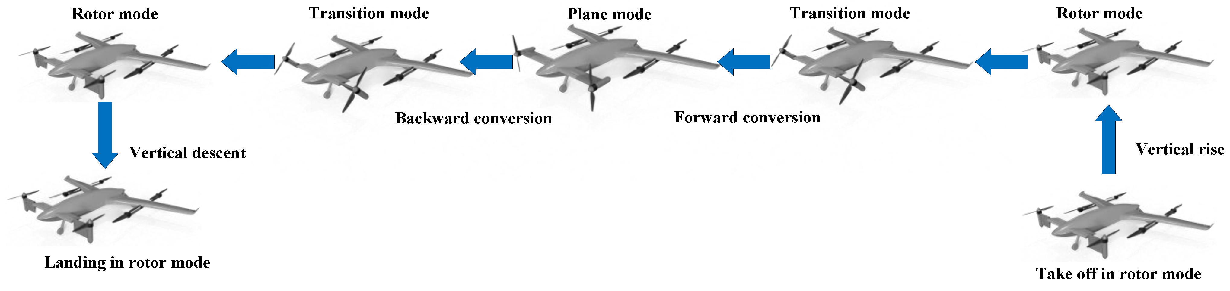
- Propose a distributed composite tilting aircraft that can stably and reliably perform the transition between hovering mode and horizontal flight, and adopt two power systems to better adapt to different flight conditions without using variable pitch propellers.
- (2)
- Aerodynamic modeling uses a combination of numerical simulation and empirical simulation and uses the idea of component modeling to split the aerodynamic analysis of the entire machine into fixed components and tilting components, achieving low-cost and efficient modeling and simulation.
- (3)
- A fused ADRC control architecture suitable for the target aircraft is proposed. The controller has certain anti-disturbance characteristics and can stabilize the aircraft under certain external disturbances and achieve smooth transition and flight in different modes.
2. System Overview
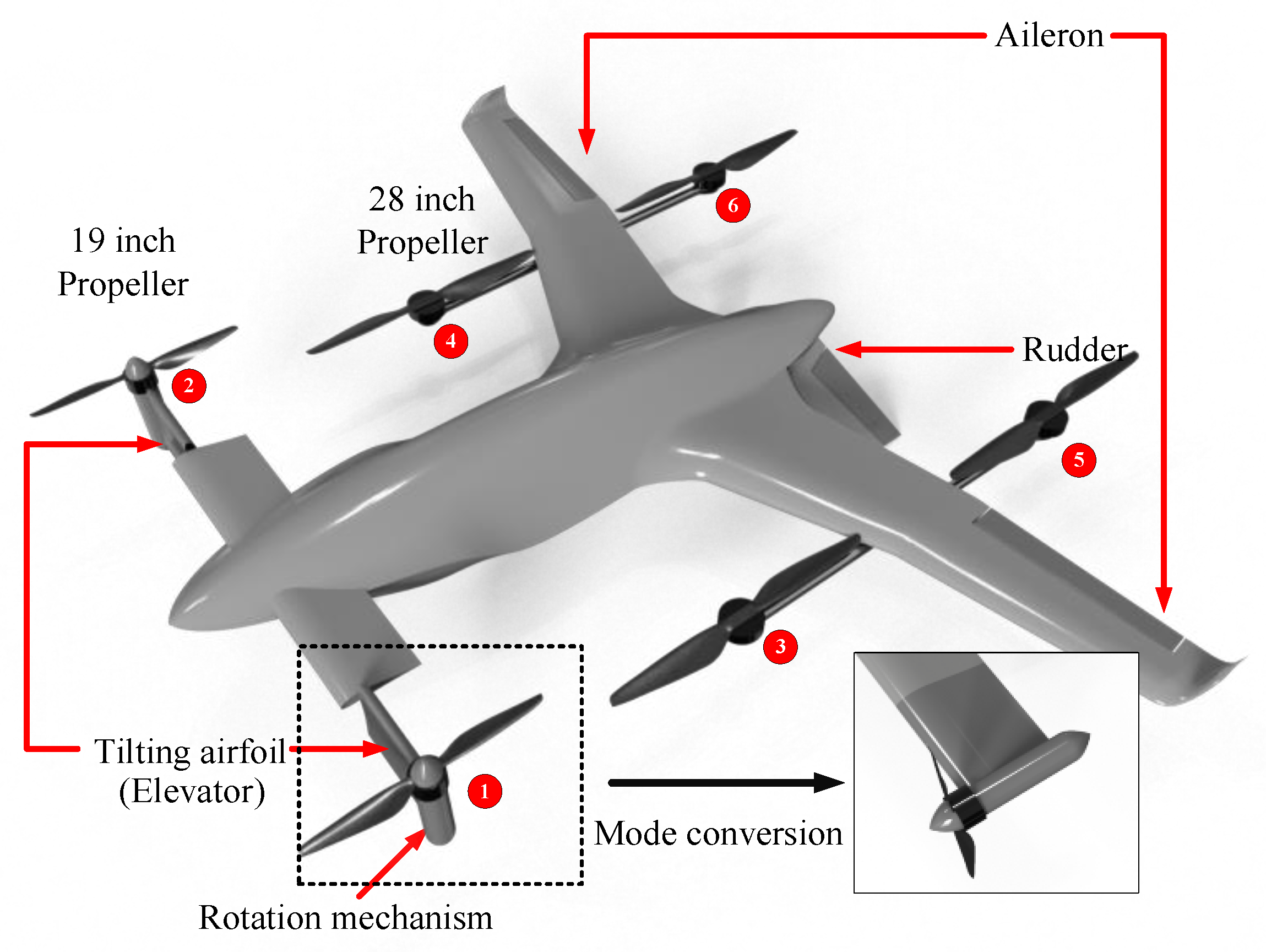
2.1. Aircraft Design
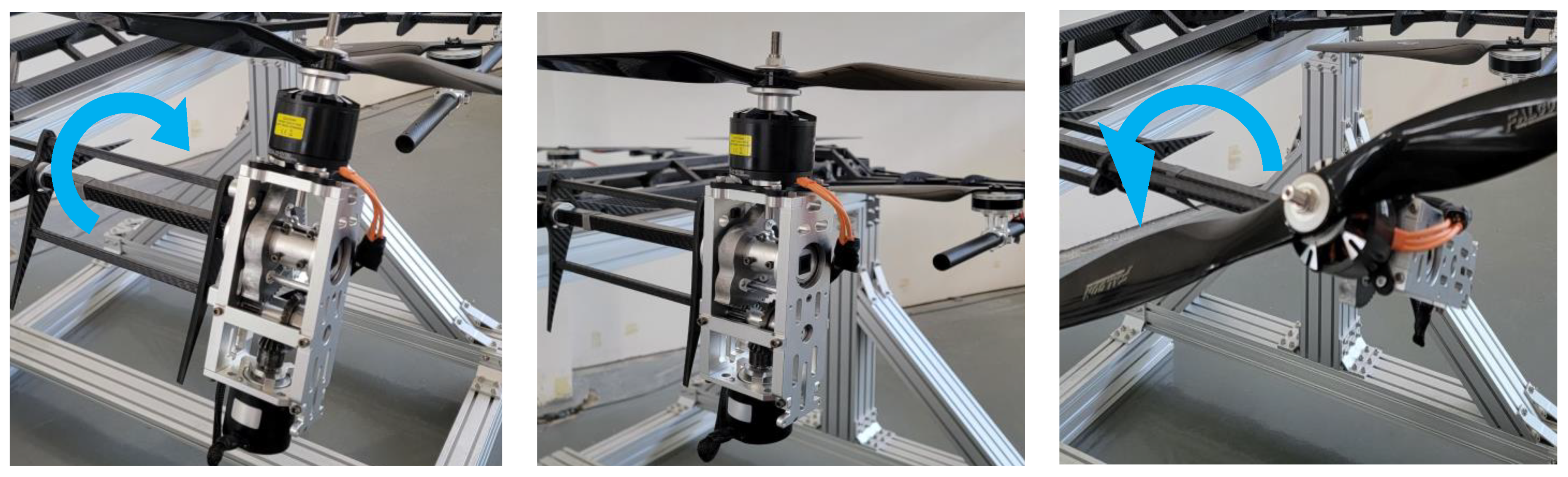
2.2. Tilting Mechanism Design
3. Dynamic Modeling
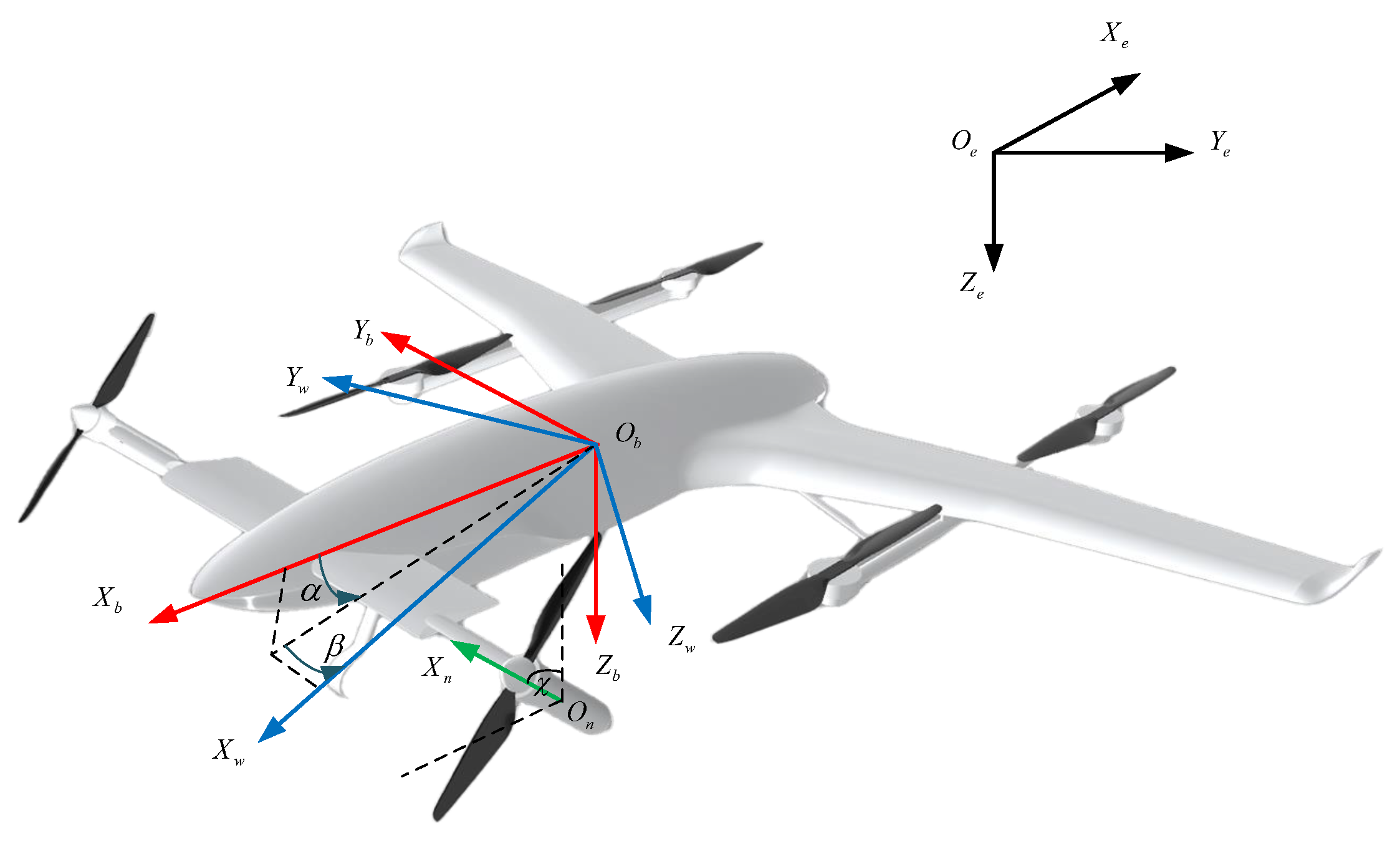
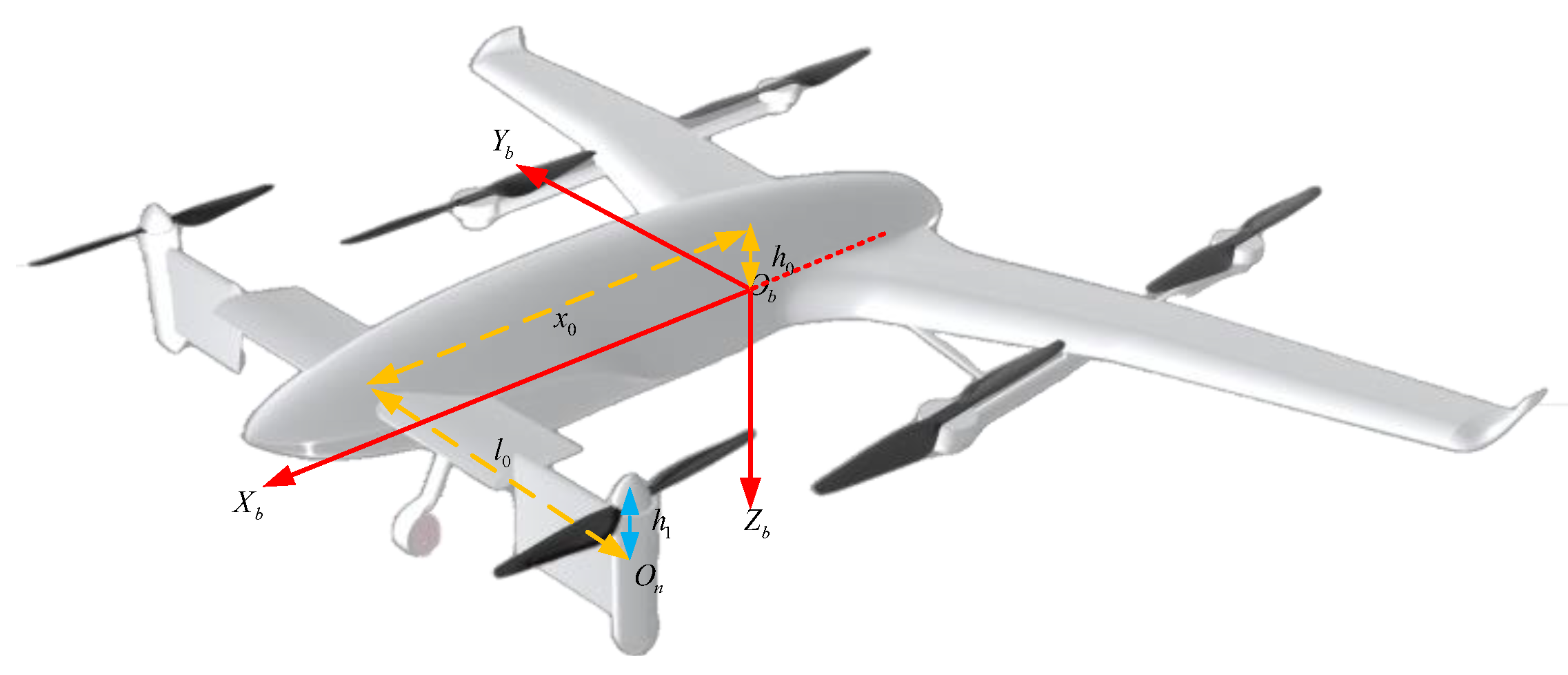
3.1. Definition
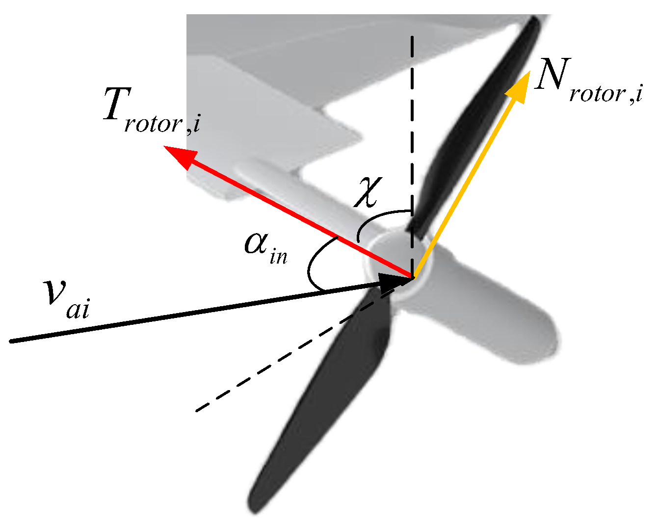
3.2. Modeling of Propeller Force and Torque
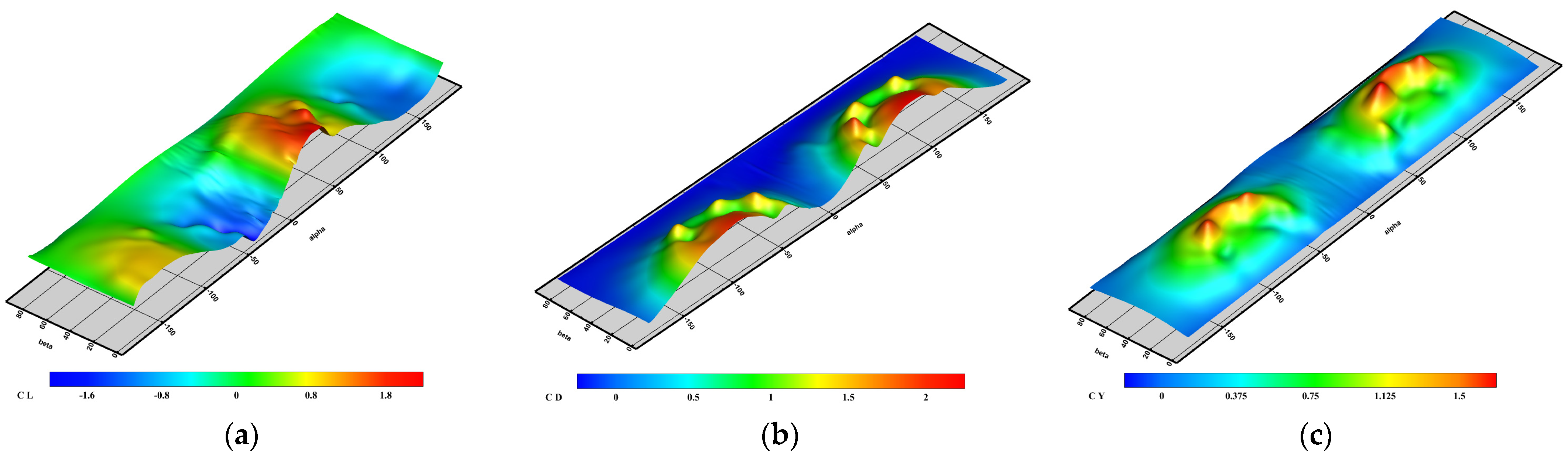
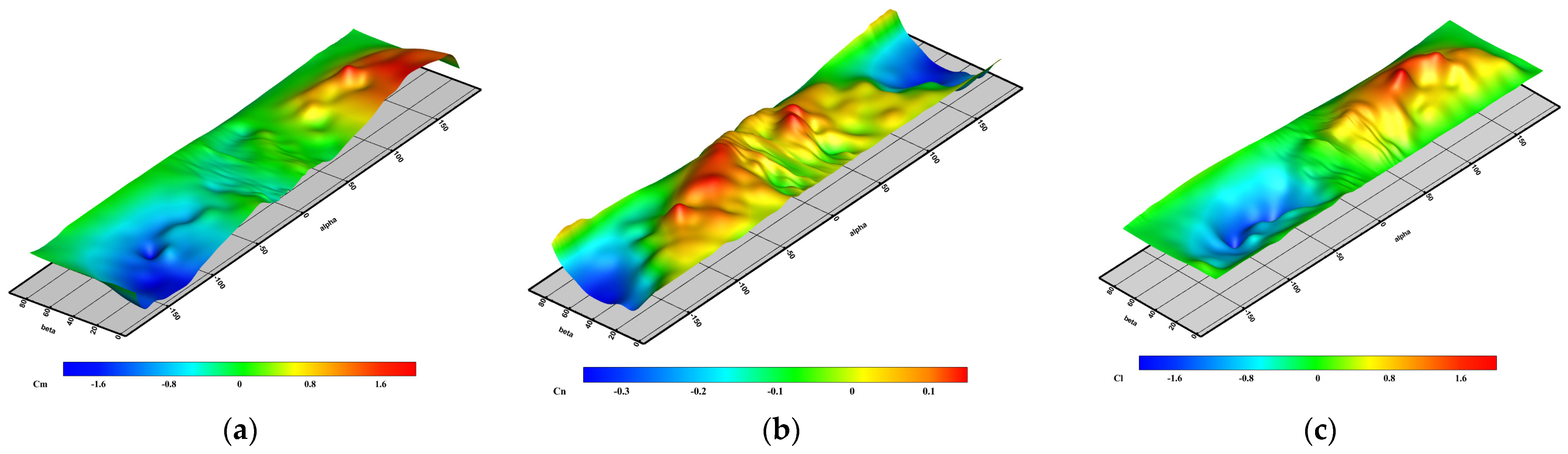
3.3. Aerodynamic Modeling and Simulation
3.3.1. Modeling of Fixed Parts
3.3.2. Modeling of Tilting Section Canard
3.4. Total Force and Moment Modeling
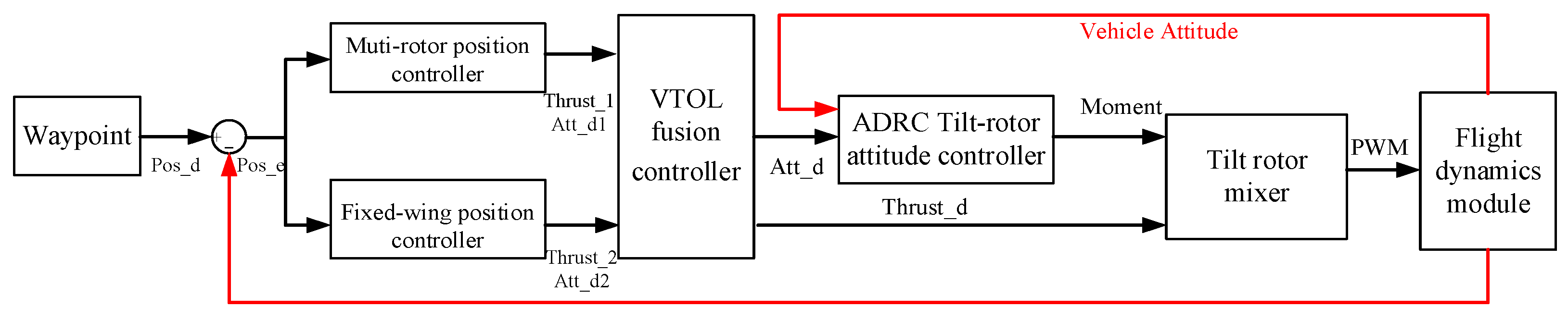
4. Flight Control System Design

4.1. Position Controller
4.2. Vertical Takeoff and Landing Fusion Controller
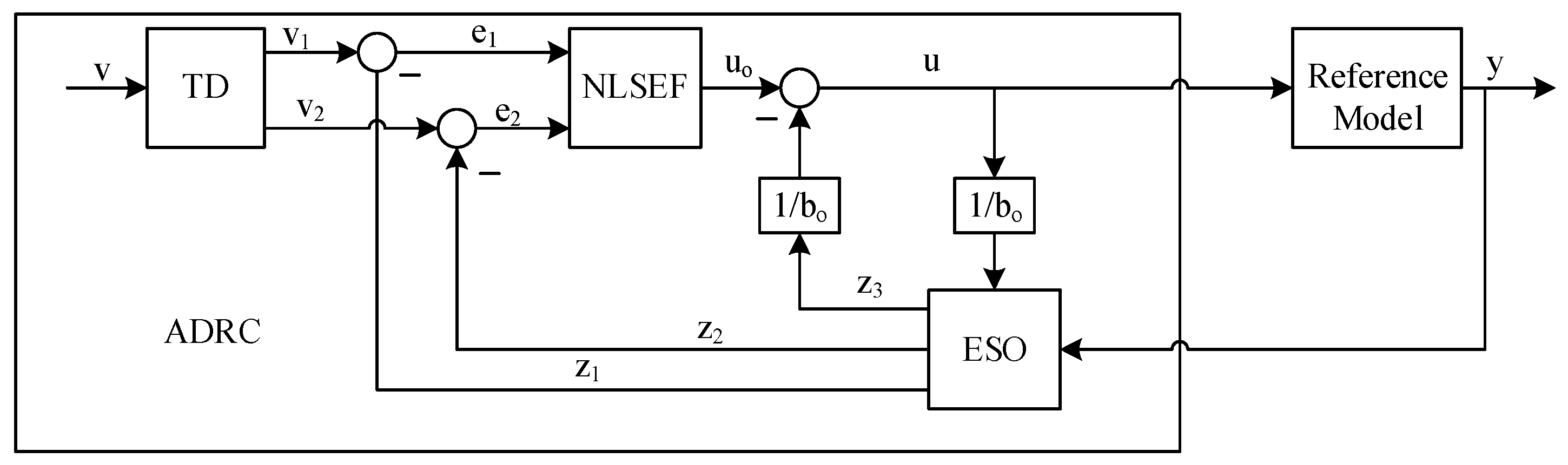
4.3. Attitude Controller
4.3.1. Tracking Differentiator
4.3.2. Extended State Observer
4.3.3. Nonlinear Law of State Error Feedback
4.4. Control Distribution
5. Simulation of Full Flight Mode
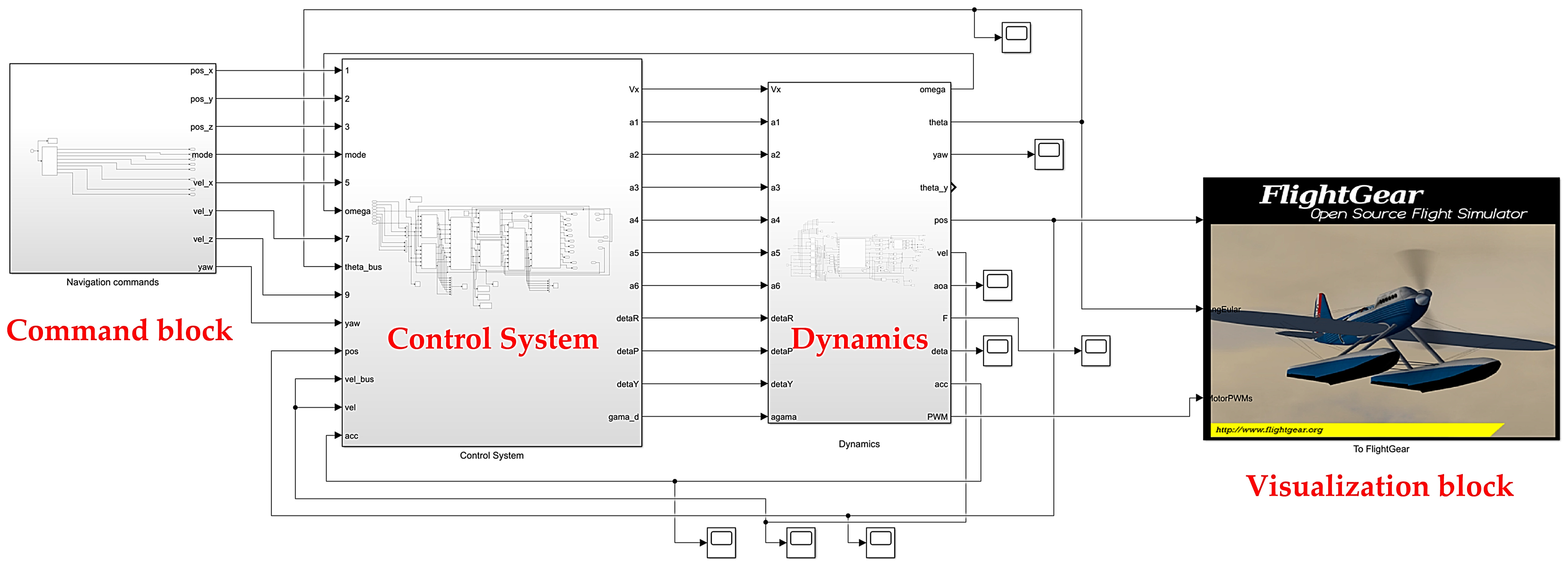
5.1. Simulation System
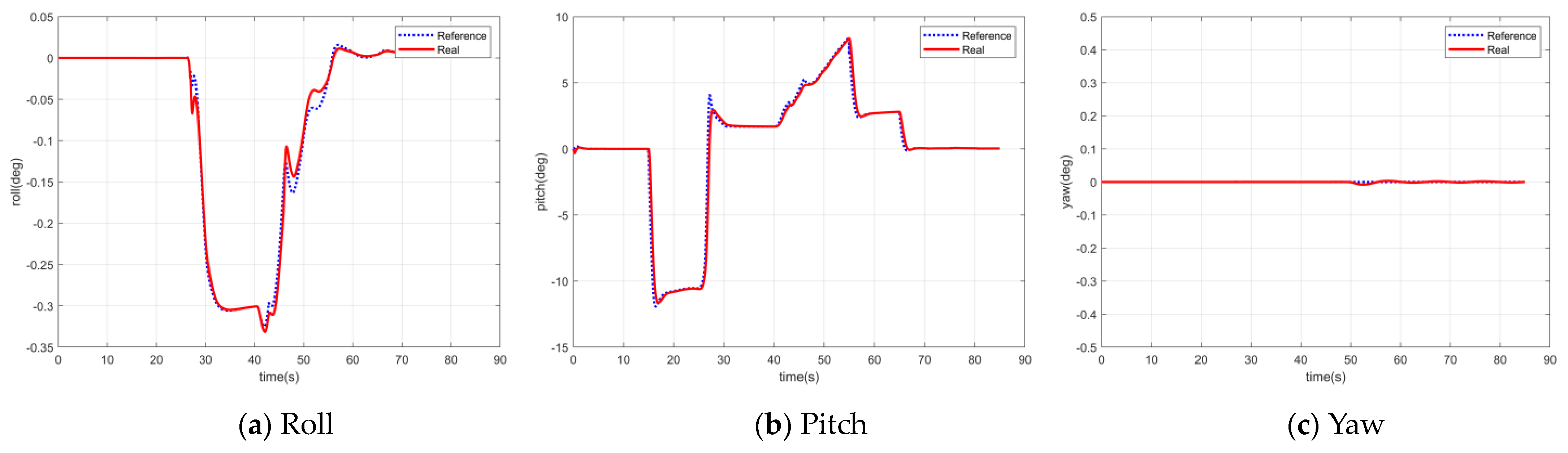
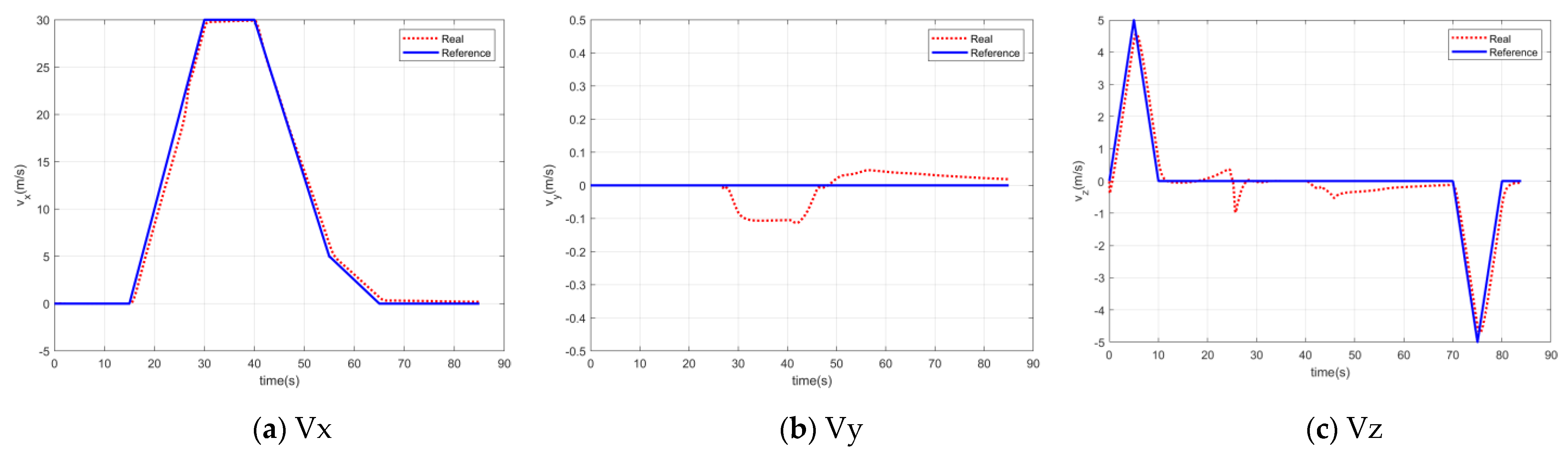
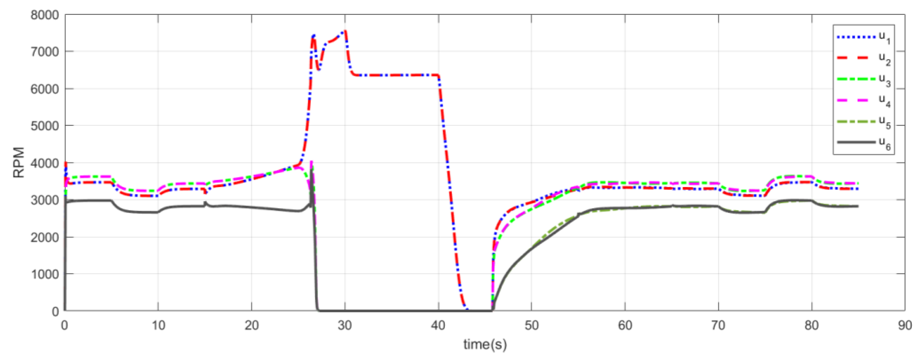
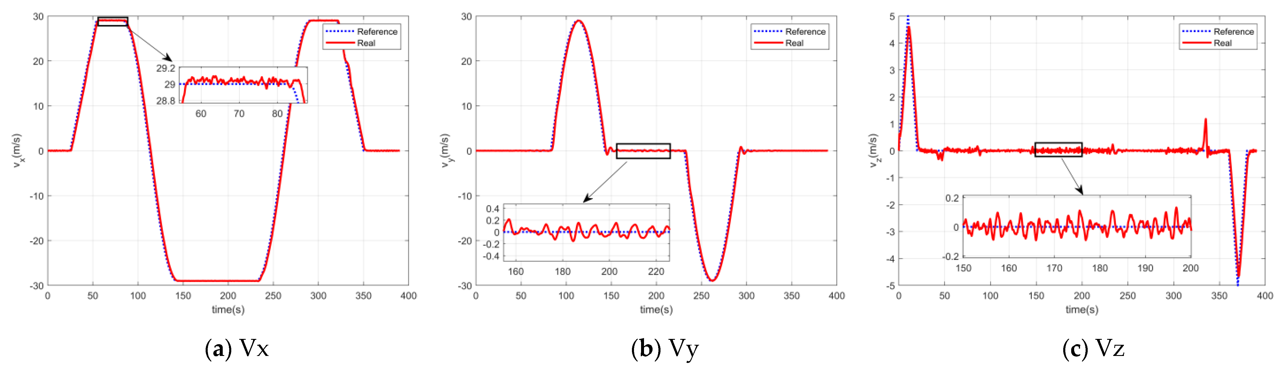
5.2. Velocity Response Control Simulation
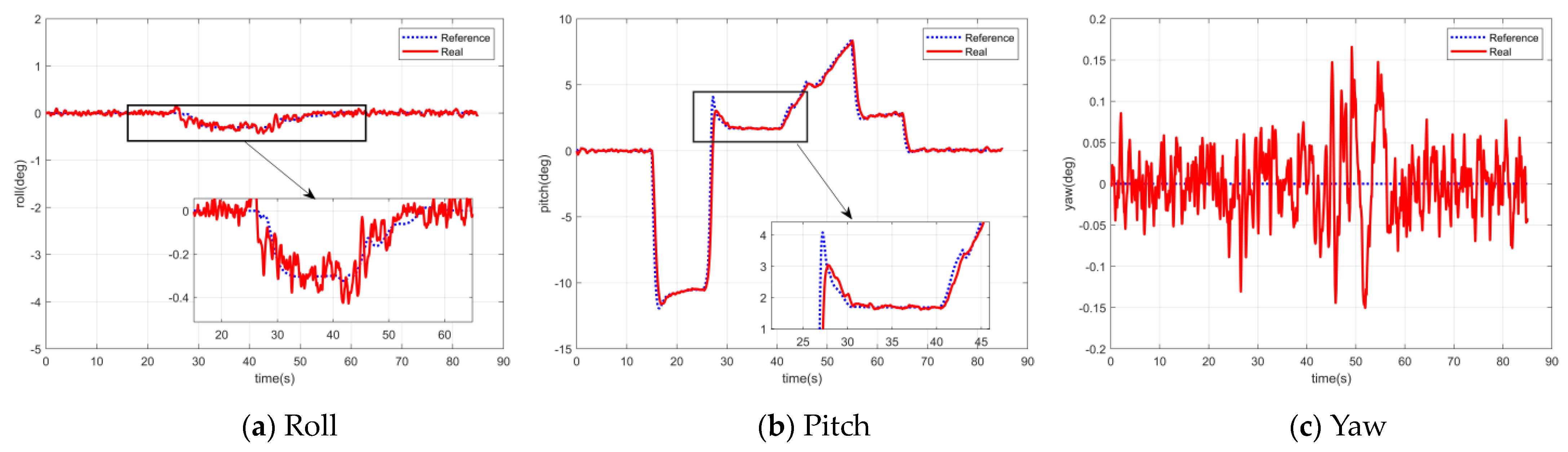
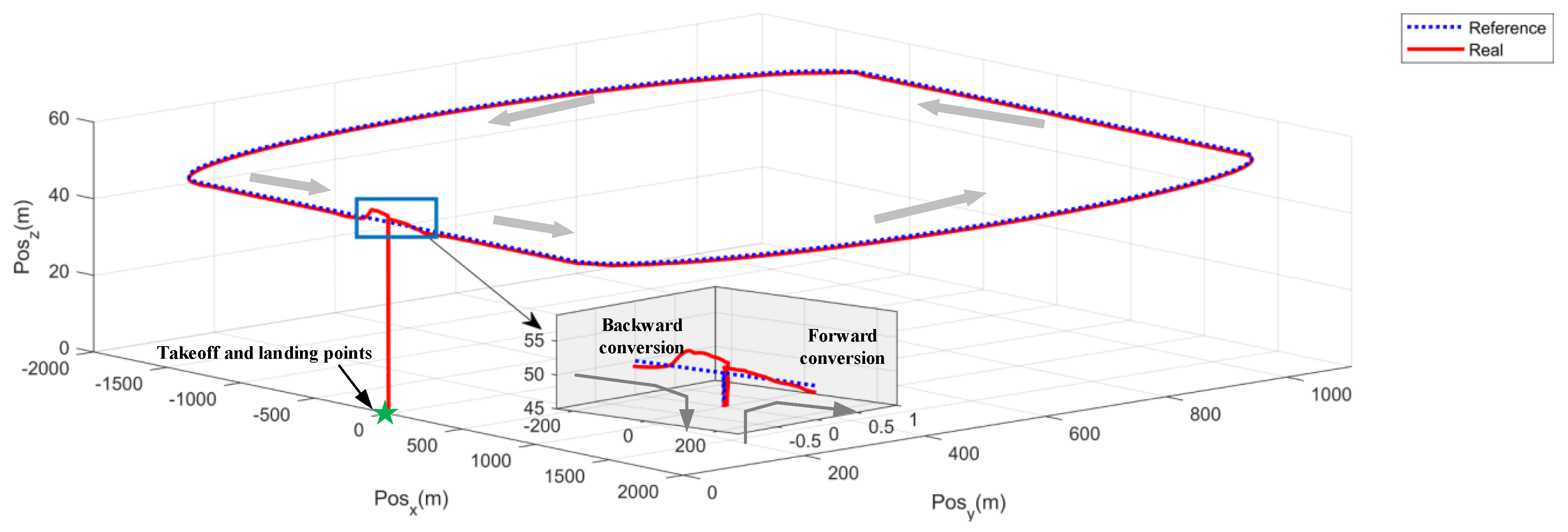
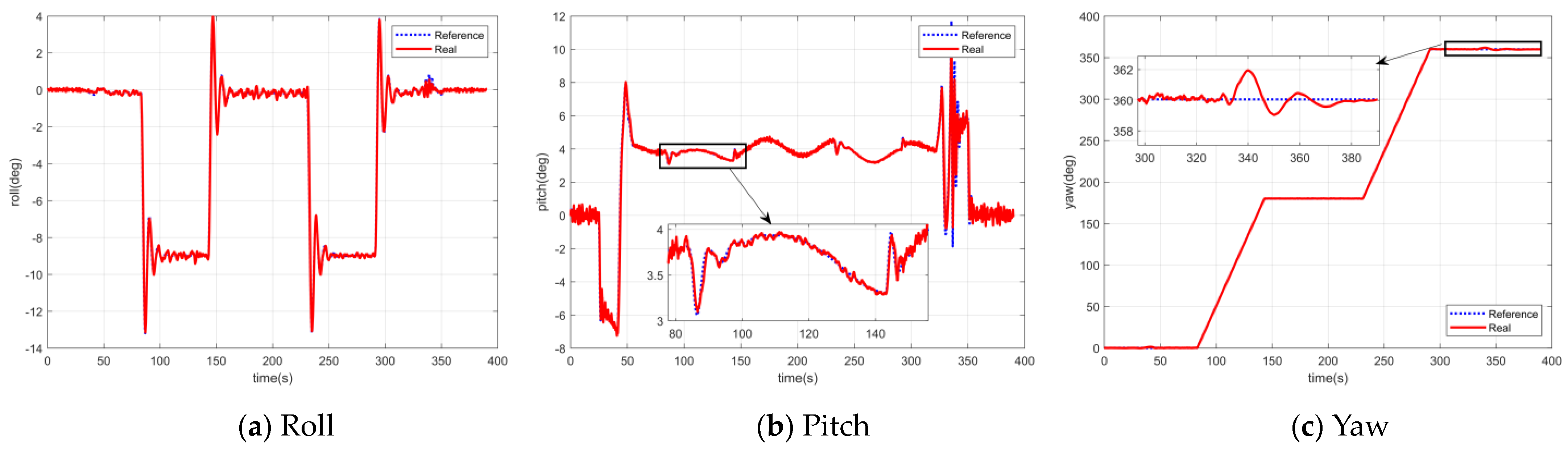
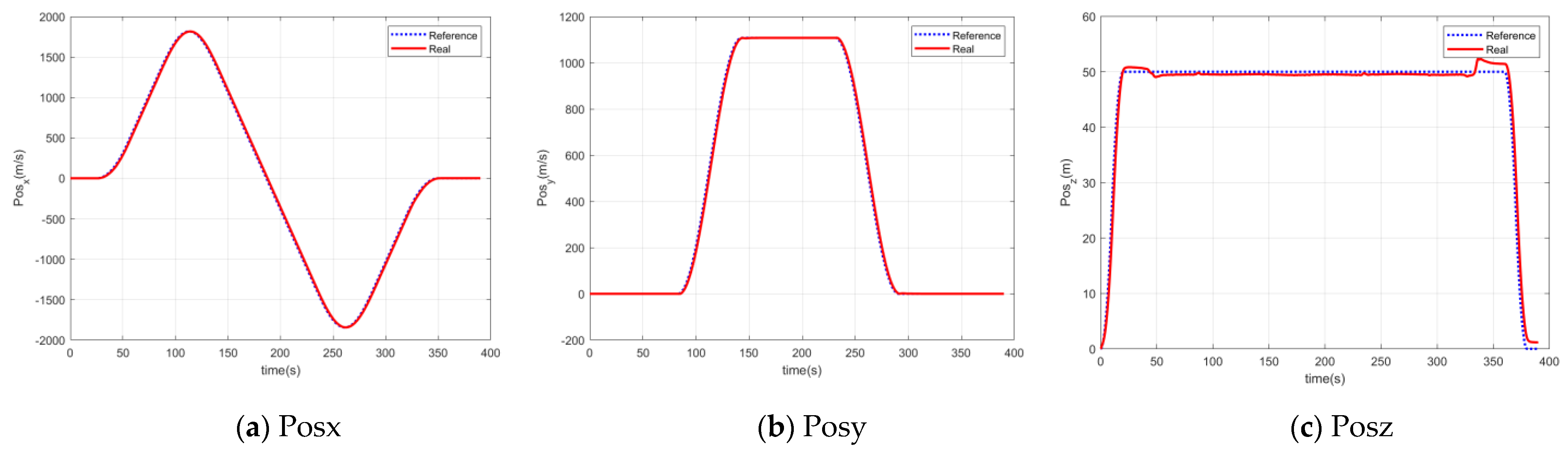
5.3. Position Mode Control Simulation
6. Conclusions
Author Contributions
Funding
Data Availability Statement
Conflicts of Interest
References
- Stolaroff, J.; Samaras, C.; Neill, E.; Lubers, A.; Mitchell, A.; Ceperley, D. Energy Use and Life Cycle Green-house Gas Emissions of Drones for Commercial Package Delivery. Nat. Commun. 2018, 9, 409. [Google Scholar] [CrossRef] [PubMed]
- Zhou, Y.; Zhao, H.; Liu, Y. An evaluative review of the VTOL technologies for unmanned and manned aerial vehicles. Comput. Commun. 2020, 149, 356–369. [Google Scholar] [CrossRef]
- Ducard, G.; Allenspach, M. Review of designs and flight control techniques of hybrid and convertible VTOL UAVs. Aerosp. Sci. Technol. 2021, 118, 107035. [Google Scholar] [CrossRef]
- Lyu, X.; Zhou, J.; Gu, H. Disturbance Observer Based Hovering Control of Quadrotor Tail-sitter VTOL UAVs Using H-infinity Synthesis. IEEE Robot. Autom. Lett. 2018, 3, 2910–2917. [Google Scholar] [CrossRef]
- Ducard, G.; Hua, M. Modeling of an unmanned hybrid aerial vehicle. In Proceedings of the 2014 IEEE Conference on Control Applications (CCA), Juan Les Antibes, France, 8–10 October 2014; pp. 1011–1016. [Google Scholar]
- Wang, H.; Cai, L. Mathematical modeling and control of a tilt-rotor aircraft. Aerosp. Sci. Technol. 2015, 47, 473–492. [Google Scholar] [CrossRef]
- Chauhan, S.; Martins, J. Tilt-Wing eVTOL Takeoff Trajectory Optimization. J. Aircr. 2019, 57, 93–112. [Google Scholar] [CrossRef]
- Li, Y.; Zhang, D.; Zhang, J. Transition flight modeling and control of a novel tilt-rotor UAV. In Proceedings of the 2017 IEEE International Conference on Information and Automation (ICIA), Macao, China, 18–20 July 2017; pp. 983–988. [Google Scholar]
- Liu, Z.; Theilliol, D.; Yang, L.; He, Y.; Han, J. Transition control of tilt rotor unmanned aerial vehicle based on multi-model adaptive method. In Proceedings of the 2017 International Conference on Unmanned Aircraft Systems (ICUAS), Miami, FL, USA, 13–16 June 2017; pp. 560–566. [Google Scholar]
- Shen, Z.; Peng, T.; Qiu, L. Design of Flight Control Law for Tiltrotor Aircraft Based on Incremental Dynamic Inversion. Acta Armamentaria 2019, 40, 10. (In Chinese) [Google Scholar]
- Wang, Z.; Li, J.; Duan, D. Manipulation strategy of tilt quad rotor based on active disturbance rejection control. Proc. Inst. Mech. Eng. Part G J. Aerosp. Eng. 2020, 234, 573–584. [Google Scholar] [CrossRef]
- Allenspach, M.; Ducard, G. Model Predictive Control of a Convertible Tiltrotor Unmanned Aerial Vehicle. In Proceedings of the 2020 28th Mediterranean Conference on Control and Automation (MED), Saint-Raphaël, France, 15–18 September 2020; pp. 715–720. [Google Scholar]
- Allenspach, M.; Ducard, G. Nonlinear model predictive control and guidance for a propeller-tilting hybrid unmanned air vehicle. Automatica 2021, 132, 109790. [Google Scholar] [CrossRef]
- Bauersfeld, L.; Spannagl, L.; Ducard, G. MPC Flight Control for a Tilt-rotor VTOL Aircraft. IEEE Trans. Aerosp. Electron. Syst. 2021, 57, 2395–2409. [Google Scholar] [CrossRef]
- Yin, Y.; Niu, H.; Liu, X. Adaptive Neural Network Sliding Mode Control for Quad Tilt Rotor Aircraft. Complexity 2017, 2017, 7104708. [Google Scholar] [CrossRef]
- Liao, J.; Bang, H. Transition Nonlinear Blended Aerodynamic Modeling and Anti-Harmonic Disturbance Robust Control of Fixed-Wing Tiltrotor UAV. Drones 2023, 7, 255. [Google Scholar] [CrossRef]
- Mousaei, M.; Geng, J.; Keipour, A.; Bai, D.; Scherer, S. Design, Modeling and Control for a Tilt-rotor VTOL UAV in the Presence of Actuator Failure. In Proceedings of the 2022 IEEE/RSJ International Conference on Intelligent Robots and Systems (IROS), Kyoto, Japan, 23–27 October 2022; pp. 4310–4317. [Google Scholar]
- Xu, J.; Du, T.; Foshey, M. Learning to fly: Computational controller design for hybrid UAVs with reinforcement learning. ACM Trans. Graph. 2019, 38, 1–12. [Google Scholar] [CrossRef]
- Liebeck, R. Design of Subsonic Airfoils for High Lift. J. Aircraft. J. Aircr. 1978, 15, 547–561. [Google Scholar] [CrossRef]
- Cebeci, T.; Chen, H.; Liebeck, R.; Mcilvaine, M. Calculation of low Reynolds number flows at high angles of attack. J. Aircr. 1991, 28, 246–252. [Google Scholar] [CrossRef]
- Wang, S.; Guo, Z. Low speed airfoil optimization based on evolutionary algorithm and composite parameterization method. Phys. Gases 2022, 7, 63–70. [Google Scholar]
- Young, J. Propeller at high incidence. J. Aircr. 1965, 2, 241. [Google Scholar] [CrossRef]
- Tangler, J.; Ostowari, C. Horizontal axis wind turbine post stall airfoil characteristics synthesization. In Proceedings of the Wind Turbine Technology, Cleveland, OH, USA, 8–10 May 1984. [Google Scholar]
- Viterna, L.; Corrigan, R. Fixed pitch rotor performance of large horizontal axis wind turbines. In Large Horizontal-Axis Wind Tur-Bines; NASA-CP-2230; NASA Conference Publication: Washington, DC, USA, 1982; pp. 69–86. [Google Scholar]
- Px4 Firmware. Available online: https://github.com/PX4/Firmware/tree/master/src/modules (accessed on 14 May 2023).
- Mellinger, D.; Kumar, V. Minimum snap trajectory generation and control for quadrotors. In Proceedings of the 2011 IEEE International Conference on Robotics and Automation, Shanghai, China, 9–13 May 2011; pp. 2520–2525. [Google Scholar]
- Park, S.; Deyst, J.; How, J. A new nonlinear guidance logic for trajectory tracking. In Proceedings of the AIAA Guidance, Navigation, and Control Conference and Exhibit, Providence, RI, USA, 16–19 August 2004; p. 4900. [Google Scholar]
- Bauersfeld, L.; Ducard, G. Fused-PID Control for Tilt-Rotor VTOL Aircraft. In Proceedings of the 2020 28th Mediterranean Conference on Control and Automation (MED), Saint-Raphaë, France, 15–18 September 2020; pp. 703–708. [Google Scholar]
- Han, J. From PID to Active Disturbance Rejection Control. IEEE Trans. Ind. Electron. 2009, 56, 900–906. [Google Scholar] [CrossRef]
- Spannagl, L.; Ducard, G. Control Allocation for an Unmanned Hybrid Aerial Vehicle. In Proceedings of the 2020 28th Mediterranean Conference on Control and Automation (MED), Saint-Raphaël, France, 15–18 September 2020; pp. 709–714. [Google Scholar]
- FlightGear. Available online: https://www.flightgear.org (accessed on 18 October 2023).
- APC. Available online: www.apcprop.com (accessed on 27 December 2016).
- Xu, Z.; Fan, L.; Qiu, W.; Wen, G.; He, Y. A Robust Disturbance-Rejection Controller Using Model Predictive Control for Quadrotor UA V in Tracking Aggressive Trajectory. Drones 2023, 7, 557. [Google Scholar] [CrossRef]
- Shen, S.; Xu, J.; Chen, P.; Xia, Q. Adaptive Neural Network Extended State Observer-Based Finite-Time Convergent Sliding Mode Control for a Quad Tiltrotor UAV. IEEE Trans. Aerosp. Electron. Syst. 2023, 59, 6360–6373. [Google Scholar] [CrossRef]


| Parameter | Description | Value |
|---|---|---|
| m | Mass | 31.2 kg |
| b | Wingspan | 2.7265 m |
| Air density | 1.2250 kg/ | |
| Mean chord | 0.280922 m | |
| S | Wing surface area | 0.783078 |
| Design cruise velocity | 29.6 m/s |
| Parameter | PID of Velocity Loop | Parameter | ADRC |
|---|---|---|---|
| (1.2 1.2 0.8) | r | (20 10 20) | |
| (0.02 0.01 0.01) | h | (0.01 0.01 0.01) | |
| (0.001 0.001 0.001) | (30 30 40) | ||
| (0.25 0.25 0.15) | (200 100 50) | ||
| (0.03 0.02 0.02) | (10 5 5) | ||
| (0.001 0.001 0.001) | (200 200 100) | ||
| (1000 1000 500) | |||
| (50 50 25) |
| Parameter | PID of Position Loop | Parameter | PID of Velocity Loop | Parameter | ADRC |
|---|---|---|---|---|---|
| (0.8 0.8 0.6) | (1.2 1.2 0.8) | r | (20 10 20) | ||
| (0 0 0) | (0.02 0.01 0.01) | h | (0.01 0.01 0.01) | ||
| (0.001 0.001 0.001) | (0.001 0.001 0.001) | (30 30 40) | |||
| (0.7 0.8 0.4) | (0.25 0.25 0.15) | (200 100 50) | |||
| (0 0 0) | (0.03 0.02 0.02) | (10 5 5) | |||
| (0.001 0.001 0.001) | (0.001 0.001 0.001) | (200 200 100) | |||
| (1000 1000 500) | |||||
| (50 50 25) |
Disclaimer/Publisher’s Note: The statements, opinions and data contained in all publications are solely those of the individual author(s) and contributor(s) and not of MDPI and/or the editor(s). MDPI and/or the editor(s) disclaim responsibility for any injury to people or property resulting from any ideas, methods, instructions or products referred to in the content. |
© 2024 by the authors. Licensee MDPI, Basel, Switzerland. This article is an open access article distributed under the terms and conditions of the Creative Commons Attribution (CC BY) license (https://creativecommons.org/licenses/by/4.0/).
Share and Cite
Liang, Z.; Fan, L.; Wen, G.; Xu, Z. Design, Modeling, and Control of a Composite Tilt-Rotor Unmanned Aerial Vehicle. Drones 2024, 8, 102. https://doi.org/10.3390/drones8030102
Liang Z, Fan L, Wen G, Xu Z. Design, Modeling, and Control of a Composite Tilt-Rotor Unmanned Aerial Vehicle. Drones. 2024; 8(3):102. https://doi.org/10.3390/drones8030102
Chicago/Turabian StyleLiang, Zhuang, Li Fan, Guangwei Wen, and Zhixiong Xu. 2024. "Design, Modeling, and Control of a Composite Tilt-Rotor Unmanned Aerial Vehicle" Drones 8, no. 3: 102. https://doi.org/10.3390/drones8030102