
Optimization-Based Control for a Large-Scale Electrical Vertical Take-Off and Landing during an Aircraft’s Vertical Take-Off and Landing Phase with Variable-Pitch Propellers


Abstract
:1. Introduction
- A typical tail-sitter eVTOL platform with distributed variable-pitch propellers is designed, which is able to achieve excellent flying performances during both the VTOL and cruise phase. Simulation data of the platform are then utilized as the objective for the designed controller with nonlinear flight dynamics. In addition, an actuator system consisting of four variable-pitch propellers is designed and its thrust and torque models are accurately analyzed.
- A specific optimization-based control allocation module is achieved to fully excavate the control potential of the variable-pitch propellers with four extra control variables, and the control allocation solution can be generated with low-dimensional quadratic programming solvers.
- This module is then mounted in a complete control system including position and attitude controllers to track the given trajectory. Constraints such as power consumption and the maximum rate of the control variables are considered to maintain the stability of the system.
- A series of simulation experiments are accomplished in order to validate the effectiveness of the designed controller under different circumstances, such as set-point arrival and aggressive trajectory tracking under measurement noise and external disturbances.
2. System Design and Flight Dynamics Analysis
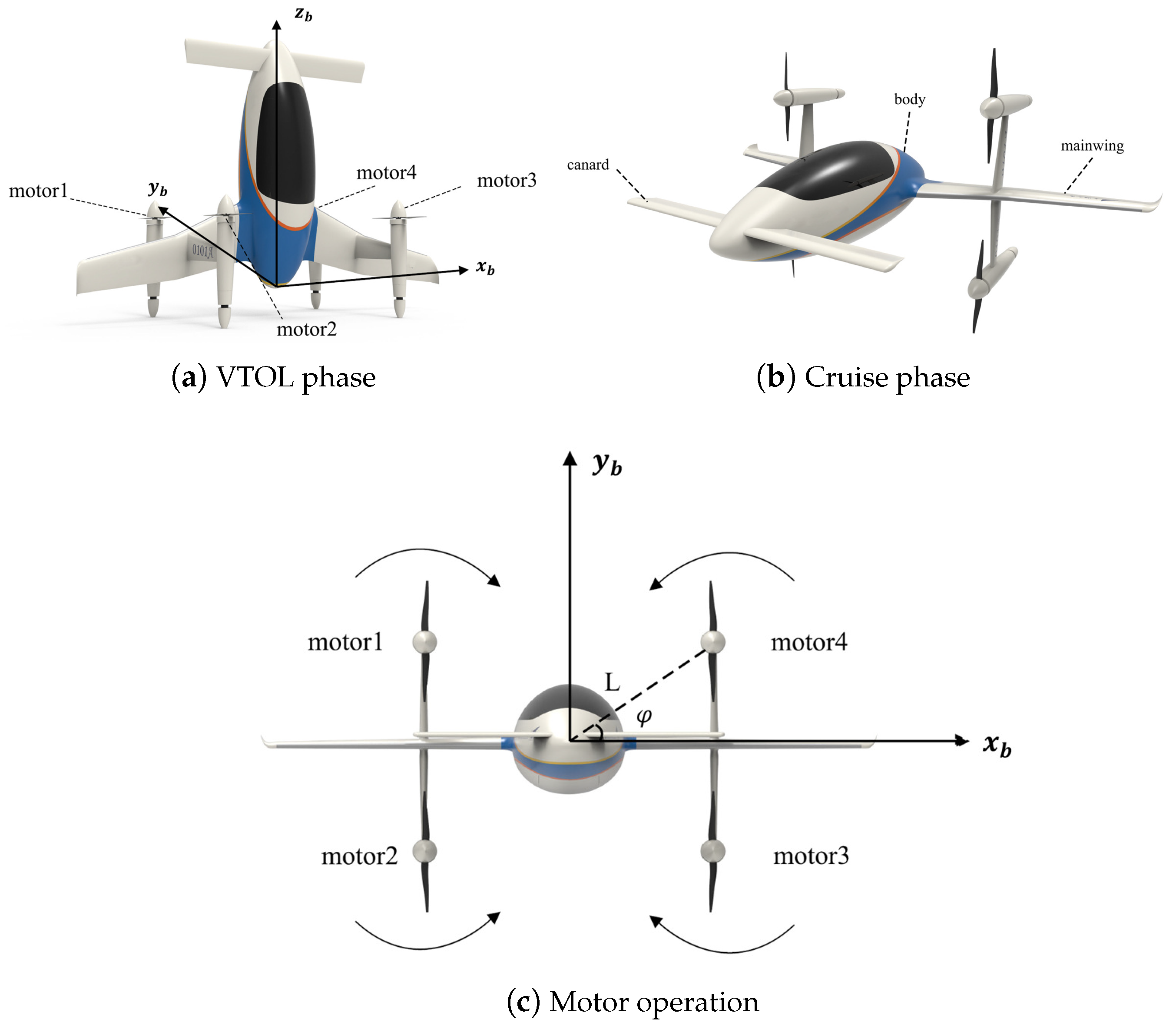
2.1. Platform Introduction and Frame Description
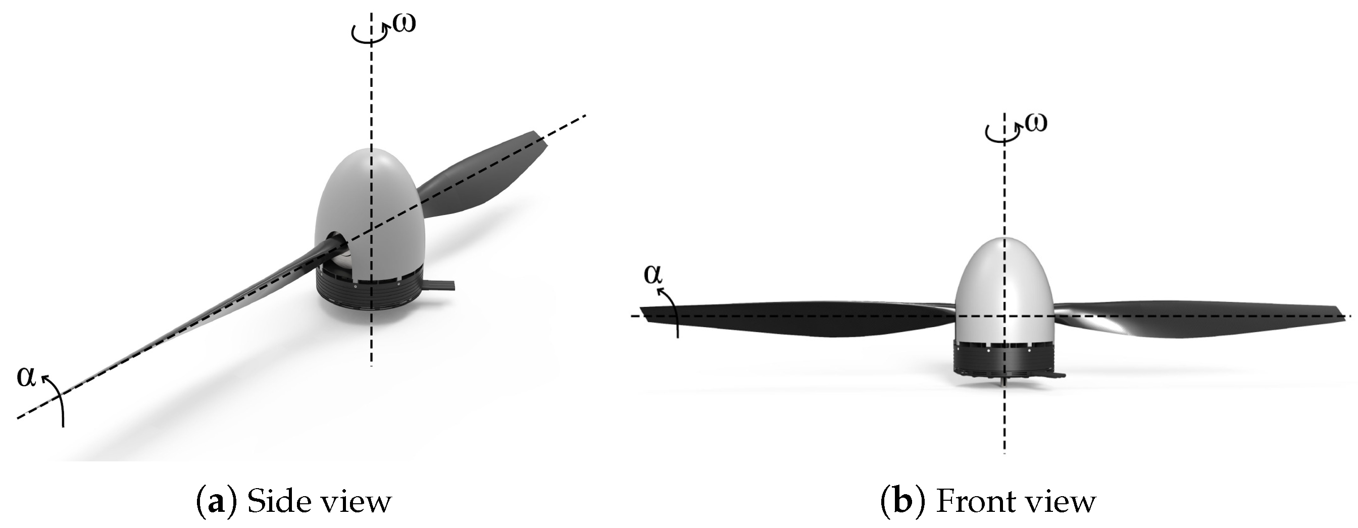
2.2. Variable-Pitch Propeller Design and Analysis
2.2.1. Propeller System Design
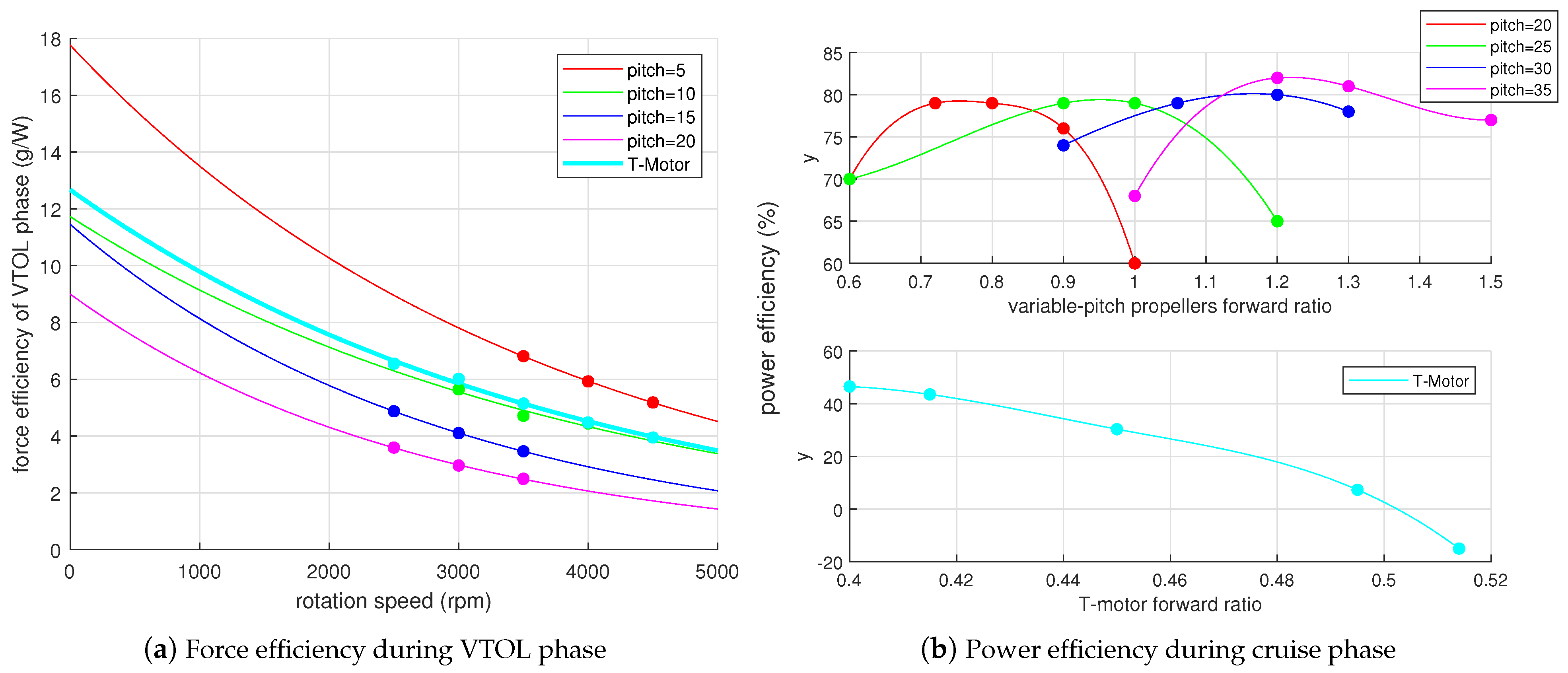
2.2.2. Efficiency Analysis
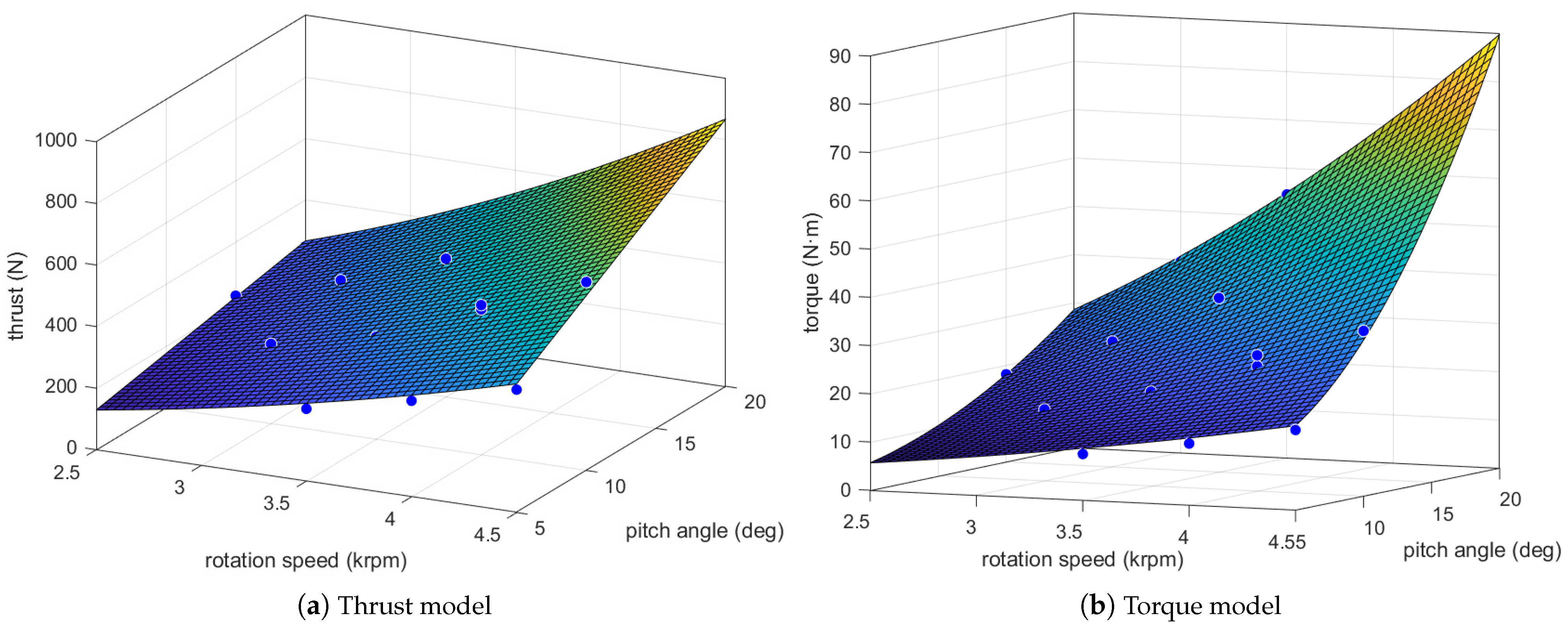
2.2.3. Propulsion System Model Analysis
2.3. Aircraft Dynamics and Differential Flatness Property
3. Control Law Design
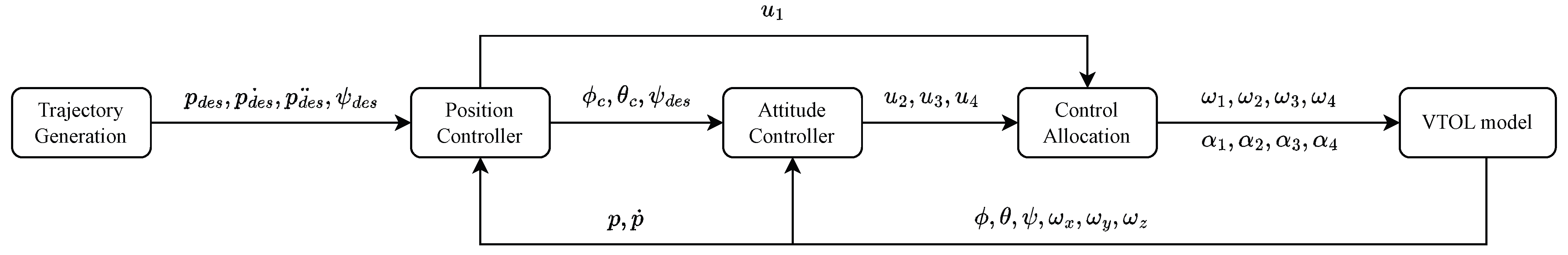
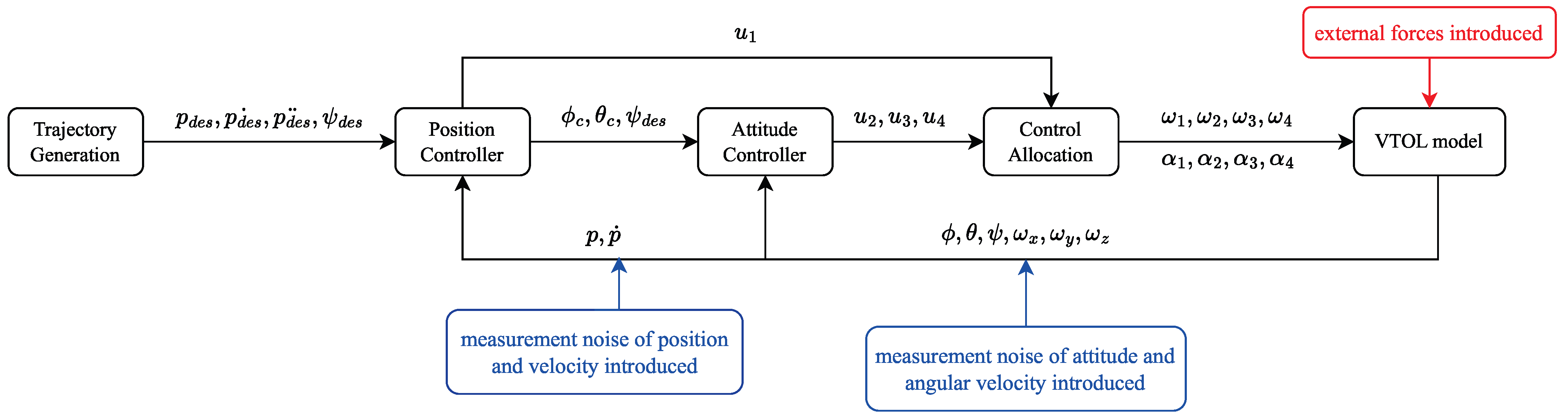
3.1. Control System Overview
3.2. Penalty Function Construction
3.2.1. Control Inputs’ Penalty
3.2.2. Control Variables’ Shifting Penalty
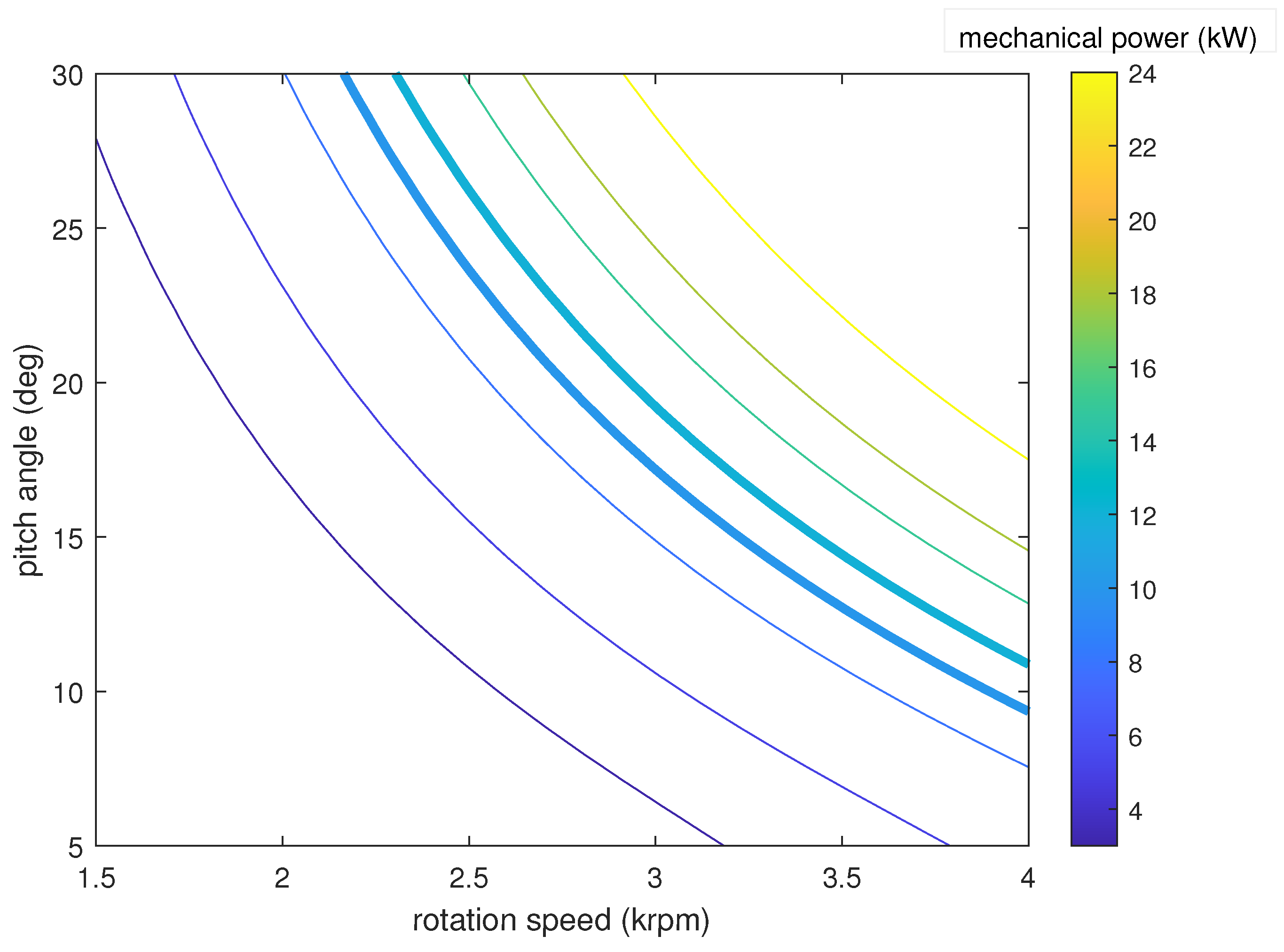
3.2.3. Energy Consumption Penalty
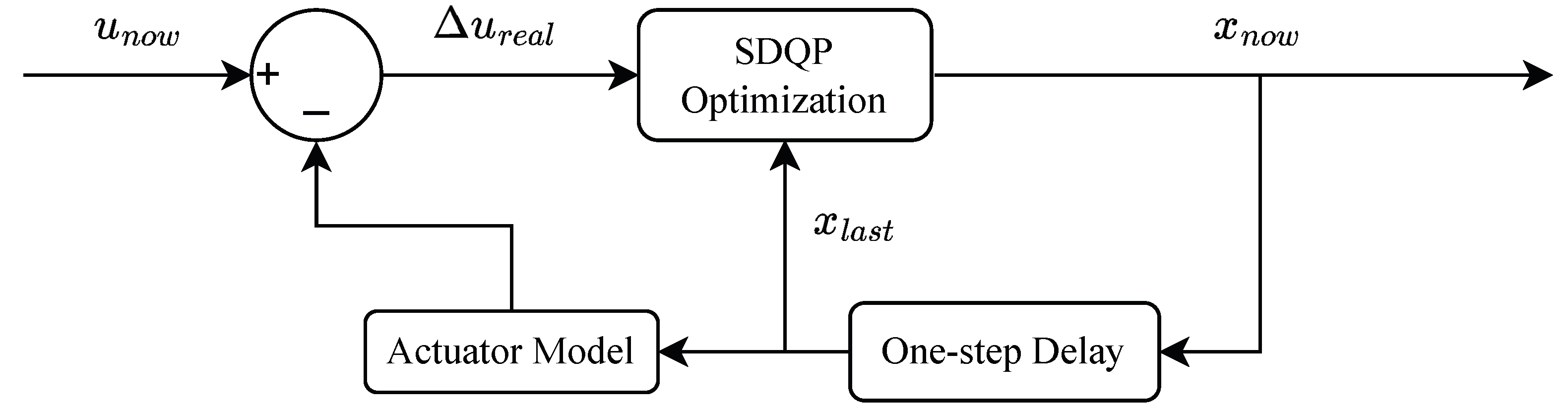
3.3. Optimization-Based Control Allocation Algorithm
4. Simulation Experiments
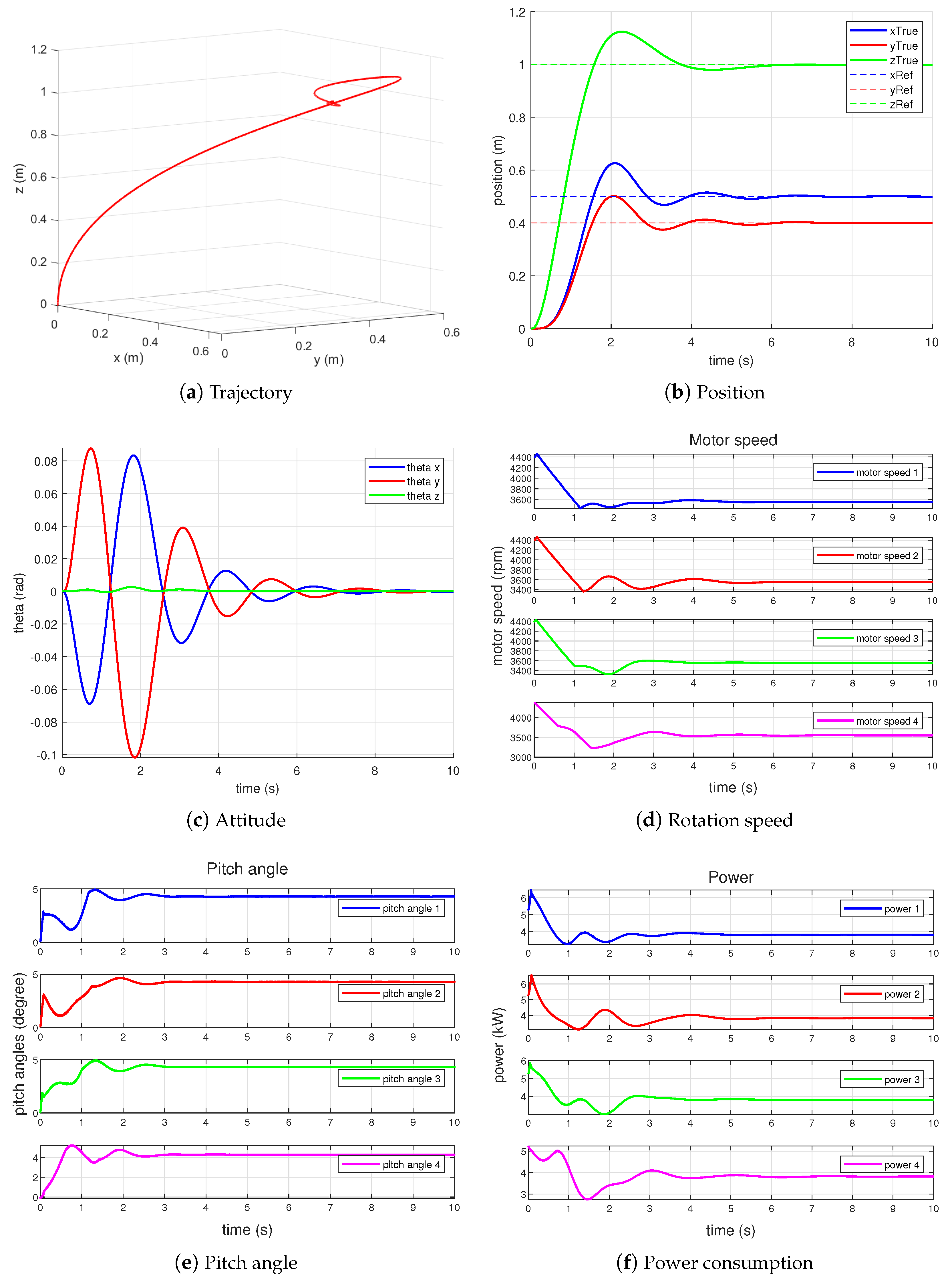
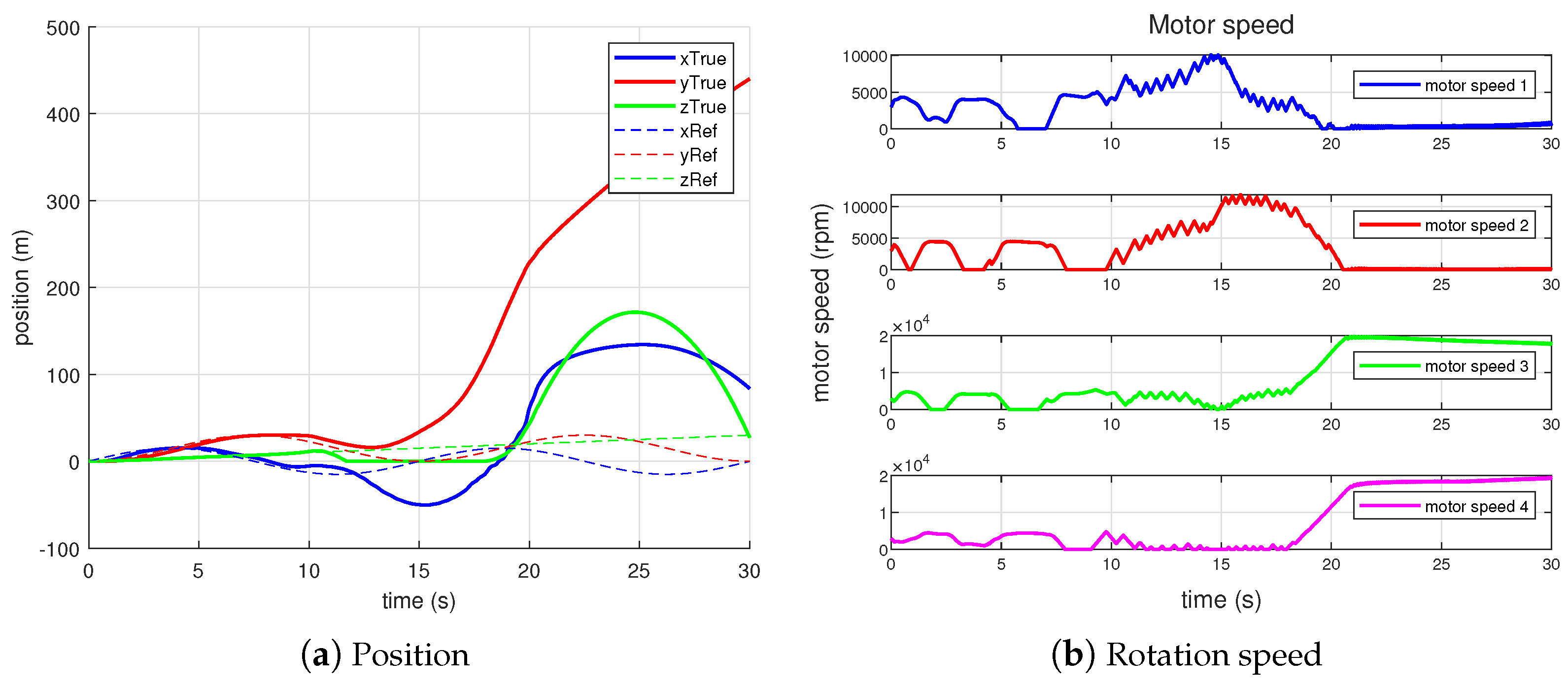
4.1. Set-Point Control
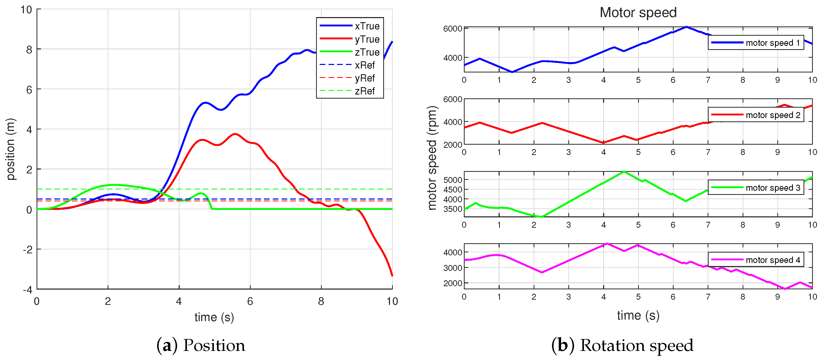
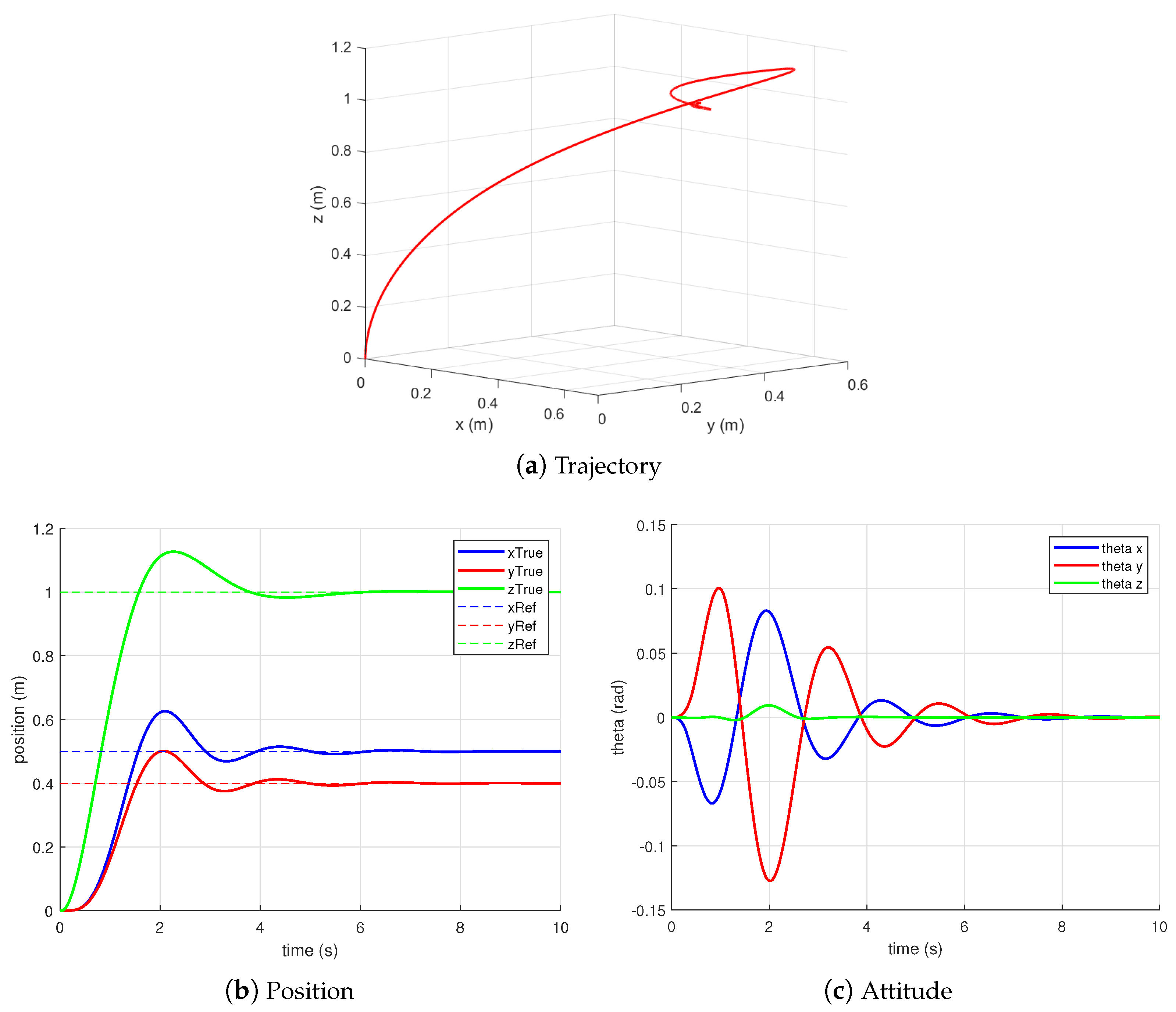
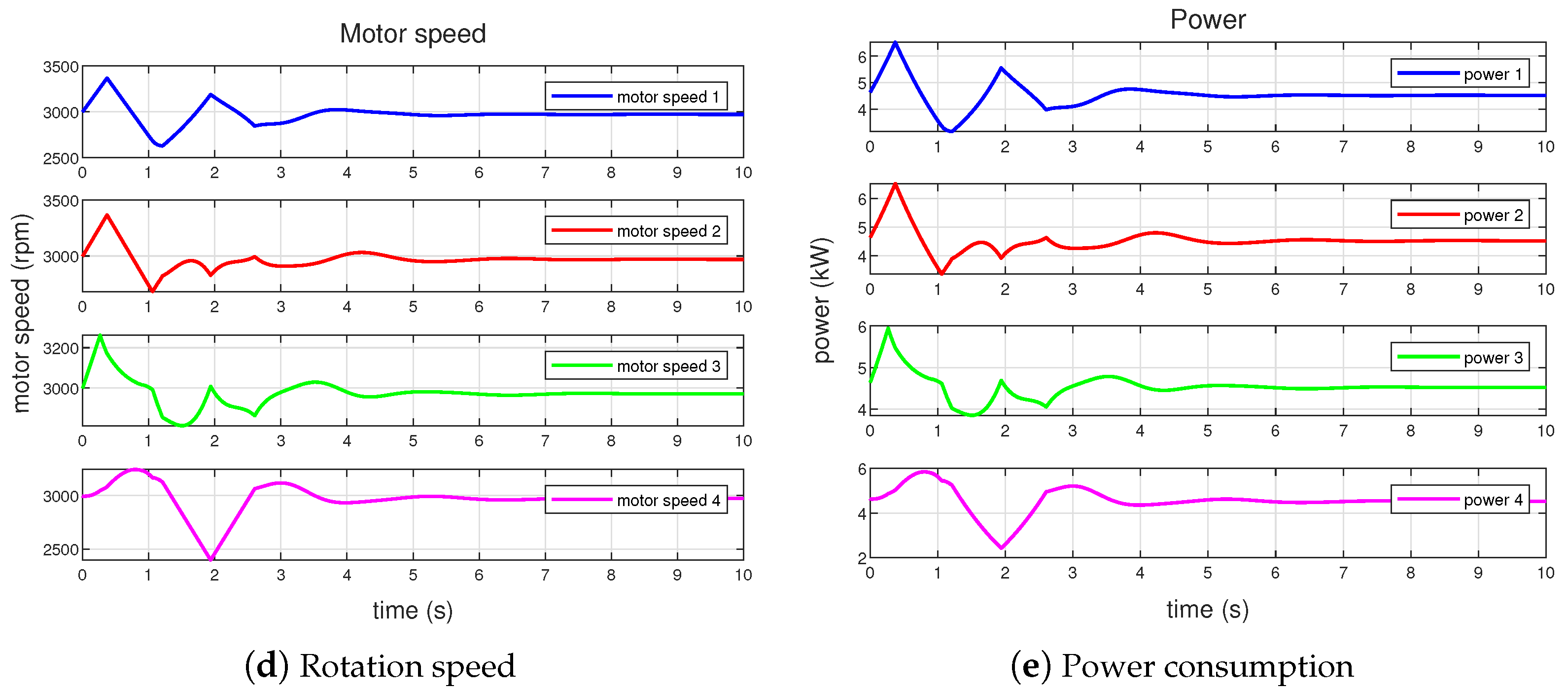
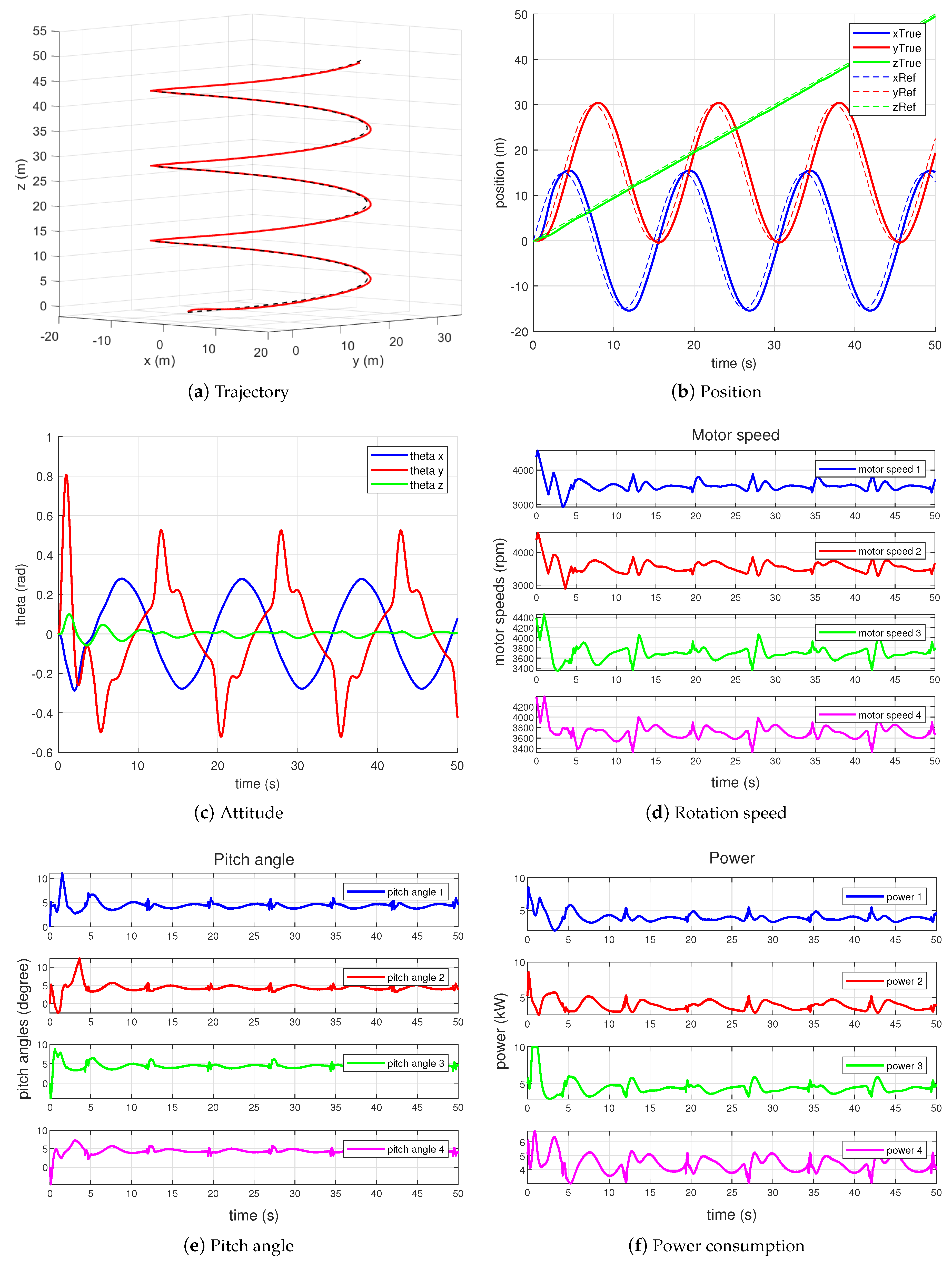
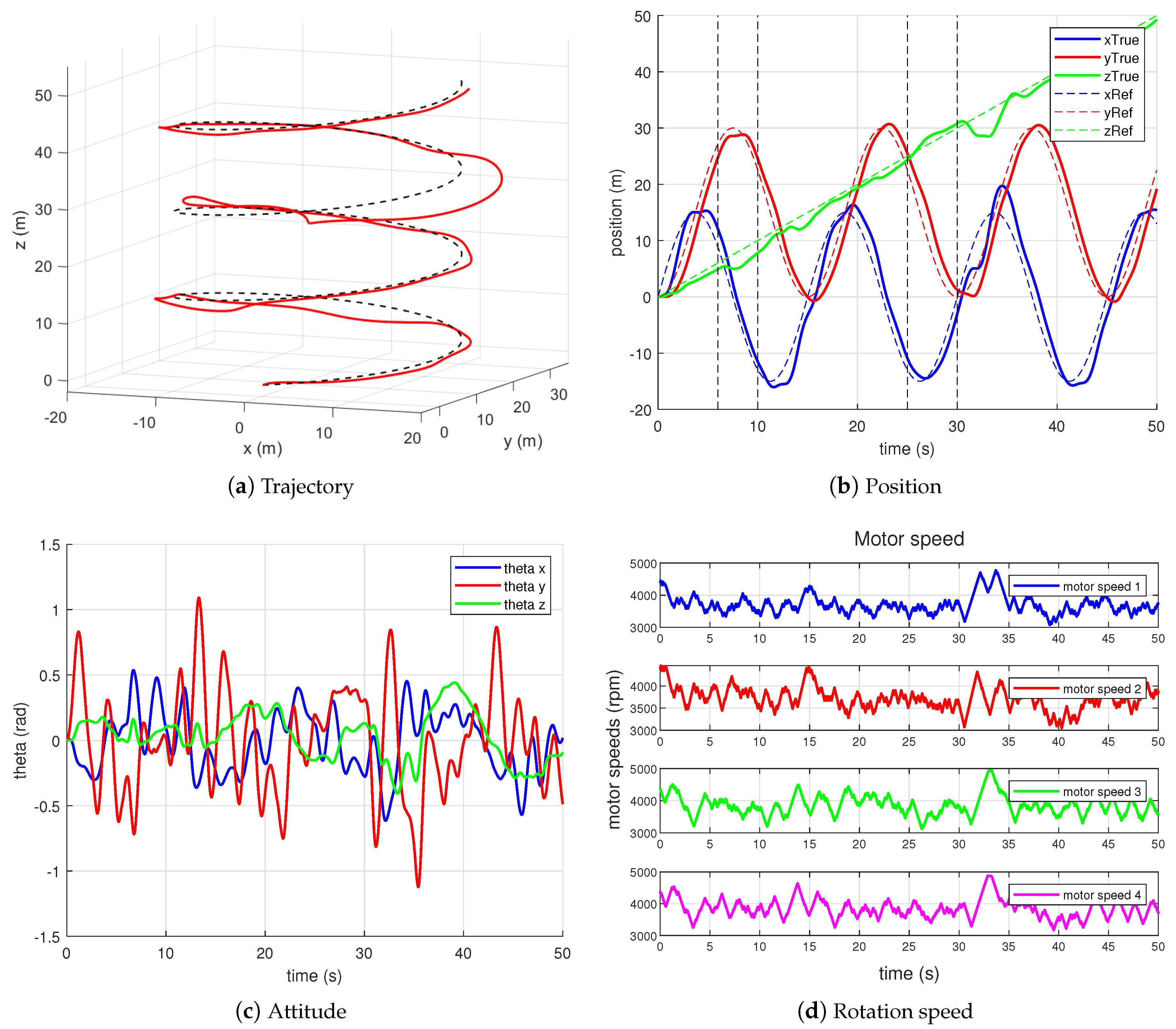
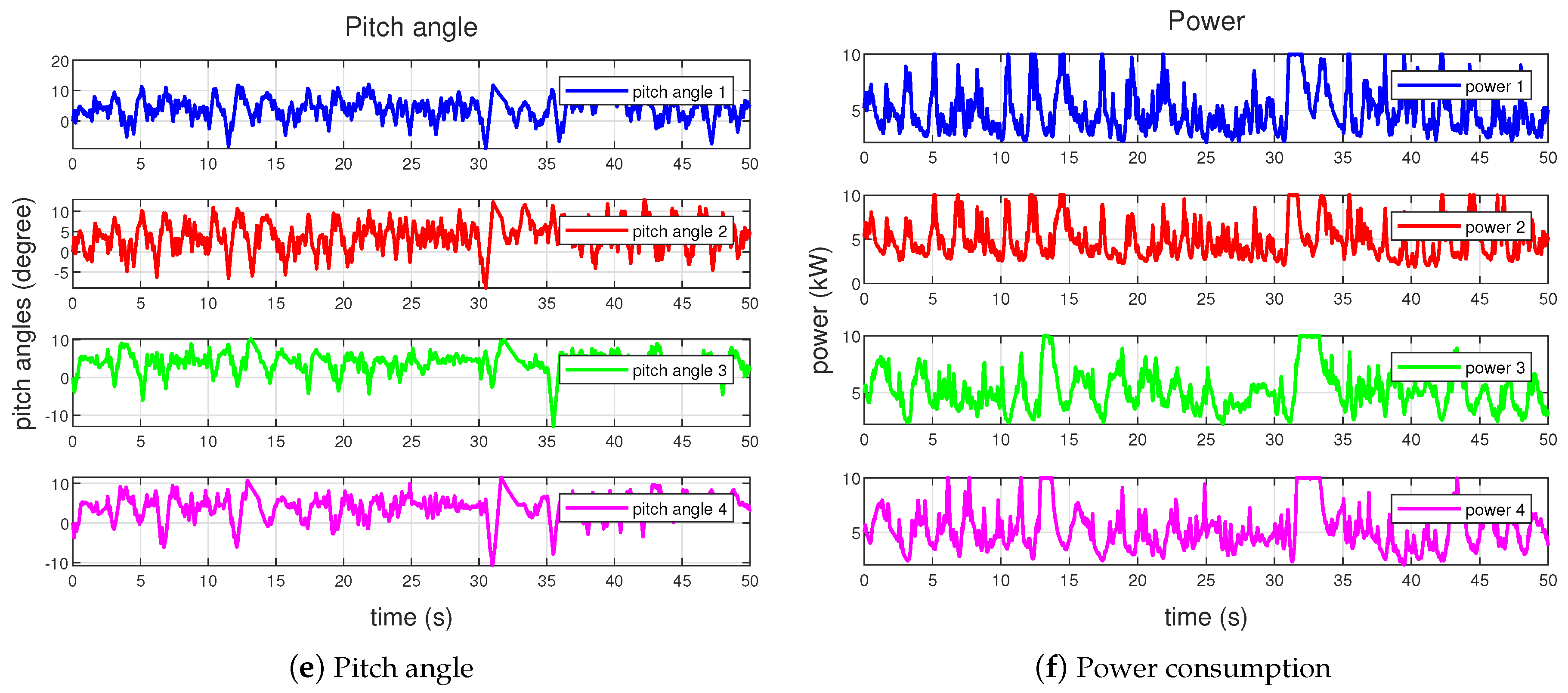
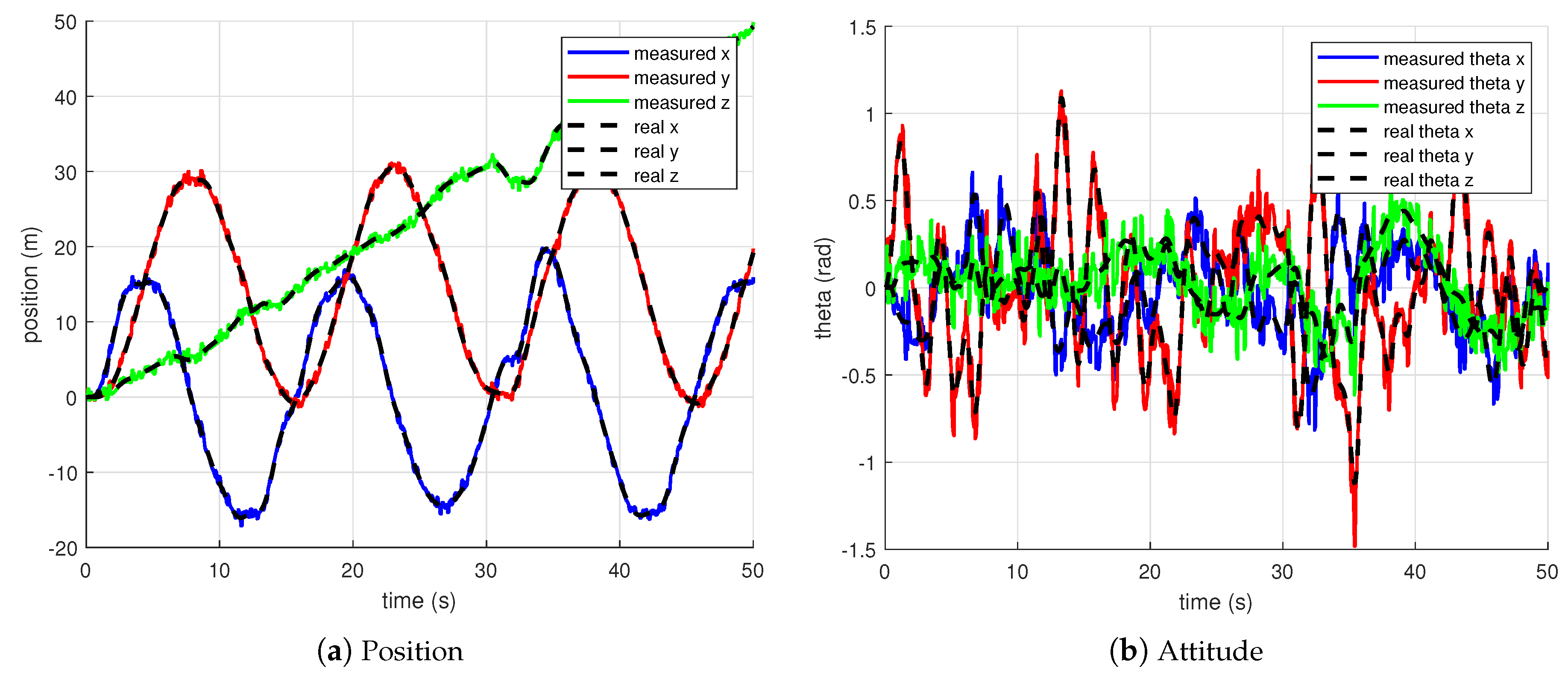
4.2. Aggressive Trajectory Tracking
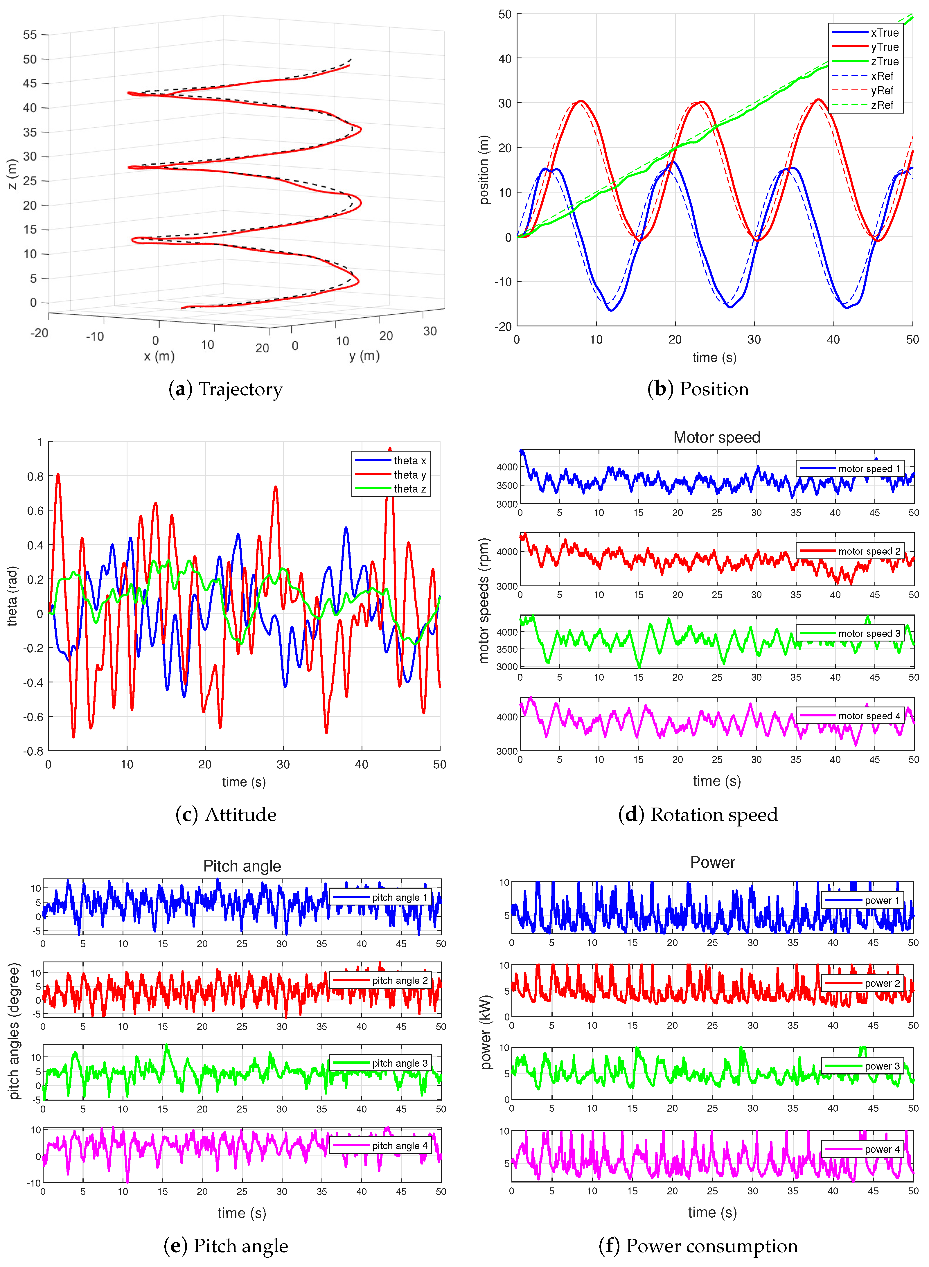
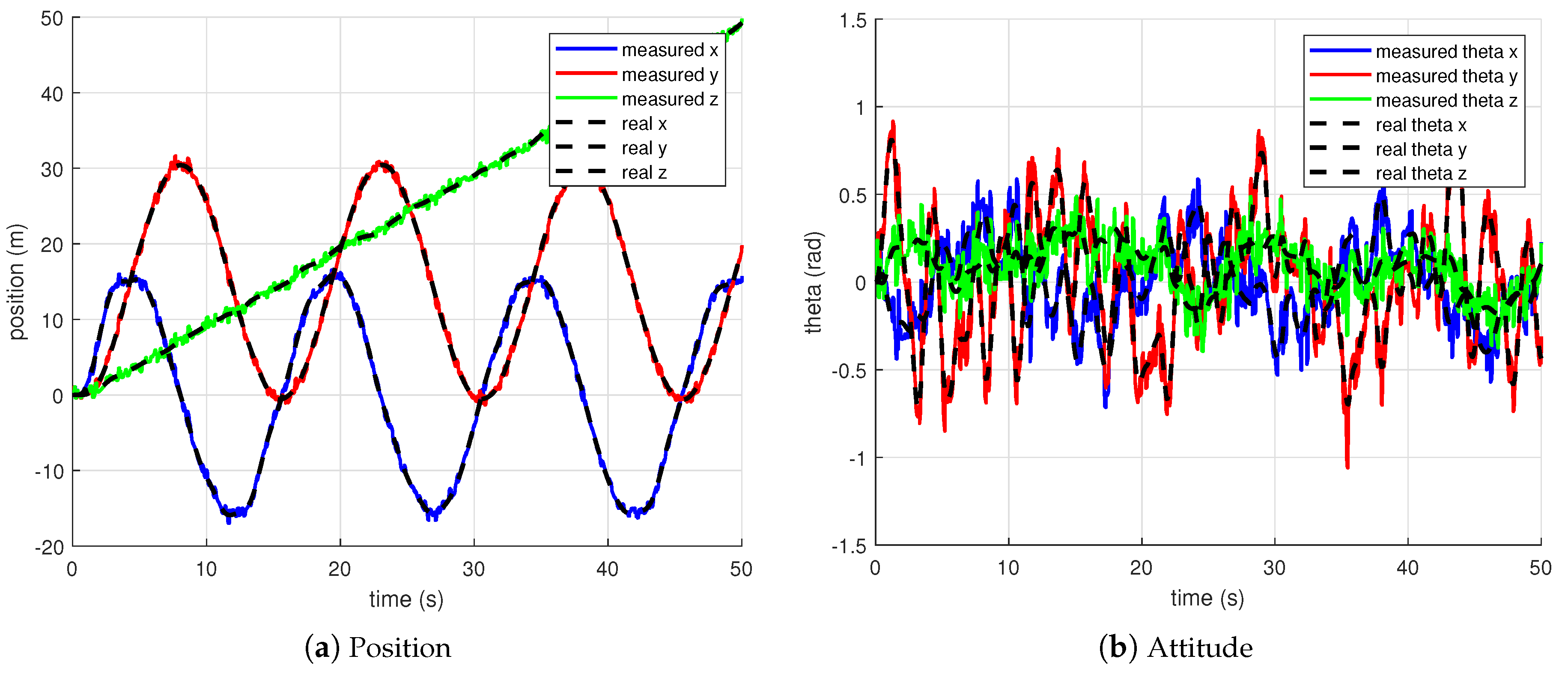
4.3. Flying under Measurement Noise and External Disturbances
4.4. Numerical Analysis
4.4.1. Set-Point Control
4.4.2. Aggressive Trajectory Control
5. Conclusions
Author Contributions
Funding
Data Availability Statement
Conflicts of Interest
References
- Schumacher, L.; McNamee, P.I.; Haug, J.; Barrett, R. Development of a safe, quiet, certifiable personal vtol system. In Proceedings of the AIAA Aviation 2019 Forum, Dallas, TX, USA, 17–21 June 2019; p. 3475. [Google Scholar]
- Gu, H.; Lyu, X.; Li, Z.; Shen, S.; Zhang, F. Development and experimental verification of a hybrid vertical take-off and landing (VTOL) unmanned aerial vehicle (UAV). In Proceedings of the 2017 International Conference on Unmanned Aircraft Systems (ICUAS), Miami, FL, USA, 13–16 June 2017; pp. 160–169. [Google Scholar]
- Cetinsoy, E. Design and modeling of a gas-electric hybrid quad tilt-rotor UAV with morphing wing. In Proceedings of the 2014 IEEE International Conference on Mechatronics and Automation, Tianjin, China, 3–6 August 2014; pp. 1193–1198. [Google Scholar]
- Carlson, S. A hybrid tricopter/flying-wing vtol uav. In Proceedings of the 52nd Aerospace Sciences Meeting, National Harbor, MD, USA, 13–17 January 2014; p. 0016. [Google Scholar]
- Dickeson, J.J.; Miles, D.; Cifdaloz, O.; Wells, V.L.; Rodriguez, A.A. Robust lpv h gain-scheduled hover-to-cruise conversion for a tilt-wing rotorcraft in the presence of cg variations. In Proceedings of the 2007 American Control Conference, New York, NY, USA, 9–13 July 2007; pp. 5266–5271. [Google Scholar]
- Çetinsoy, E.; Sirimoğlu, E.; Öner, K.T.; Hancer, C.; Ünel, M.; Akşit, M.F.; Kandemir, I.; Gülez, K. Design and development of a tilt-wing UAV. Turk. J. Electr. Eng. Comput. Sci. 2011, 19, 733–741. [Google Scholar] [CrossRef]
- Lu, G.; Cai, Y.; Chen, N.; Kong, F.; Ren, Y.; Zhang, F. Trajectory Generation and Tracking Control for Aggressive Tail-Sitter Flights. arXiv 2022, arXiv:2212.11552. [Google Scholar] [CrossRef]
- Gu, H.; Cai, X.; Zhou, J.; Li, Z.; Shen, S.; Zhang, F. A coordinate descent method for multidisciplinary design optimization of electric-powered winged uavs. In Proceedings of the 2018 International Conference on Unmanned Aircraft Systems (ICUAS), Dallas, TX, USA, 12–15 June 2018; pp. 1189–1198. [Google Scholar]
- Cong, K.; Ma, D.; Zhang, L.; Xia, X.; Yao, Y. Design and analysis of passive variable-pitch propeller for VTOL UAVs. Aerosp. Sci. Technol. 2023, 132, 108063. [Google Scholar] [CrossRef]
- Cutler, M.; How, J.P. Analysis and control of a variable-pitch quadrotor for agile flight. J. Dyn. Syst. Meas. Control 2015, 137, 101002. [Google Scholar] [CrossRef]
- Cutler, M.; How, J. Actuator constrained trajectory generation and control for variable-pitch quadrotors. In Proceedings of the AIAA Guidance, Navigation, and Control Conference, Minneapolis, MN, USA, 13–16 August 2012; p. 4777. [Google Scholar]
- Xu, Z.; Fan, L.; Qiu, W.; Wen, G.; He, Y. A Robust Disturbance-Rejection Controller Using Model Predictive Control for Quadrotor UAV in Tracking Aggressive Trajectory. Drones 2023, 7, 557. [Google Scholar] [CrossRef]
- Portillo, P.; Garza-Castañón, L.E.; Minchala-Avila, L.I.; Vargas-Martínez, A.; Puig Cayuela, V.; Payeur, P. Robust Nonlinear Trajectory Controllers for a Single-Rotor UAV with Particle Swarm Optimization Tuning. Machines 2023, 11, 870. [Google Scholar] [CrossRef]
- Bianchi, D.; Borri, A.; Cappuzzo, F.; Di Gennaro, S. Quadrotor Trajectory Control Based on Energy-Optimal Reference Generator. Drones 2024, 8, 29. [Google Scholar] [CrossRef]
- Sheng, S.; Sun, C. Control and optimization of a variable-pitch quadrotor with minimum power consumption. Energies 2016, 9, 232. [Google Scholar] [CrossRef]
- Gebauer, J.; Wagnerová, R.; Smutnỳ, P.; Podešva, P. Controller design for variable pitch propeller propulsion drive. IFAC PapersOnLine 2019, 52, 186–191. [Google Scholar] [CrossRef]
- Gupta, N.; Kothari, M. Flight dynamics and nonlinear control design for variable-pitch quadrotors. In Proceedings of the 2016 American Control Conference (ACC), Boston, MA, USA, 6–8 July 2016; pp. 3150–3155. [Google Scholar]
- Zhao, B.; Yue, D. Nonlinear robust control design for a miniature variable-pitch quadrotor. In Proceedings of the 2018 IEEE 14th International Conference on Control and Automation (ICCA), Anchorage, AK, USA, 12–15 June 2018; pp. 757–762. [Google Scholar]
- Bristeau, P.J.; Martin, P.; Salaün, E.; Petit, N. The role of propeller aerodynamics in the model of a quadrotor UAV. In Proceedings of the 2009 European Control Conference (ECC), Budapest, Hungary, 23–26 August 2009; pp. 683–688. [Google Scholar]
- Stevens, B.L.; Lewis, F.L.; Johnson, E.N. Aircraft Control and Simulation: Dynamics, Controls Design, and Autonomous Systems; John Wiley & Sons: Hoboken, NJ, USA, 2015. [Google Scholar]
- Mellinger, D.; Kumar, V. Minimum snap trajectory generation and control for quadrotors. In Proceedings of the 2011 IEEE International Conference on Robotics and Automation, Shanghai, China, 9–13 May 2011; pp. 2520–2525. [Google Scholar]
- Zhou, X.; Wang, Z.; Ye, H.; Xu, C.; Gao, F. Ego-planner: An esdf-free gradient-based local planner for quadrotors. IEEE Robot. Autom. Lett. 2020, 6, 478–485. [Google Scholar] [CrossRef]
- Bertsekas, D.P. Constrained Optimization and Lagrange Multiplier Methods; Academic Press: Cambridge, MA, USA, 2014. [Google Scholar]
- Wang, Z.; Gao, F. SDQP: Small-Dimensional Strictly Convex Quadratic Programming in Linear Time; 2022. Available online: https://github.com/ZJU-FAST-Lab/SDQP (accessed on 22 March 2024).


| Parameter | Value | Notation |
|---|---|---|
| g | gravitational acceleration | |
| I | moment of inertia | |
| 1.482 | motor parameters | |
| 13.23 | ||
| 0.5933 | ||
| optimization coefficients | ||
| 50,000 | ||
| 50,000 | ||
| L | [m] | motor installation position |
| 30.9 [deg] | motor installation angle | |
| m | 101.8 [kg] | eVTOL mass |
| 10 [kW] | maximum power | |
| 4500 [rpm] | maximum rotation speed | |
| 800 [rpm/s] | maximum rotation acceleration | |
| 25 [deg] | maximum pitch angle | |
| −15 [deg] | minimum pitch angle | |
| 30 [deg/s] | maximum pitch velocity |
| Parameter | Observation Error Amplitude |
|---|---|
| position | ±1.5 [m] |
| attitude | ±20 [deg] |
| velocity | ±0.4 [m/s] |
| angular velocity | ±0.5 [rad/s] |
| Index | Variable-Pitch Propellers | Regular Propellers with Virtual Pitch |
|---|---|---|
| maximum power [kW] | 6.3987 | 6.5036 |
| stable power [kW] | 3.7985 | 4.5021 |
| average power [kW] | 3.8609 | 4.5358 |
| Situation | AVGMSE | Maximum Power [kW] | Average Power [kW] |
|---|---|---|---|
| Aggressive trajectory tracking | 10 | 4.0294 | |
| Aggressive trajectory tracking with noise | 10 | 4.5643 | |
| Aggressive trajectory tracking with noise and disturbances | 10 | 5.0322 |
Disclaimer/Publisher’s Note: The statements, opinions and data contained in all publications are solely those of the individual author(s) and contributor(s) and not of MDPI and/or the editor(s). MDPI and/or the editor(s) disclaim responsibility for any injury to people or property resulting from any ideas, methods, instructions or products referred to in the content. |
© 2024 by the authors. Licensee MDPI, Basel, Switzerland. This article is an open access article distributed under the terms and conditions of the Creative Commons Attribution (CC BY) license (https://creativecommons.org/licenses/by/4.0/).
Share and Cite
Duan, L.; He, Y.; Fan, L.; Qiu, W.; Wen, G.; Xu, Y. Optimization-Based Control for a Large-Scale Electrical Vertical Take-Off and Landing during an Aircraft’s Vertical Take-Off and Landing Phase with Variable-Pitch Propellers. Drones 2024, 8, 121. https://doi.org/10.3390/drones8040121
Duan L, He Y, Fan L, Qiu W, Wen G, Xu Y. Optimization-Based Control for a Large-Scale Electrical Vertical Take-Off and Landing during an Aircraft’s Vertical Take-Off and Landing Phase with Variable-Pitch Propellers. Drones. 2024; 8(4):121. https://doi.org/10.3390/drones8040121
Chicago/Turabian StyleDuan, Luyuhang, Yunhan He, Li Fan, Wei Qiu, Guangwei Wen, and Yun Xu. 2024. "Optimization-Based Control for a Large-Scale Electrical Vertical Take-Off and Landing during an Aircraft’s Vertical Take-Off and Landing Phase with Variable-Pitch Propellers" Drones 8, no. 4: 121. https://doi.org/10.3390/drones8040121