Article

Research on Environment Perception System of Quadruped Robots Based on LiDAR and Vision

Robotics Research Center, Beijing Jiaotong University, Beijing 100044, China
*
Author to whom correspondence should be addressed.
These authors contributed equally to this work.
Drones 2023, 7(5), 329; https://doi.org/10.3390/drones7050329
Submission received: 29 April 2023 / Revised: 18 May 2023 / Accepted: 19 May 2023 / Published: 20 May 2023
(This article belongs to the Special Issue Advanced Unmanned System Control and Data Processing)

Abstract

:
Due to the high stability and adaptability, quadruped robots are currently highly discussed in the robotics field. To overcome the complicated environment indoor or outdoor, the quadruped robots should be configured with an environment perception system, which mostly contain LiDAR or a vision sensor, and SLAM (Simultaneous Localization and Mapping) is deployed. In this paper, the comparative experimental platforms, including a quadruped robot and a vehicle, with LiDAR and a vision sensor are established firstly. Secondly, a single sensor SLAM, including LiDAR SLAM and Visual SLAM, are investigated separately to highlight their advantages and disadvantages. Then, multi-sensor SLAM based on LiDAR and vision are addressed to improve the environmental perception performance. Thirdly, the improved YOLOv5 (You Only Look Once) by adding ASFF (adaptive spatial feature fusion) is employed to do the image processing of gesture recognition and achieve the human–machine interaction. Finally, the challenge of environment perception system for mobile robot based on comparison between wheeled and legged robots is discussed. This research provides an insight for the environment perception of legged robots.

1. Introduction

According to the type of motion, mobile robots can be classified into three categories, wheeled, crawler, and legged [1]. Wheeled robots are suitable for simple terrains, crawler robots can move on complex terrains, but their movement flexibility is poor. Compared to the former two, legged robots only require discrete points instead of continuous motion when planning their motion path, allowing them to adapt to more complex terrains [2]. Legged robots can be further divided into monopods [3], bipeds [4], quadrupeds [5], hexapods [6], etc. Among them, quadruped robots offer both high stability and adaptability, allowing them to navigate more complex terrains than biped robots without the complexity of hexapod robots. As a result, they have become a research hotspot in the field of robotics. In the research of quadruped robots, improving their adaptability to the external environment, specifically their ability to autonomously perceive and interact with the external environment, is a highly researched topic. An autonomous legged robot requires an accurate, real-time running, simultaneous localization and mapping (SLAM) algorithm without human intervention [7].
Most outdoor navigation systems, such as surface ships, use Global Navigation Satellite Systems (GNSS) [8], such as the Global Positioning System (GPS), to measure their position. Xia X et al. proposed An autonomous vehicle sideslip angle estimation algorithm based on consensus and vehicle kinematics/dynamics synthesis. Based on the velocity error measurements between the reduced Inertial Navigation System (R-INS) and the GNSS, a velocity-based Kalman filter is formalized to estimate the velocity errors, attitude errors, and gyro bias errors of the R-INS [9]. Gao L et al. proposed a vehicle localization system based on vehicle chassis sensors considering vehicle lateral velocity to improve the accuracy of vehicle stand-alone localization in highly dynamic driving conditions during GNSS outages [10]. However, these signals are weak and vulnerable to intentional or unintentional interference. To address these problems, SLAM has emerged as a research hotspot in the field of robot autonomous navigation. Two mainstream technologies in SLAM are laser-SLAM and visual-SLAM, which are based on LiDAR sensors and visual sensors, respectively. Each sensor has its advantages and disadvantages. Visual sensors can obtain relatively accurate detection results at close distances, but their detection distance is limited and they are more sensitive to the external environment. They are usually used for semantic interpretation of the scene but cannot perform well in harsh lighting conditions. On the other hand, LiDAR sensors can detect further distances and have stronger anti-jamming capabilities, making them important for obstacle detection and tracking. However, they have poor performance in the detection of color, texture, and features. Therefore, fusing LiDAR and visual information can overcome their drawbacks and improve the stability and accuracy of detection [11].
In addition, machine learning and deep learning techniques are widely used for more complex object detection and scene perception, including image classification and object detection. Commonly used algorithms include Convolutional Neural Networks (CNNs) and the YOLO (You Only Look Once) network. Liang Y et al. presented a novel lightweight convolutional module (LCM), namely convolutional layers module (CEModule), focusing on the CE part. CEModule increases the number of key features to maintain a high level of accuracy in classification. In the meantime, CEModule employs a group convolution strategy to reduce floating-point operations (FLOPs) incurred in the training process [12]. Zhou P et al. proposed a lightweight unmanned aerial vehicle video object detection based on spatial-temporal correlation, an efficient deep learning model on unmanned aerial vehicles (UAVs) to fit the restriction of low computational powers and low power consumption [13].

1.1. Single Sensor Detection

The current research on the perception of the external environment using a single sensor is relatively mature. Manuel et al. proposed an algorithm that performs autonomous 3D reconstruction of an environment using a single 2D LiDAR sensor and implemented it on a mobile platform using the Robot Operating System (ROS) [14]. Woo et al. proposed a Ceiling Vision-based Simultaneous Localization and Mapping (CV-SLAM) technique using a single ceiling vision sensor [15]. They addressed the rotation and affine transform problems of the ceiling vision by using a 3D gradient orientation estimation method and multi-view description of landmarks. Based on that, they reconstructed the 3D landmark map in real-time using the Extended Kalman filter-based SLAM framework. Andrew et al. presented the MonoSLAM algorithm, which can recover the 3D trajectory of a monocular camera [16]. The core part of the research is to online create a sparse but persistent map of natural landmarks within a probabilistic framework. The work also extended the range of robotic systems to humanoid robots and augmented reality with a hand-held camera. Dominik Belter applied a simultaneous localization and mapping algorithm to localize a hexapod robot using data from compact RGB-D sensors. This approach employed a new concept that combines fast visual odometry to track sensor motion and visual features to track radar scans. Experiments showed that visual radar features can be used to accurately estimate ship trajectories across a wide range of datasets [17].

1.2. Multi-Sensor Fusion

Multi-sensor fusion is an effective method to improve a robot’s ability to perceive the external environment [18]. For example, one common fusion approach is to combine cameras and LiDARs. Cameras can obtain complex external environment information with a high frame rate and high pixel count, but they are easily affected by lighting conditions. On the other hand, LiDAR is less affected by light and can provide more accurate position and depth information, but it cannot capture visual information. By fusing the data from these two sensors, the robustness of perception can be greatly improved [19]. Joel et al. fused LiDAR and color imagery for pedestrian detection using CNNs [20]. They incorporated LiDAR by up-sampling the point cloud to a dense depth map and extracting three features representing horizontal disparity, height above ground, and angle (HHA) features. These features were then used as extra image channels and fed into CNNs to learn a deep hierarchy of feature representation. Mohamed Dhouioui proposed an embedded system based on two types of data, radar signals and camera images, aiming to identify and classify obstacles on the road. They used machine learning methods and signal processing techniques to optimize the overall computation performance and efficiency [21]. Elena incorporated vision and laser fusion techniques for simultaneous localization and mapping of Micro Air Vehicles (MAVs) in indoor rescue and/or identification navigation missions. The technique fused laser and visual information, as well as measurement data from inertial components, to obtain reliable 6DOF pose estimation of MAV within a local map. Experimental results showed that sensor fusion can improve position estimation under different test conditions and obtain accurate maps [22]. When considering robotic applications in complex scenarios, traditional geometric maps appear inaccurate due to their lack of interaction with the environment. Based on this, Jing Li et al. proposed building a three-dimensional (3D) semantic map with large-scale and precise integration of LiDAR and camera information to more accurately present real-time road scenes [23]. First, they performed SLAM through multi-sensor fusion of LiDAR and inertial measurement unit (IMU) data to locate the robot’s position and build a map of the surrounding scene while the robot moves. Furthermore, they employed a CNN-based image semantic segmentation to develop a semantic map of the environment. To address the incompleteness of environmental perception when using only a 2D LiDAR, they calibrated the point cloud information from the RGBD camera Kinectv2 and the 2D LiDAR using internal and external parameters based on the Cartographer algorithm [24]. Precise calibration of the rigid body transform between the sensors is crucial for correct data fusion. To simplify the calibration process, Michelle et al. presented the first framework that makes use of CNNs for odometry estimation by fusing data from 2D laser scanners and monocular cameras without requiring sensor calibration [25]. Mary et al. presented a fusion of a six-degrees-of-freedom (6-DoF) inertial sensor and a monocular vision [26]. They integrated a monocular vision-based object detection algorithm using Speeded-Up Robust Feature (SURF) and Random Sample Consensus (RANSAC) algorithms to improve the accuracy of detection. By fusing data from inertial sensors and a camera using an Extended Kalman Filter (EKF), they estimated the position and orientation of the mobile robot. Xia X et al. proposed an automated driving systems data acquisition and analytics platform. It presents a holistic pipeline from the raw advanced sensory data collection to data processing, which is capable of processing the sensor data from multi-CAVs (connected automated vehicle) and extracting the objects’ Identity (ID) number, position, speed, and orientation information in the map and Frenet coordinates [27]. Liu W et al. proposed a novel kinematic-model-based VSA (vehicle slip angle) estimation method by fusing information from a GNSS and an IMU [28]. Xia X et al. proposed a method for the IMU and automotive onboard sensors fusion to estimate the yaw misalignment autonomously [29].

1.3. Deep Learning Method

In the application of assisted driving systems, a model that can accurately identify partially occluded targets in complex backgrounds and perform short-term tracking and the early warning of fully occluded targets is required. Based on this, Kun Wang et al. proposed a method based on YOLOv3 [30], which can improve the detection accuracy while supporting real-time operation and realize real-time alarm for completely occluded targets. They first obtained a more appropriate prior frame setting through categorical K-means clustering. Then, they used DIOUNMS instead of the traditional non-maximum suppression (NMS) technique. Additionally, to improve the system’s ability to identify occluded targets, they proposed a tracking algorithm based on Kalman filter and Hungarian matching. Qiu et al. proposed an Adaptive Spatial Feature Fusion (ASFF) YOLOv5 network (ASFF-YOLOv5) to improve the accuracy of recognition and detection of multiple multiscale road traffic elements [31]. The first step was to use the K-means algorithm for clustering statistics on the range of multiscale road traffic elements. Then, they employed a spatial pyramid pooling fast (SPPF) structure to enhance the accuracy of information extraction. To address the problems in object detection in drone-captured scenarios due to different altitudes and high drone speeds, Zhu et al. proposed TPH-YOLOv5 to handle different object scales and motion blur [32]. Based on YOLOv5, they added an additional prediction head to detect objects of different scales. They replaced the original prediction heads with Transformer Prediction Heads (TPH) and integrated the Convolutional Block Attention Model (CBAM) to identify attention regions in scenarios with dense objects. Experiments on the VisDrone2021 dataset demonstrated that TPH-YOLOv5 performed well, with impressive interpretability, in drone-captured scenarios. Liu W et al. proposed a novel algorithm referred to as YOLOv5-tassel to detect tassels in UAV-based (Unmanned aerial vehicle) RGB imagery [33].
In this paper, environment perception system of quadruped robots based on LiDAR and vision is investigated. The paper is organized as follows. In Section 2, the comparative experimental platforms are set up. In Section 3, the single sensor SLAM is studied. In Section 4, the multi-sensor SLAM is investigated. In Section 5, the human–machine interaction via gesture recognition is addressed. In Section 6, the challenge of environment perception system for legged robots is analyzed. In Section 7, conclusions are drawn and future works are issued.

2. System Overview

To investigate the environmental perception performance of different mobile platforms, different sensors, and different algorithms, we used two platforms, a quadruped robot and a vehicle are set up with LiDAR and vision sensor.

2.1. Hardware Architecture

The comparative experimental platforms for this research are a quadruped robot and a vehicle, as depicted in Figure 1. The system hardware is shown in Table 1. The measurement angle, range and accuracy of 3i LiDAR Delta2A are 360 , 8 m and 20 mm, respectively. The measurement range, color map resolution, and depth map resolution of Kinect V2 are 0.5∼8 m, 1920 × 1080@15FPS, 512 × 424@30FPS, respectively. The measurement range, color map resolution, and depth map resolution of Astra Pro are 0.6∼8 m, 640 × 480@30FPS, 640 × 480@30FPS, respectively. The controller Jetson Nano is with TegraX1, 1.43 GHz, 4 cores (A57), 4 GB RAM AND 0.5TFLOPS GPU.

2.2. Software Architecture

The software architecture is shown in Figure 2. The environmental perception software system can be utilized in the following four modules:
  • A single sensor (LiDAR or RGB-D camera) is used for localization and mapping;
  • Kalman Filter Fusion method is used to fuse the data obtained by the two sensors for localization and mapping;
  • Gesture recognition is achieved by utilizing the enhanced YOLOv5 network with ASFF, enabling the quadruped robot to recognize basic instructions.
  • The same multi-sensor fusion method is employed in the quadruped robot and vehicle to analyzed the extra problem of environmental perception of legged robots.
Note that the objective of gesture recognition is to achieve the human–machine interaction. Based on the recognition result of different gesture, the quadruped robot is expected to understand human intentions and do some corresponding actions.

3. Single Sensor SLAM

In the section, the single sensor, LiDAR or vision, is used to do the SLAM for a quadruped robot. In addition, different Visual SLAM algorithms are studied.

3.1. LiDAR SLAM

Figure 3 illustrates the mapping process of the quadruped robot, wherein it builds a map of the surrounding room. Due to the indoor environment’s limited scene characteristics, the Gmapping algorithm is employed. Gmapping utilizes the Rao–Blackwellized Particle Filter (RBPF) and combines data from both the laser sensor and robot pose to generate a 2D grid map [34]. The mapping result is presented in Figure 4. The outermost border depicts the wall locations, while the black dots represent the obstacle positions on the map. Subsequently, the map is saved for navigation purposes. It is worth noting that since only the LiDAR sensor is utilized for mapping, there is no three-dimensional visual information available.

3.2. Visual SLAM

Figure 5 showcases the successful tracking outcome achieved with ORB-SLAM2. The primary objective of ORB-SLAM2 is to attain long-term and globally consistent localization, prioritizing it over creating highly detailed dense reconstructions. The ORB-SLAM2 system operates through three main parallel threads, (1) tracking, which localizes the camera by identifying feature matches in the local map and minimizing projection errors using bundle adjustment; (2) local mapping, responsible for managing and optimizing the local map, including local bundle adjustment; (3) loop closing, which detects significant loops and corrects accumulated drift through pose-graph optimization [35]. The resulting point cloud map is presented in Figure 6. Additionally, Figure 7 demonstrates a tracing failure. Two primary reasons contribute to this failure. Firstly, the database lacks window angle datasets, making it impossible to obtain valid feature points; secondly, the scene is relatively monotonous and features are scarce. When tracking fails, the robot needs to return to the starting position for relocalization. While this mapping method enables effective localization, it is unsuitable for navigation due to the resulting sparse map. Consequently, the subsequent experiment utilizes the RTAB-MAP algorithm for dense mapping.
To obtain a dense mapping result, we employed RTAB-MAP after the sparse mapping achieved by ORB-SLAM2. RTAB-MAP is a graph-based SLAM approach. The visual odometry process in RTAB-MAP involves feature detection, feature matching, motion prediction, motion estimation, local bundle adjustment, pose update, and key frame and feature map update [36]. Figure 8 illustrates the experiment result using RTAB-MAP on the quadruped robot. Figure 8a presents the top view of the map, Figure 8b shows the two-dimensional grid map for navigation, Figure 8c displays exhibits the three-dimensional point cloud maps. The resulting map presents three-dimensional stereoscopic visual information, and additional visual features can be extracted after processing. However, the small field of view angle of the depth camera results in the omission of certain scene angles in the constructed map.

4. Multi-Sensor Fusion SLAM

To make up for deficiencies of Single Sensor SLAM, multi-sensor Fusion SLAM based on LiDAR and vision is investigated by using Extended Kalman Filter fusion method.

4.1. Problems with Single Sensor SLAM

Laser SLAM is a relatively mature approach, especially for two-dimensional mapping. Its main advantage is the 360 scanning range of LiDAR, which typically exceeds the detection range of depth cameras, allowing for direct use of the obtained map for navigation. However, it also has some drawbacks, such as the lack of semantic information, difficulties in loop detection, and degradation in environments with limited scene diversity, such as structurally consistent corridors or tunnels, where laser-based SLAM is more susceptible to degradation compared to vision-based methods. Additionally, two-dimensional laser SLAM can only capture information in the same plane as the transmitter, resulting in limited height information that may pose challenges for large robots [37].
Visual SLAM is a prominent research direction for the future, although it still faces certain challenges. These include (1) estimating posture accurately or even possible becomes difficult when the camera moves too quickly, as the overlapping area between frames decreases. Furthermore, motion blur caused by camera movement can significantly affect the extraction and matching of feature points. It also includes (2) insufficient field of view; (3) limited depth measurement range with lower accuracy; (4) information blockage when the camera reaches corners or is inadvertently obscured by the operator; and (5) dynamic light sources, which can lead to inaccurate feature extraction and matching. Moreover, strong light can cause significant interference with Kinect-based systems.

4.2. Fusion Method

The specific fusion process is as follows. When visual tracking is successful, the visual localization results and the laser localization results are fused using the Extended Kalman Filter method. When visual tracking fails, the system switches to laser mapping mode while simultaneously restarting visual tracking. If the visual tracking is successful, the laser localization result is integrated into the mapping. If the visual tracking remains unsuccessful, laser SLAM continues to be utilized. There is no priority between visual tracking and laser localization.
In this study, the fusion of laser and vision was accomplished using the Extended Kalman Filter, as shown in Equation (1) [38]:
x k = f ( x k 1 , u k ) + w k z k = h ( x k ) + v k
where x k is the state variable, z k is the observed output, u k is the control input, w k is the process noise, and v k is the observation noise. Both w k and v k are assumed to be Gaussian noises with zero mean. The function f is used to calculate the current state, while the function h is used to predict observations based on the calculations.
The extended Kalman filter fusion method can be divided into two parts, prediction and update [38].
In the prediction part:
x k | k 1 = f ( x k 1 | k 1 , u k )
P k | k 1 = F k P k 1 | k 1 F k T + Q k
In the update part,
y k = z k h ( x k | k 1 )
K k = P k | k 1 H k T [ H k P k | k 1 H k T + R k ] 1
x k | k = x k | k + K k y k
P k | k = ( I K k H k ) P k | k 1
where F k is the state transition matrix, Q k is the prediction noise covariance matrix, R k is the observation noise covariance matrix, H k is the observation matrix, and I is the identity matrix.
In the prediction section, Equation (2) shows the state prediction, which obtains the prior of the current moment x k | k 1 from the previous moment posterior x k 1 | k 1 and the control input at this time u k . Equation (3) is used to predict the covariance priors.
In the update section, Equation (4) shows the calculation of the residual y k . Equation (5) calculates the gain K k . Equation (6) corrects the prediction, where x k | k is the estimated state at the current moment. Equation (7) yields a posterior estimate P k | k .
During fusion, the 3D visual information obtained by the camera needs to be decomposed into a two-dimensional plane in order to achieve fusion with the information obtained by the two-dimensional LiDAR. Since the LiDAR and RGB-D cameras are horizontally mounted, this decomposition can be easily performed. Therefore, the fusion problem can be transformed into an Extended Kalman filter fusion problem of two two-dimensional planes.

4.3. Fusion Result

The fusion results on the quadruped robot are shown in Figure 9. Figure 9a presents the top view of the map, Figure 9b shows the two-dimensional grid map for navigation, Figure 9c displays the side view of the map, and Figure 9d exhibits the three-dimensional point cloud maps. In comparison to single sensor SLAM, the fusion mapping overcomes the issue of incomplete mapping caused by the limited field of view angle of the depth camera. Simultaneously, it supplements the missing visual information in the laser mapping.
This fusion solution has the following advantages:
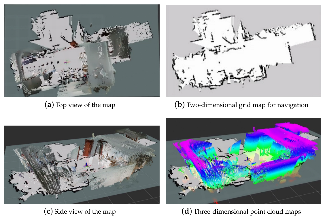
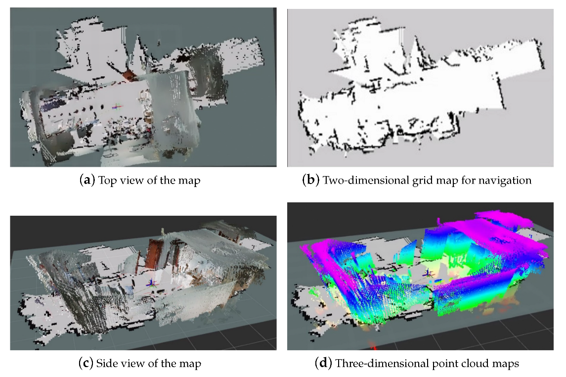
  • When the laser and visual information are tracked normally, the fusion algorithm can be used to improve the accuracy of mapping.
  • When visual tracking fails, the localization from laser SLAM can be used to obtain continuous results.
  • The two-dimensional laser can compensate for the limited field of view of the depth camera, which enhances the navigation safety.

5. Human–Machine Interaction

For mobile robots, apart from environment perception, interaction with humans is also essential. Human–machine interaction helps robots understand human intentions, enabling them to make informed decisions. Here, 13 gesture recognitions are studied as an interaction method.

5.1. Improved YOLOv5 by Adding ASFF

The original YOLOv5 network is shown in Figure 10. The original YOLOv5 consists of three parts, backbone, neck, and head. Among them, PANet performs feature fusion in the network. However, in PANet, simple addition is used for feature fusion, which does not fully utilize the feature information of different scales. Therefore, the improved YOLOv5 with ASFF can incorporate information from different scales to improve the accuracy of detecting objects of different scales.
Figure 11 and Figure 12 illustrate the process of feature fusion using ASFF. In this process, features X 1 , X 2 , and X 3 from level 1, level 2, and level 3, respectively, are multiplied by weight parameters α , β , and γ to obtain weighted features. These weighted features are then summed up to obtain the fused feature ASFF, as shown in Equation (8) [39],
y i j l = α i j l · x i j 1 l + β i j l · x i j 2 l + γ i j l · x i j 3 l
where y i j l implies the ( i , j ) -th vector of the output feature maps y l among channels. α i j l , β i j l , and γ i j l refer to the spatial importance weights for the feature maps at three different levels to level l, which are adaptively learned by the network [39].
The weight parameters α , β , and γ are calculated by applying 1 × 1 convolution to the feature maps of level 1 to level 3 after resizing. These parameters are then stacked, ensuring that their values range from 0 to 1 and their sum is 1, as shown in Equation (9) [39],
α i j l = e γ α i j l e γ α i j l + e γ β i j l + e γ γ i j l
where α i j l , β i j l , and γ i j l are defined by using the softmax function with γ α i j l , γ β i j l , and γ γ i j l as control parameters, respectively. We use 1 × 1 convolution layers to compute the weight scalar maps γ α l , γ β l and γ γ l from x 1 l , x 2 l and x 3 l , respectively, and they can thus be learned through standard back-propagation [39].

5.2. Training Result

The confusion matrix diagrams of YOLOv5 and the improved YOLOv5 with ASFF are shown in Figure 13a,b. It can be observed that the probabilities of correctly identifying the human hand and the pedestrian are 0.82 and 0.86, respectively, which is consistent with the values of 0.82 and 0.85 obtained by YOLOv5. The probability of incorrectly identifying the pedestrian is 0.45, slightly lower than the 0.46 obtained by YOLOv5. The probability of failing to identify the pedestrian is 0.13, which is lower than the 0.15 obtained by YOLOv5. Based on the confusion matrix, the improved network performs slightly better than the original network, but the improvement is limited.
As depicted in Figure 14a,b, the curves represent the training results. The Box curve represents the mean loss function, where a smaller value indicates more accurate prediction box positioning. Objectness represents the mean loss of object detection, and a smaller value indicates more accurate object detection. Classification represents the mean loss of classification, where a smaller value indicates more accurate classification. This can be expressed as Equation (10). The Precision curve represents precision, where a higher value indicates higher accuracy.
P r e c i s i o n = T P T P + F P
where T P represents the number of predicting positive classes as positive classes, and F P represents the number of predicting negative classes as positive classes.
The calculation formula for recall is shown in Equation (11). A higher value of recall indicates higher accuracy.
R e c a l l = T P T P + F N
where T P is the number of predicting positive classes as positive classes, F N is the number of predicting positive classes as negative classes. m A P indicates the area enclosed by the two axes of accuracy and recall. The higher the value, the more accurate the detection.
F 1 is another indicator of classification. The calculation formula of F 1 is shown as Equation (12).
F 1 = 2 × r e c a l l × p r e c i s i o n r e c a l l + p r e c i s i o n
As depicted in Figure 14a,b, the mean loss function of the improved YOLOv5 is approximately 0.15, which is significantly lower than the 0.03 of YOLOv5. The classification loss is around 0.0010, slightly lower than the 0.0015 of YOLOv5. The highest accuracy reaches approximately 0.9, slightly higher than the nearly 0.9 of YOLO v5. The recall rate is approximately 0.83, higher than the 0.8 of YOLO v5. The m A P is nearly 0.9, which is significantly higher than the around 0.85 of YOLO v5. Overall, the improved network with ASFF outperforms the original network.

5.3. Test Result

It can be observed from the above experiments that the improved YOLOv5 network achieves better recognition accuracy. Therefore, the improved YOLOv5 network is utilized to enable the recognition of additional gestures in the quadruped robot, facilitating the basic understanding and judgment of pedestrians by the quadruped robot. As depicted in Figure 15, the experiment successfully realizes the recognition of 13 gestures. Figure 14a illustrates the gesture recognition experiment, where the quadruped robot adjusts its elevation angle to approximately 30 , and the camera detects the gestures. Figure 15b presents the detection results of gesture recognition. Notably, gestures “4” and “5” are prone to confusion. To address this issue, a larger dataset, image preprocessing methods, and network improvements are required.

6. Challenge of Environment Perception System for Legged Robots

To further investigate the differences in environment perception performance between wheeled and legged robots, a comparative experimental platform was set up using a vehicle equipped with LiDAR and vision sensors. The same hardware and software configurations were employed to highlight the challenges faced by the environment perception system of legged robots.
The fusion results obtained from the vehicle are presented in Figure 16. Figure 16a depicts the top view of the map, Figure 16b shows the two-dimensional grid map for navigation, Figure 16c displays the side view of the map, and Figure 16d exhibits the three-dimensional point cloud maps. Comparing these results with the multi-sensor fusion SLAM results obtained from the quadruped robot, it can be observed that the map boundaries in the vehicle’s mapping results are clearer. This indicates that the SLAM mapping resolution on the vehicle is higher compared to that on the quadruped robot.
The factors that weaken the environment perception performance of legged robots may include:
  • Oscillating body.
  • Changing attitude.
  • Non-smooth speed.
To reduce the influence of the above three factors, maybe IMU or other sensors for positioning should be considered into multi-sensor fusion SLAM.

7. Conclusions

In this paper, the environment perception system of quadruped robots based on LIDAR and vision is investigated by comparative platforms, sensors, and algorithms.
In the SLAM part, initial experiments are conducted on quadruped robots using a single laser and visual sensor for map construction. However, these experiments reveal the limitations of a single sensor, including the lack of visual information and incomplete map construction. To address these issues and achieve more accurate and robust localization results, we employ the Extended Kalman Filter method to fuse data from the LiDAR and depth camera. The fusion approach effectively compensates for the missing visual information in the laser map and addresses the limited field of view angle. Moreover, when one sensor fails, the other sensor ensures uninterrupted positioning.
In the visual recognition part, we establish a human–machine interaction system and enhance gesture recognition using the added ASFF improved YOLOv5 network. Experimental results demonstrate a significant improvement in gesture recognition accuracy with the improved YOLOv5 network.
In addition, the difference of environmental perception performance between wheeled and legged robots is studied. Additionally, the results shows the environmental perception performance of the quadruped robot is weaker than that of the vehicle, since the vehicle is more stable in the movement.
With the rapid advancements in artificial intelligence and computer vision, quadruped robots are poised to find extensive applications in various fields such as surveying, search and rescue operations, courier services during epidemics, and assistance for the disabled as guide dogs. Furthermore, the environmental perception system developed in this study can be applied not only to quadruped robots but also to autonomous driving, offering promising prospects for broad applications.
However, the mapping results of the quadruped robot in this study still suffer from noise and blurred boundaries due to unstable motion. To address these issues, the following methods can be employed:
  • Involve IMU or other sensors for positioning into multi-sensor fusion SLAM.
  • Reduce the walking speed of the quadruped robot during map construction and implement intermittent stops to mitigate motion instability.
  • Enhance the stability of the robot’s motion by improving gait planning methods and reducing shaking during movement. Additionally, incorporating cushioning materials at the foot end can help minimize ground impact while walking.
  • Utilize mechanical anti-shake techniques and specialized sensors, such as gyroscopes and accelerometers, to detect robot movement and compensate for camera motion.
  • Introduce filtering algorithms in the mapping algorithm to remove image noise.
  • Apply digital video stabilization methods to estimate and smooth motion, filter out unwanted motion, and reconstruct stable video.

Author Contributions

Conceptualization, G.C. and L.H.; methodology, G.C. and L.H.; software, G.C. and L.H.; validation, G.C. and L.H.; formal analysis, G.C. and L.H.; investigation, G.C. and L.H.; resources, G.C. and L.H.; data curation, G.C. and L.H.; writing—original draft preparation, G.C. and L.H.; writing—review and editing, G.C. and L.H.; visualization, G.C. and L.H.; supervision, G.C.; project administration, G.C.; funding acquisition, G.C. All authors have read and agreed to the published version of the manuscript.

Funding

This work was supported by National Natural Science Foundation of China (62103036), Fundamental Research Funds for the Central Universities (2022JBMC025), National Key Research and Development Program of China (2022YFB4701600), and Joint Fund of the Ministry of Education for Equipment Pre-research (8091B032147).

Data Availability Statement

Not applicable.

Conflicts of Interest

The authors declare no conflict of interest.

References

  1. Chen, G.; Wei, N.; Yan, L.; Lu, H.; Li, J. Perturbation-based approximate analytic solutions to an articulated SLIP model for legged robots. Commun. Nonlinear Sci. Numer. Simul. 2023, 117, 106943. [Google Scholar] [CrossRef]
  2. Hui, Z. Research on Environmental Perception, Recognition and Leader Following Algorithm of the Quadruped Robot. Ph.D. Thesis, Shandong University, Jinan, China, 2016. [Google Scholar]
  3. Chen, G.; Wang, J.; Wang, S.; Zhao, J.; Shen, W. Compliance control for a hydraulic bouncing system. ISA Trans. 2018, 79, 232–238. [Google Scholar] [CrossRef] [PubMed]
  4. Chen, G.; Wei, N.; Lu, H.; Yan, L.; Li, J. Optimization and evaluation of swing leg retraction for a hydraulic biped robot. J. Field Robot. 2023. early view. [Google Scholar] [CrossRef]
  5. Chen, G.; Guo, S.; Hou, B.; Wang, J. Virtual model control for quadruped robots. IEEE Access 2020, 8, 140736–140751. [Google Scholar] [CrossRef]
  6. Gao, Y.; Wang, D.; Wei, W.; Yu, Q.; Liu, X.; Wei, Y. Constrained Predictive Tracking Control for Unmanned Hexapod Robot with Tripod Gait. Drones 2022, 6, 246. [Google Scholar] [CrossRef]
  7. Lee, J.W.; Lee, W.; Kim, K.D. An algorithm for local dynamic map generation for safe UAV navigation. Drones 2021, 5, 88. [Google Scholar] [CrossRef]
  8. Lee, D.K.; Nedelkov, F.; Akos, D.M. Assessment of Android Network Positioning as an Alternative Source of Navigation for Drone Operations. Drones 2022, 6, 35. [Google Scholar] [CrossRef]
  9. Xia, X.; Hashemi, E.; Xiong, L.; Khajepour, A. Autonomous Vehicle Kinematics and Dynamics Synthesis for Sideslip Angle Estimation Based on Consensus Kalman Filter. IEEE Trans. Control Syst. Technol. 2022, 31, 179–192. [Google Scholar] [CrossRef]
  10. Gao, L.; Xiong, L.; Xia, X.; Lu, Y.; Yu, Z.; Khajepour, A. Improved vehicle localization using on-board sensors and vehicle lateral velocity. IEEE Sens. J. 2022, 22, 6818–6831. [Google Scholar] [CrossRef]
  11. Ramachandran, A.; Sangaiah, A.K. A review on object detection in unmanned aerial vehicle surveillance. Int. J. Cogn. Comput. Eng. 2021, 2, 215–228. [Google Scholar] [CrossRef]
  12. Liang, Y.; Li, M.; Jiang, C.; Liu, G. CEModule: A computation efficient module for lightweight convolutional neural networks. IEEE Trans. Neural Netw. Learn. Syst. 2021. early access. [Google Scholar] [CrossRef]
  13. Zhou, P.; Liu, G.; Wang, J.; Weng, Q.; Zhang, K.; Zhou, Z. Lightweight unmanned aerial vehicle video object detection based on spatial-temporal correlation. Int. J. Commun. Syst. 2022, 35, e5334. [Google Scholar] [CrossRef]
  14. Ocando, M.G.; Certad, N.; Alvarado, S.; Terrones, Á. Autonomous 2D SLAM and 3D mapping of an environment using a single 2D LIDAR and ROS. In Proceedings of the 2017 Latin American Robotics Symposium (LARS) and 2017 Brazilian Symposium on Robotics (SBR), Curitiba, Brazil, 8–11 November 2017; pp. 1–6. [Google Scholar]
  15. Jeong, W.; Lee, K.M. CV-SLAM: A new ceiling vision-based SLAM technique. In Proceedings of the 2005 IEEE/RSJ International Conference on Intelligent Robots and Systems, Edmonton, AB, Canada, 2–6 August 2005; pp. 3195–3200. [Google Scholar]
  16. Davison, A.J.; Reid, I.D.; Molton, N.D.; Stasse, O. MonoSLAM: Real-time single camera SLAM. IEEE Trans. Pattern Anal. Mach. Intell. 2007, 29, 1052–1067. [Google Scholar] [CrossRef] [PubMed]
  17. Belter, D.; Nowicki, M.; Skrzypczyński, P. Evaluating map-based RGB-D SLAM on an autonomous walking robot. In International Conference on Automation, 2–4 March 2016, Warsaw, Poland; Springer: Cham, Switzerland, 2016; pp. 469–481. [Google Scholar]
  18. Callmer, J.; Törnqvist, D.; Gustafsson, F.; Svensson, H.; Carlbom, P. Radar SLAM using visual features. EURASIP J. Adv. Signal Process. 2011, 2011, 71. [Google Scholar] [CrossRef]
  19. Mittal, A.; Shivakumara, P.; Pal, U.; Lu, T.; Blumenstein, M. A new method for detection and prediction of occluded text in natural scene images. Signal Process. Image Commun. 2022, 100, 116512. [Google Scholar] [CrossRef]
  20. Schlosser, J.; Chow, C.K.; Kira, Z. Fusing lidar and images for pedestrian detection using convolutional neural networks. In Proceedings of the 2016 IEEE International Conference on Robotics and Automation (ICRA), Stockholm, Sweden, 16–21 May 2016; pp. 2198–2205. [Google Scholar]
  21. Dhouioui, M.; Frikha, T. Design and implementation of a radar and camera-based obstacle classification system using machine-learning techniques. J. Real-Time Image Process. 2021, 18, 2403–2415. [Google Scholar] [CrossRef]
  22. López, E.; Barea, R.; Gómez, A.; Saltos, Á.; Bergasa, L.M.; Molinos, E.J.; Nemra, A. Indoor SLAM for micro aerial vehicles using visual and laser sensor fusion. In Robot 2015: Second Iberian Robotics Conference; Springer: Cham, Switzerland, 2016; pp. 531–542. [Google Scholar]
  23. Li, J.; Zhang, X.; Li, J.; Liu, Y.; Wang, J. Building and optimization of 3D semantic map based on Lidar and camera fusion. Neurocomputing 2020, 409, 394–407. [Google Scholar] [CrossRef]
  24. Jin, D. Research on Laser Vision Fusion SLAM and Navigation for Mobile Robots in Complex Indoor Environments. Ph.D. Thesis, Harbin Institute of Technology, Harbin, China, 2020. [Google Scholar]
  25. Valente, M.; Joly, C.; de La Fortelle, A. Deep sensor fusion for real-time odometry estimation. In Proceedings of the 2019 IEEE/RSJ International Conference on Intelligent Robots and Systems (IROS), Macau, China, 3–8 November 2019; pp. 6679–6685. [Google Scholar]
  26. Alatise, M.B.; Hancke, G.P. Pose estimation of a mobile robot based on fusion of IMU data and vision data using an extended Kalman filter. Sensors 2017, 17, 2164. [Google Scholar] [CrossRef] [PubMed]
  27. Xia, X.; Meng, Z.; Han, X.; Li, H.; Tsukiji, T.; Xu, R.; Zheng, Z.; Ma, J. An automated driving systems data acquisition and analytics platform. Transp. Res. Part C Emerg. Technol. 2023, 151, 104120. [Google Scholar] [CrossRef]
  28. Liu, W.; Xia, X.; Xiong, L.; Lu, Y.; Gao, L.; Yu, Z. Automated vehicle sideslip angle estimation considering signal measurement characteristic. IEEE Sens. J. 2021, 21, 21675–21687. [Google Scholar] [CrossRef]
  29. Xia, X.; Xiong, L.; Huang, Y.; Lu, Y.; Gao, L.; Xu, N.; Yu, Z. Estimation on IMU yaw misalignment by fusing information of automotive onboard sensors. Mech. Syst. Signal Process. 2022, 162, 107993. [Google Scholar] [CrossRef]
  30. Wang, K.; Liu, M.; Ye, Z. An advanced YOLOv3 method for small-scale road object detection. Appl. Soft Comput. 2021, 112, 107846. [Google Scholar] [CrossRef]
  31. Qiu, M.; Huang, L.; Tang, B.H. ASFF-YOLOv5: Multielement detection method for road traffic in UAV images based on multiscale feature fusion. Remote Sens. 2022, 14, 3498. [Google Scholar] [CrossRef]
  32. Zhu, X.; Lyu, S.; Wang, X.; Zhao, Q. TPH-YOLOv5: Improved YOLOv5 based on transformer prediction head for object detection on drone-captured scenarios. In Proceedings of the IEEE/CVF International Conference on Computer Vision, Montreal, BC, Canada, 11–17 October 2021; pp. 2778–2788. [Google Scholar]
  33. Liu, W.; Quijano, K.; Crawford, M.M. YOLOv5-Tassel: Detecting tassels in RGB UAV imagery with improved YOLOv5 based on transfer learning. IEEE J. Sel. Top. Appl. Earth Obs. Remote Sens. 2022, 15, 8085–8094. [Google Scholar] [CrossRef]
  34. Norzam, W.; Hawari, H.; Kamarudin, K. Analysis of mobile robot indoor mapping using GMapping based SLAM with different parameter. In IOP Conference Series: Materials Science and Engineering; IOP Publishing: Bristol, UK, 2019; Volume 705, p. 012037. [Google Scholar]
  35. Mur-Artal, R.; Tardós, J.D. Orb-slam2: An open-source slam system for monocular, stereo, and rgb-d cameras. IEEE Trans. Robot. 2017, 33, 1255–1262. [Google Scholar] [CrossRef]
  36. Labbé, M.; Michaud, F. RTAB-Map as an open-source lidar and visual simultaneous localization and mapping library for large-scale and long-term online operation. J. Field Robot. 2019, 36, 416–446. [Google Scholar] [CrossRef]
  37. Xiao, Y. Research on Real-Time Positioning and Mapping of Robots Based on Laser Vision Fusion. Master’s Thesis, University of Chinese Academy of Sciences (Shenzhen Institute of Advanced Technology, Chinese Academy of Sciences), Shenzhen, China, 2018. [Google Scholar]
  38. Moore, T.; Stouch, D. A generalized extended kalman filter implementation for the robot operating system. In Intelligent Autonomous Systems 13; Springer: Cham, Switzerland, 2016; pp. 335–348. [Google Scholar]
  39. Liu, S.; Huang, D.; Wang, Y. Learning spatial fusion for single-shot object detection. arXiv 2019, arXiv:1911.09516. [Google Scholar]
Figure 1. (a,b) The comparative experimental platforms with LiDAR and depth-camera.
Drones 07 00329 g001
Figure 2. Software architecture.
Drones 07 00329 g002
Figure 3. Mapping process of the quadruped robot with LiDAR.
Drones 07 00329 g003
Figure 4. Mapping result of the quadruped robot with LiDAR.
Drones 07 00329 g004
Figure 5. The successful tracking outcome achieved with ORB-SLAM2: feature points is labeled and point cloud map can be generated.
Drones 07 00329 g005
Figure 6. The resulting point cloud map achieved with ORB-SLAM2.
Drones 07 00329 g006
Figure 7. The failed tracking outcome achieved with ORB-SLAM2: No feature points are labeled and a point cloud map can not be generated.
Drones 07 00329 g007
Figure 8. The experiment result using RTAB-MAP on the quadruped robot. (a) Top view of the map; (b) Two-dimensional grid map for navigation; (c) Three-dimensional point cloud maps.
Drones 07 00329 g008
Figure 9. The results of multi-sensor fusion SLAM on the quadruped robot.
Drones 07 00329 g009
Figure 10. The original YOLOv5 network.
Drones 07 00329 g010
Figure 11. Illustration of the ASFF mechanism. For each level, the features of all the other levels are resized to the same shape and spatially fused according to the learned weight maps [39].
Drones 07 00329 g011
Figure 12. The simplified ASFF principle.
Drones 07 00329 g012
Figure 13. Confusion matrix of different gesture recognition.
Drones 07 00329 g013
Figure 14. Training results of different gesture recognition.
Drones 07 00329 g014
Figure 15. Test results of different gesture recognition.
Drones 07 00329 g015
Figure 16. The results of multi-sensor fusion SLAM on the vehicle.
Drones 07 00329 g016
Table 1. The comparative experimental platforms: quadruped robot and vehicle.
PlatformQuadruped Robot (Unitree Go1)Vehicle (Nano Pro)
LiDAR3i LiDAR Delta2A
VisionKinect V2Astra Pro
ControllerJetson Nano
AlgorithmBoth platforms use the same algorithm
Disclaimer/Publisher’s Note: The statements, opinions and data contained in all publications are solely those of the individual author(s) and contributor(s) and not of MDPI and/or the editor(s). MDPI and/or the editor(s) disclaim responsibility for any injury to people or property resulting from any ideas, methods, instructions or products referred to in the content.

