
Resource Scheduling for UAV-Assisted Failure-Prone MEC in Industrial Internet

Abstract
:1. Introduction
- (1)
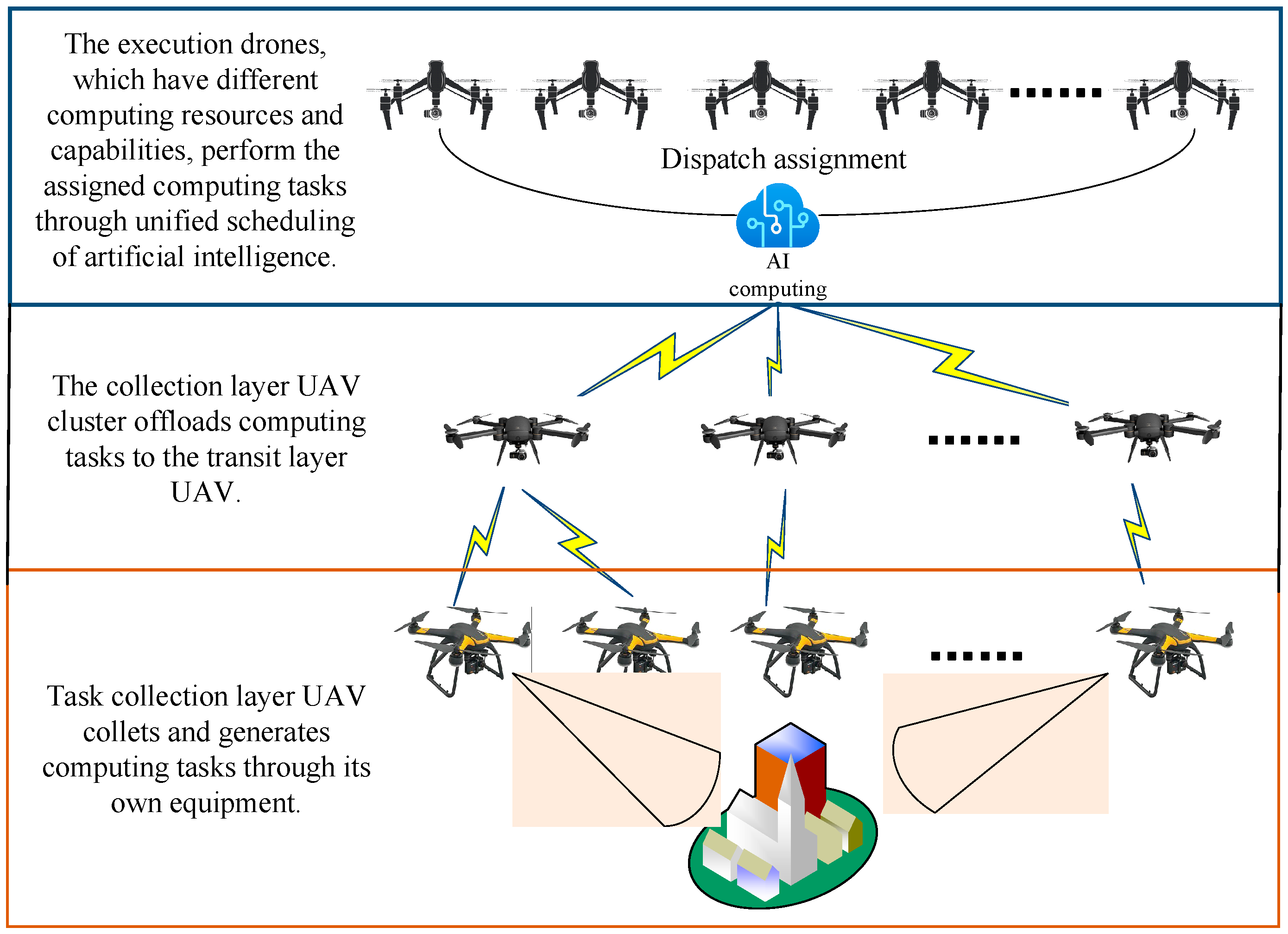
- In this paper, we study the problem of MEC-IIN scenario from a new perspective. According to the characteristics of the IIN scenario, dynamic UAVs are introduced as edge arithmetic to assist resource-limited IIN end devices to perform computational tasks.
- (2)
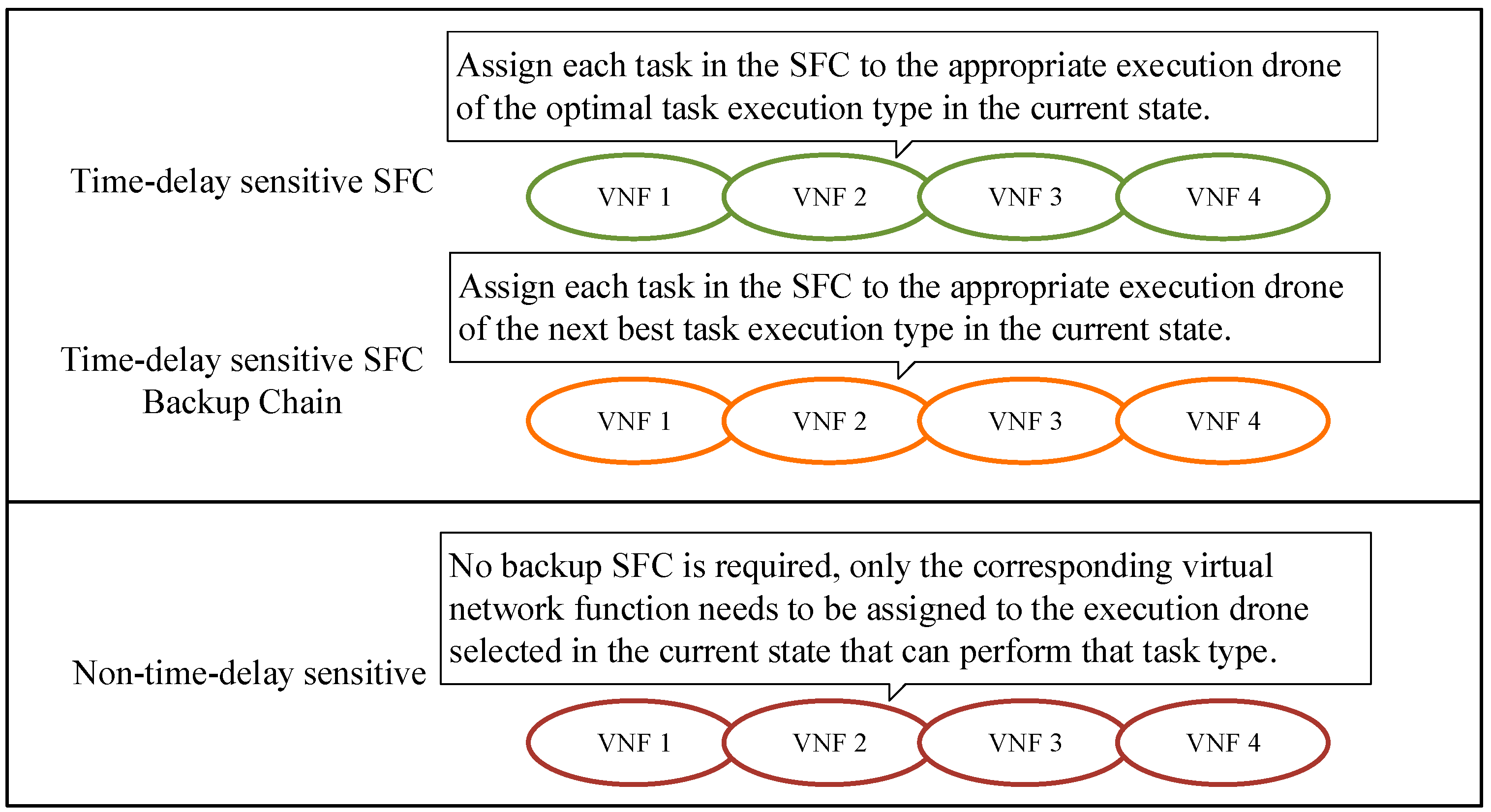
- For latency-sensitive tasks, the dynamic crash probability of MEC server is introduced, and the backup synchronous execution is used to increase the reliability. By jointly optimizing task execution device selection and computing resource allocation, an effective strategy to reduce system latency under this model is investigated.
- (3)
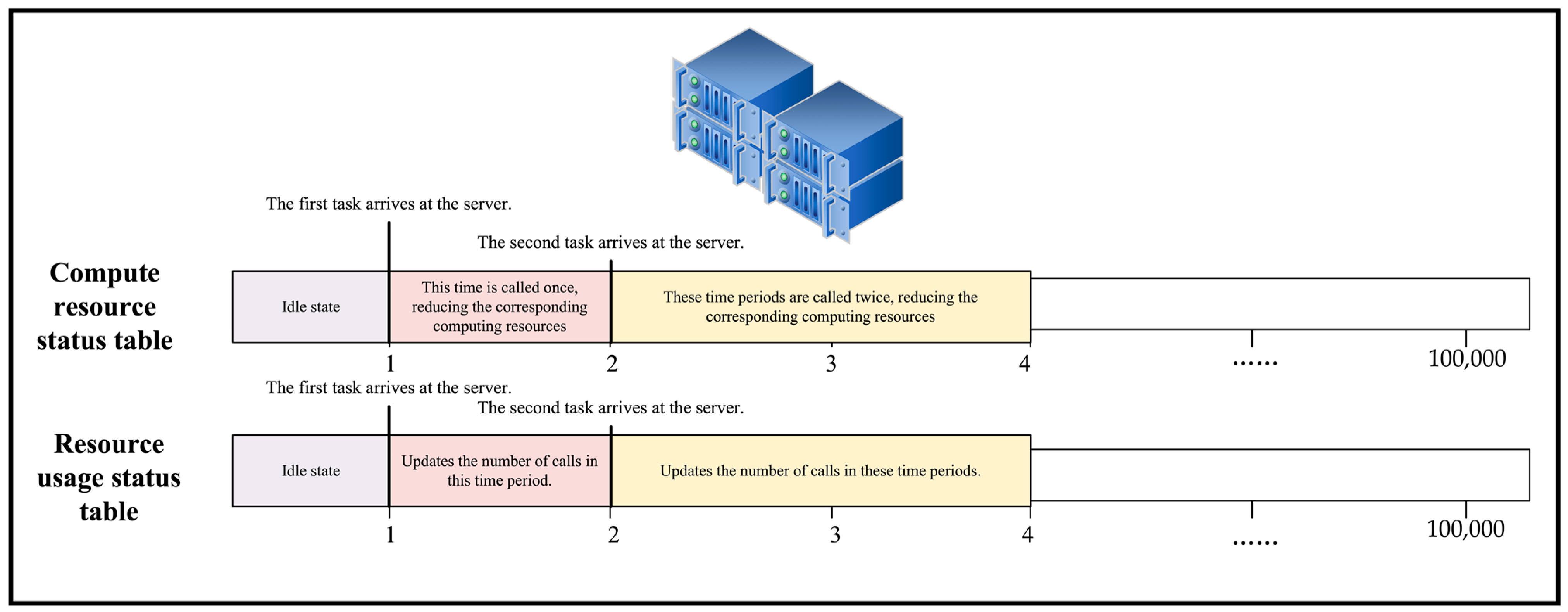
- In this paper, a real-time equipment status update system is constructed to make the equipment working status data in the system real-time and accurate. The introduction of this system makes the dynamic update of crash probability coefficients more accurate and provides more real-time valid information to assist decision making for the dynamic deployment of VNFs by algorithms.
- (4)
- To capture and handle the time-varying failure probabilities of VNFs, the long-term resource provisioning problem is discretized into a series of single-slot optimization problems, which are shown to be NP-hard.
2. Materials and Methods
2.1. System Model
2.1.1. Network Model
2.1.2. Crash Probability Model
2.1.3. Backup Parallel Execution Model
2.1.4. Communication Model
2.1.5. Computational Model
2.2. Problem Description
2.3. Dynamic Task Scheduling Location Optimization Algorithm
2.3.1. Markov Decision Process
- (1)
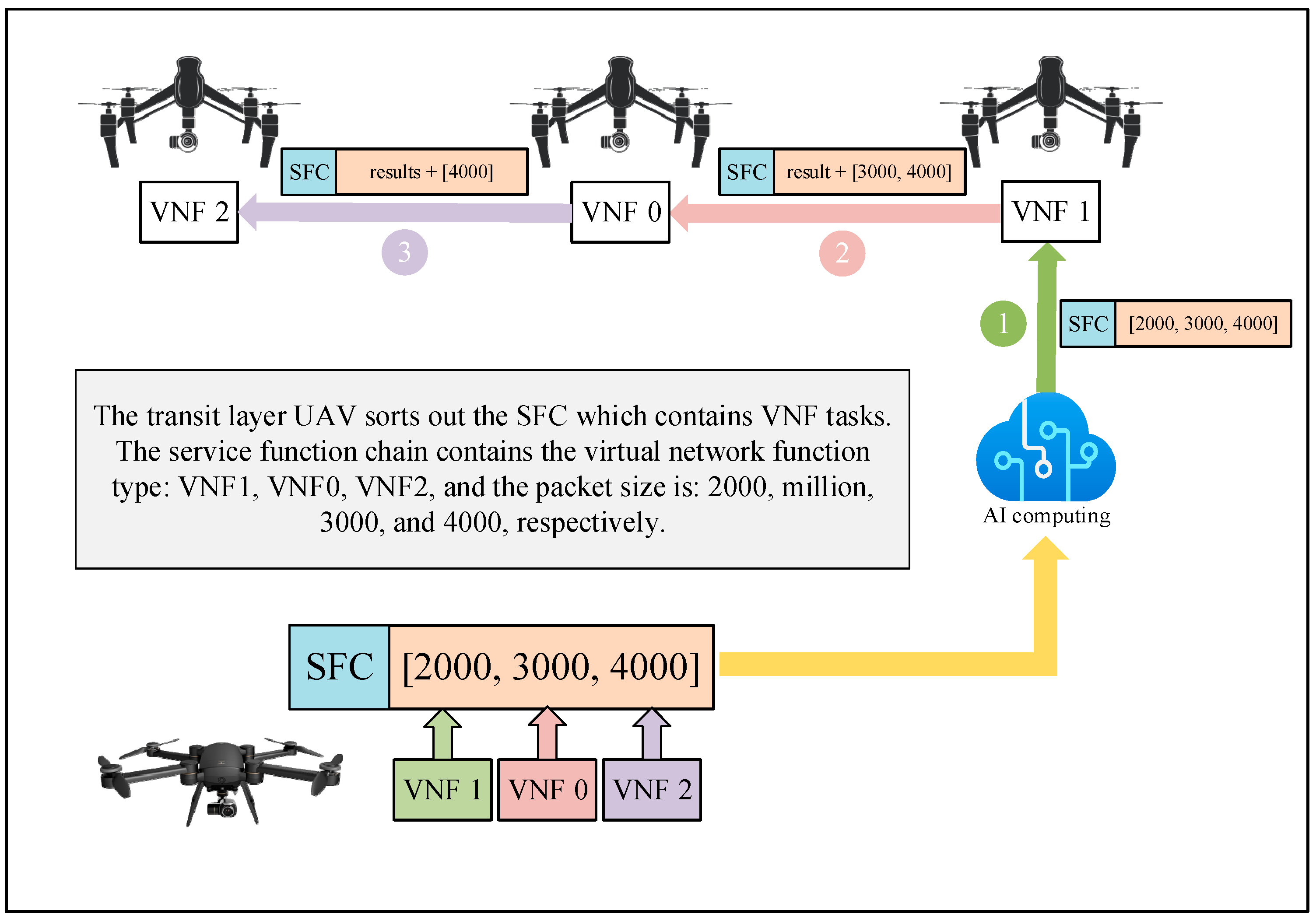
- State Space: The state of the system contains three layers of the UAVs state and task execution, namely: the location of each collection layer UAV and information about the computational tasks it generates; the location of each transmission layer UAV and information about SFC tasks after collating data; the location of each execution layer UAV, the contained VNF and resource usage information; and the current execution state of all tasks generated within the system. Among them, the locations of the UAVs are represented by a three-dimensional Cartesian coordinate system, and each generated task contains task generation time, task type, task data size, and task delay-sensitive composition.
- (2)
- Action Space: The action a of the system contains both the execution layer UAVs assigned for each task and the allocated computational resources. The task execution positions of the n tasks generated by the n collection layer UAVs can be denoted as , and the allocation of computational resources is denoted by f = [f1, f2, …, fN]. Thus, the action a is the combination of the elements in and f.
- (3)
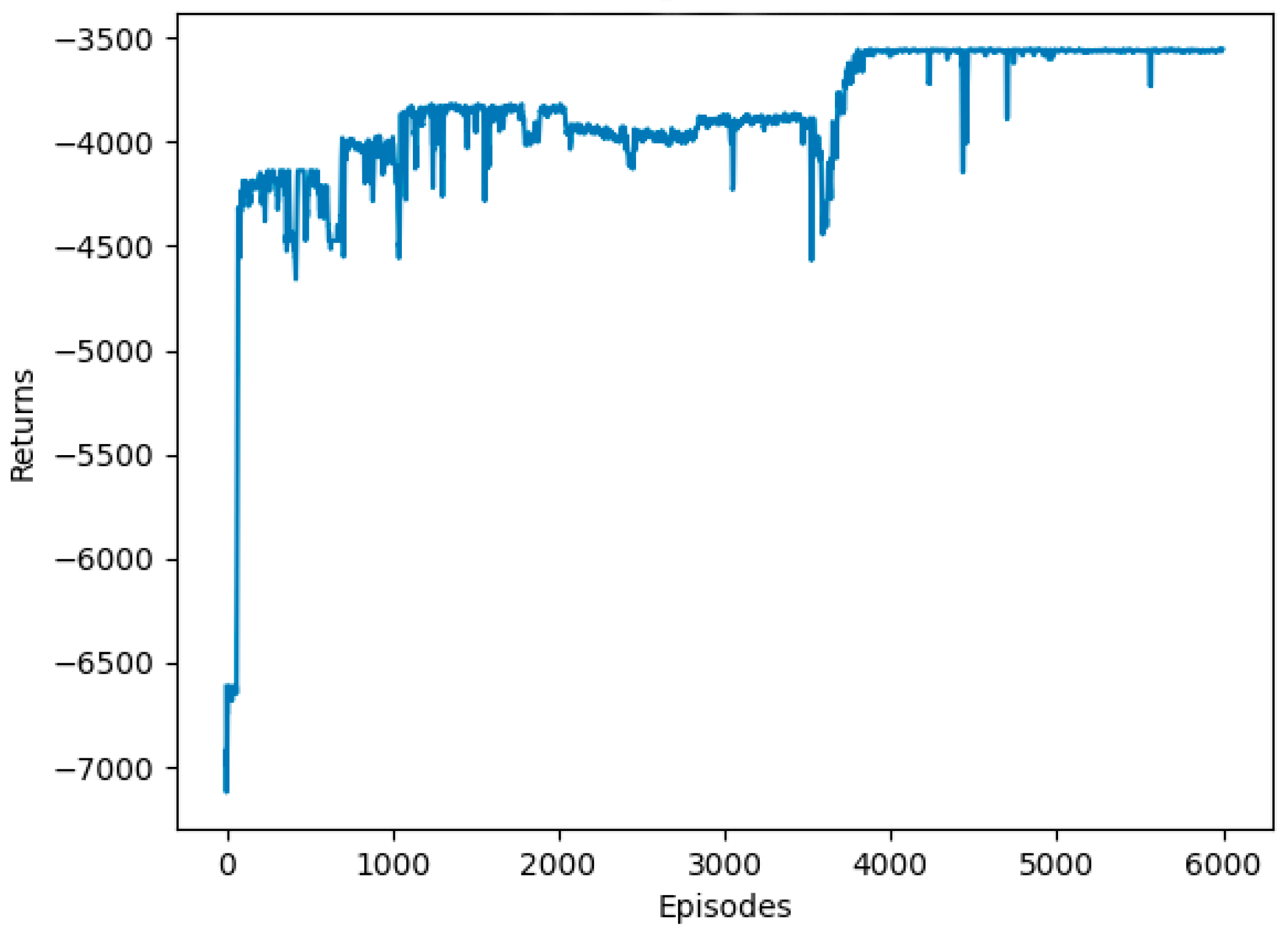
- Reward Functions: For each step, after executing each action a, the intelligence will calculate the reward obtained according to the reward and punishment function R. The goal of the optimization problem in this paper is to obtain the minimum total system execution delay, while DRL pursues the actions that obtain the maximum reward sum. Therefore, in this paper, the delay derived from the i-th step operation is taken as its opposite, −, as the reward for the i-th step action, i.e., = −, so that the DRL algorithm tends to the direction of the reduction of the total system execution delay.
2.3.2. Experience Storage
2.3.3. Q-Learning Algorithm
| Algorithm 1: Q-learning algorithm |
| 1: Initialize Q form |
| 2: for episode 1→E do: |
| 3: Initialize the state of UAVs at each execution level |
| 4: Get the initial state of the environment s |
| 5: for episode 1→T do: |
| 6: Use the epsilon-greedy strategy to select the action a in the current state s based on Q-value |
| 7: Execute action a; get environment feedback of |
| 8: |
| 9: |
| 10: end for |
| 11: end for |
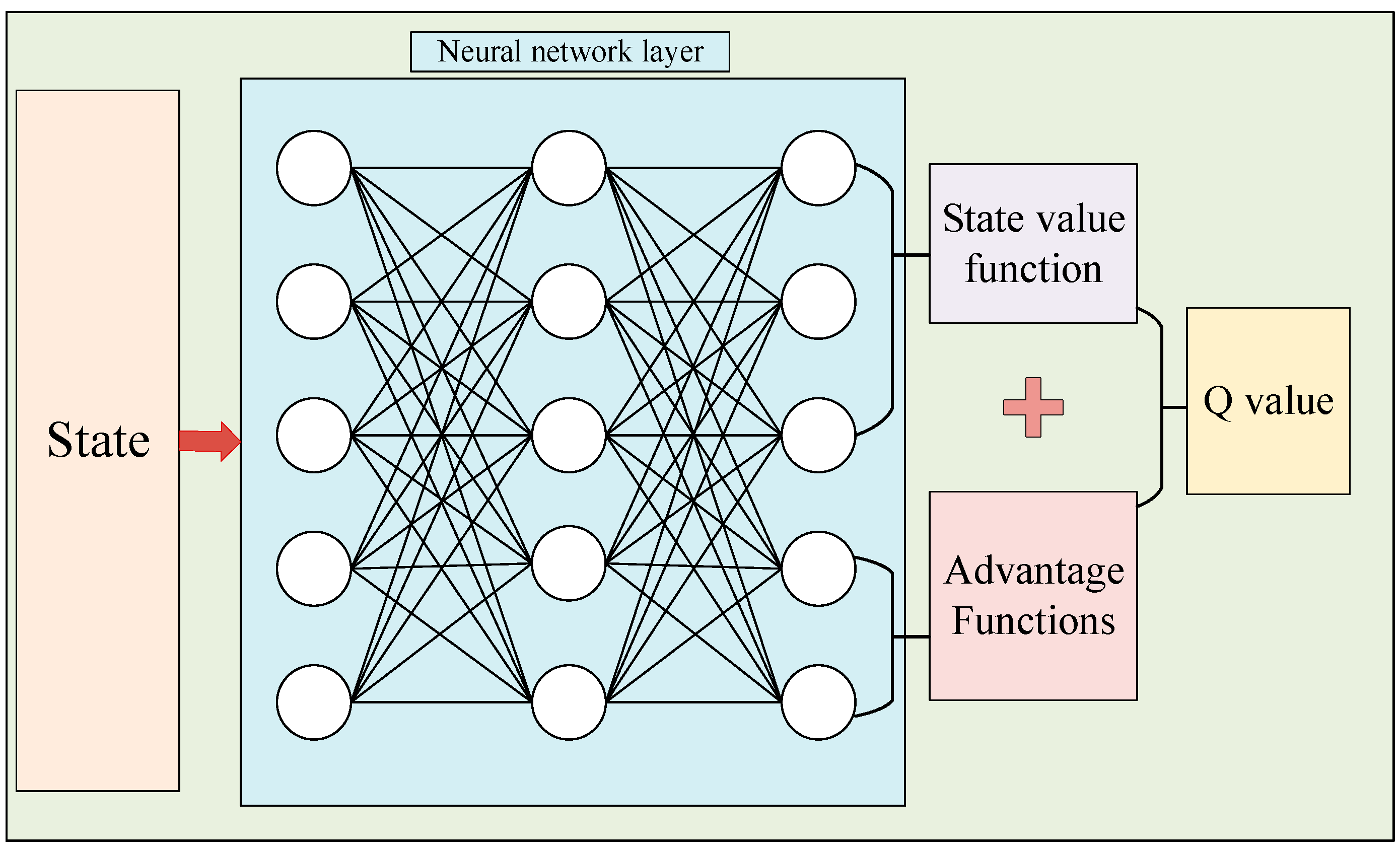
2.3.4. DTSOA Algorithm
| Algorithm 2: DTSOA algorithm |
| 1: Initialize neural network Q(s, a) parameters with random parameters |
| 2: Initialize experience replay pool M |
| 3:for episode 1→E do: |
| 4: Initialize the state of UAVs at each execution level |
| 5: Get the initial state of the environment s1 |
| 6: Initialization done = False |
| 7: while not done: |
| 8: Select action a1 according to the current network Q(s, a) with epsilon-greedy. strategy |
| 9: Execute action a1; get return r1; determine whether to enter the stop state, if yes, d1 = True, else d1 = False; and enter the new state s2 |
| 10: Store (s1, a1, r1, d1, s2) into the experience replay pool M |
| 11: if the data in M is enough then sampling n data from the {(si, ai, ri, di, si+1)}i=1, ……, n |
| 12: Put the data batch into the output dominance function and state value function through the neural network, and calculate the Q-value. |
| 13: Minimize target loss as a way to update the current network |
| 14: Update the target network |
| 15: end for |
| 16: end for |
2.3.5. Algorithm Complexity Analysis
3. Results and Discussion
4. Conclusions
Author Contributions
Funding
Institutional Review Board Statement
Informed Consent Statement
Data Availability Statement
Conflicts of Interest
References
- Zhou, Y.; Yu, F.R.; Chen, J.; Kuo, Y. Resource Allocation for Information-Centric Virtualized Heterogeneous Networks with In-Network Caching and Mobile Edge Computing. IEEE Trans. Veh. Technol. 2017, 66, 11339–11351. [Google Scholar] [CrossRef]
- Pham, C.; Tran, N.H.; Ren, S.; Saad, W.; Hong, C.S. Traffic-Aware and Energy-Efficient VNF Placement for Service Chaining: Joint Sampling and Matching Approach. IEEE Trans. Serv. Comput. 2020, 13, 172–185. [Google Scholar] [CrossRef]
- Fu, X.; Yu, F.R.; Wang, J.; Qi, Q.; Liao, J. Service Function Chain Embedding for NFV-Enabled IoT Based on Deep Reinforcement Learning. IEEE Commun. Mag. 2019, 57, 102–108. [Google Scholar] [CrossRef]
- Pei, J.; Hong, P.; Pan, M.; Liu, J.; Zhou, J. Optimal VNF Placement via Deep Reinforcement Learning in SDN/NFV-Enabled Networks. IEEE J. Sel. Areas Commun. 2020, 38, 263–278. [Google Scholar] [CrossRef]
- Suzuki, A.; Kobayashi, M.; Takahashi, Y.; Harada, S.; Ishibashi, K.; Kawahara, R. Extendable NFV-Integrated Control Method Using Reinforcement Learning. In Proceedings of the 2018 IEEE International Conference on Communications (ICC), Kansas City, MO, USA, 20–24 May 2018; pp. 1–7. [Google Scholar]
- Sun, J.; Liu, F.; Wang, H.; Ahmed, M.; Li, Y.; Zhang, L.; Zeng, H. Network Function Placement Under Randomly Arrived Networking Traffic. IEEE Trans. Cogn. Commun. Netw. 2021, 7, 1382–1398. [Google Scholar] [CrossRef]
- Pham, T.-M.; Fdida, S.; Nguyen, T.-T.-L.; Chu, H.-N. Modeling and Analysis of Robust Service Composition for Network Functions Virtualization. Comput. Netw. 2020, 166, 106989. [Google Scholar] [CrossRef]
- Wang, M.; Cheng, B.; Chen, J. Joint Availability Guarantee and Resource Optimization of Virtual Network Function Placement in Data Center Networks. IEEE Trans. Netw. Serv. Manag. 2020, 17, 821–834. [Google Scholar] [CrossRef]
- Chen, Y.; Wu, J. Latency-Efficient VNF Deployment and Path Routing for Reliable Service Chain. IEEE Trans. Netw. Sci. Eng. 2021, 8, 651–661. [Google Scholar] [CrossRef]
- Kang, R.; He, F.; Oki, E. Virtual Network Function Allocation in Service Function Chains Using Backups with Availability Schedule. IEEE Trans. Netw. Serv. Manag. 2021, 18, 4294–4310. [Google Scholar] [CrossRef]
- Fan, J.; Jiang, M.; Rottenstreich, O.; Zhao, Y.; Guan, T.; Ramesh, R.; Das, S.; Qiao, C. A Framework for Provisioning Availability of NFV in Data Center Networks. IEEE J. Sel. Areas Commun. 2018, 36, 2246–2259. [Google Scholar] [CrossRef]
- Li, J.; Liang, W.; Huang, M.; Jia, X. Reliability-Aware Network Service Provisioning in Mobile Edge-Cloud Networks. IEEE Trans. Parallel Distrib. Syst. 2020, 31, 1545–1558. [Google Scholar] [CrossRef]
- Yang, S.; Li, F.; Yahyapour, R.; Fu, X. Delay-Sensitive and Availability-Aware Virtual Network Function Scheduling for NFV. IEEE Trans. Serv. Comput. 2022, 15, 188–201. [Google Scholar] [CrossRef]
- Qiu, Y.; Liang, J.; Leung, V.C.M.; Wu, X.; Deng, X. Online Reliability-Enhanced Virtual Network Services Provisioning in Fault-Prone Mobile Edge Cloud. IEEE Trans. Wirel. Commun. 2022, 21, 7299–7313. [Google Scholar] [CrossRef]
- Guo, H.; Liu, J.; Zhang, J.; Sun, W.; Kato, N. Mobile-Edge Computation Offloading for Ultradense IoT Networks. IEEE Internet Things J. 2018, 5, 4977–4988. [Google Scholar] [CrossRef]
- Hu, Q.; Cai, Y.; Yu, G.; Qin, Z.; Zhao, M.; Li, G.Y. Joint Offloading and Trajectory Design for UAV-Enabled Mobile Edge Computing Systems. IEEE Internet Things J. 2019, 6, 1879–1892. [Google Scholar] [CrossRef]
- Diao, X.; Zheng, J.; Cai, Y.; Wu, Y.; Anpalagan, A. Fair Data Allocation and Trajectory Optimization for UAV-Assisted Mobile Edge Computing. IEEE Commun. Lett. 2019, 23, 2357–2361. [Google Scholar] [CrossRef]
- Pourghasemian, M.; Abedi, M.R.; Hosseini, S.S.; Mokari, N.; Javan, M.R.; Jorswieck, E.A. AI-Based Mobility-Aware Energy Efficient Resource Allocation and Trajectory Design for NFV Enabled Aerial Networks. IEEE Trans. Green Commun. Netw. 2023, 7, 281–297. [Google Scholar] [CrossRef]
- Baumgartner, A.; Bauschert, T.; D’Andreagiovanni, F.; Reddy, V.S. Towards Robust Network Slice Design under Correlated Demand Uncertainties. In Proceedings of the 2018 IEEE International Conference on Communications (ICC), Kansas City, MO, USA, 20–24 May 2018; pp. 1–7. [Google Scholar]
- Lin, T.; Zhou, Z. Robust Virtual Network Function Provisioning Under Random Failures on Network Function Enabled Nodes. In Proceedings of the 2018 10th International Workshop on Resilient Networks Design and Modeling (RNDM), Longyearbyen, Norway, 27–29 August 2018; pp. 1–7. [Google Scholar]
- Kuo, T.-W.; Liou, B.-H.; Lin, K.C.-J.; Tsai, M.-J. Deploying Chains of Virtual Network Functions: On the Relation Between Link and Server Usage. IEEEACM Trans. Netw. 2018, 26, 1562–1576. [Google Scholar] [CrossRef]
- Liu, J.; Li, Y.; Zhang, Y.; Su, L.; Jin, D. Improve Service Chaining Performance with Optimized Middlebox Placement. IEEE Trans. Serv. Comput. 2017, 10, 560–573. [Google Scholar] [CrossRef]
- Bari, F.; Chowdhury, S.R.; Ahmed, R.; Boutaba, R.; Duarte, O.C.M.B. Orchestrating Virtualized Network Functions. IEEE Trans. Netw. Serv. Manag. 2016, 13, 725–739. [Google Scholar] [CrossRef]
- Pei, J.; Hong, P.; Xue, K.; Li, D. Efficiently Embedding Service Function Chains with Dynamic Virtual Network Function Placement in Geo-Distributed Cloud System. IEEE Trans. Parallel Distrib. Syst. 2019, 30, 2179–2192. [Google Scholar] [CrossRef]
- Sun, J.; Zhang, Y.; Liu, F.; Wang, H.; Xu, X.; Li, Y. A Survey on the Placement of Virtual Network Functions. J. Netw. Comput. Appl. 2022, 202, 103361. [Google Scholar] [CrossRef]
- Akbari, M.; Abedi, M.R.; Joda, R.; Pourghasemian, M.; Mokari, N.; Erol-Kantarci, M. Age of Information Aware VNF Scheduling in Industrial IoT Using Deep Reinforcement Learning. IEEE J. Sel. Areas Commun. 2021, 39, 2487–2500. [Google Scholar] [CrossRef]
- Wang, Y.; Fang, W.; Ding, Y.; Xiong, N. Computation Offloading Optimization for UAV-Assisted Mobile Edge Computing: A Deep Deterministic Policy Gradient Approach. Wirel. Netw. 2021, 27, 2991–3006. [Google Scholar] [CrossRef]
- Du, J.; Joseph, Y.-T. Leung Minimizing Total Tardiness on One Machine Is NP-Hard. Math. Oper. Res. 1990, 15, 483–495. [Google Scholar] [CrossRef]
- Murty, K.G.; Kabadi, S.N. Some NP-Complete Problems in Quadratic and Nonlinear Programming. Math. Program. 1987, 39, 117–129. [Google Scholar] [CrossRef]
- Ye, H.; Li, G.Y.; Juang, B.-H.F. Deep Reinforcement Learning Based Resource Allocation for V2V Communications. IEEE Trans. Veh. Technol. 2019, 68, 3163–3173. [Google Scholar] [CrossRef] [Green Version]
- Fu, X.; Yu, F.R.; Wang, J.; Qi, Q.; Liao, J. Dynamic Service Function Chain Embedding for NFV-Enabled IoT: A Deep Reinforcement Learning Approach. IEEE Trans. Wirel. Commun. 2020, 19, 507–519. [Google Scholar] [CrossRef]
- Xiong, J.; Guo, H.; Liu, J. Task Offloading in UAV-Aided Edge Computing: Bit Allocation and Trajectory Optimization. IEEE Commun. Lett. 2019, 23, 538–541. [Google Scholar] [CrossRef]
- Nauss, R.M. Solving the Generalized Assignment Problem: An Optimizing and Heuristic Approach. Inf. J. Comput. 2003, 15, 249–266. [Google Scholar] [CrossRef]
- Sun, Y.; Ochiai, H.; Esaki, H. Decentralized Deep Learning for Multi-Access Edge Computing: A Survey on Communication Efficiency and Trustworthiness. IEEE Trans. Artif. Intell. 2022, 3, 963–972. [Google Scholar] [CrossRef]
- Solozabal, R.; Ceberio, J.; Sanchoyerto, A.; Zabala, L.; Blanco, B.; Liberal, F. Virtual Network Function Placement Optimization with Deep Reinforcement Learning. IEEE J. Sel. Areas Commun. 2020, 38, 292–303. [Google Scholar] [CrossRef]
- Wang, Z.; Schaul, T.; Hessel, M.; van Hasselt, H.; Lanctot, M.; de Freitas, N. Dueling Network Architectures for Deep Reinforcement Learning. arXiv 2016, arXiv:1511.06581v3. [Google Scholar]
- Hui, H.; Chen, W.; Wang, L. Caching with Finite Buffer and Request Delay Information: A Markov Decision Process Approach. IEEE Trans. Wirel. Commun. 2020, 19, 5148–5161. [Google Scholar] [CrossRef]
- Choi, M.; No, A.; Ji, M.; Kim, J. Markov Decision Policies for Dynamic Video Delivery in Wireless Caching Networks. IEEE Trans. Wirel. Commun. 2019, 18, 5705–5718. [Google Scholar] [CrossRef] [Green Version]


| Parameters | Parameters Meaning | Parameters Value | Units |
|---|---|---|---|
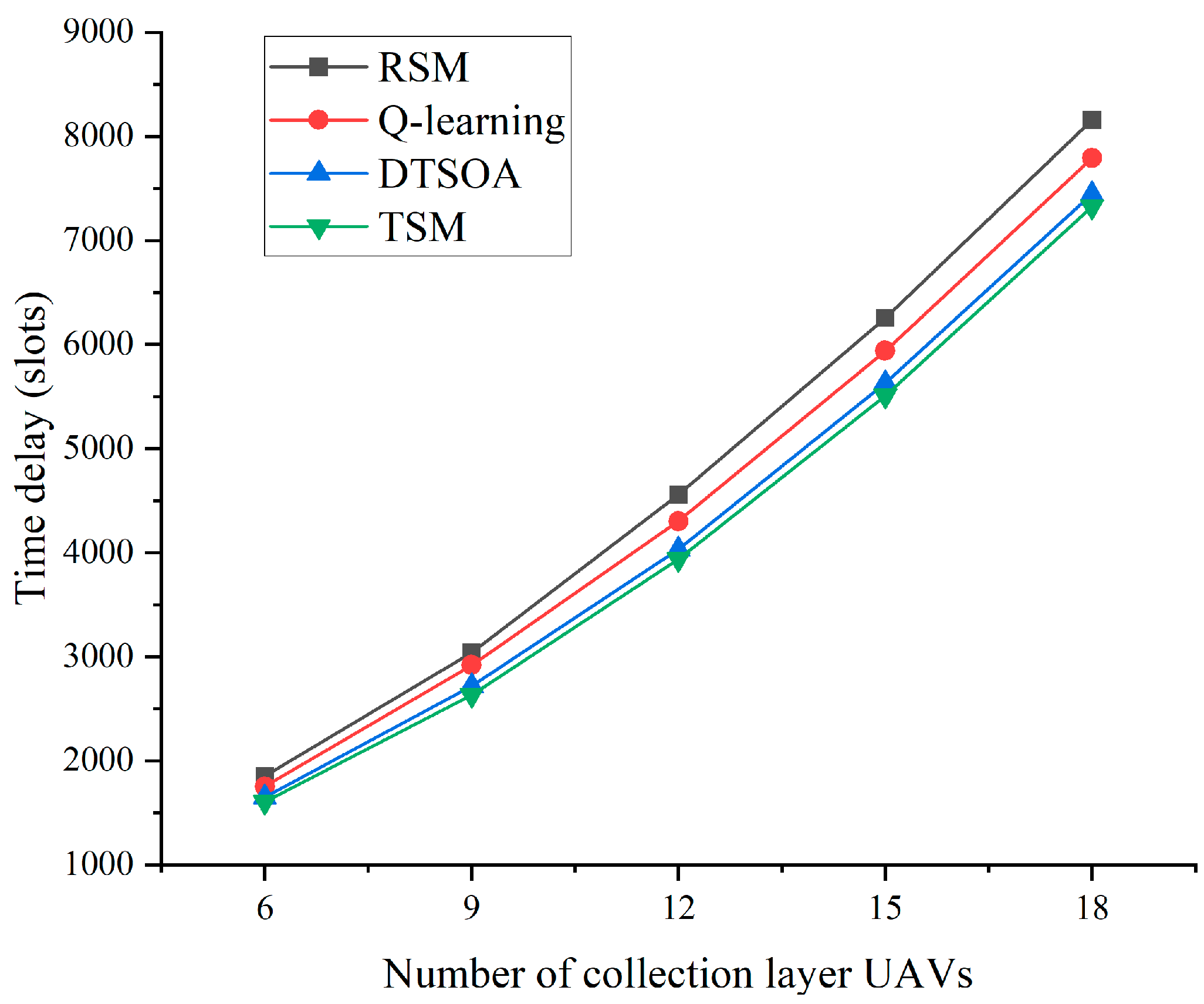
| Nuuav | Number of collection layer UAVs | 6, 9, 12, 15, 18 | Rack |
| Ntuav | Number of transport layer UAVs | 3, 6 | Rack |
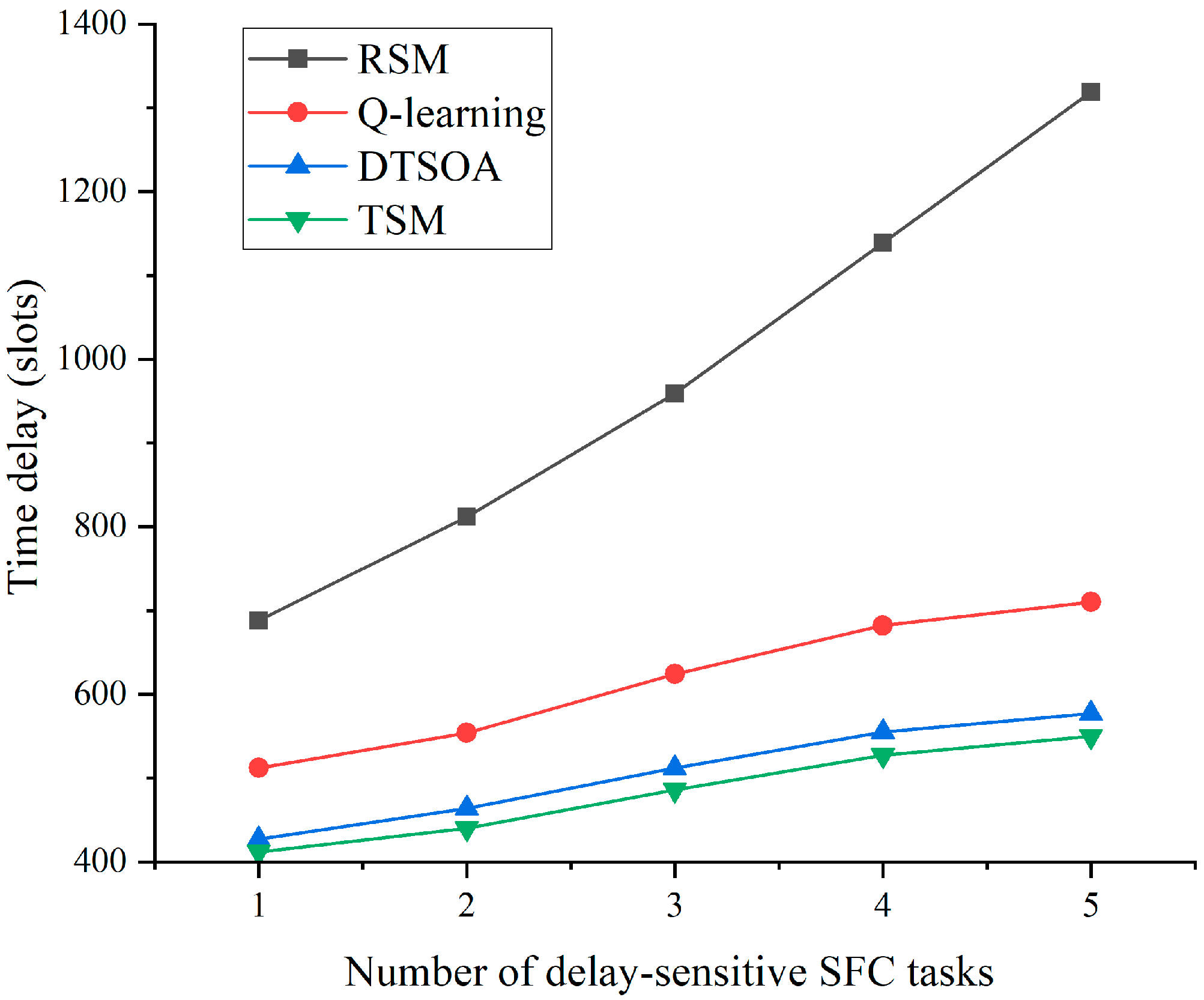
| Nmk | Number of delay-sensitive SFCs bars | 1, 2, 3, 4, 5 | Article |
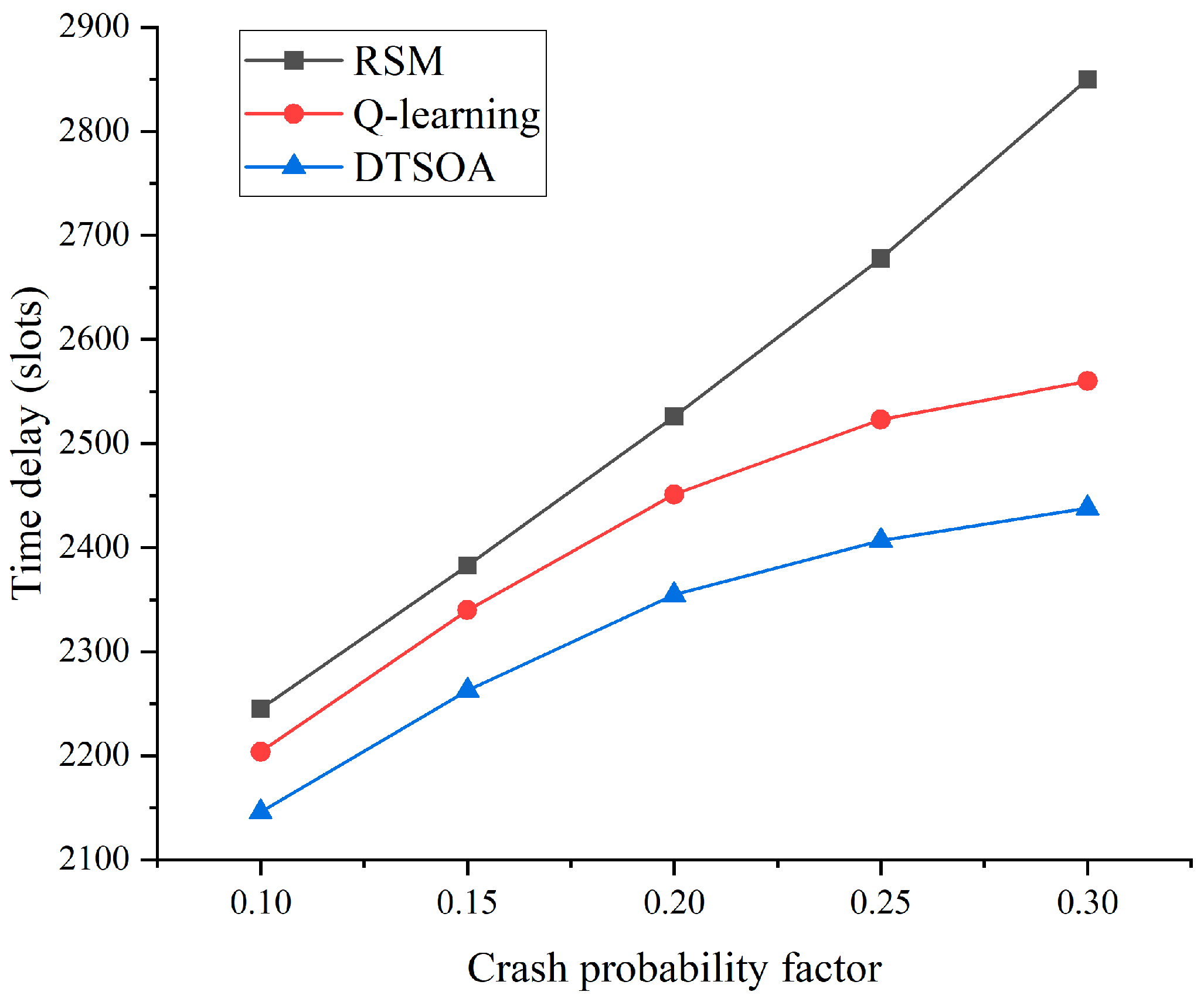
| Device crash probability | 10%, 15%, 20%, 25%, 30% | ||
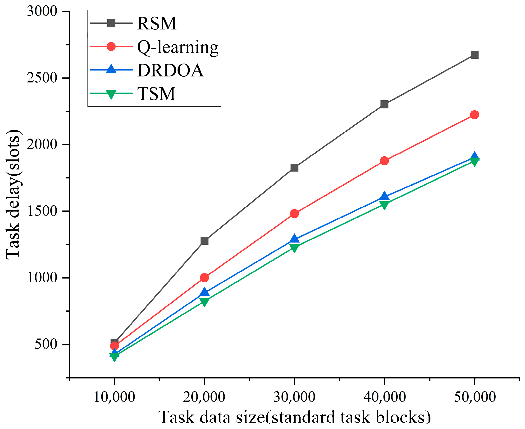
| Ddata | Calculate task data size | 10,000, 20,000, 30,000, 40,000, 50,000 | standard task blocks |
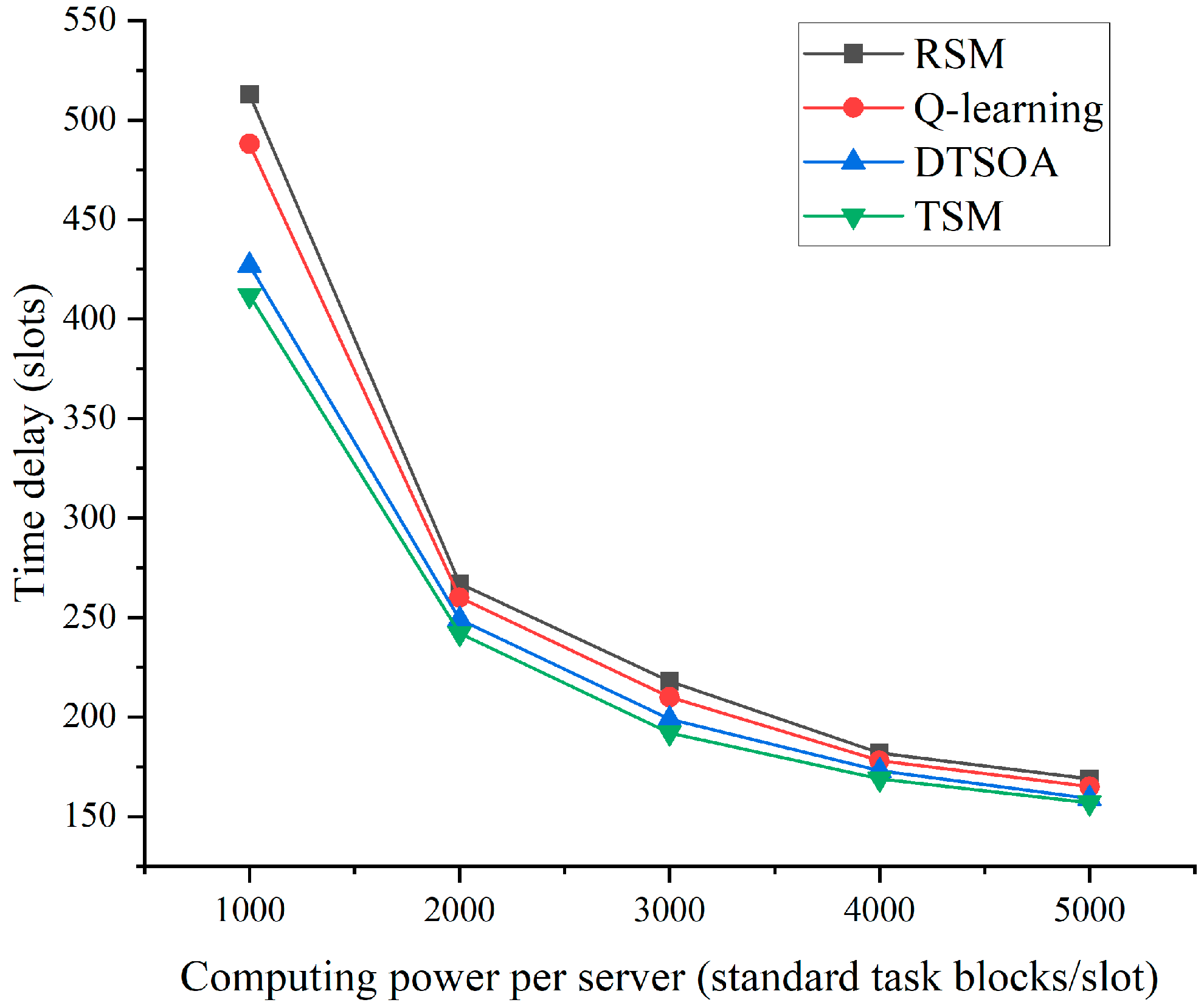
| F | Execution layer UAVs computing power | 1000, 2000, 3000, 4000, 5000 | standard task blocks/slot |
Disclaimer/Publisher’s Note: The statements, opinions and data contained in all publications are solely those of the individual author(s) and contributor(s) and not of MDPI and/or the editor(s). MDPI and/or the editor(s) disclaim responsibility for any injury to people or property resulting from any ideas, methods, instructions or products referred to in the content. |
© 2023 by the authors. Licensee MDPI, Basel, Switzerland. This article is an open access article distributed under the terms and conditions of the Creative Commons Attribution (CC BY) license (https://creativecommons.org/licenses/by/4.0/).
Share and Cite
Li, X.; Fang, Y.; Pan, C.; Cai, Y.; Zhou, M. Resource Scheduling for UAV-Assisted Failure-Prone MEC in Industrial Internet. Drones 2023, 7, 259. https://doi.org/10.3390/drones7040259
Li X, Fang Y, Pan C, Cai Y, Zhou M. Resource Scheduling for UAV-Assisted Failure-Prone MEC in Industrial Internet. Drones. 2023; 7(4):259. https://doi.org/10.3390/drones7040259
Chicago/Turabian StyleLi, Xuehua, Yu Fang, Chunyu Pan, Yuanxin Cai, and Mingyu Zhou. 2023. "Resource Scheduling for UAV-Assisted Failure-Prone MEC in Industrial Internet" Drones 7, no. 4: 259. https://doi.org/10.3390/drones7040259