1. Introduction
Nowadays, Remotely Piloted Aircraft (RPA) operations in the civilian sphere mainly include a single vehicle that performs reconnaissance missions by sending telemetry parameters that different onboarded sensors have acquired (e.g., video, temperature, air quality) to a Remote Pilot Station (RPS). Despite their apparent simplicity, single-RPA applications are employed in many different and significant fields (e.g., surveillance of livestock [
1], monitoring of power lines [
2], traffic monitoring [
3], or search and rescue [
4], among many others).
Over the past few years, implementing more complex services integrated into the urban environment based on multiple RPAs operating collaboratively (the so-called RPA swarms) has been profusely investigated. It has led to new scenarios that have not yet been adequately deployed, such as package delivery [
5], monitoring of crowds such as concerts or demonstrations [
6], communications coverage extension [
7], or support to emergency services in cities such as firefighters, police, and hospitals [
8]. However, there are still several critical challenges before we can see these applications integrated into our daily lives.
On the one hand, these challenges have to do with the regulation field. For example, the European Union has recently released a new single European regulation (EASA:
https://www.easa.europa.eu/domains/civil-drones (accessed on 14 January 2023)) (which is applicable as of 31 December 2020), which affects all Remotely Piloted Aircraft Systems (RPASs) regardless of the weight and size of the RPA and whether they are used for professional or recreational purposes. Some significant rules to comply with the new European regulation are (i) registering as an RPAS operator, (ii) accrediting RPA pilot training, or (iii) meeting the different restrictions/regulations imposed by local airspace authorities for each possible flight area. On the other hand, solving the challenges involves the technological field itself (described below).
This article will address the latter perspective, although its relationship with air traffic management will also be discussed. In particular, we handle one of the challenges RPAs will face in the hyper-connected environment already present in the current 5G communications ecosystem and even more so in the upcoming 6G scene, looking towards all-to-all connectivity scenarios.
In the first place, near-future-RPAs will need to transmit many more information streams. In addition to the traditional video stream, RPAs may need to transmit, for instance, (i) data related to aeronautical telemetry (e.g., pressure, temperature, speed, GPS position), (ii) telemetry from different onboarded sensors (e.g., air quality, smoke detection), (iii) control information for U-Space Unmanned Aircraft System Traffic Management (UTM) [
9], (iv) control information for their RPS, (v) control information between RPAs for swarm management, (vi) information from new applications they may support (e.g., VoIP provisioning for remote users, loudspeaker service for emergencies) or traffic related to the many service-provisioning technologies that are being included more and more within the software payload of the RPAs ranging from virtual machines to containers or light containers that can be remotely handled.
In the second place, RPAs will have many alternatives for data transmission. These alternatives include traditional radio frequency links for Control and Non-Payload Communications (CNPC) (also known as Command and Control (C2)) and payload (usually in separate bands), to which will be added different backup links that may eventually be considered as primary links based on cellular technology (either 3G, 4G/LTE, 5G), satellite technology, proprietary line-of-sight links, millimeter wave, visible light communications, Wi-Fi links, or Bluetooth links. These technologies generally are not interchangeable, and each has its own field of application (e.g., long-distance point-to-point communications, networking, low energy consumption). However, given that they are increasingly being developed in lighter and smaller devices, it is possible to assume that an RPA could use several simultaneously, thus multiplying its versatility and complexity simultaneously.
Finally, a highly volatile and dynamic environment, such as RPA operations, is also disruptive, not only from the intermittent availability of the transmissions themselves (e.g., coverage, obstacles, interference) but also from the intermittent availability of the transmission devices (e.g., transmission failures, RPA batteries running out, new devices, whether RPAs or RPSs that dynamically join or leave the communications network) which continuously forces network topology reconfigurations. This heterogeneity of such a broad spectrum of events, but also so focused on the discontinuity of the service, raises multiple challenges in the provision of these services, which in many cases are expected to reach extensive levels of robustness, reliability, and resilience (3R services), insofar as they are services that are very useful in all kinds of emergency operations or operations in challenging locations or even expensive operations that are difficult to be repeated.
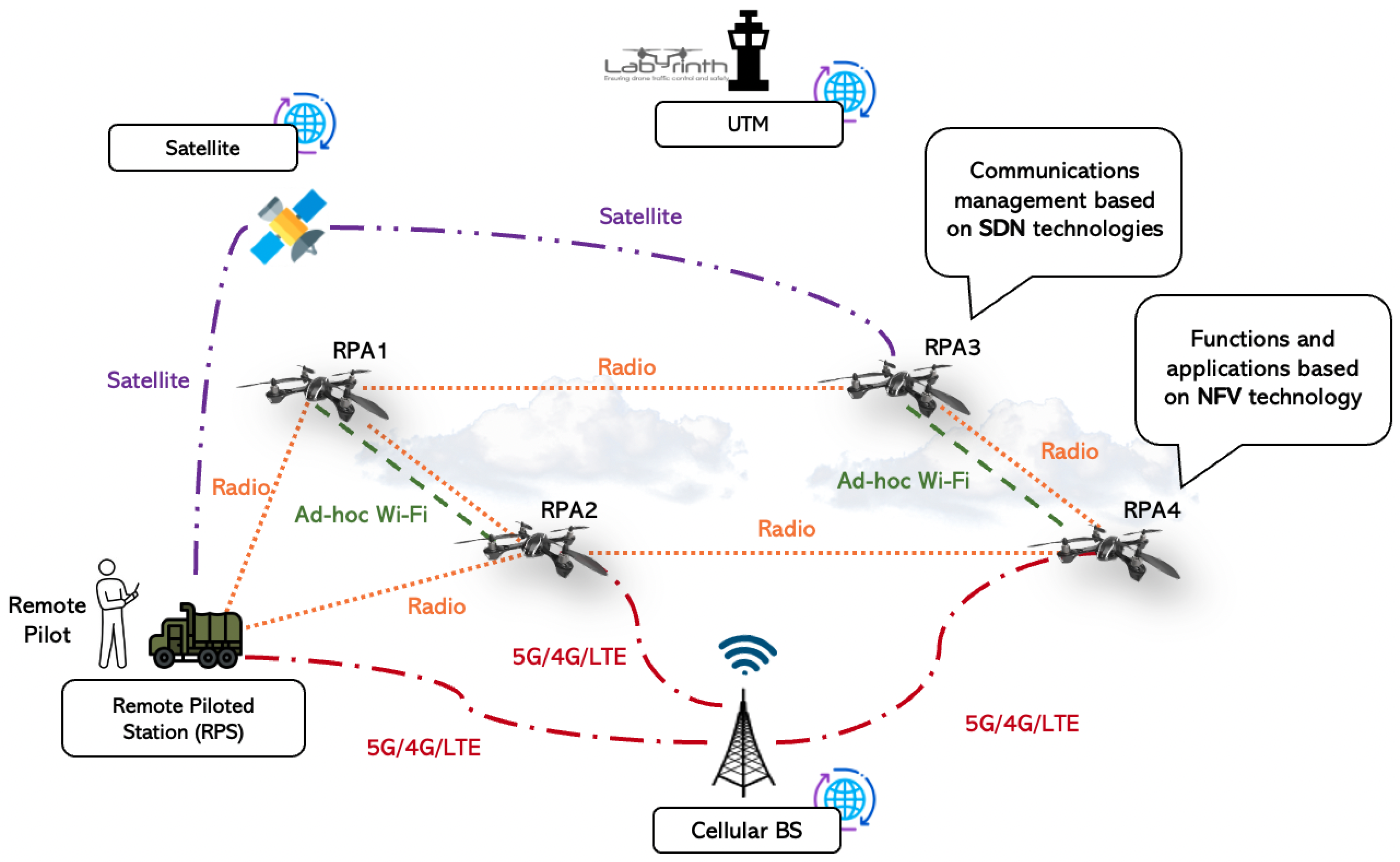
Figure 1 presents the reference scenario for this article, showing a network with multiple RPAs that may use different communication alternatives (not all vehicles are required to have or use the same communication links). However, to complete a successful mission, the RPA may have to cooperate for specific assignments (e.g., RPA1 uses RPA2 or RPS to report parameters to the air traffic control entity).
This is the communication research framework that has been considered within the European project Labyrinth (Labyrinth, Ensuring drone traffic control and safety:
https://labyrinth2020.eu/ (accessed on 14 January 2023)) where different partners, including academia (Universidad Carlos III de Madrid), industry (such as Telefónica I + D, or ARQUIMEA), aeronautical research centres (such as the German Aerospace Center (DLR), or the Spanish National Institute of Aerospace Technologies (INTA)) will develop solutions that will be tested along the year 2023 by different relevant end users (the Municipal Emergency Assistance and Rescue Service—Civil Protection in Madrid, Spain (SAMUR); the Spanish General Directorate of Traffic (DGT); or the Italian Port Authority of the Eastern Ligurian Sea).
This article presents the solution that has been developed to support communications in the context of the Labyrinth project that represents quite well all these frequent scenarios that we will be finding more and more in the RPAS field shortly. The solution involves the dynamic establishment of a network infrastructure that allows all those implicated in the communication to interconnect, extending the number of paths available to a given destination as far as possible. The proposed solution is also valid in use cases beyond traffic management, including road, air, and waterborne transport or supporting emergency services in natural disasters.
A Communication Infrastructure Manager (CIM) will be responsible for this task. It will also manage all the complexity related to the assignment of flows to the multiple interfaces that may be present both in the RPA and the RPS. In a 3R (robustness, reliability, and resilience) environment, this task will imply the constant monitoring of the links in order to dynamically establish the proper metrics to be applied in each circumstance (e.g., path definition and flow assignments can be either based on delay metrics, or in allocated bandwidth, power consumption). For the CIM development, we started from a prior simple version [
10], which has been upgraded to operate with Software-Defined Networking (SDN) technology.
The rest of the article is organized as follows:
Section 2 reviews the state of the art and background.
Section 3 presents the system design.
Section 4 present three proof-of-concept experiments that showcase the potential of the CIM in multi-RPA scenarios. Finally,
Section 5 concludes the article and depicts our future research lines.
2. Related Work
The availability of robust communication links is one of the most crucial factors in enabling the possibility of reliable RPA operations (pursuing the 3R approach). In many works, the communication between devices (RPA-RPA or RPA-RPS) is just taken for granted, and it is assumed that it will always support the whole system. However, depending on the operation scenario, this supposition may only sometimes be true. It can be hard to obtain a good (i.e., robust, redundant) communication channel between RPAs to the RPS or between the RPAs themselves. This challenge is amplified in environments where RPAs may encounter unplanned/unexpected conditions (i.e., urban environments full of obstacles or interference, or the military domain). This point is quite a common problem in traditional communication networks that is even more intensified by the volatile/dynamic nature of these flying network nodes. The different solutions are commonly found in one of the following two domains: One alternative is strengthening the communication channel using a more robust technology or redundant communication channels. The other not necessarily exclusive alternative is strengthening the network, providing redundant paths to the destination (multi-path) or more reliable intermediate nodes.
Using alternative or multiple communication channels has only sometimes been an option for RPAs because it implies onboarding more transmission/reception devices, and the payload, in some cases, may be pretty limited. However, nowadays, RPAs can carry payloads of much more than simple communication gadgets thanks to the rapid evolution in the miniaturization of devices. This fact allows RPAs to become powerful IoT components, offering not only sensing but also communication services and onboard data analysis. For example, authors in [
11] employ LoRa, Wi-Fi, and LTE networks to provide the RPA systems with broadband and cellular wireless network support. This multi-interface concept is increasingly present in the multi-RPA environment and will be treated in this paper. Authors in [
12] propose a solution for RPAs in which 4G and 5G cellular technologies are combined to maximize the operating range in areas where commercial 5G is not yet deployed. Therefore, their system uses the best available alternative based on radio parameters such as the Reference Signal Received Power (RSRP) and Reference Signal Received Quality (RSRQ). The utilization of cellular technologies in RPAs is becoming increasingly relevant, turning the RPAs into flying base stations or mobile end users.
Regarding the second possibility and the usage of redundant paths to a particular destination, there are plenty of initiatives using RPAs as communication relays. For instance, the authors in [
13] present a tactical data link that guarantees control reliability in emergencies and introduces tactical data to link RPAs as communication relays. The authors in [
14] propose using other RPAs that are part of the system as communication relays to enable two-hop connectivity and enhance extensive reliability.
However, nowadays, there is a notorious trend towards the idea of being able to configure flying communication networks based on RPAs acting as network nodes and bringing to aerial communications the same advantages that we may have with a meshed ground network [
15,
16].
Figure 1 shows multiple paths and technologies. This figure also serves as a reference scenario for the Labyrinth project where various network nodes (either RPAs in the air, ground RPS, or a UTM provider) enable the multi-path network configuration possibility through multiple channel alternatives.
One of the most relevant challenges in these flexible and, at the same time, complex scenarios is the management of the communication networks from their initial configuration and establishment through the maintenance of the communications service up to the response to network failures.
The adoption of softwarization technologies has been recently raised in the RPAS research area to provide solutions to this particular issue. The recent arrival of the 5G ecosystem has not only brought new radio technology as commonly thought but has also incorporated key software technologies such as Network Function Virtualization (NFV) and SDN. Our previous work has explored the use of NFV [
7,
17], analyzing its strengths and weakness, but SDN-based solutions had not yet been explored by authors. Additionally, SDN has opened up new opportunities to automate the management of telecommunication services and verticals and facilitate achievement of the performance requirements imposed on 5G and beyond. For this reason, this article includes some SDN contributions to the RPAS research area.
SDN brings significant advantages to multi-RPA environments, such as a centralized global network view or maintaining the status of the whole network, allowing for a flexible network reconfiguration based on different metrics. Therefore, forwarding decisions in each device may be based not on local conclusions, but rather on what happens in the rest of the network. SDN can help to address several inherent challenges of multi-RPA networks (e.g., architectural design, fluid topology, routing protocols, energy consumption) [
18]. SDN can reconfigure the whole network (due to the global view of the SDN controller) under topological changes, which are quite frequent due to the intrinsic mobility of RPAs. For example, to reach RPS from RP4, there are several alternatives (e.g., RPA2 using radio, RPA3 using Wi-Fi or radio, 5G/4G/LTE). At some point, SDN could choose to go through RPA3, but if that link is lost, it may go to RPA2. SDN can also use different strategies for packet forwarding beyond the destination IP/MAC address, taking into account various parameters such as payload or packet types. SDN networks can also avoid network interference since it enables path/channel selection at any moment. Furthermore, SDN may select which channels are more reliable, based not only on instant parameters (e.g., signal level) but also on other representative information that cannot be considered in traditional routers (e.g., RPA mission planning input, historical data).
The above-mentioned advantages slightly represent what the SDN paradigm can bring to multi-RPA networks. However, the design of legacy SDN technology was not done to fit into such specific environments like multi-RPA networks. Consequently, several challenges/issues must still be solved in order to involve SDN in this framework; in this regard, both academia [
19,
20] and industry have increased their interest in this topic during the last years: authors in [
21] propose an SDN and MQTT hybrid system for battlefield multi-RPA environments. Their proposal adapts to the periodic swarm topological changes, supports flexible data transmission among payloads, and improves swarm security. Authors in [
22] design an SDN framework for the RPA backbone network. This framework monitors the RPA network to manage and analyze available information effectively. Authors in [
23] investigate the deployment of an SDN RPA network providing a communication service. This article considers the placement of the SDN controller and its implications in terms of communication overhead and end-to-end delay. As the envisioned development of this article, the last references employ the SDN ecosystem as a key enabler technology for the correct operation of their systems.
In order to maintain control over all the interfaces available in the devices (both the RPA and RPS) as well as the establishment and configuration of the communication networks, we developed the CIM (the evolution of the Interface Manager (IM) developed in [
10]). The CIM employs SDN with the primary objective of keeping a global vision of the network that allows it to select the most suitable communication alternatives enabled by the multiple interfaces and paths at any given moment based on different metrics (e.g., delay, available bandwidth, energy consumption).
3. Communication Infrastructure Manager: Design and Deployment
The CIM is a comprehensive communications operator/manager designed for RPAS environments. The CIM allows the creation and establishment of networks between the different RPAS actors (RPA and RPS) and the selection among the accessible communication channels.
Traditional RPAS communication systems used to be static designs that used a single RF interface to communicate between the RPA and the RPS. The evolution and miniaturization of electronics, in combination with the emergence of new requirements and needs, have resulted in fully connected systems with several communication interfaces available.
The CIM is a software entity deployed in each RPAS element (RPA and RPS). The deployment of an entity such as the CIM allows one to take advantage of all current resources automatically and efficiently by addressing the problem from two different approaches: (i) taking advantage of transmission interfaces; (ii) establishment of networks, not only point-to-point but multi-hop networks and also multi-technology paths (e.g., first hop using Wi-Fi, second hop using RF).
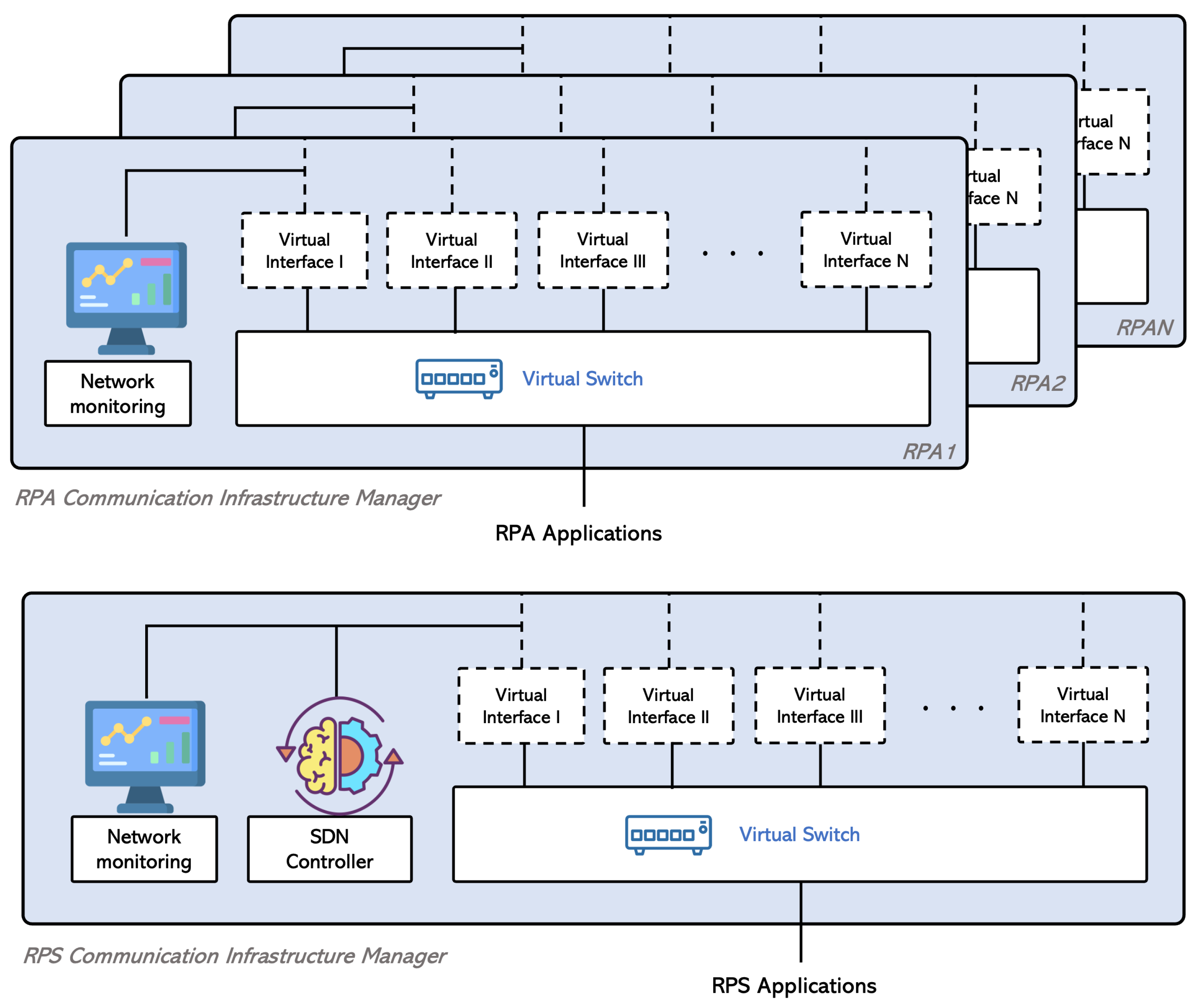
The architecture of the CIM can be summarized in
Figure 2. As the picture shows, the CIM relies on different technologies for its correct operation. On the first hand, the CIM employs SDN. Taking advantage of SDN, we acquire a centralized and global management plane that makes it possible to decide and program the behavior of the RPAS network, bringing with it many of the advantages inherent to SDN networks, such as better control and management of data, efficiency in the optimal management of available resources, or unifying data and infrastructure. On the other hand, it uses virtual networks. Virtual networks are created to complete dynamic tunnels over the existing RPA infrastructure. In this way, the selected virtual network changes thanks to the decisions made by the SDN controller, and these changes are made transparently for both RPA and RPS applications.
Finally, the CIM uses a network monitoring application that collects information and metrics from the network (e.g., RTT, packet loss, available bandwidth, jitter, power consumption) and reports this information to the SDN controller as input for making decisions affecting the network. This system, therefore, incorporates significant flexibility and offers many deployment possibilities. This article presents the reference scenario used for the use cases of the Labyrinth project.
The following subsections describe the steps to bring the system up, covering all the implementation details and explaining the scenario components in depth.
3.1. Reference Scenario
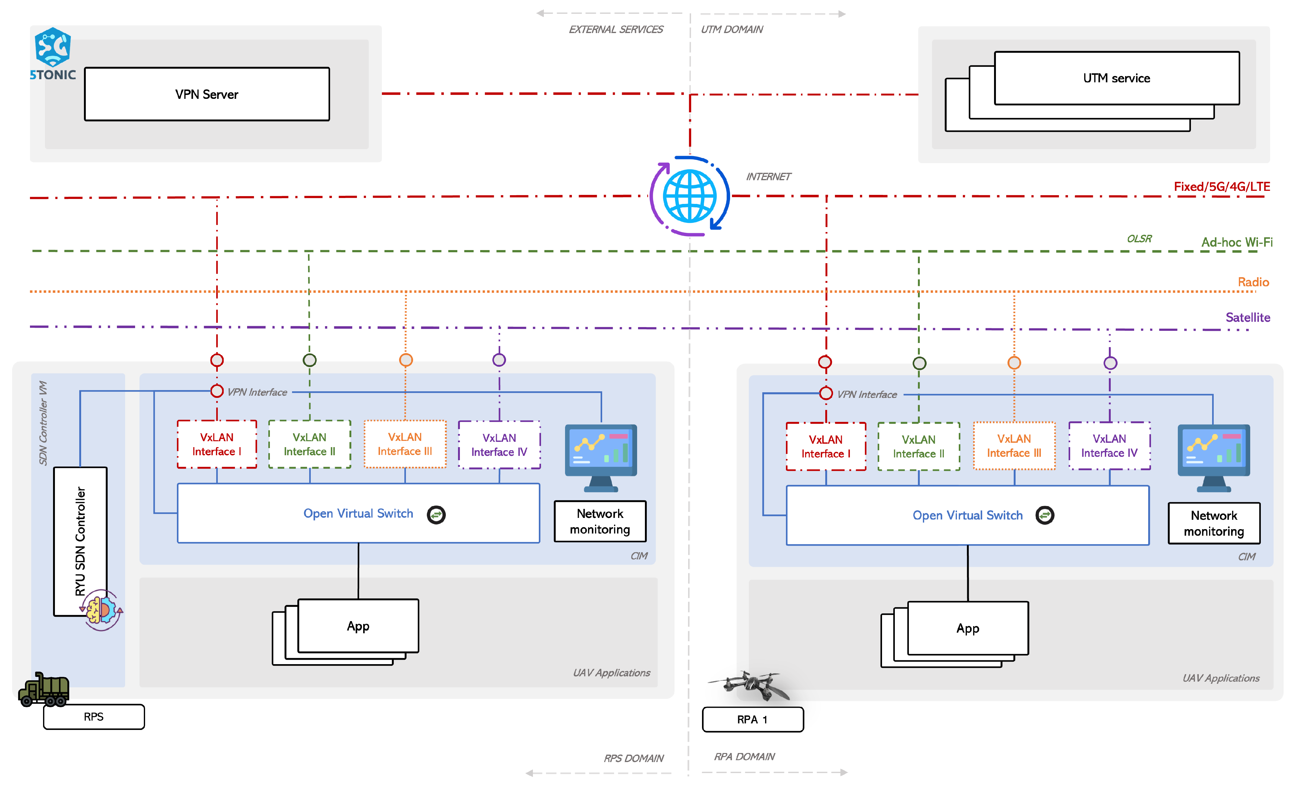
To study the feasibility and functionality of the CIM in multi-RPA environments, we propose a reference scenario (depicted in
Figure 3). The reference scenario includes the three domains present in the Labyrinth project (RPA, RPS, and UTM) for a correct operation. Additionally, it includes the external services domain required for enabling communications using the public Internet.
As it can be appreciated, the CIM entity (shadowed in blue) is located within the RPA and RPS domains since both domains may include several communication alternatives. The figure indicates that each domain includes four communication alternatives in this particular case. However, the number of interfaces may vary depending on each case. The figure also shows the SDN controller (located in the RPS) that acts as the network’s brain.
The following subsections detail the required steps to properly configure the reference scenario for further experimentation.
3.2. Network Layer Connectivity
The first step is to enable connectivity at the network level (IP level) between the RPA and RPS domains. This procedure may be straightforward in some cases; however, it may require additional configuration in others that may be too technology dependant. Each device may have different interfaces (e.g., 5G, proprietary radio, Wi-Fi, satellite) and must be appropriately configured.
For example, to enable multi-hop communication in Wi-Fi (ad hoc), the use of a routing protocol is required. This way, when two devices are not in the Wi-Fi range, but have a path using other intermediate nodes as a relay, communication at the network level will be automatically enabled.Optimized Link State Routing (OLSR) [
24] protocol has been used in our case. OLSR is a well-known legacy MANET protocol that enables multi-hop connectivity, exemplified in our previous work [
25], performing acceptably for the proposed scenarios.
Another representative example is cellular communication, the end-to-end communication between two devices using the public Internet. Typically, devices connect to the Internet using a private IP address (configured by the Internet provider) and a Network Address Translation (NAT). Therefore, these devices can browse the Internet but are not accessible from external machines. In order to solve this mentioned problem, a Virtual Private Network (VPN) server has been configured. Therefore, all devices connect to the VPN server, which acts as a relay to enable device-to-device connectivity. The performance does not significantly drop when using the VPN server as a relay (this effect has previously been studied in [
7]). The VPN server has been deployed at the 5G Telefonica Open Network Innovation Centre (5TONIC) (5TONIC:
https://www.5TONIC.org/ (accessed on 14 January 2023)) laboratory. This server (seen in
Figure 3) is considered an external service. This fact means that they are services that are not in the RPS, the RPA, or the UTM domain but are required for everything to work as expected. Another example of these external services in Labyrinth is the one dedicated to the path calculation algorithm responsible for enabling a feasible 3D path for the RPA based on UTM constraints. It has not been included in the picture since this algorithm is out of the scope of this article, but more details can be obtained in this reference [
26].
3.3. Data Layer Connectivity (On Top of Network Layer)
Once the device-to-device connectivity has been appropriately configured for all the available interfaces (
Section 3.2), the goal is now to transmit data link layer traffic over the network layer (i.e., Ethernet traffic over an IP network). Overlay networks are used for this purpose.
An overlay network is a virtual network of logically linked nodes built on top of one or more underlying networks. The overlay network nodes are connected by virtual links to implement network services that are not available in the underlying network(s). The reason for using overlay networks in this scenario is because they provide isolated domains, i.e., the traffic transmitted over the overlay is isolated from any other traffic going over the network, allowing for control and data traffic differentiation (e.g., VPN, OLSR, network monitoring app). Furthermore, creating an overlay requires no additional configuration of the intermediate nodes.
In our case, we use Virtual Extensible LAN (VxLAN) [
27], an encapsulation protocol designed for this purpose. In this way, traffic entering a VxLAN tunnel exits at the tunnel’s other end(s) as if both devices were on the same Local Area Network (LAN). The establishment of virtual point-to-point links (VxLANs) through a layer-3 VPN has been validated in the context of the H2020 European project 5G-ZORRO, where authors of the paper are involved.
3.4. Software-Defined Networks
3.4.1. SDN Switches
At this point, to enable inter-domain communications (from RPS and RPA apps in
Figure 3), it is necessary to deploy a programmable switch to forward traffic from the domains (RPS/RPA apps in
Figure 3) over the overlay networks (VXLANs in
Figure 3). This programmable switch has different ports to which the applications and VXLANs are connected. Therefore, specific rules should be installed on this switch to forward incoming traffic toward the desired output port.
Open virtual Switch (OvS) (Open vSwitch. Available:
https://www.openvswitch.org/ (accessed on 9 February 2023)) has been selected for this purpose. OvS is one of the most popular implementations of virtual programmable switches agreeing with OpenFlow. The basic functionality can also be realized with Linux Bridges, as seen in the previous version of this work [
10]. However, the operation of OvS, which can be through an SDN controller (explained in the following
Section 3.4.2) or standalone, provides definite advantages. Firstly, by using OvS and an SDN controller, it is feasible to react dynamically to the high rate of changes in the network (very common in multi-RPA environments) by modifying the network configuration. On the other hand, OvS offers great granularity by adding different rules that operate simultaneously and are the ones that allow the instantiation of the selected metric to be honored by the CIM in a particular scenario.
3.4.2. SDN Controller
An SDN controller in an SDN network takes the role of the brain of the SDN network. As we have advanced in
Section 3.4.1, the rules installed in the SDN switches for traffic to be forwarded between the different ports can be standalone (directly installed in the switch) or through an SDN controller. The main advantage of using an SDN controller is that these forwarding rules can be modified when significant changes in the network that invalidate previous configurations occur (e.g., topological changes, intermittent links, channel overload).
The controller and the virtual switches communicate via the OpenFlow protocol (control plane). We have decided to deploy the SDN controller in a virtual machine in the RPS. This controller is in the RPS because there is no space limitation in the equipment used. It is then possible to have equipment with better resources that allow more developments to be deployed. The SDN controller selected is RYU (RYU. Available:
https://ryu-sdn.org/ (accessed on 9 February 2023)). RYU is an open-source SDN controller that provides software components and an Application Programming Interface (API) that facilitate the development of SDN management and control.
We decided to use the cellular interface to communicate the SDN controller and switches. This selection is because cellular connectivity will always be available during the missions in the Labyrinth project (where the correct functioning of this scenario will be tested).
It is important to remark that although for the control traffic the connectivity availability is one of the most relevant requirements (and that is why the cellular option is chosen), it may not be the case for other traffic data flows where, for instance, the low delay provided by Wi-Fi networks may be more interesting, or battery consumption may be more relevant (and may be higher in cellular interfaces), or the usage of public networks may be restricted (since some data/video traffic may be private/sensitive in some circumstances).
3.4.3. Network Monitoring Application
As explained in
Section 2, SDN technologies such as OpenFlow have not been designed with the special considerations/characteristics of multi-RPA environments in mind. For example, SDN switches (
Section 3.4.1) react to different events in a wired network. When one of these events occurs, the corresponding switch reports the SDN controller (using the OpenFlow protocol) which, with this information and those of the other switches in the network, can make the appropriate decisions. However, these events do not operate correctly in decentralized wireless networks, such as the ad hoc Wi-Fi networks we often find in multi-RPA environments. For example, due to the nature of ad hoc wireless networks, it is impossible to determine when a network participant is reachable or not [
28], except with an external application such as the one we need to implement.
To solve this problem, we have implemented a network monitoring application that collects different metrics not only about the network status but also from the status of the device that hosts the switch. This information is periodically sent to the controller, whether there are changes or not. With this information, the SDN controller acquires real-time knowledge about what is ensuing in the network. In this case, each network participant (RPAs and RPS) has a built-in Python script that collects the different metrics. Since the network monitoring application is custom-built in Python, it can collect many metrics (as many as programmed). Some examples are the available bandwidth, the jitter, or the resilience. For this study, we consider the following metrics:
Connectivity [Boolean]: the connectivity metric indicates whether connectivity exists between two network participants (for all the available interfaces).
Round Trip Time [ms]: this metric indicates the current Round Trip Time (RTT) value between two hosts (for all the available interfaces). This measurement is performed using the Linux ping tool.
RX/TX Traffic [bit/s]: this metric indicates the number of received and transmitted bits on each available network interface (e.g., Wi-Fi, 5G, 4G/LTE).
Power consumption [W]: this metric indicates the current power consumption of each host. This measurement is performed using the UM34C USB multimeter.
It should be noted that the connectivity metric not only refers to neighbouring nodes, i.e., single-hop communication, but also considers multi-hop communication.
This information from the network monitoring application applies not only to the SDN controller (to make the appropriate forwarding decisions at any given moment), it is also of particular interest to other actors, such as RPS operators, who can observe in real-time what is happening in the network. On the other hand, this information is stored in a database for two primary purposes: (i) to perform an exhaustive ex-post analysis if something has not worked as expected, and (ii) as a communication flight recorder system (also known as black box) in the case of an accident or emergency.
The network monitoring application has been released as open-source [
29]. The scripts have been developed for Ubuntu 18.04 LTS but can be easily adapted to any operating system. The data are transmitted in JSON format to incorporate custom metrics efficiently.
5. Conclusions and Future Work
This article introduces the CIM for multi-interface RPA environments following an SDN approach. It demonstrates that the CIM improves communications management in multi-RPA environments for creating and establishing networks using different technologies and for selecting the most appropriate communications depending on different strategies/policies. These strategies include the automatic selection of the best channel based on any network parameter/metric, load balancing, or static/predefined policies. It also presents a reference scenario, where all the stages to properly achieve communication between the domains through all the available interfaces are detailed.
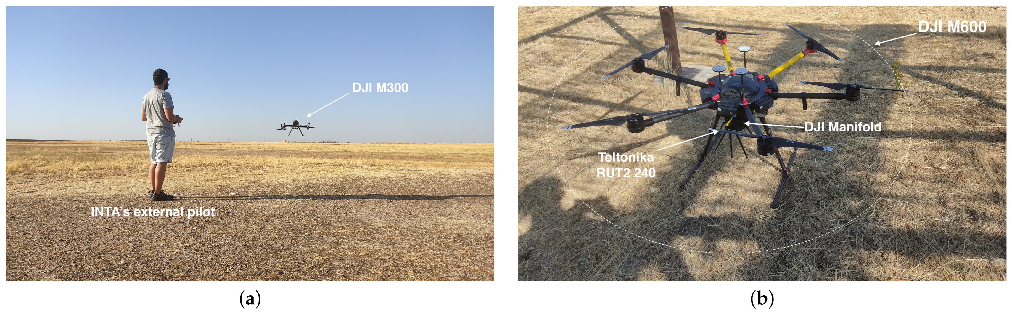
Moreover, once the system is introduced, two laboratory experiences have been reported to showcase the CIM prospect compared to traditional RPA systems, where the communication between RPA and RPS domains only involves the radio interface. These experiments have produced a testbed available in the 5TONIC laboratory, where all the Labyrinth project advances will be tested. In addition, initial flight tests have demonstrated the transferability between laboratory developments and their application in real equipment.
In the same way, this testbed will be used to work on the different research lines listed hereafter.
Shortly, we will work on further flight experiments, taking into account not only the creation of the infrastructure and the enabling of the different communication channels but also testing the possibility of making changes to the communication interfaces based on the different parameters collected by the network monitoring application.
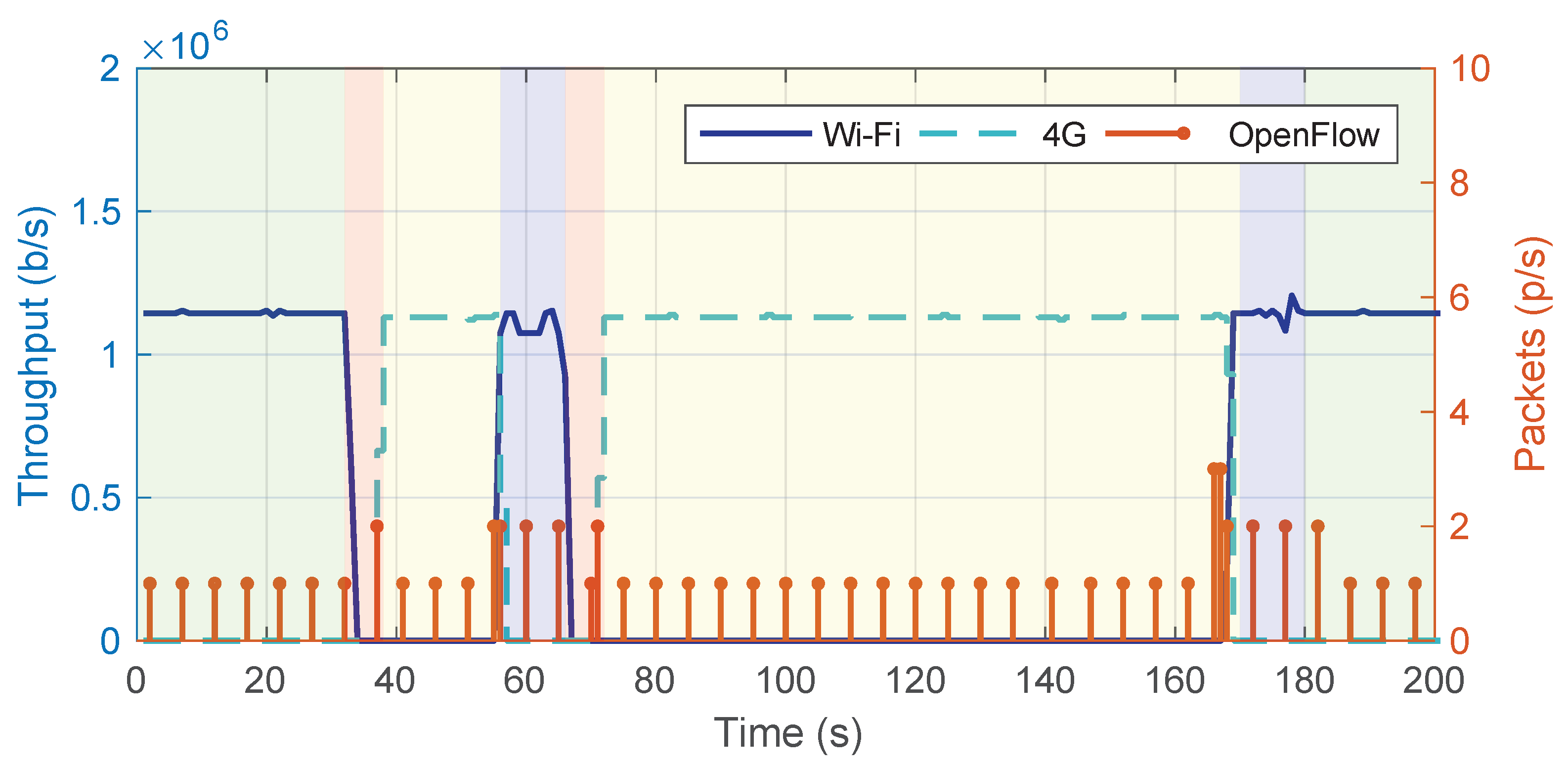
Secondly, the initial version of the CIM sends, by default, all the control traffic (from the OvS to the controller and vice versa) through the 4G/LTE interface, as it is considered that it will always be active. However, in specific scenarios, this assumption will only sometimes be valid. It is, therefore, necessary to work on different mechanisms that allow us to send control information through the different interfaces to ensure that it reaches its destination.
Lastly, we will consider integrating into the CIM software innovative solutions such as intent-based networking [
31] for defining communication requirements that the RPA network is assumed to deliver.


