
Service Function Chain Scheduling in Heterogeneous Multi-UAV Edge Computing
 , , ,
, , ,
Abstract
:1. Introduction
- (1)
- The SFC scheduling problem in heterogeneous “CPU + FPGA” computation architecture is formulated as a 0–1 nonlinear integer programming problem. The overall revenue of the system and the completion time sum of tasks are optimized with various resource constraints. To the best of our knowledge, this is the fist paper that has studied the SFC scheduling problem considering FPGA resources in the multi-UAV edge computing network;
- (2)
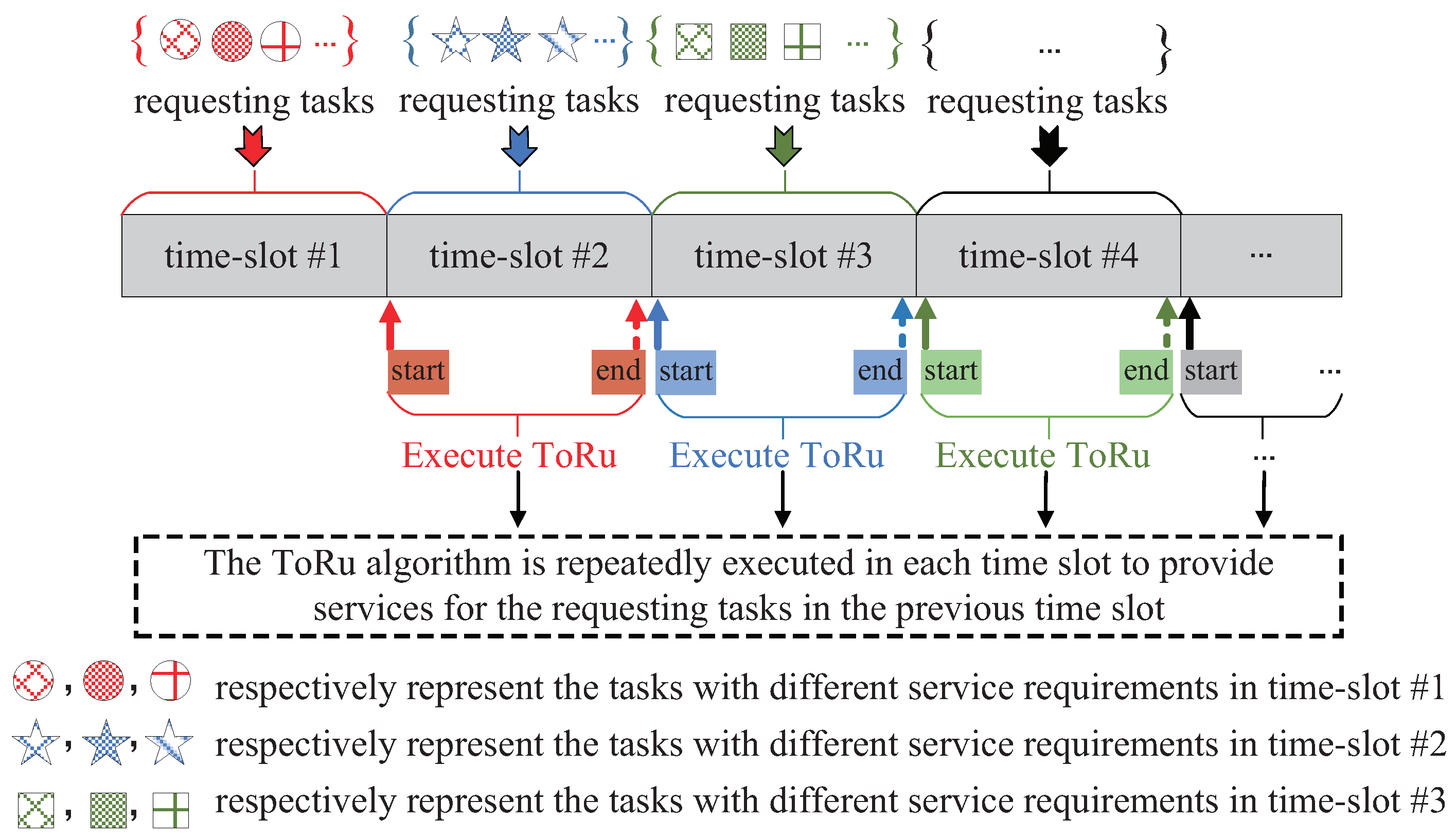
- To solve the NP-hard problem with coupling variables, a two-stage heuristic algorithm called ToRu is put forward. At the first stage, i.e., when the resources are abundant, the SFCs of all tasks are deployed to UAV edge servers in parallel based on our proposed pairing principle between SFCs and UAVs for minimizing the sum of all tasks’ completion time; at the second stage, i.e., when the resources are insufficient, a revenue maximization heuristic method is adopted to deploy the arrived SFCs in a serial service mode. In order to obtain the long-term optimization, a time-slot partitioning protocol is designed, based on which ToRu can operate repeatedly in each time-slot;
- (3)
- A series of experiments are conducted to evaluate the performance of our proposal. Experimental results show that our proposed ToRu algorithm outperforms other benchmark algorithms in the the sum of all tasks’ completion time, the overall revenue, and the task execution success ratio.
2. Related Work
2.1. Task Scheduling
2.2. SFC Scheduling
3. System Model and Problem Formulation
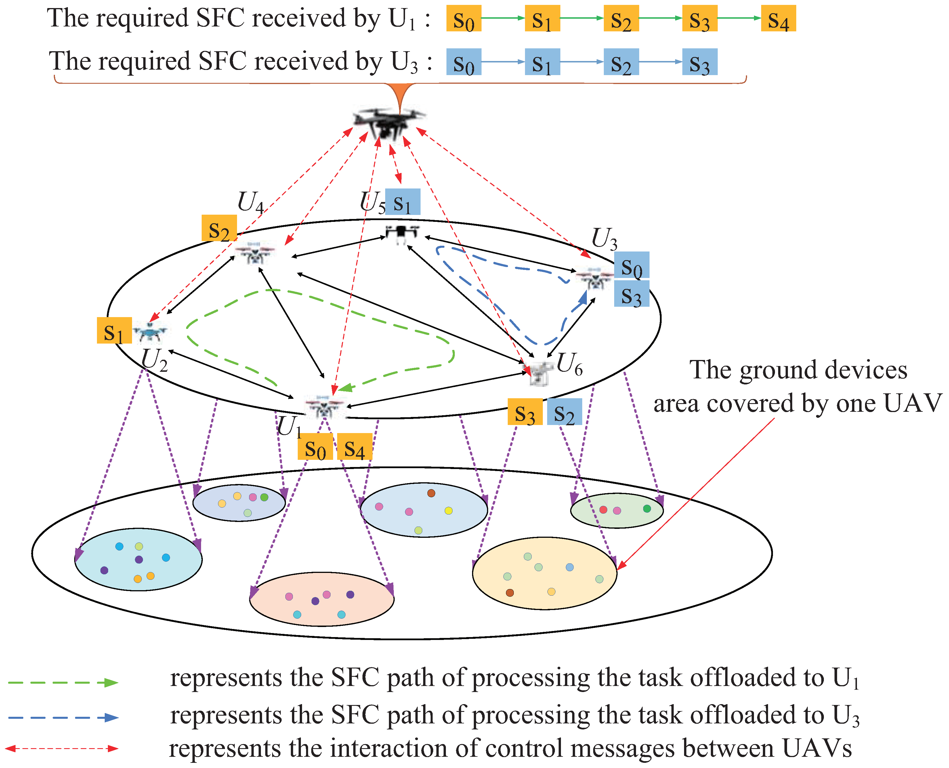
3.1. Network Model
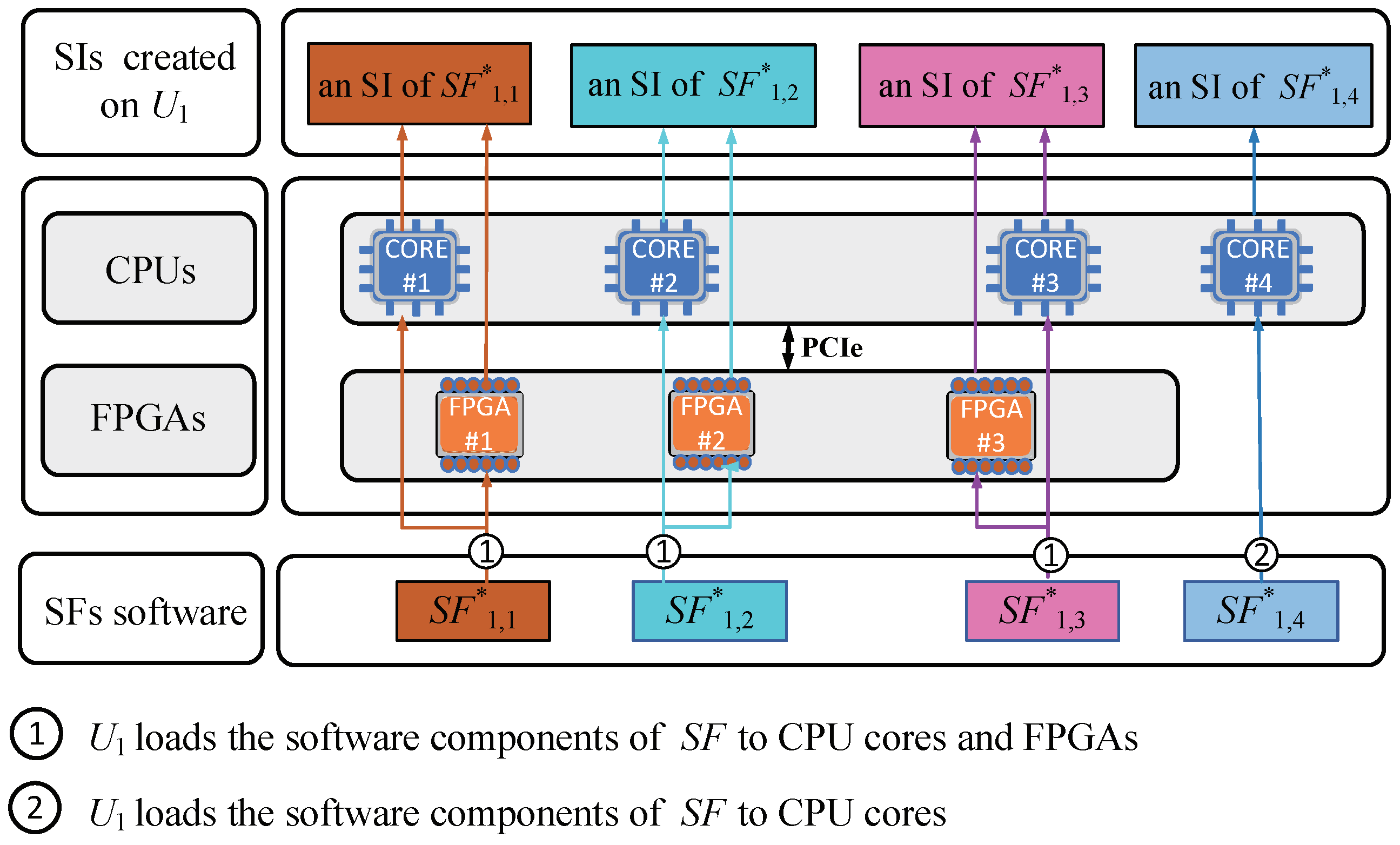
3.2. Service Model
3.3. Task Model
3.4. Problem Formulation
4. Proposed Approach
4.1. The ToRu Framework
| Algorithm 1: General Framework of ToRu. |
Input: the task set , the idle communication resource set , and the idle computation resource set . Output:.
|
| Algorithm 2: Minimizing the completion time sum. |
Input: the task set , the idle communication resource set , the idle computation resource set . Output: .
|
| Algorithm 3: Maximizing the overall revenue. |
Input: the task set , the idle communication resource set , and the idle computation resource set . Output:.
|
4.2. Suboptimal Solution to Minimize the Completion Time Sum
- (1)
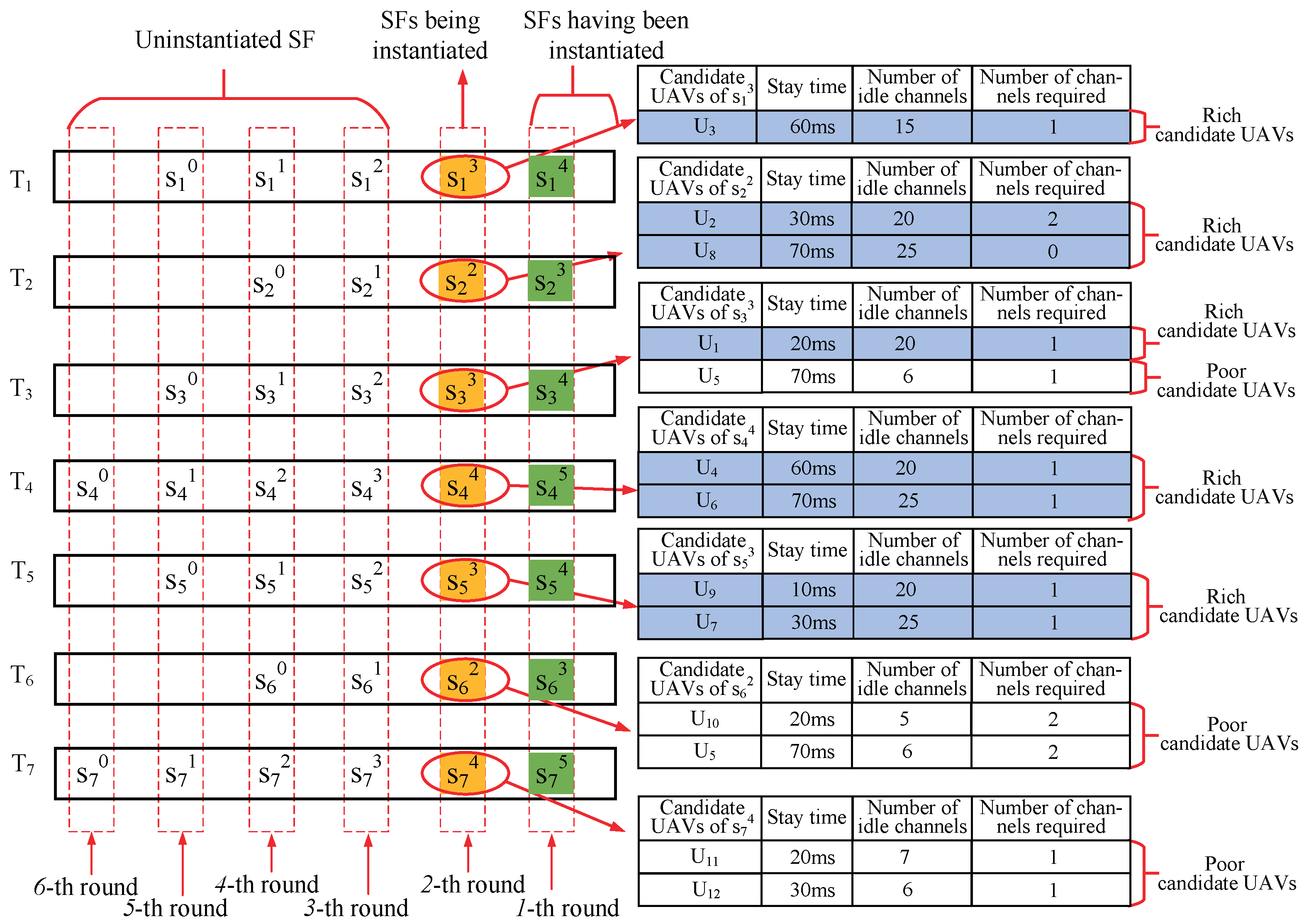
- The upstream SF with only one candidate UAV firstly are instantiated, which is beneficial to maximizing . As shown in Figure 4, contained in has one candidate UAV, so it is firstly instantiated. When facing multiple such upstream SFs (like ), randomly select one of them for instantiation;
- (2)
- When all upstream SFs have multiple candidate UAVs, select the upstream SF with the candidate UAV that does not occupy the sub-channel, and instantiate it on this candidate UAV. As shown in Figure 4, contained in has multiple candidate UAVs, and if it is instantiated on the candidate , no sub-channel is occupied. Therefore, should be first initialized in the current situation. When facing multiple such upstream SFs (like ), randomly select one of them for instantiation;
- (3)
- If there is no upstream SF that satisfies the above principle 1 or principle 2, the candidate UAVs of each upstream SF are divided into two categories based on the number of idle channels: the candidate UAVs with the number of idle channels greater than are called “rich candidate UAVs”, the remaining UAVs are called “poor candidate UAVs”. Considering the shortage of UAV wireless link resources, the upstream SFs should be instantiated preferentially on candidate UAVs with abundant link resources, i.e.,“rich candidate UAVs”, which is beneficial to maximizing . Therefore, we first select an optimal UAV for the upstream SF with “rich candidate UAVs”, the specific principles are as follows:
- (a)
- The upstream SFs with only one “rich candidate UAV” are first instantiated. As shown in Figure 4, contained in has only one “rich candidate UAV”, so it is instantiated first. When facing multiple such upstream SFs (e.g., ), randomly select one of them for instantiation;
- (b)
- When the remaining upstream SFs have multiple “rich candidate UAVs”, we rank their candidate UAVs according to the stay time of a task executed on them, and the candidate UAV with short stay time is ranked higher. The upstream SF with the largest gap in the stay time between its first-ranked candidate UAV and its second-ranked candidate one will first be instantiated on the first candidate one, which is beneficial to minimizing . As shown in Figure 4, both contained in and contained in have two “rich candidate UAV”. The gap in the stay time of () on its different candidate UAVs is 10 ms (20 ms), so is first instantiated on the candidate . When the gap is the same, select one of them at random for instantiation
4.3. Suboptimal Solution to Maximize the Overall Revenue
- (1)
- The UAV network first instantiates the SFC for a task with the greatest value of . When facing multiple tasks with the same payment, the UAV randomly selects one to serve;
- (2)
- An SF is preferentially instantiated on the candidate UAV that does not occupy the sub-channel;
- (3)
- If there is no task that satisfies the above principle 2, the candidate UAVs of each task are divided into “rich candidate UAVs” and “poor candidate UAVs“ according to the principle in Section 4.2. Then, we do the following:
- (a)
- When the number of “rich candidate UAVs” is greater than 0, the candidate UAV with the lowest performance is selected, and the high-performance UAVs are left for subsequent tasks with higher computation requirement, which is beneficial to maximizing ;
- (b)
- When the number of “rich candidate UAVs” is equal to 0, the above operations are performed among “poor candidate UAVs”.
4.4. Computational Complexity Analysis
5. Simulation and Results Analysis
5.1. Experimental Settings
- (1)
- “Revenue + Random”: it first selects the task with the highest payment and performs SFC scheduling for it; next, when instantiating one SF contained in an SFC, it always randomly selects one from the candidate UAVs to instantiate this SF.
- (2)
- “Revenue + Greedy”: this algorithm first selects the task with the highest payment and performs SFC scheduling for it; next, when instantiating one SF contained in an SFC, it always selects the best performance one from the candidate UAVs to instantiate this SF.
- (3)
- “Revenue + Local”: this algorithm first selects the task with the highest payment and performs SFC scheduling for it; next, when instantiating one SF contained in an SFC, it always selects the local one from the candidate UAVs to instantiate this SF.
- (4)
- “Length + Random”: this algorithm first selects the task with the shortest SFC length and performs SFC scheduling for it; next, when instantiating one SF contained in an SFC, it always randomly selects one from the candidate UAVs to instantiate this SF.
- (5)
- “Length + Greedy”: this algorithm first selects the task with the shortest SFC length and performs SFC scheduling for it; next, when instantiating one SF contained in an SFC, it always selects the best performance one from the candidate UAVs to instantiate this SF.
- (6)
- “Length + Local”: this algorithm first selects the task with the shortest SFC length and performs SFC scheduling for it; next, when instantiating one SF contained in an SFC, it always selects the local one from the candidate UAVs to instantiate this SF.
5.2. Results and Analysis
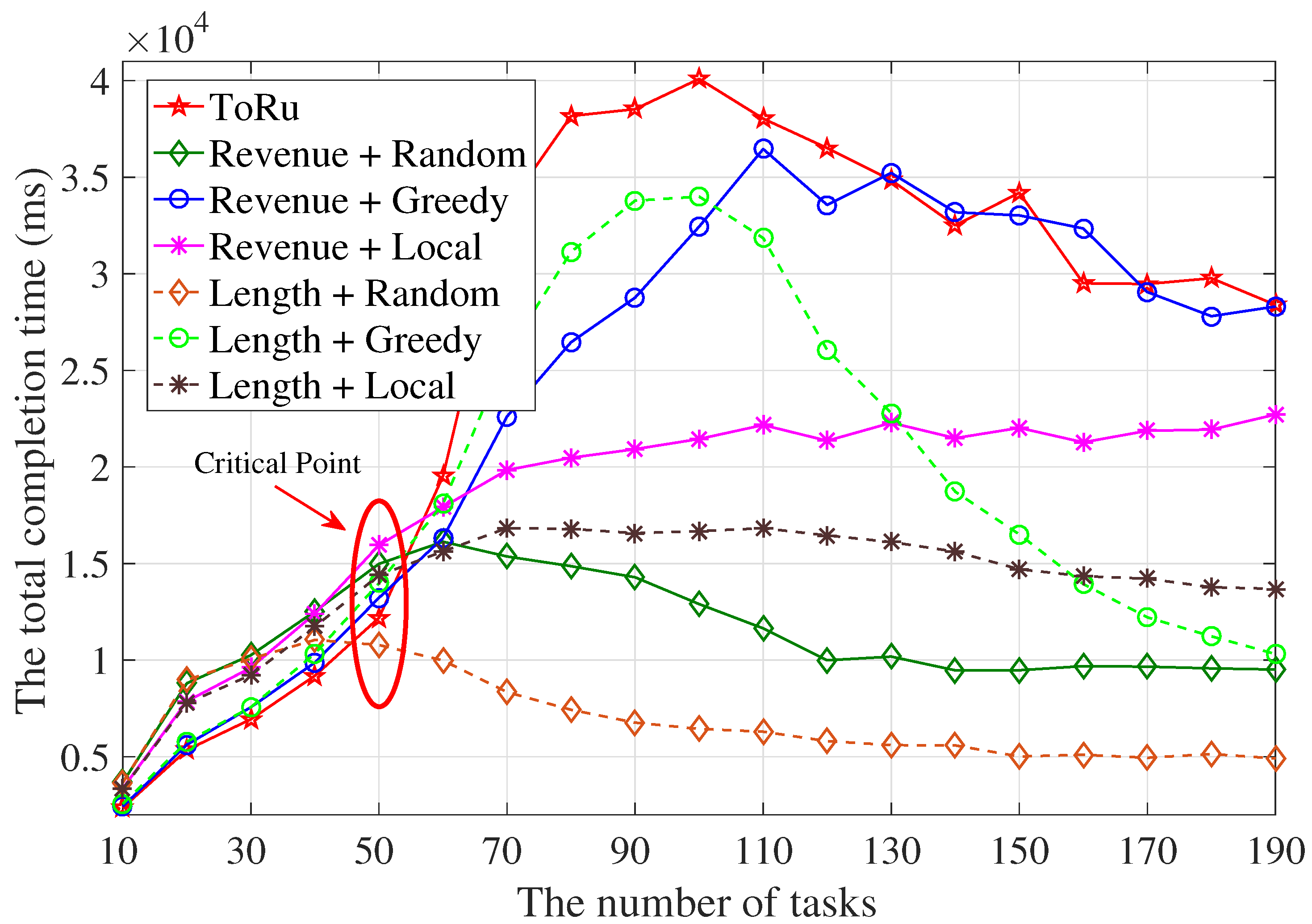
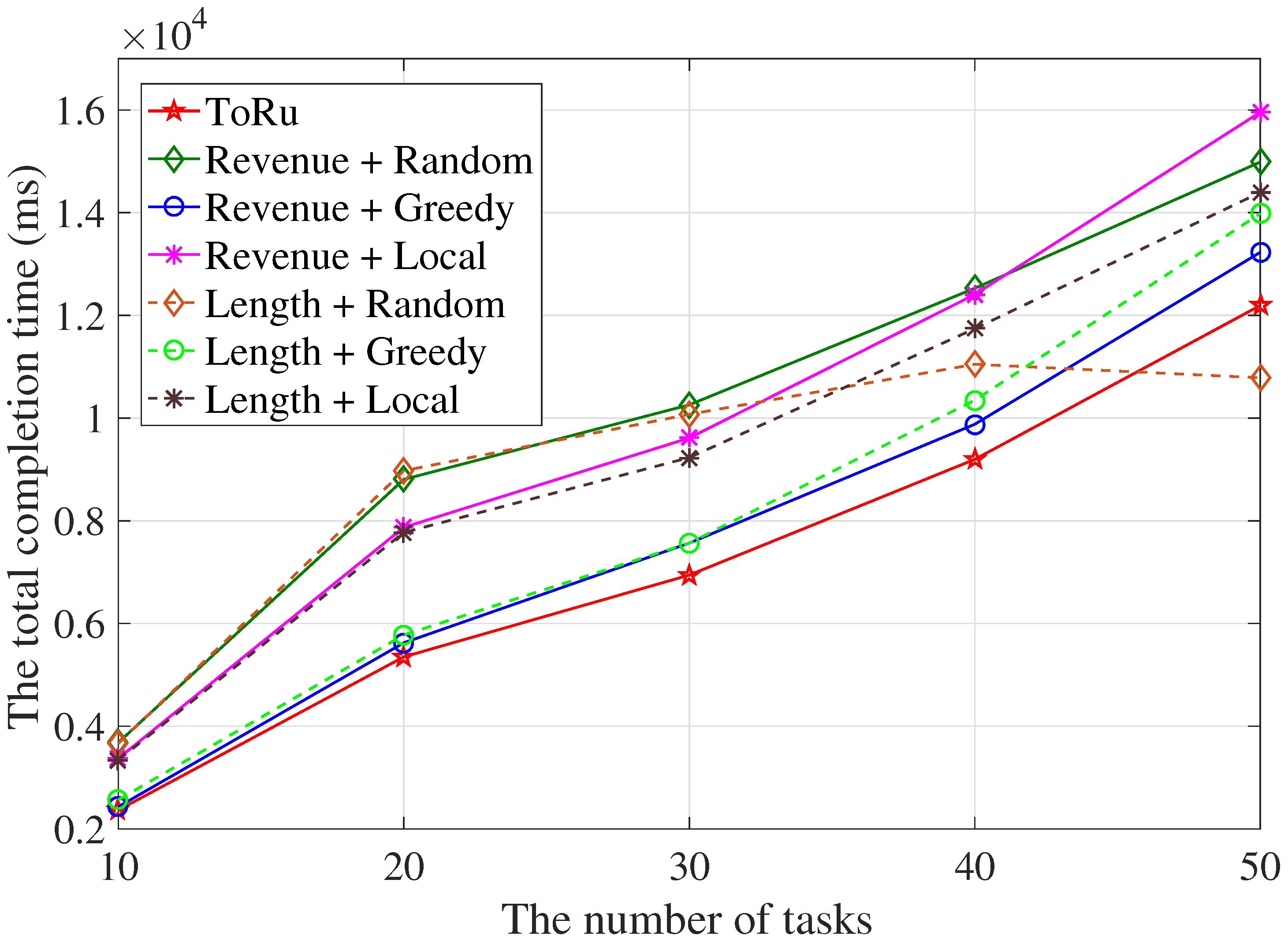
5.2.1. The Completion Time Sum of Tasks
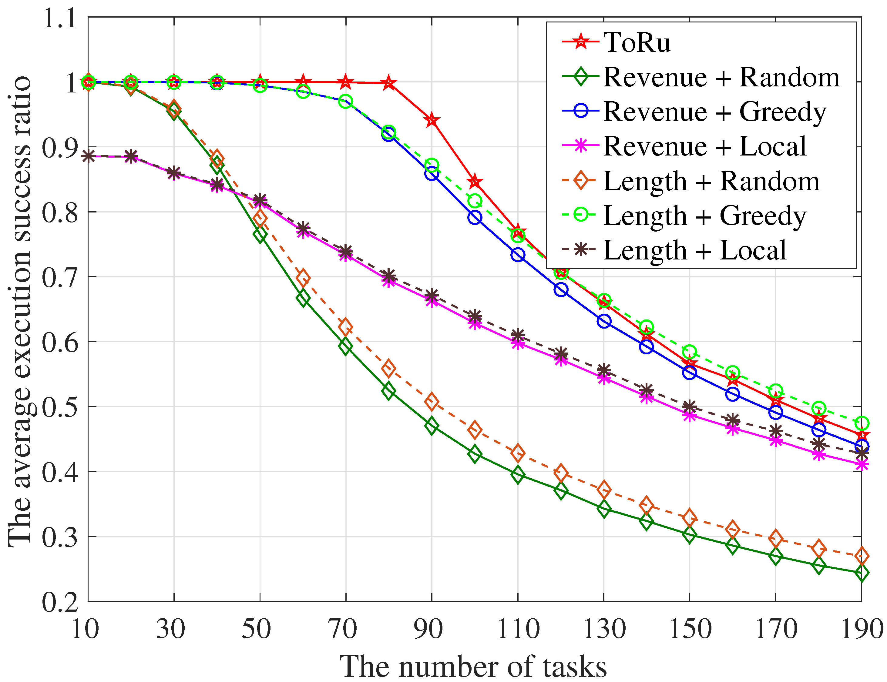
5.2.2. The Task Execution Success Ratio
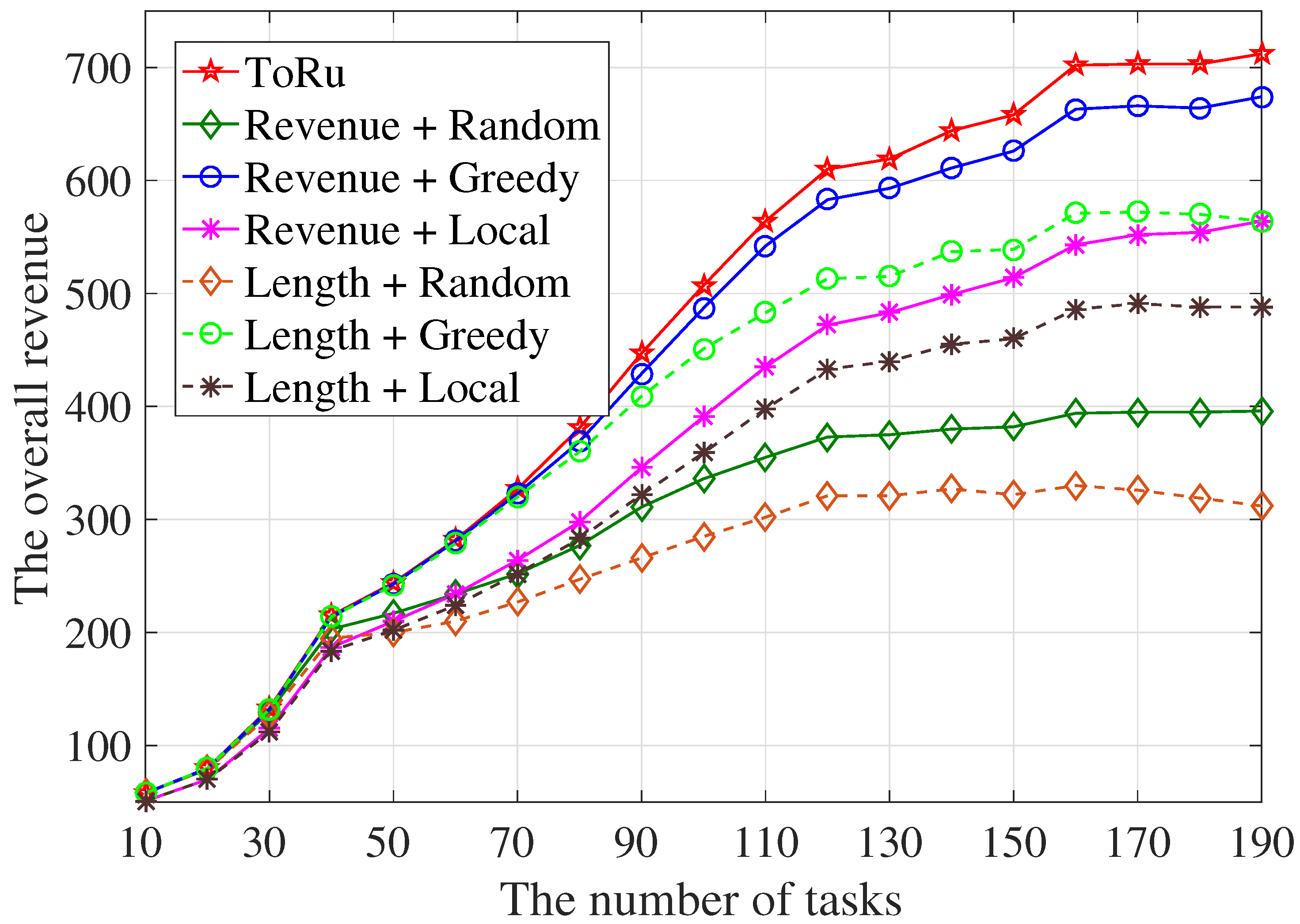
5.2.3. The Overall Revenue
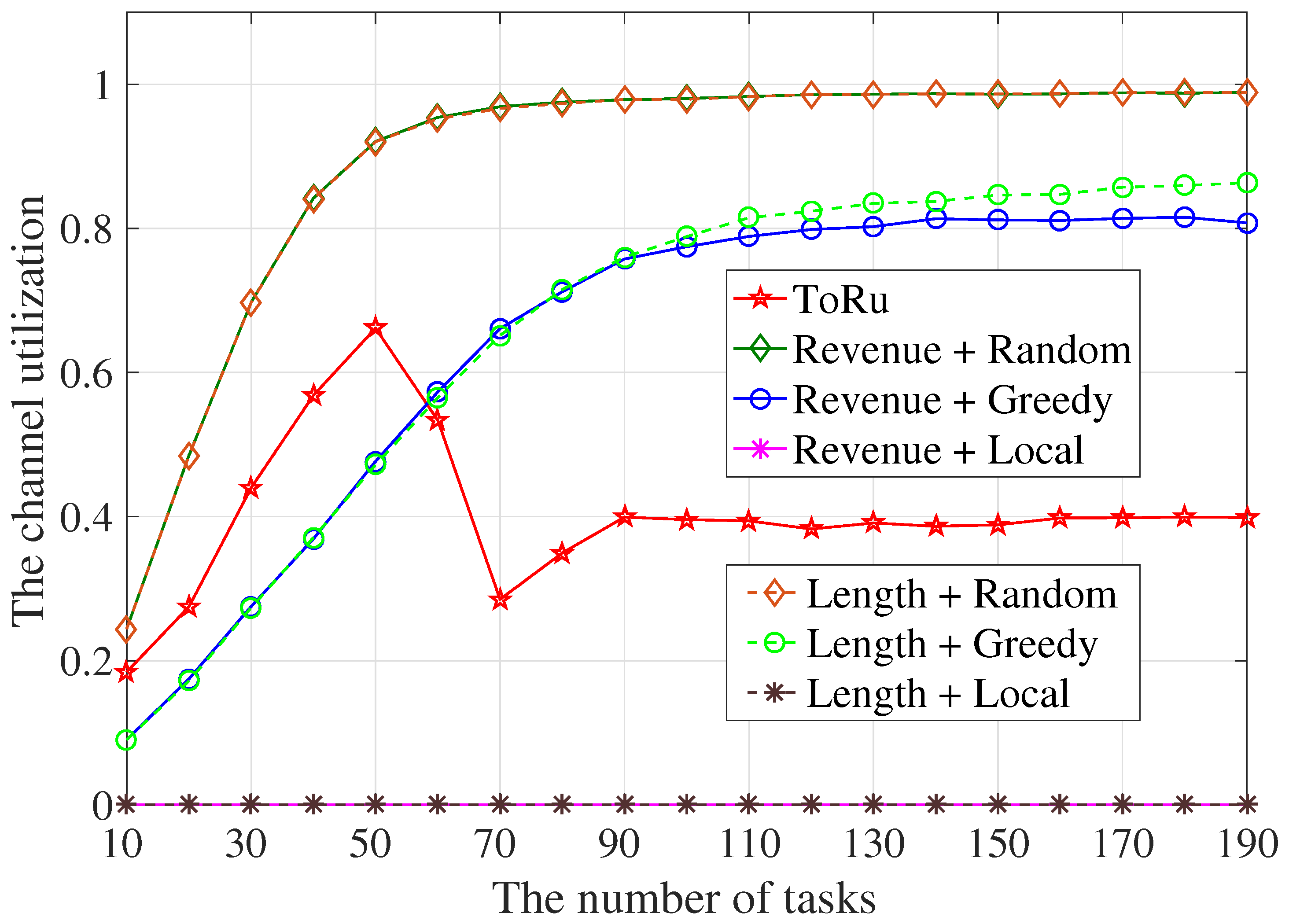
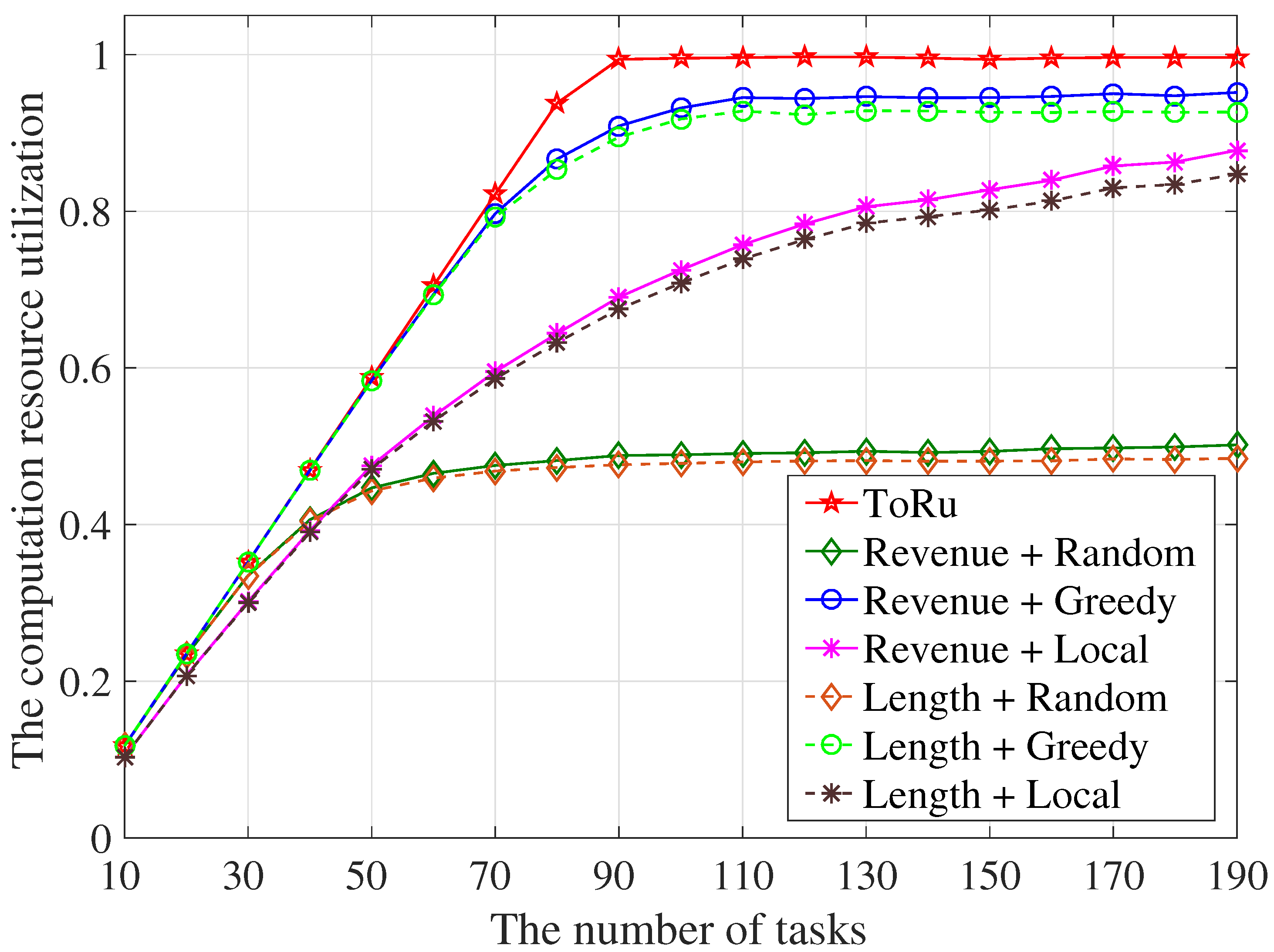
5.2.4. The Resources Utilization
5.2.5. The Operation Time
6. Conclusions
Author Contributions
Funding
Institutional Review Board Statement
Informed Consent Statement
Data Availability Statement
Acknowledgments
Conflicts of Interest
References
- Chen, W.; He, R.; Wang, G.; Zhang, J.; Wang, F.; Xiong, K.; Ai, B.; Zhong, Z. Ai assisted phy in future wireless systems: Recent developments and challenges. China Commun. 2021, 18, 285–297. [Google Scholar] [CrossRef]
- Sarikhani, R.; Keynia, F. Cooperative spectrum sensing meets machine learning: Deep reinforcement learning approach. IEEE Commun. Lett. 2020, 24, 1459–1462. [Google Scholar] [CrossRef]
- Zheng, S.; Chen, S.; Qi, P.; Zhou, H.; Yang, X. Spectrum sensing based on deep learning classification for cognitive radios. China Commun. 2020, 17, 138–148. [Google Scholar] [CrossRef]
- Xie, J.; Liu, C.; Liang, Y.-C.; Fang, J. Activity pattern aware spectrum sensing: A cnn-based deep learning approach. IEEE Commun. Lett. 2019, 23, 1025–1028. [Google Scholar] [CrossRef]
- Deng, S.; Zhao, H.; Fang, W.; Yin, J.; Dustdar, S.; Zomaya, A.Y. Edge intelligence: The confluence of edge computing and artificial intelligence. IEEE Internet Things J. 2020, 7, 7457–7469. [Google Scholar] [CrossRef]
- Wang, J.; Wei, X.; Fan, J.; Duan, Q.; Liu, J.; Wang, Y. Request pattern change-based cache pollution attack detection and defense in edge computing. Digit. Commun. Netw. 2022. [Google Scholar] [CrossRef]
- Liu, Z.; Cao, Y.; Gao, P.; Hua, X.; Zhang, D.; Jiang, T. Multi-uav network assisted intelligent edge computing: Challenges and opportunities. China Commun. 2022, 19, 258–278. [Google Scholar] [CrossRef]
- Wu, W.; Zhou, F.; Wang, B.; Wu, Q.; Dong, C.; Hu, R.Q. Unmanned Aerial Vehicle Swarm-Enabled Edge Computing: Potentials, Promising Technologies, and Challenges. IEEE Wirel. Commun. 2022, 29, 78–85. [Google Scholar] [CrossRef]
- Zhao, N.; Lu, W.; Sheng, M.; Chen, Y.; Tang, J.; Yu, F.R.; Wong, K.K. Uav-assisted emergency networks in disasters. IEEE Wirel. Commun. 2019, 26, 45–51. [Google Scholar] [CrossRef]
- Cao, B.; Li, M.; Liu, X.; Zhao, J.; Cao, W.; Lv, Z. Many-Objective Deployment Optimization for a Drone-Assisted Camera Network. IEEE Trans. Netw. Sci. Eng. 2021, 8, 2756–2764. [Google Scholar] [CrossRef]
- Wang, X.; Han, Y.; Leung, V.C.M.; Niyato, D.; Yan, X.; Chen, X. Convergence of edge computing and deep learning: A comprehensive survey. IEEE Commun. Surv. Tutor. 2020, 22, 869–904. [Google Scholar] [CrossRef]
- Dong, C.; Shen, Y.; Qu, Y.; Wang, K.; Zheng, J.; Wu, Q.; Wu, F. Uavs as an intelligent service: Boosting edge intelligence for air-ground integrated networks. IEEE Netw. 2021, 35, 167–175. [Google Scholar] [CrossRef]
- Behravesh, R.; Harutyunyan, D.; Coronado, E.; Riggio, R. Time-sensitive mobile user association and sfc placement in mec-enabled 5g networks. IEEE Trans. Netw. Serv. Manag. 2021, 18, 3006–3020. [Google Scholar] [CrossRef]
- Xu, Z.; Gong, W.; Xia, Q.; Liang, W.; Rana, O.F.; Wu, G. Nfv-enabled iot service provisioning in mobile edge clouds. IEEE Trans. Mob. Comput. 2021, 20, 1892–1906. [Google Scholar] [CrossRef]
- Wang, Y.; Wei, X.; Wang, H.; Fan, J.; Chen, J.; Zhao, K.; Hu, Y. Joint UAV deployment, SF placement, and collaborative task scheduling in heterogeneous multi-UAV-empowered edge intelligence. IET Commun. Early Access Artic. 2023. [Google Scholar] [CrossRef]
- Xu, C.; Jiang, S.; Luo, G.; Sun, G.; An, N.; Huang, G.; Liu, X. The case for fpga-based edge computing. IEEE Trans. Mob. Comput. 2022, 21, 2610–2619. [Google Scholar] [CrossRef]
- Li, J.; Un, K.-F.; Yu, W.-H.; Mak, P.-I.; Martins, R.P. An fpga-based energy-efficient reconfigurable convolutional neural network accelerator for object recognition applications. IEEE Trans. Circuits Syst. Express Briefs 2021, 68, 3143–3147. [Google Scholar] [CrossRef]
- Yu, X.; Niu, W.; Zhu, Y.; Zhu, H. UAV-assisted cooperative offloading energy efficiency system for mobile edge computing. Digit. Commun. Netw. 2022. [Google Scholar] [CrossRef]
- Zhang, J.; Zhou, L.; Zhou, F.; Seet, B.-C.; Zhang, H.; Cai, Z.; Wei, J. Computation-efficient offloading and trajectory scheduling for multi-uav assisted mobile edge computing. IEEE Trans. Veh. Technol. 2020, 69, 2114–2125. [Google Scholar] [CrossRef]
- Luo, Y.; Ding, W.; Zhang, B. Optimization of task scheduling and dynamic service strategy for multi-uav-enabled mobile-edge computing system. IEEE Trans. Cogn. Commun. Netw. 2021, 7, 970–984. [Google Scholar] [CrossRef]
- Wang, Y.; Ru, Z.-Y.; Wang, K.; Huang, P.-Q. Joint deployment and task scheduling optimization for large-scale mobile users in multi-uav-enabled mobile edge computing. IEEE Trans. Cybern. 2020, 50, 3984–3997. [Google Scholar] [CrossRef]
- Chang, H.; Chen, Y.; Zhang, B.; Doermann, D. Multi-uav mobile edge computing and path planning platform based on reinforcement learning. IEEE Trans. Emerg. Top. Comput. Intell. 2022, 6, 489–498. [Google Scholar] [CrossRef]
- Ren, T.; Niu, J.; Dai, B.; Liu, X.; Hu, Z.; Xu, M.; Guizani, M. Enabling efficient scheduling in large-scale uav-assisted mobile-edge computing via hierarchical reinforcement learning. IEEE Internet Things J. 2022, 9, 7095–7109. [Google Scholar] [CrossRef]
- Xue, J.; Wu, Q.; Zhang, H. Cost optimization of UAV-MEC network calculation offloading: A multi-agent reinforcement learning method. Ad Hoc Netw. 2022, 136, 102981. [Google Scholar] [CrossRef]
- Seid, A.M.; Boateng, G.O.; Mareri, B.; Sun, G.; Jiang, W. Multi-Agent DRL for Task Offloading and Resource Allocation in Multi-UAV Enabled IoT Edge Network. IEEE Trans. Netw. Serv. Manag. 2021, 18, 4531–4547. [Google Scholar] [CrossRef]
- Wu, Z.; Yang, Z.; Yang, C.; Lin, J.; Liu, Y.; Chen, X. Joint deployment and trajectory optimization in UAV-assisted vehicular edge computing networks. J. Commun. Netw. 2022, 24, 47–58. [Google Scholar] [CrossRef]
- Moura, J.; Hutchison, D. Game Theory for Multi-Access Edge Computing: Survey, Use Cases, and Future Trends. IEEE Commun. Surv. Tutor. 2019, 2, 260–288. [Google Scholar] [CrossRef]
- Liu, L.; Zhang, S.; Zhang, L.; Pan, G.; Yu, J. Multi-UUV Maneuvering Counter-Game for Dynamic Target Scenario Based on Fractional-Order Recurrent Neural Network. IEEE Trans. Cybern. Access Artic. 2022. [Google Scholar] [CrossRef]
- Asheralieva, A.; Niyato, D. Hierarchical game-theoretic and reinforcement learning framework for computational offloading in uav-enabled mobile edge computing networks with multiple service providers. IEEE Internet Things J. 2019, 6, 8753–8769. [Google Scholar] [CrossRef]
- Wu, Q.; Chen, J.; Xu, Y.; Qi, N.; Fang, T.; Sun, Y.; Jia, L. Joint Computation Offloading, Role, and Location Selection in Hierarchical Multicoalition UAV MEC Networks: A Stackelberg Game Learning Approach. IEEE Internet Things J. 2022, 9, 18293–18304. [Google Scholar] [CrossRef]
- Zhou, H.; Wang, Z.; Min, G.; Zhang, H. UAV-aided Computation Offloading in Mobile Edge Computing Networks: A Stackelberg Game Approach. IEEE Internet Things J. Early Access Artic. 2022. [Google Scholar] [CrossRef]
- Qu, Y.; Dai, H.; Wang, H.; Dong, C.; Wu, F.; Guo, S.; Wu, Q. Service provisioning for uav-enabled mobile edge computing. IEEE J. Sel. Areas Commun. 2021, 39, 3287–3305. [Google Scholar] [CrossRef]
- Wang, G.; Zhou, S.; Zhang, S.; Niu, Z.; Shen, X. SFC-Based Service Provisioning for Reconfigurable Space-Air-Ground Integrated Networks. IEEE J. Sel. Areas Commun. 2020, 38, 1478–1489. [Google Scholar] [CrossRef]
- Li, J.; Shi, W.; Wu, H.; Zhang, S.; Shen, X. Cost-Aware Dynamic SFC Mapping and Scheduling in SDN/NFV-Enabled Space–Air–Ground-Integrated Networks for Internet of Vehicles. IEEE Internet Things J. 2022, 9, 5824–5838. [Google Scholar] [CrossRef]
- Xia, J.; Wang, P.; Li, B.; Fei, Z. Intelligent task offloading and collaborative computation in multi-UAV-enabled mobile edge computing. China Commun. 2022, 19, 244–256. [Google Scholar] [CrossRef]
- Liu, S.; Yang, T. Delay aware scheduling in uav-enabled ofdma mobile edge computing system. IET Commun. 2020, 14, 3203–3211. [Google Scholar] [CrossRef]
- Tan, G.; Shui, C.; Wang, Y.; Yu, X.; Yan, Y. Optimizing the linpack algorithm for large-scale pcie-based cpu-gpu heterogeneous systems. IEEE Trans. Parallel Distrib. Syst. 2021, 32, 2367–2380. [Google Scholar] [CrossRef]
- Kowsalya, T. Area and power efficient pipelined hybrid merged adders for customized deep learning framework for FPGA implementation. Microprocess. Microsyst. 2020, 72, 102906. [Google Scholar] [CrossRef]


| Notation | Definition |
|---|---|
| The n-th UAV in | |
| Service Function | |
| SF instances | |
| Service Function Chain | |
| The n-th SF | |
| The set of FPGA-independent SFs | |
| The set of FPGA-dependent SFs | |
| The number of FPGA-independent SFs in | |
| The number of FPGA-dependent SFs in | |
| The set of SF deployed on | |
| The q-th SF deployed on | |
| The set of tasks currently requesting services | |
| The n-th requesting task | |
| The number of CPU cores on | |
| The number of FPGAs on | |
| The number of the current idle CPU cores on | |
| The number of the current idle FPGAs on | |
| The number of SIs currently created corresponding to | |
| The frequency of CPU core on | |
| The processing speed of CP when running SI of | |
| The wireless link of to | |
| The data transmission rate on one sub-channel of the link | |
| The number of current idle sub-channels on the link | |
| The source UAV that receives | |
| The required SFC of | |
| The k-th SF contained in the SFC required by | |
| The properties of before its entering into an SFC | |
| The properties of when arriving at the instance of in its SFC | |
| The length of when arriving at | |
| The number of CPU cycles required for processing one bit task on | |
| The number of AI accelerator operations required for processing one bit task on | |
| The minimum requirement set for the transmission rate between the instances of SFCs required by | |
| The minimum transmission rate requirement from the instance of to | |
| The minimum computation resources requirement set of for the instances of SFC. | |
| The minimum CPU processing speed requirement of on the instances of . | |
| The minimum AI accelerator processing speed requirement of on the instances of . | |
| The revenue obtained through completing | |
| The completion time of | |
| The decision variable of creating the instance of |
| Parameter | Value | Parameter | Value |
|---|---|---|---|
| M | 25 | Q | 30 |
| GHz | GOPS | ||
| 1 W | W/Hz | ||
| B | 1 MHz | ||
| 10 Mbit | 8 | ||
| Mbit | Cycles | ||
| OPs | |||
| 500 m |
| Number of Tasks | Operation Time | Number of Tasks | Operation Time |
|---|---|---|---|
| = 20 | ∼ 2 ms | = 110 | ∼ 34 ms |
| = 30 | ∼6 ms | = 120 | ∼36 ms |
| = 40 | ∼14 ms | = 130 | ∼38 ms |
| = 50 | ∼32 ms | = 140 | ∼40 ms |
| = 60 | ∼50 ms | = 150 | ∼46 ms |
| = 70 | ∼90 ms | = 160 | ∼50 ms |
| = 80 | ∼95 ms | = 170 | ∼56 ms |
| = 90 | ∼110 ms | = 180 | ∼62 ms |
| = 100 | ∼126 ms | = 190 | ∼74 ms |
Disclaimer/Publisher’s Note: The statements, opinions and data contained in all publications are solely those of the individual author(s) and contributor(s) and not of MDPI and/or the editor(s). MDPI and/or the editor(s) disclaim responsibility for any injury to people or property resulting from any ideas, methods, instructions or products referred to in the content. |
© 2023 by the authors. Licensee MDPI, Basel, Switzerland. This article is an open access article distributed under the terms and conditions of the Creative Commons Attribution (CC BY) license (https://creativecommons.org/licenses/by/4.0/).
Share and Cite
Wang, Y.; Wang, H.; Wei, X.; Zhao, K.; Fan, J.; Chen, J.; Hu, Y.; Jia, R. Service Function Chain Scheduling in Heterogeneous Multi-UAV Edge Computing. Drones 2023, 7, 132. https://doi.org/10.3390/drones7020132
Wang Y, Wang H, Wei X, Zhao K, Fan J, Chen J, Hu Y, Jia R. Service Function Chain Scheduling in Heterogeneous Multi-UAV Edge Computing. Drones. 2023; 7(2):132. https://doi.org/10.3390/drones7020132
Chicago/Turabian StyleWang, Yangang, Hai Wang, Xianglin Wei, Kuang Zhao, Jianhua Fan, Juan Chen, Yongyang Hu, and Runa Jia. 2023. "Service Function Chain Scheduling in Heterogeneous Multi-UAV Edge Computing" Drones 7, no. 2: 132. https://doi.org/10.3390/drones7020132