Article

Physical-Layer Security for UAV-Assisted Air-to-Underwater Communication Systems with Fixed-Gain Amplify-and-Forward Relaying

1
College of Information Science and Engineering, Harbin Institute of Technology (Weihai), Weihai 264209, China
2
College of Underwater Acoustic Engineering, Harbin Engineering University, Harbin 150001, China
3
School of Engineering, The University of British Columbia, Kelowna, BC V1Y 8L6, Canada
*
Author to whom correspondence should be addressed.
Drones 2022, 6(11), 341; https://doi.org/10.3390/drones6110341
Submission received: 17 October 2022 / Revised: 28 October 2022 / Accepted: 28 October 2022 / Published: 3 November 2022
(This article belongs to the Special Issue UAV-Assisted Intelligent Vehicular Networks)

Abstract

:
We analyze a secure unmanned aerial vehicle-assisted two-hop mixed radio frequency (RF) and underwater wireless optical communication (UWOC) system using a fixed-gain amplify-and-forward (AF) relay. The UWOC channel was modeled using a mixture exponential-generalized Gamma distribution to consider the combined effects of air bubbles and temperature gradients on transmission characteristics. Both legitimate and eavesdropping RF channels were modeled using flexible α - μ distributions. Specifically, we first derived both the probability density function (PDF) and cumulative distribution function (CDF) of the received signal-to-noise ratio of the system. Based on the PDF and CDF expressions, we derived the closed-form expressions for the tight lower bound of the secrecy outage probability (SOP) and the probability of non-zero secrecy capacity (PNZ), which are both expressed in terms bivariate Fox’s H-function. To utilize these analytical expressions, we derived asymptotic expressions of SOP and PNZ using only well-known functions. We also used asymptotic expressions to determine the suboptimal transmitting power to maximize energy efficiency. Furthermore, we investigated the effect of levels of air bubbles and temperature gradients in the UWOC channel, and studied the nonlinear characteristics of the transmission medium and the number of multipath clusters of the RF channel on the secrecy performance. Finally, all analyses were validated using a simulation.

1. Introduction

The rise of the underwater Internet of Things requires the support of a high-performance underwater communication network having high data rates, low latency, and long communication range. Underwater wireless optical communication (UWOC) is one of the essential technologies for this communication network. Unlike radio frequency (RF) [1,2,3] and acoustic technologies, UWOC technology can achieve ultra-high data rates of Gpbs over a moderate communication range when selecting blue or green light with wavelengths located in the transmission window [4]. Furthermore, a light-emitting diode or laser diode as a light source provides the versatility to select between communication range and coverage area within the constraints of the range-beamwidth tradeoff to meet the needs of a specific application scenario.
Using relay technology to construct a communication system in a multi-hop fashion is one of the primary techniques to extend the communication range. Based on the modality of processing and forwarding signals, relays can be divided into two main categories: decode-and-forward relays (DF) and amplify-and-forward (AF) relays. In DF relaying systems, the relay down-converts the received signals to the baseband, decodes, re-encodes, and up-converts them to the RF band, and forwards the signal to the destination node. In AF relaying systems, the relay amplifies the received signals directly in the passband based on an amplification factor, then forwards them directly in the RF band. Since the AF scheme does not require time-consuming decoding and spectral shifting, it can significantly reduce complexity while still providing good performance [5]. Depending on the different channel state information (CSI) information required by the AF relay, AF relaying can be divided into the variable-gain AF (VG) and fixed-gain AF (FG). In a VG scheme, the relay requires instantaneous CSI of the source-to-relay link, whereas in an FG scheme, only statistical CSI of the SR link is required [6]. Therefore, from an engineering standpoint, the FG scheme is more attractive because of its low implementation complexity.
To maximize the utilization of the different transmission environments of each hop and to improve the overall performance of the multi-hop relaying system, mixed communication systems using different communication technologies have been proposed, and are widely used in unmanned aerial vehicles (UAV)-assisted vehicle communication systems [7,8,9]. For example, the mixed communication system using both RF and free-space optical (FSO) technologies has been proposed to take advantage of the robustness of the RF links and the high bandwidth characteristics of the FSO links. Further, RF sub-systems offer low-cost and non-line-of-sight communication capabilities, while FSO sub-systems offer low transmission latency and ultra-high transmission rates. Therefore, a mixed RF/FSO system is a cost-effective solution to the last-mile problem in wireless communication networks, where the high-bandwidth FSO sub-system of a mixed RF/FSO system is used to connect seamlessly the fiber backbone and RF sub-system access networks [10,11,12,13]. Achieving ultra-high-speed communication between underwater and airborne nodes across the sea surface medium is challenging due to the low data rate of underwater acoustic communications. To solve this problem, using an ocean buoy or a marine ship as a relay node, the mixed RF/UWOC system for UAV and autonomous underwater vehicle (AUV) communication is proposed, in which the high-speed UWOC is used instead of underwater acoustic communication, to achieve higher overall communication rates [14,15,16,17,18].
Accurate modeling of the UWOC channel, including absorption, scattering, and turbulence, is a prerequisite for proper performance analysis and algorithm development of the UWOC system [19,20]. Absorption and scattering have been extensively studied [21,22,23], where absorption limits the transmission distance of underwater light, while scattering diffuses the receiving radius of underwater light transmission and deflects the transmission path, thus reducing the received optical power. Due to changes in the random refractive index variation, turbulence can cause fluctuations in the received irradiance, i.e., scintillation, which can limit the performance and affect the stability of the UWOC system [4]. In early research, UWOC turbulence was modeled by borrowing models of atmospheric turbulence, e.g., weak turbulence is modeled by the Lognormal distribution [24,25,26], and moderate-to-strong turbulence is modeled by the Gamma-Gamma distribution [27,28,29,30].
However, the statistical distributions used to model atmospheric turbulence cannot accurately characterize UWOC systems due to the fundamental differences between aqueous and atmospheric mediums. Recently, based on experimental data, the mixed exponential-lognormal distribution has been proposed to model moderate to strong UWOC turbulence in the presence of air bubbles in both fresh water and salty water [31]. Later, the mixture exponential-generalized Gamma (EGG) distribution was proposed to model turbulence in the presence of air bubbles and temperature gradients in either fresh or salt water [32]. The EGG distribution not only can model turbulence of various intensities, but also has an analytically tractable mathematical form. Therefore, useful system performance metrics, such as ergodic capacity, outage probability, and bit-error rate (BER), can be easily obtained.
Due to the broadcast nature of RF signals, secrecy performance has always been one of the most important considerations for the mixed RF/FSO communication systems [11,33,34,35,36,37]. In [34], the expressions of the lower bound of the secrecy outage probability (SOP) and average secrecy capacity (ASC) for mixed RF/FSO systems using VG or FG relaying schemes, were both derived in closed-form, where the RF and FSO links are modeled by the Nakagami-m and GG distributions, respectively. The authors in [35] used Rayleigh and GG distributions to model RF and FSO links, respectively. Considering the impact of imperfect channel state information (CSI), both the exact and asymptotic expressions of the lower bound for SOP of a mixed RF/FSO system using VG or FG relay are derived. The same authors then extended the analysis to multiple-input and multiple-output configuration and analyzed the impact of different transmit antenna selection schemes on the secrecy performance of the mixed RF/FSO system using a DF relay, where RF and FSO links are modeled by the Nakagami-m and M -distributions, respectively. Assuming the CSI of the FSO and RF links are imprecise and outdated, the authors derived the bound and asymptotic expressions of the effective secrecy throughput of the system. In [36], using more generalized η - μ and M -distributions to model RF and FSO links, respectively, and assuming that the eavesdropper is only at the relay location, the authors derived the analytical results for the SOP and the average secrecy rate of the mixed RF/FSO system using the FG or VG relaying scheme. To quantify the impact of the energy harvesting operation on the system secrecy performance, the authors in [11] derived exact closed-form and asymptotic expressions for the SOP of the downlink simultaneous wireless information and power transfer system using DF relaying scheme, under the assumption that RF and FSO links are modeled using the Nakagami-m and GG distributions, respectively.
However, research on the secrecy performance of mixed RF/UWOC systems is still in its infancy despite the growing number of underwater communication applications. The authors in [16] investigated the secrecy performance of a two-hop mixed RF/UWOC system using a VG or FG multiple-antennas relay and maximal ratio combining scheme, where RF and UWOC links are modeled by Nakagami-m and the mixed exponential-Gamma (EG) distributions, respectively. Assuming that only the source-to-relay link is eavesdropped by unauthorized users, the authors in [16] derived the exact closed expressions of the ASC and SOP of the mixed RF/UWOC systems. Later, based on the same channel model as in [16], the same authors extended the analysis to the mixed RF/UWOC system using a multi-antennas DF relay with the selection combining scheme [15]. Both the exact closed-form and asymptotic expressions of the SOP were derived.
However, while the EG distribution is suitable for modeling turbulence of various intensities in both fresh water and salty water, this distribution fails to model the effects of air bubbles and temperature gradients on UWOC turbulence [32]. Further, the Nakagami-m distribution is only applicable to certain specific scenarios and cannot accurately characterize the effects of the properties of the transmission medium and multipath clusters on channel fading. It is shown that the impact of the medium on the signal propagation is mainly determined by the nonlinearity characteristics of the medium [38]. The α - μ distribution is a more general, flexible, and mathematically tractable model of channel fading whose parameters α and μ are correlated with the nonlinearity of the propagation medium and the number of clusters of multipath transmission, respectively. Further, by setting α and μ to specific values, the α - μ distribution can be reduced to several classical channel fading models, including Nakagami-m, Gamma, one-sided Gaussian, Rayleigh, and Weibull distributions. Recently, the secrecy performance of a two-hop mixed RF/UWOC system using DF relaying where RF and UWOC links are, respectively, modeled by flexible α - μ and water tank experimental data based EGG distributions has been analyzed in [39]; however, only the lower bound and asymptotic expressions of the SOP are derived. Furthermore, the overall end-to-end latency of the DF relaying based mixed RF/UWOC communication system is much higher than that of the FG relaying based one, due to the decoding and forwarding and spectral shifting operations required by DF relaying.
However, to the best of the authors’ knowledge, this is the first comprehensive secrecy performance analysis of the mixed RF/UWOC communications system using a low-complexity FG relaying scheme. Unlike previous UWOC channel models that do not adequately characterize the underwater optical propagation and RF channel models that use various simplifying assumptions, we model the RF channels between UAV and relay and the UWOC channel between relay and AUV, using the more general and accurate α - μ and EGG distributions, respectively, to analyze the effects of a variety of realistic channel phenomena, such as different temperature gradients and levels of air bubbles of UWOC channels and different grades of medium nonlinearity, and the number of multipath clusters of the RF channels on the secrecy performance of the mixed RF/UWOC communication systems. We propose a novel analytical framework to derive the closed-form expressions of the SOP and the non-zero secrecy capacity (PNZ) metrics by the bivariate Fox’s H-function. Moreover, our secrecy performance study provides a generalized framework for several fading models for both RF and UWOC channels, such as Rayleigh, Weibull for RF channels and EG and Generalized Gamma for UWOC channels. We first derive the probability density function (PDF) and cumulative distribution function (CDF) of the end-to-end signal-to-noise ratio (SNR) for the mixed RF/UWOC communication system in exact closed-form in terms of bivariate H-function. Depending on these expressions, we derive the exact closed-form expressions of the lower bound of the SOP and the PNZ. Furthermore, we also derive asymptotic expressions for both SOP and PNZ containing only simple functions at high SNRs. Addtionally, based on the asymptotic expressions for SOP and PNZ, we provide a straightforward approach to determine the suboptimal source transmission power to maximize energy efficiency for given performance goals of both SOP and PNZ. Finally, we use Monte Carlo simulation to validate all the derived analytical expressions and theoretical analyses.
The rest of this paper is organized as follows. In Section 2, the channel and system models are presented. In Section 3, the end-to-end statistics are studied. Both exact and asymptotic expressions for the SOP and PNZ are derived in Section 4. The numerical results and discussions are discussed in Section 5, which is followed by the conclusion in Section 6.

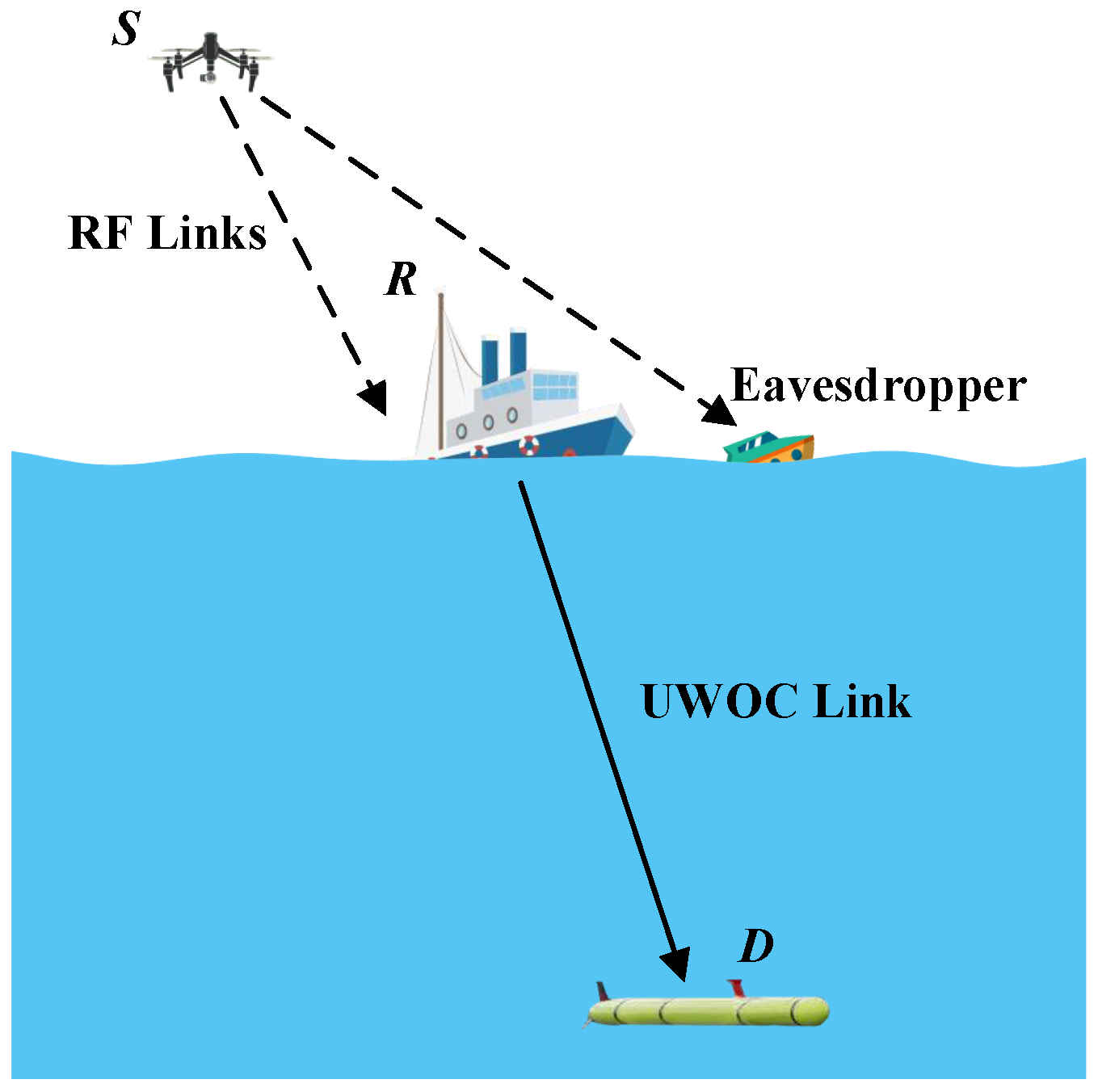
2. System and Channel Models

A mixed RF/UWOC system is considered in Figure 1 where a UAV acts as a source node (S) in the air transmits its private data to the legitimate destination node (D) acted by an AUV located underwater via a trusted relay node (R), which can be a buoy or a surface ship. The RF channel from S to R and underwater optical channel from the R to the D node is assumed to follow α - μ and EGG distributions, respectively. During transmission, one unauthorized receiver (E) attempts to eavesdrop on RF signals received by the R. In this paper, we consider a FG AF relay where the relay amplifies the received signal by a fixed factor and then forwards the amplified message to the destination node.

2.1. RF Channel Model

The RF SR link is modeled by α - μ flat fading models, where the PDF of the received SNR, denoted by γ 1 , can be expressed as [38]
f γ 1 γ 1 = α 2 Γ ( μ ) μ μ γ ¯ 1 α μ 2 γ 1 α μ 2 1 exp μ γ 1 γ ¯ 1 α 2
where γ 1 0 , μ 0 , α 0 , and Γ ( · ) denotes the gamma function. The fading model parameters α and μ are associated with the non-linearity and multi-path propagation of the channel. Furthermore, the PDF of the received SNR at the eavesdropping node E, denoted by f γ e ( γ e ) , also follows α - μ with parameters α e and μ e .
Based on the definition of the Fox’s H-function, the CDF of γ 1 , which is defined as F γ 1 ( γ 1 ) = 0 γ 1 f γ 1 ( γ 1 ) d γ 1 , can be expressed as
F γ 1 γ 1 = ( a ) κ 0 γ H 0 , 1 1 , 0 γ Λ 1 α + μ , 1 α d γ = i κ 2 π L s Λ s Γ s α + μ 1 α 0 γ γ s d γ d s = κ Λ H 1 , 2 1 , 1 γ Λ ( 1 , 1 ) μ , 1 α , ( 0 , 1 )
where we use ([40], Equation (1.60)) and ([40], Equation (1.125)) to express f γ 1 ( γ 1 ) in the right side of equity (a) into the form of H-function, where H · , · · , · [ · | · ] is the H-Function ([40], Equation (1.2)), κ = β Γ ( μ ) γ ¯ 1 , Λ = β γ ¯ 1 , and β = Γ 1 α + μ Γ ( μ ) . Note that, the present form of F γ 1 γ 1 in (2) is more suitable for deriving secrecy performance of a two-hop mixed RF/UWOC than the form proposed in ([41], Equation (2)) for the point-to-point system over single-input multiple-output α - μ channels.

2.2. UWOC Channel Model

To characterize the combined effects of different levels of air bubbles and temperature gradients on the light intensity received at underwater node D, we model the UWOC channel from R to D using the EGG distribution [32], where the PDF of the received SNR, defined as γ 2 = η I r / N 0 2 , has been derived in closed-form in terms of Meijer-G functions ([42], Equation (3)), and N 0 2 is the received noise power at D. Based on ([40], Equation (1.112)), we can re-write the PDF of γ 2 using H-functions as
f γ 2 ( γ 2 ) = c ( 1 ω ) γ r Γ ( a ) H 0 , 1 1 , 0 b c γ 2 μ r c r | ( a , 1 ) + ω γ 2 r H 0 , 1 1 , 0 1 λ γ 2 μ r 1 r | ( 1 , 1 )
where the parameters ω , a, b and c can be estimated using the maximum-likelihood criterion with expectation maximization algorithm. The parameter ω is the mixed weight of the distribution; λ is the parameter related to the exponential distribution; parameters a, b, and c are related to the exponential distribution; r is a parameter dependent on the detection scheme, specifically, r = 1 for heterodyne detection and r = 2 for intensity modulation and direct detection ([43], Equation (31)).
The EGG distribution can provide the best fit with the measured data form laboratory water tank experiments in the presence of temperature gradients and air bubbles [42]. Therefore, by using the EGG distribution to model the UWOC link, we can gain more insight into the relationship between characteristics of the UWOC link and the secrecy performance of the mixed RF/UWOC communication system.
Using the definition of complementary cumulative distribution function (CCDF), i.e., F ¯ γ 2 ( γ 2 ) = 0 γ 2 f γ 2 ( γ 2 ) d γ 2 , and an approach similar to that used to derive (2), we can derive the CCDF of γ 2 as
F ¯ γ 2 γ 2 = i ( 1 ω ) 2 π Γ ( a ) L s Γ a + r s c b r s μ r s γ 1 γ s + 1 d γ d s i ω 2 π L s Γ ( r s + 1 ) λ r s μ r s γ 1 γ s + 1 d γ d s = ( 1 ω ) Γ ( a ) H 1 , 2 2 , 0 b r γ μ r | ( 1 , 1 ) ( 0 , 1 ) , ( a , r c ) + r ω H 0 , 1 1 , 0 γ λ r μ r | ( 0 , r ) .
It is worth to mention that the expression in (4) is useful to derive the closed-form CDF expression of the end-to-end SNR of the mixed RF/UWOC communication system.

3. End-to-End SNR

In this section, we derive the exact closed-form expressions for PDF and CDF of the end-to-end SNR of mixed RF/UWOC communication system. We then use these expressions to derive closed-form and asymptotic expressions for the system secrecy metrics in the following section.
The end-to-end instantaneous SNR of the mixed RF/UWOC system using the FG relaying scheme is given as [6]
γ e q = γ 1 γ 2 γ 2 + C
where C denotes the FG amplifying constant and is inversely proportional to the square of the relay transmitting power, and this constant is defined as C = 1 / G 2 N 0 1 , where N 0 1 is the received noise power at R, and the FG amplifying factor G is defined as G = 1 / E N 0 γ 1 + 1 .
Using the definition of H-function and (1), we can readily express G 2 in terms of the H-functions
G 2 = κ H 1 , 2 2 , 1 Λ ( 0 , 1 ) ( 0 , 1 ) , ( 1 α + μ , 1 α ) .
It is worth noting that the FG relaying requires only the statistical CSI of the RF channel from S to R, and is therefore more convenient than VG relaying, which requires the instantaneous CSI, from the perspective of practical system deployment.
Theorem 1.
The CDF of the end-to-end SNR of the mixed RF/UWOC communication system using the FG relaying scheme F γ e q ( γ e q ) , defined in (5), can be obtained in exact closed-form as
F γ e q ( γ e q ) = 1 γ κ ( 1 ω ) Γ ( a ) × H 1 , 0 : 0 , 2 ; 1 , 1 0 , 1 : 2 , 0 ; 0 , 1 b r C μ r 1 γ Λ | ( 2 , 1 , 1 ) : ; 1 + 1 α μ , 1 α : ( 0 , 1 ) , ( a , r c ) ; ( 1 , 1 ) H 1 , 0 : 0 , 2 ; 1 , 1 0 , 1 : 2 , 0 ; 0 , 1 C λ r μ r 1 γ Λ | ( 2 , 1 , 1 ) : ; 1 + 1 α μ , 1 α : ( 1 , 1 ) , ( 0 , r ) ; ( 1 , 1 ) × γ κ r ω
in terms of bivariate H-functions, where H · , · : · , · ; · , · · , · : · , · ; · , · [ · | · ] is the bivariate H-Function defined as ([40], Equation (2.55)).
Proof. 
See Appendix A. □
Note that the current implementation of bivariate H-function for numerical computation is mature and efficient, including GPU-accelerated versions, and has been implemented using the most popular software, including MATLAB ® [44], Mathematica ® [45], and Python [46]. Addtionally, the exact-closed expression for the CDF in (7) is a key analytical tool to derive the SOP metric of the mixed RF/UWOC system.
Theorem 2.
The PDF of the end-to-end SNR, which is defined in (5), of the mixed RF/UWOC communication system using the FG relaying scheme, denoted by f γ e q ( γ e q ) , can be obtained in exact closed-form as
f γ e q ( γ e q ) = κ ( 1 ω ) Γ ( a ) × H 1 , 0 : 1 , 1 ; 0 , 2 0 , 1 : 0 , 1 ; 2 , 0 1 γ Λ b r C μ r | ( 2 , 1 , 1 ) : 1 + 1 α μ , 1 α ; : ( 2 , 1 ) ; ( 0 , 1 ) , ( a , r c ) + H 1 , 0 : 1 , 1 ; 0 , 2 0 , 1 : 0 , 1 ; 2 , 0 1 γ Λ C λ r μ r | ( 2 , 1 , 1 ) : 1 + 1 α μ , 1 α ; : ( 2 , 1 ) ; ( 1 , 1 ) , ( 0 , r ) × κ r ω .
Proof. 
See Appendix B. □
It is worth noting that the PDF expression in (8) is the most critical step required to evaluate the PNZ performance metric, as will be shown in the next section.

4. Performance Metrics

His section presents analytical results for the critical secrecy performance metrics of a mixed RF/UWOC communication system, including both SOP and PNZ, in the presence of air bubbles and temperature gradients in the UWOC channel and medium nonlinearity in the RF channel.

4.1. SOP

SOP is defined as the probability that the secrecy capacity C s falls below a target rate of confidential information R s and it can be expressed as
P o u t R s = Pr log 2 1 + γ e q 1 + γ e < R s = 0 F e q Θ γ e + Θ 1 f e γ e d γ e
where Θ = e R s .

4.1.1. Lower Bound

Referring to [47,48], a tight lower bound for the SOP can be given as
P o u t , L = 0 F γ e q ( Θ γ ) f γ e ( γ ) d γ .
Theorem 3.
The lower bound for the SOP of the mixed RF/UWOC communication system using the FG relaying scheme defined in (10) can be obtained in exact closed-form as
P o u t , L = 1 Θ κ Λ e Γ ( μ e ) ( ( 1 ω ) Γ ( a ) × H 1 , 0 : 1 , 2 ; 0 , 2 0 , 1 : 1 , 1 ; 2 , 0 Λ e Θ Λ b r C μ r | ( 2 , 1 , 1 ) : 1 + 1 α μ , 1 α ; : 1 α e + μ e , 1 α e , ( 1 , 1 ) ; ( 0 , 1 ) , ( a , r c ) H 1 , 0 : 1 , 2 ; 0 , 2 0 , 1 : 1 , 1 ; 2 , 0 Λ e Θ Λ C λ r μ r | ( 2 , 1 , 1 ) : 1 + 1 α μ , 1 α : : 1 α e + μ e , 1 α e , ( 1 , 1 ) : ( 1 , 1 ) , ( 0 , r ) × r ω ) .
Proof. 
See Appendix C. □
Special case. When the RF channel follows Rayleigh fading (i.e., α = α e = 1 , μ = μ e = 1 ) and the thermally uniform UWOC channel (i.e., c = 1 ) use heterodyne detection (i.e., r = 1 ), using definition of bivariate H-functions and ([49], Equation (07.34.03.0397.01)), Equation (5) can be simplified into the following form
P o u t , L = κ κ e Λ Λ e + Θ Λ ( a ( ω 1 ) exp J b E a + 1 J b ω G 2 , 1 1 , 2 λ J | 0 , 1 1 ) + 1
where J = C Θ Λ μ r Λ e + Θ Λ , E i ( x ) and E n ( x ) both denote the exponential integral ([50], Equation (8.211.1)). We emphasize that the distribution in (12) contains only elementary functions and leads to straightforward secrecy performance evaluation of two-hop mixed RF/UWOC systems.

4.1.2. Asymptotic Results

To gain more insight into the SOP performance and the dependency between the link quality of both RF and UWOC channels, we now derive asymptotic expressions for SOP. We consider two scenarios, namely γ 1 and γ e .
Corollary 1.
For scenarios γ 1 and γ e , the asymptotic expressions of SOP of a mixed RF/UWOC communication system using FG relaying scheme can be given as
P o u t , a , 1 = 1 1 Γ ( μ ) Γ ( μ e ) ( ( 1 ω ) Γ ( a ) × H 3 , 2 1 , 3 b r Λ e μ r C Θ Λ | ( 1 , 1 ) , ( 1 a , r c ) , ( 1 μ , 1 α ) μ e , 1 α e , ( 0 , 1 ) r ω H 2 , 1 1 , 2 λ r Λ e μ r C Θ Λ | ( 1 , r ) , ( 1 μ , 1 α ) μ e , 1 α e )
and
P o u t , a , e = 1 α e Γ μ + α e μ e α Γ ( μ ) Γ μ e Γ α e μ e + 1 Λ e Θ Λ α e μ e × ( ( 1 ω ) Γ ( a ) H 2 , 1 1 , 2 b r μ r C | ( 1 , 1 ) , ( 1 a , r c ) α e μ e , 1 r ω H 2 , 1 1 , 2 λ r μ r C | ( 0 , 1 ) , ( 1 , r ) α e μ e , 1 )
in terms of H-functions, respectively.
Proof. 
See Appendix D. □
Note that in contrast to the closed expression of the lower bound of the SOP in (11) in terms of bivariate H-functions, which requires numerical evaluation of double line integrals, the asymptotic expressions in (13) and (14) only require the numerical calculation of single line integrals, thus reducing the complexity of the calculations. Furthermore, as shown in Section 5, for a target SOP performance, the asymptotic expressions in (13) and (14) can be used to determine rapidly the suboptimal transmitting power to maximize energy efficiency.
Special case. A two-hop mixed RF/UWOC communication system over Rayleigh RF links and a thermally uniform UWOC channel, we can further simplify the asymptotic expressions in (13) and (14) by setting c = 1 , α = α e = 1 , μ = μ e = 1 . For example, Equation (13) can be simplified into
P o u t , a , 1 = 1 λ Λ e μ r Γ ( μ ) Γ ( μ e ) ( a λ ( ω 1 ) Λ e μ r exp C Θ Λ b Λ e μ r × E a + 1 C Θ Λ b Λ e μ r C Θ Λ ω exp C Θ Λ λ Λ e μ r × E i C Θ Λ λ Λ e μ r ) + Λ Λ e κ ω κ e Λ Λ e

4.2. PNZ

PNZ is another critical metric for to evaluate the secrecy performance of a communication system, which is defined as Pr C s > 0 , where C s is the secrecy capacity. PNZ is generally related to channel conditions of all the channels in the mixed RF/UWOC systems. In this section, we derive the exact closed-form and asymptotic expressions for PNZ and analyze the relationship between channel parameters and PNZ performance.

4.2.1. Exact Results

According to [48], PNZ can be reformed as
P n z = Pr γ e q > γ e = 0 f e q γ e q F e γ e q d γ e q .
Theorem 4.
The exact PNZ of the mixed RF/UWOC communication system using the FG relaying scheme defined in (16) can be obtained in exact closed-form as
P n z = κ Γ ( a ) Λ e Γ μ e ( ( 1 ω ) × H 1 , 0 : 0 , 2 ; 1 , 2 0 , 1 : 2 , 0 ; 1 , 1 b r C μ r Λ e Λ | ( 2 , 1 , 1 ) : ; 1 + 1 α μ , 1 α : ( 0 , 1 ) , ( a , r c ) ; 1 α e + μ e , 1 α e , ( 1 , 1 ) + H 1 , 0 : 0 , 2 ; 1 , 2 0 , 1 : 2 , 0 ; 1 , 1 C λ r μ r Λ e Λ | ( 2 , 1 , 1 ) 1 + 1 α μ , 1 α ( 1 , 1 ) , ( 0 , r ) 1 α e + μ e , 1 α e , ( 1 , 1 ) × r ω Γ ( a ) )
Proof. 
See Appendix E. □
Special case. For a RF/UWOC system with Rayleigh and uniform temperature EGG distributions, using a similar approach to the derivation of (12), we can simplify (17) into
P n z = κ κ e λ Λ Λ e + Λ ( ω H exp H / λ E 1 H λ + λ a ( ω 1 ) exp H b E a + 1 H b ω )
where H = C Λ Λ e + Λ μ r .

4.2.2. Asymptotic Results

To gain more insight into the PNZ performance and the dependency between the link quality of both RF and UWOC channels, we now derive asymptotic expressions for PNZ. We consider two scenarios, namely γ 1 and γ e .
Corollary 2.
For scenarios γ 1 and γ e , the asymptotic expressions of PNZ of a mixed RF/UWOC communication system using the FG relaying scheme are given as
P n z , 1 = 1 Γ ( a ) Γ ( μ ) Γ μ e ( ( 1 ω ) × H 2 , 3 3 , 1 b r C Λ Λ e μ r | 1 μ e , 1 α e , ( 1 , 1 ) ( 0 , 1 ) , ( a , r c ) , ( μ , 1 α ) + r ω Γ ( a ) H 1 , 2 2 , 1 C λ r Λ Λ e μ r | 1 μ e , 1 α e ( 0 , r ) , ( μ , 1 α ) )
and
P n z , e = α e Λ e Λ α e μ e Γ μ + α e μ e α Γ ( a ) Γ ( μ ) Γ μ e Γ α e μ e + 1 ( ( 1 ω ) × H 2 , 1 1 , 2 b r μ r C | ( 1 , 1 ) , ( 1 a , r c ) α e μ e , 1 + r ω Γ ( a ) H 2 , 1 1 , 2 λ r μ r C | ( 0 , 1 ) , ( 1 , r ) α e μ e , 1 )
in terms of H-functions, respectively. 
Proof. 
Observing that the expressions for the lower bound of the SOP in (11) and exact PNZ in (15) have a similar structure; therefore, Equations (19) and (20) can be easily obtained using the same techniques as those used for deriving (13) and (14), and the proof is complete. □
Note that, similar to the asymptotic expressions of the SOP in (13) and (14), for a target PNZ performance, the asymptotic expressions of PNZ in (19) and (20) are also suitable for fast numerical calculations and are useful to determine the suboptimal transmitting power to maximize energy efficiency.

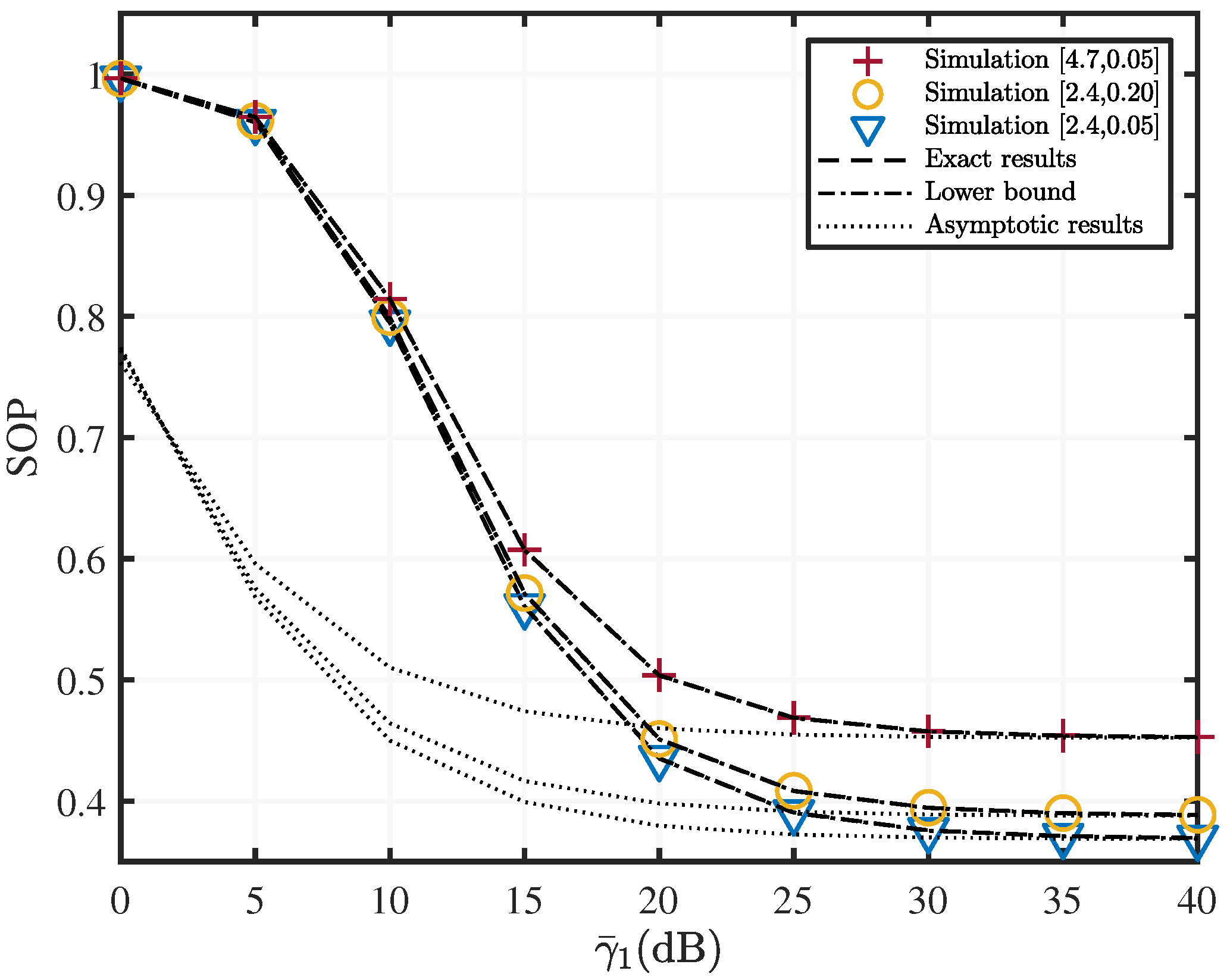
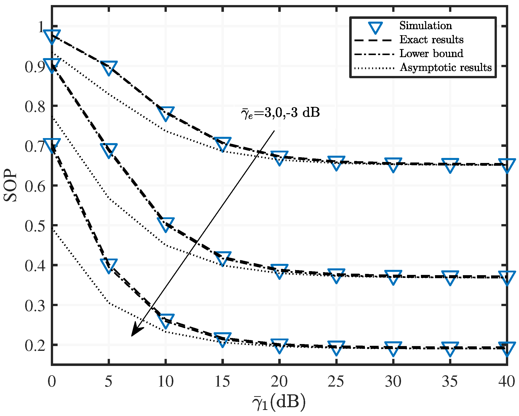
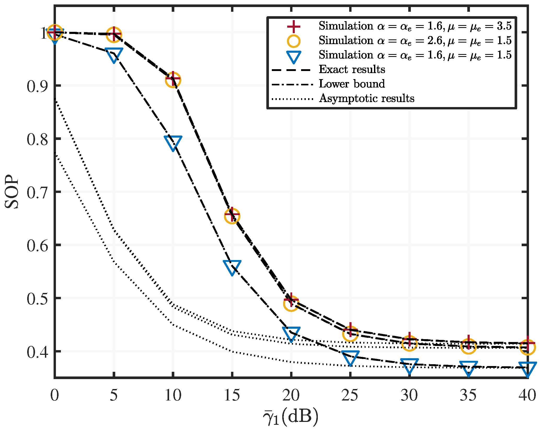
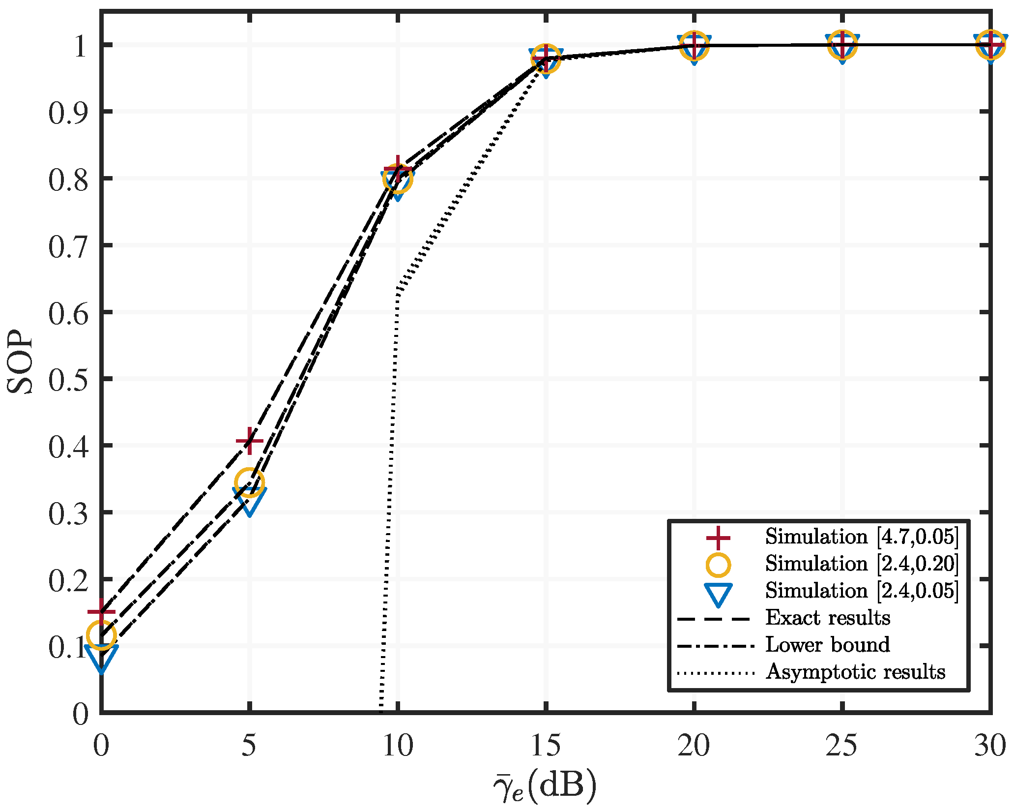
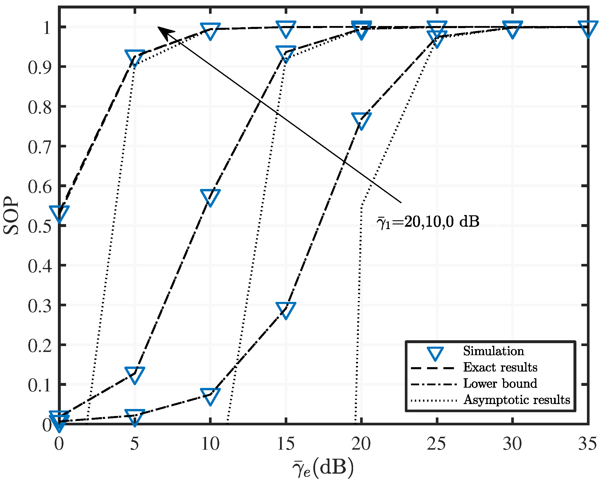
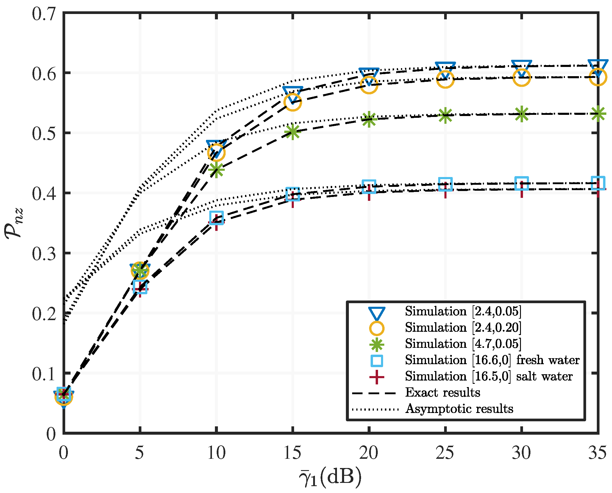
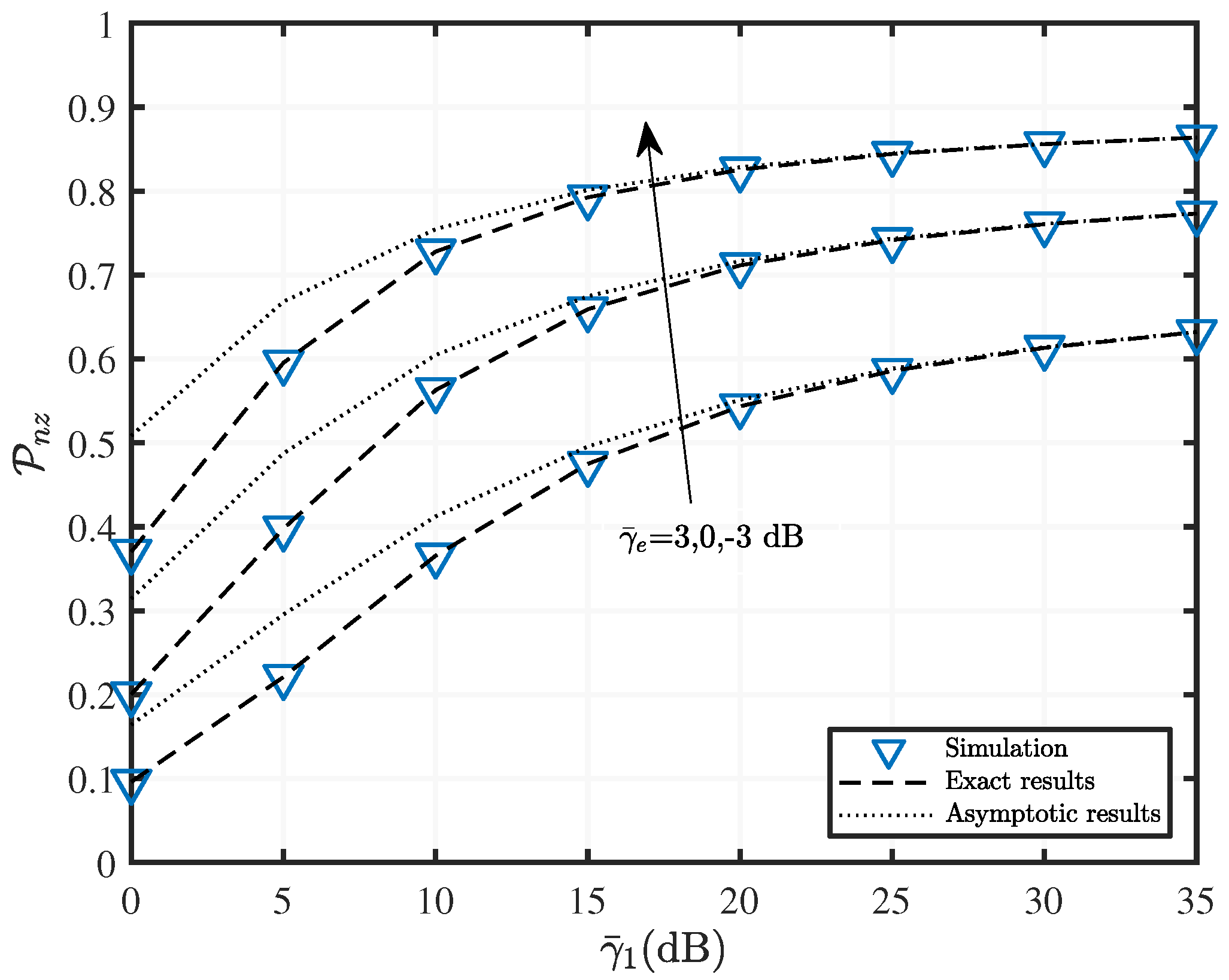
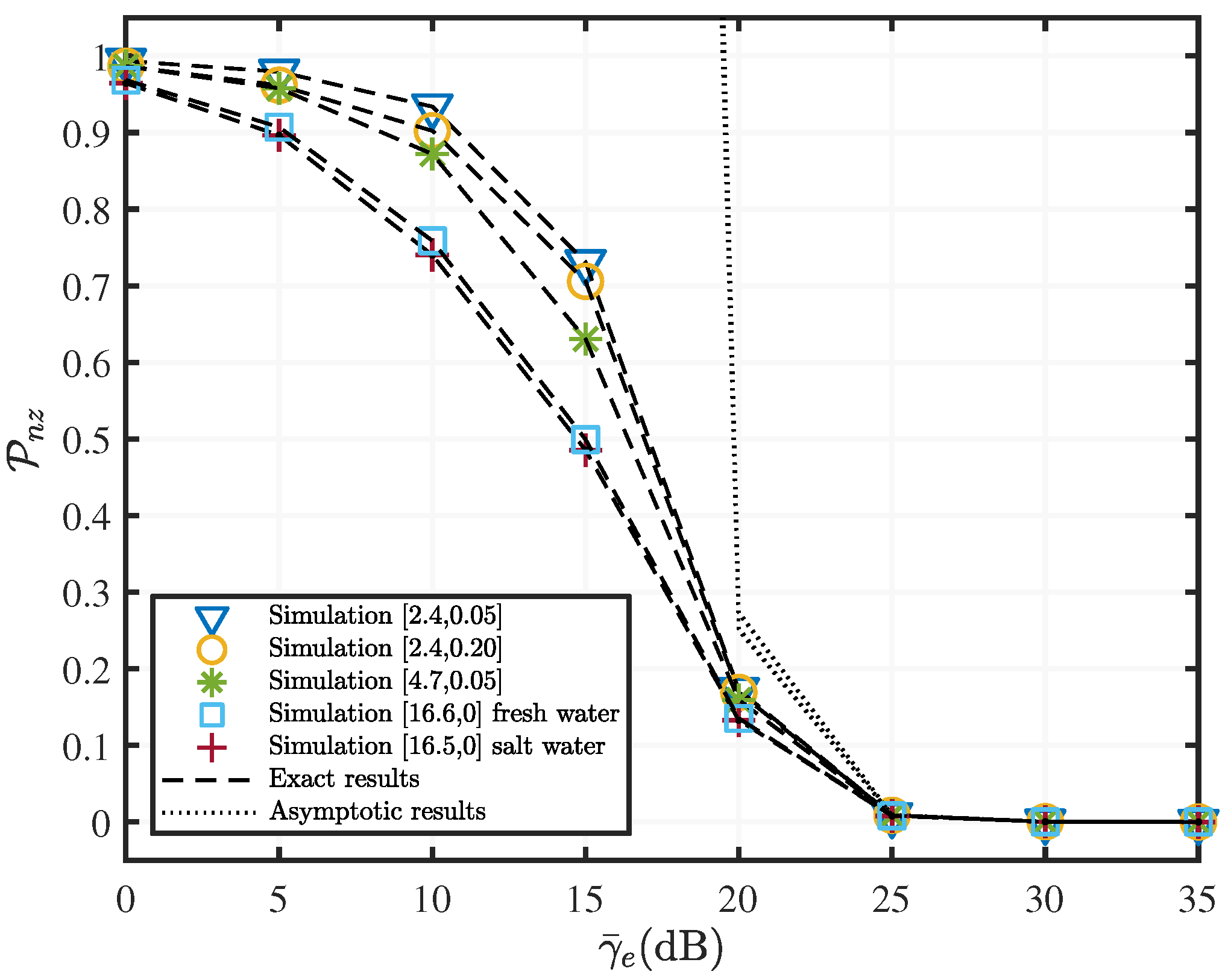
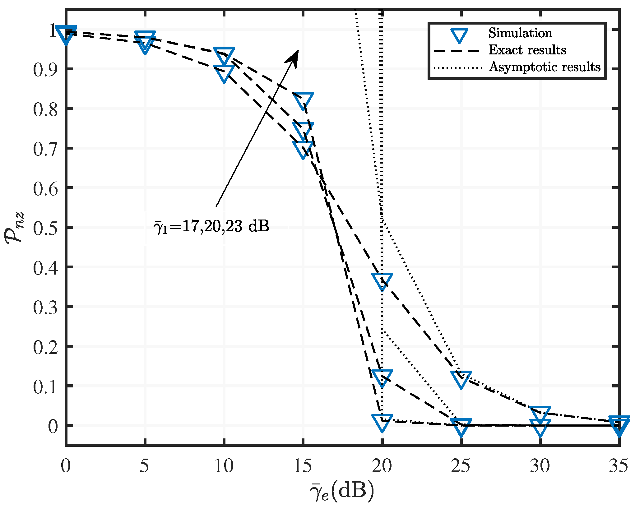
5. Numerical Results and Discussion

In this section, we provide some numerical results to verify the analytic and asymptotic expressions of SOP and PNZ derived in Section 4, and thoroughly investigate the combined effect of the channel quality of both RF and UWOC channels on the secrecy performance of the two-hop mixed RF/UWOC communication system. All practical environmental physical factors that can affect channel quality, including levels of air bubbles, temperature gradients, and salinity of the UWOC channel [32], as well as the medium nonlinearity and multipath cluster characteristics of the RF channel [48], are taken into account. For brevity, we use [ · , · ] to denote the value set of [ air bubbles level , temperature gradient ] in this section.
In Figure 2, Figure 3, Figure 4, Figure 5 and Figure 6, we investigate the combined effect of the channel quality of both RF and UWOC channels on the SOP metric of the two-hop mixed RF/UWOC communication system.
Figure 2. SOP versus γ ¯ 1 with various fading parameters when α = α e = 1.6 , μ = μ e = 1.5 , R s = 0.01 , and γ ¯ e = γ ¯ 2 = 10 dB.
Drones 06 00341 g002
Figure 2 shows the lower bound and the asymptotic SOP with average SNR of the SR link γ 1 for a mixed two-hop RF/UWOC system under different quality scenarios of UWOC channel. Both RF SR and SE links follow the α - μ distribution and have the same parameters, where α = α e = 1.6 , μ = μ e = 1.5 . The average SNR of the SE and RD links are both set as γ ¯ e = γ ¯ 2 = 10 dB [48]. As shown in Figure 2, the exact theoretical results are almost identical to the simulation results, and both closely agree with the derived lower bound. Asymptotic results are tight when the average SNR is greater than 30 dB. Further, when the average SNR increases from 0 to 30 dB, SOP rapidly decreases. Additionally, SOP tends to saturate when the average SNR is between 30 and 40 dB. Given the cost of the relay battery replacement and engineering difficulties, the communication system should guarantee the SOP while cutting down on energy consumption. In practice, one should therefore select the suboptimal transmission power corresponding to the saturation starting point.
Figure 3. SOP versus γ ¯ 1 with various fading parameters when α = α e = 1.6 , μ = μ e = 1.5 , R s = 0.01 , and γ ¯ 2 = 0 dB.
Drones 06 00341 g003
Figure 3 depicts the SOP variation versus the SR average SNR γ 1 for the mixed two-hop RF/UWOC system under three different eavesdropper interference levels, i.e., γ ¯ e = 3 , 0 , 3 dB. Parameters in Figure 3 are set as follows: α = α e = 1.6 , μ = μ e = 1.5 , UWOC channel parameter is [2.4, 0.05], and γ ¯ 2 = 0 dB. It can be observed that the lower bounds closely match the exact results in the whole SNR region. The asymptotic result curve gradually coincides with the exact result curve when γ ¯ 1 takes higher values starting from 20 dB. We can also observe that the SOP is monotonically decreasing with γ ¯ 1 , assuming that the SNR of the SE link is a fixed value. Comparing the SOP curves for three different eavesdropping interference levels, one can conclude that as the quality of the SE channel improves, the secrecy performance of the system deteriorates.
Figure 4. SOP versus γ ¯ 1 with various fading parameters R s = 0.01 , γ ¯ 2 = γ ¯ e = 10 dB, and UWOC channel parameter is [2.4, 0.05].
Drones 06 00341 g004
Figure 4 indicates the effect of the variation in average SNR of the SR link on the SOP metric of a two-hop mixed RF/UWOC, with three different RF channel qualities. Evidently, SOP monotonically decreases with the increase of γ ¯ 1 , and SOP tends to saturate when γ ¯ 1 30 dB. Moreover, Figure 4 depicts that as the α - μ value increases, the two-hop mixed RF/UWOC system secrecy performance worsens, and vice versa. This is because of the phenomena of severe nonlinearity and sparse clustering when the signals are propagating in a high α - μ value RF channel, and poor RF channel quality makes it easier for eavesdroppers to intercept signals. As shown in Figure 5, as the γ ¯ e progressively increases, the SOP value increases, the information intercepted by the eavesdropper increases, and the system secrecy performance gradually decreases. Moreover, the asymptotic result is more accurate at γ ¯ e greater than 15 dB.
Figure 5. SOP versus γ ¯ e with various fading parameters when α = α e = 1.6 , μ = μ e = 1.5 , R s = 0.01 , and γ ¯ 1 = γ ¯ 2 = 10 dB.
Drones 06 00341 g005
Figure 6. SOP versus γ ¯ e with various fading parameters when α = α e = 1.6 , μ = μ e = 1.5 , R s = 0.01 , and γ ¯ 2 = 20 dB.
Drones 06 00341 g006
In Figure 6, we set the same channel parameters as in Figure 3, except for setting the UWOC average SNR, i.e., γ ¯ 2 = 20 dB. Figure 6 shows that SOP increases with γ ¯ e when the other parameters remain unchanged. The same interpretation of Figure 5 can also be applied to Figure 6. Additionally, the rate at which the asymptotic results approach exact results varies for different SR average SNR. For γ ¯ 1 = 0 dB, the asymptotic results begin to match the exact result starting at γ ¯ e = 5 dB. Moreover, the close match of the lower bound and the exact results demonstrate the robustness and accuracy of (11).
In Figure 7, Figure 8, Figure 9 and Figure 10, We investigate the combined effect of the channel quality of both RF and UWOC channels on the PNZ metric of the two-hop mixed RF/UWOC communication system.
Figure 7 shows the effect of the SR link average SNR γ ¯ 1 on the PNZ of the mixed RF/UWOC for different UWOC channel parameters. PNZ increases incrementally as γ ¯ 1 increases, which indicates an increase in secrecy performance. It can be observed that PNZ decreases as the degree of turbulence increases, i.e., the higher the level of air bubbles and the larger the temperature gradient, the worse the secrecy performance in the system. Additionally, we depict the effects of salinity on UWOC performance in Figure 7. The salinity affects the system secrecy performance to a much lesser extent than the level of the air bubble and temperature gradient. This is because the generation and break-up of the air bubbles in the UWOC channels causes dramatic and random fluctuations of the underwater optical signals, which can significantly deteriorate the secrecy performance of the system. Figure 7 shows that eavesdroppers may benefit from a low UWOC channel quality. On the contrary, in a high-quality UWOC channel, the likelihood of an eavesdropper successfully eavesdropping is greatly reduced. Therefore, in practical applications, increasing the channel quality can increase the system transmission capacity and thus improve the system secrecy performance. Figure 7 also shows that asymptotic results can quickly approach the exact result for poorer channels. For example, for a UWOC channel with channel parameters of [16.5, 0], the asymptotic result can achieve a match with the exact value at γ ¯ 1 20 dB. When the channel parameter set is [2.4, 0.05], the asymptotic result can only be accurate at γ ¯ 1 > 25 dB. The remaining parameters are set as follows, γ ¯ e = γ ¯ 2 = 0 dB, α = α e = 2.1 , μ = μ e = 1.4 .
In Figure 8, the RF channel parameters are α = α e = 1.5 , μ = μ e = 0.8 , and the UWOC channel parameters are [2.4, 0.05]. We can explain the curves in Figure 8 using a principle similar to Figure 7. In particular, Figure 8 demonstrates the PNZ curves for three different SE link channel qualities. Obviously, as γ ¯ e decreases, the secrecy performance of the system improves.
In addition to Figure 8, we analyzed the effect of the average SNR γ ¯ 1 on the PNZ, as shown by Figure 9 and Figure 10. The difference is that in Figure 9 α = α e = 2.1 , μ = μ e = 1.4 and γ ¯ 1 = γ ¯ 2 = 20 dB. whereas the RF channel parameters in Figure 10 are α = α e = 1.5 and μ = μ e = 0.8 . It can be inferred from Figure 9 and Figure 10 that the asymptotic result only matches the exact value when γ ¯ e is large, and the PNZ gradually decreases until it reaches zero.

6. Conclusions

We investigated the secrecy performance of a UAV-assisted two-hop mixed RF/UWOC communication system using fixed-gain AF relaying. To allow the results to be more generic and applicable to more realistic physical scenarios, we modeled RF channels using the α - μ distribution, which considers both the nonlinear of the transmission medium and multipath cluster characteristics, and modeled UWOC channels using the laboratory EGG distribution, which can account for different levels of air bubbles, temperature gradients, and salinity. Closed-form expressions for the PDF and the CDF of the two-hop end-to-end SNR were both derived in terms of the bivariate H-function. Based on these results, we obtained a tight closed-form expression of the lower bound of the SOP and the exact closed-form expression of the PNZ. Furthermore, we also derived asymptotic expressions in simple functions for both SOP and PNZ to allow rapid numerical evaluation. Moreover, based on the asymptotic results, we presented an approach to determine the suboptimal transmitting power to maximize the energy efficiency, for given target performance of both SOP and PNZ. We fully investigated the effects of various existing phenomena of both RF and UWOC channels on the secrecy performance of the mixed RF/UWOC communication system. Additionally, our generalized theoretical framework is also applicable to various classical RF and underwater optical channel models including Rayleigh and Nakagami for RF channels and EG and Generalized Gamma for UWOC channels. Our results can be used in a practical mixed security RF/UWOC communication systems design. The interesting topics for future work include: (i) to investigate the secrecy performance of a mixed RF/UWOC communication system using an energy-harvesting enabled relay to improve the system lifetime; (ii) to investigate the secrecy performance of a mixed RF/UWOC communication system using multiple relays with appropriate relaying selection algorithms.

Author Contributions

Conceptualization, Y.L. and R.S.; methodology, Y.L.; software, J.W.; validation, Y.L., R.S. and J.C.; formal analysis, Y.L.; investigation, R.S.; resources, G.Q.; data curation, R.S.; writing—original draft preparation, Y.L.; writing—review and editing, J.C.; visualization, J.W.; supervision, G.Q.; project administration, G.Q.; funding acquisition, Y.L. All authors have read and agreed to the published version of the manuscript.

Funding

This research was funded by the National Natural Science Foundation of China (62101152).

Data Availability Statement

Not applicable.

Conflicts of Interest

The authors declare no conflict of interest.

Appendix A. Proof of Theorem 1

Using (5), we write the CDF of the end-to-end SNR in the following form
F γ e q ( γ e q ) = 0 Pr γ 1 γ 2 γ 2 + C γ γ 2 f γ 2 γ 2 d γ 2 = 1 γ F ¯ γ 2 C γ x γ f γ 1 ( x ) d x .
Substituting (1) and (4) into (A1) and replacing the integral variable x with z = x + γ , after some simplifications, we can express (A1) as
F γ e q γ e q = 1 + I 1 + I 2
where
I 1 = κ ( 1 ω ) Γ ( a ) 0 H 0 , 1 1 , 0 ( z + γ ) Λ 1 α + μ , 1 α × H 1 , 2 2 , 0 b r C γ z μ r | ( 1 , 1 ) ( 0 , 1 ) , ( a , r c ) d z
and
I 2 = κ r ω 0 H 0 , 1 1 , 0 C γ λ r z μ r | ( 0 , r ) × H 0 , 1 1 , 0 ( z + γ ) Λ 1 α + μ , 1 α d z .
To solve (A3), we convert all the H-functions in (A3) into a line integral, and place the integral with respect to x in the innermost part by rearranging the order of multiple integrals. Then, we have
I 1 = κ ( 1 ω ) 4 π 2 Γ ( a ) L t Γ ( t ) Γ ( t + 1 ) Γ a + r t c b r μ r C γ t × L s Λ s Γ s α + μ 1 α 0 z t ( z + γ ) s d z d s d t .
By utilizing ([50], Equation (3.197/1)) to solve the integration of z, after some simplifications and using the definition of the bivariate H-function ([40], Equation (2.57)), we can finally express I 1 in (A3) in the following form
I 1 = γ κ ( 1 ω ) Γ ( a ) × H 1 , 0 : 0 , 2 ; 1 , 1 0 , 1 : 2 , 0 ; 0 , 1 b r C μ r 1 γ Λ | ( 2 , 1 , 1 ) : : 1 + 1 α μ , 1 α : ( 0 , 1 ) , ( a , r c ) : ( 1 , 1 ) .
We can solve (A4) in a similar way as we have solved (A3). All H-functions are converted to the form of the line integrals and by rearranging the multiple integrals, the integral regarding z is placed in the innermost part of the expression. Then, we have
I 2 = κ r ω 4 π 2 L s Γ ( r s ) λ r μ r C γ s L t Λ t Γ t α + μ 1 α × 0 z s ( z + γ ) t d z d t d s .
Again, we use ([50], Equation (3.197/1)) to solve the integration regarding z. Then use ([40], Equation (2.57)) and some simplification, we obtain the following expression
I 2 = γ κ r ω × H 1 , 0 : 0 , 2 ; 1 , 1 0 , 1 : 2 , 0 ; 0 , 1 C λ r μ r 1 γ Λ | ( 2 , 1 , 1 ) : ; 1 + 1 α μ , 1 α : ( 1 , 1 ) , ( 0 , r ) ; ( 1 , 1 ) .
Substituting (A6) and (A8) into (A2), we obtain the exact closed-form expression for the CDF as shown by (7).

Appendix B. Proof of Theorem 2

The PDF of the end-to-end SNR can be obtained by using
f ( γ e q ) = d F ( γ e q ) d γ e q .
Substituting (7) into (A9), after some simplifications, we have
f γ e q ( γ e q ) = d J 1 d γ e q + d J 2 d γ e q
where
J 1 = γ e q κ ( 1 ω ) 4 π 2 Γ ( a ) L t L s 1 Γ ( t ) 1 γ e q Λ t Γ ( s ) Γ a r s c × Γ ( s + t 1 ) Γ t α + μ 1 α b r C μ r s d s d t
and
J 2 = γ e q κ r ω 4 π 2 L t L s 1 Γ ( t ) 1 γ e q Λ t Γ ( 1 s ) Γ ( r s ) Γ ( s + t 1 ) × Γ t α + μ 1 α C λ r μ r s d s d t .
By enabling the differential operation in (A10), after some rearrangements, we can represent the first and the second terms on the right of the Equation (A10) as
d J 1 d γ e q = κ ( 1 ω ) 4 π 2 Γ ( a ) L t L s ( 1 t ) Γ ( t ) C s Γ ( s ) ( γ e q Λ ) t b r s μ r s × Γ ( s + t 1 ) Γ t α + μ 1 α Γ a r s c d s d t
and
d J 2 d γ e q = κ r ω 4 π 2 L t L s 1 Γ ( t ) ( 1 t ) C s Γ ( 1 s ) ( γ e q Λ ) t λ r s × μ r s Γ ( r s ) Γ ( s + t 1 ) Γ t α + μ 1 α d s d t ,
respectively.
After substitute (A13) and (A14) to (A10) and use the definition of bivariate H-function, we can derive the exact closed-form expression of PDF as shown in (8).

Appendix C. Proof of Theorem 3

Substituting (1) and (7) into (10), after some rearrangements, we have
P o u t , L = 1 + Q 1 + Q 2
where
Q 1 = Θ κ ( 1 ω ) κ e Γ ( a ) 0 γ H 0 , 1 1 , 0 γ Λ e | 1 α e + μ e , 1 α e × H 1 , 0 : 0 , 2 ; 1 , 1 0 , 1 : 2 , 0 ; 0 , 1 b r C μ r 1 γ Θ Λ | ( 2 , 1 , 1 ) : ; 1 + 1 α μ , 1 α : ( 0 , 1 ) , ( a , r c ) ; ( 1 , 1 ) d γ
and
Q 2 = r γ Θ κ ω κ e 0 γ H 0 , 1 1 , 0 γ Λ e | 1 α e + μ e , 1 α e × H 1 , 0 : 0 , 2 ; 1 , 1 0 , 1 : 2 , 0 ; 0 , 1 C λ r μ r 1 γ Θ Λ | ( 2 , 1 , 1 ) : ; 1 + 1 α μ , 1 α : ( 1 , 1 ) , ( 0 , r ) ; ( 1 , 1 ) d γ .
To simplify (A16) further, we first express the bivariate H-functions in (A16) into the form of a double line integral, and then place the curve integral regarding γ to the innermost level by rearranging (A16), we have
Q 1 = Θ κ ( 1 ω ) κ e 4 π 2 Γ ( a ) L t ( Θ Λ ) t Γ ( t ) Γ t α + μ 1 α × L s Γ ( s ) Γ a r s c Γ ( s + t 1 ) b r C μ r s × 0 γ 1 t H 0 , 1 1 , 0 γ Λ e | 1 α e + μ e , 1 α e d γ d s d t .
Then, using ([51], Equation (2.25.2/1)), we can transform (A18) into
Q 1 = Θ κ ( 1 ω ) κ e 4 π 2 Γ ( a ) L t ( Θ Λ ) t Γ ( t ) Γ t α + μ 1 α × L s Γ ( s ) Γ a r s c Γ ( s + t 1 ) × Γ 2 t α e + μ e 1 α e Λ e t 2 b r C μ r s d s d t .
Finally, converting the double curve integral into bivariate H-function using ([40], Equation (2.57)), after some simplifications, we obtain from (A19) in an exact closed-form as
Q 1 = Θ κ ( 1 ω ) κ e Γ ( a ) Λ e 2 × H 1 , 0 : 1 , 2 ; 0 , 2 0 , 1 : 1 , 1 ; 2 , 0 Λ e Θ Λ b r C μ r | ( 2 , 1 , 1 ) : 1 + 1 α μ , 1 α ; : 1 + α e μ e α e , 1 α e , ( 1 , 1 ) ; ( 0 , 1 ) , ( a , r c ) .
To process (A17) further, we first convert the bivariate H-function in (A17) into the form of one double curve integral using ([40], Equation (2.55)). After placing the line integral of γ into the innermost layer, we can transform (A17) into
Q 2 = Θ κ r ω κ e 4 π 2 L t ( Θ Λ ) t Γ ( t ) Γ t α + μ 1 α × L s Γ ( 1 s ) Γ ( r s ) Γ ( s + t 1 ) C λ r μ r s × 0 γ 1 t H 0 , 1 1 , 0 γ Λ e | 1 α e + μ e , 1 α e d γ d s d t .
Subsequently, using ([51], Equation (2.25.2/1)), we express the innermost curve integral in (A21) in the form of the product of Gamma functions. Then, we can write (A21) as
Q 2 = Θ κ r ω κ e 4 π 2 L t ( Θ Λ ) t Γ ( t ) Γ t α + μ 1 α × L s Γ ( 1 s ) Γ ( r s ) Γ ( s + t 1 ) × Γ 2 t α e + μ e 1 α e Λ e t 2 C λ r μ r s d s d t .
Subsequently, based on the same steps as for the derivation of (A20), Equation (A22) can be expressed in exact closed-form as
Q 2 = Θ κ r ω κ e Λ e 2 × H 1 , 0 : 1 , 2 ; 0 , 2 0 , 1 : 1 , 1 ; 2 , 0 Λ e Θ Λ C λ r μ r | ( 2 , 1 , 1 ) : 1 + 1 α μ , 1 α ; : 1 + α e μ e α e , 1 α e , ( 1 , 1 ) ; ( 1 , 1 ) , ( 0 , r ) .
After substituting (A20) and (A23) into (A15), we can finally obtain the closed-form expression of P o u t , L in (11).

Appendix D. Proof of Corollary 1

To derive the asymptotic expression of SOP, we need to derive the asymptotic expressions of the first and the second bivariate H-function on the right-hand side of (11), which are denoted by O 1 and O 2 , respectively. We consider two cases: (a) γ 1 and (b) γ e .

Appendix D.1. Case γ 1 →∞

For the case γ 1 , we first focus on deriving asymptotic expression for O 1 . Observe that as γ 1 tends to infinity, θ Λ Λ e tends to zero. Thus, we first express the bivariate H-function in the form of one double curve integral, and express the curve integral containing θ Λ Λ e in the form of an H- function. Then, we have
O 1 = i Θ κ ( 1 ω ) κ e 2 π Γ ( a ) Λ e 2 L t Γ ( t ) Γ a r t c b r C μ r t × H 2 , 2 2 , 1 Θ Λ Λ e | 1 1 α e μ e , 1 α e , ( 0 , 1 ) ( 1 + t , 1 ) , ( 1 α + μ , 1 α ) d t .
It is easy to observe that the H-function in (A24) contains two poles: ( 1 t ) and ( 1 α μ ) . According to [46], when the argument tends to zero, the asymptotic value of the H-function can be expressed as the residue of the closest pole to the left of the integration path l. Therefore, by utilizing ([52], Equation (1.8.4)), we can express (A24) as
O 1 = i κ ( 1 ω ) κ e 2 π Λ Γ ( a ) Λ e L t Γ ( t ) Γ ( 1 t ) Γ a r t c Γ μ t α × Γ t α e + μ e b r C Θ Λ Λ e μ r t d t .
Following some simplifications, and using the definition of the H-function, we can transform (A25) into the following form
O 1 = κ ( 1 ω ) κ e Λ Γ ( a ) Λ e H 3 , 2 1 , 3 b r Λ e μ r C Θ Λ | ( 1 , 1 ) , ( 1 a , r c ) , ( 1 μ , 1 α ) μ e , 1 α e , ( 0 , 1 ) .
Next, we derive the asymptotic expression for O 2 . Observing that O 2 and O 1 have a similar structure, we can readily transform O 2 into the following form
O 2 = i Θ κ r ω κ e 2 π Λ e 2 L t Γ ( 1 t ) Γ ( r t ) C λ r μ r t × H 2 , 2 2 , 1 Θ Λ Λ e | 1 1 α e μ e , 1 α e , ( 0 , 1 ) ( 1 + t , 1 ) , ( 1 α + μ , 1 α ) d t .
Similarly, we again use the residue of the pole ( 1 t ) to represent the asymptotic value of the H-function in (A27) as the argument tends to zero. Then, we have
O 2 = i κ r ω κ e 2 π Λ Λ e L t Γ ( r t ) Γ μ t α Γ t α e + μ e × C Θ λ r Λ Λ e μ r t d t .
By using the definition of the H-function, we can transform (A28) into the following form
O 2 = κ r ω κ e Λ Λ e H 2 , 1 1 , 2 λ r Λ e μ r C Θ Λ | ( 1 , r ) , ( 1 μ , 1 α ) μ e , 1 α e .
Substituting (A26) and (A29) into (11), we obtain the asymptotic expression for SOP for the case γ 1 as shown in (13).

Appendix D.2. Case γ e →∞

Now, we focus on the case γ e . Obviously, as γ e tends to infinity, θ Λ Λ e tends to infinity. Thus, using ([52], Equation (1.5.9)) and a similar approach to that used in case γ 1 , we can easily obtain closed-form expressions for O 1 and O 2 for case γ e , as
O 1 = ( ω 1 ) α e Γ ( a ) Γ ( μ ) Γ μ e Γ α e μ e + 1 Γ μ + α e μ e α Λ e Θ Λ α e μ e × H 2 , 1 1 , 2 b r μ r C | ( 1 , 1 ) , ( 1 a , r c ) α e μ e , 1
and
O 2 = r ω α e Γ ( μ ) Γ μ e Γ α e μ e + 1 Γ μ + α e μ e α Λ e Θ Λ α e μ e × H 2 , 1 1 , 2 λ r μ r C | ( 0 , 1 ) , ( 1 , r ) α e μ e , 1
respectively.
Substituting (A30) and (A31) into (11), we obtain the asymptotic expression for SOP for the case γ e as shown in (14).

Appendix E. Proof of Theorem 4

Substituting (2) and (8) into (16), after some simplifications, we can transform the PNZ expression in (16) to
P n z = T 1 + T 2
where
T 1 = 0 κ ( 1 ω ) κ e Γ ( a ) Λ e H 1 , 2 1 , 1 γ Λ e | ( 1 , 1 ) μ e , 1 α e , ( 0 , 1 ) × H 1 , 0 : 1 , 1 ; 0 , 2 0 , 1 : 0 , 1 ; 2 , 0 1 γ Λ b r C μ r | ( 2 , 1 , 1 ) : 1 + 1 α μ , 1 α ; : ( 2 , 1 ) ; ( 0 , 1 ) , ( a , r c ) d γ
and
T 2 = 0 r κ ω κ e Λ e H 1 , 2 1 , 1 γ Λ e | ( 1 , 1 ) μ e , 1 α e , ( 0 , 1 ) × H 1 , 0 : 1 , 1 ; 0 , 2 0 , 1 : 0 , 1 ; 2 , 0 1 γ Λ C λ r μ r | ( 2 , 1 , 1 ) : 1 + 1 α μ , 1 α ; : ( 2 , 1 ) ; ( 1 , 1 ) , ( 0 , r ) d γ .
Representing the bivariate H-function into the form of one double line integral and moving the line integral regarding γ to the innermost level, we can re-write (A33) as
T 1 = κ ( 1 ω ) κ e 4 π 2 Γ ( a ) Λ e L t Γ ( t ) Γ a r t c b r C μ r t × L s Λ s Γ ( s 1 ) Γ ( s + t 1 ) Γ s α + μ 1 α × 0 γ s H 1 , 2 1 , 1 γ Λ e | ( 1 , 1 ) μ e , 1 α e , ( 0 , 1 ) d γ d s d t .
Afterwards, using the same technique as that used for deducing (A20) and (A23), we can express (A35) as
T 1 = κ ( 1 ω ) κ e Γ ( a ) Λ e 2 × H 1 , 0 : 0 , 2 ; 1 , 2 0 , 1 : 2 , 0 ; 1 , 1 b r C μ r Λ e Λ | ( 2 , 1 , 1 ) : ; 1 + 1 α μ , 1 α : ( 0 , 1 ) , ( a , r c ) ; 1 + α e μ e α e , 1 α e , ( 1 , 1 ) .
Similarly, T 2 in (A34) can be expressed as
T 2 = κ r ω κ e Λ e 2 × H 1 , 0 : 0 , 2 ; 1 , 2 0 , 1 : 2 , 0 ; 1 , 1 C λ r μ r Λ e Λ | ( 2 , 1 , 1 ) : ; 1 + 1 α μ , 1 α : ( 1 , 1 ) , ( 0 , r ) ; 1 + α e μ e α e , 1 α e , ( 1 , 1 )
using ([51], Equation (2.25.2/1)).

References

  1. Wang, D.; He, Y.; Yu, K.; Srivastava, G.; Nie, L.; Zhang, R. Delay-Sensitive Secure NOMA Transmission for Hierarchical HAP–LAP Medical-Care IoT Networks. IEEE Trans. Ind. Inf. 2021, 18, 5561–5572. [Google Scholar] [CrossRef]
  2. Wang, D.; Zhou, F.; Lin, W.; Ding, Z.; Al-Dhahir, N. Cooperative Hybrid Non-Orthogonal Multiple Access Based Mobile-Edge Computing in Cognitive Radio Networks. IEEE Trans. Cogn. Commun. Netw. 2022, 8, 1104–1117. [Google Scholar] [CrossRef]
  3. Wang, D.; He, T.; Zhou, F.; Cheng, J.; Zhang, R.; Wu, Q. Outage-driven link selection for secure buffer-aided networks. Sci. China Inf. Sci 2022, 65, 182303. [Google Scholar] [CrossRef]
  4. Zeng, Z.; Fu, S.; Zhang, H.; Dong, Y.; Cheng, J. A Survey of Underwater Optical Wireless Communications. IEEE Commun. Surv. Tutor. 2017, 19, 204–238. [Google Scholar] [CrossRef]
  5. Dohler, M.; Li, Y. Cooperative Communications: Hardware, Channel and PHY, 1st ed.; Wiley: New York, NY, USA, 2010. [Google Scholar]
  6. Shin, H.D.; Song, J.B. MRC analysis of cooperative diversity with fixed-gain relays in Nakagami-M Fading Channels. IEEE Trans. Wirel. Commun. 2008, 7, 2069–2074. [Google Scholar] [CrossRef]
  7. Wang, G.; Xiang, W.; Yuan, J. Outage performance for compute-and-forward in generalized multi-way relay channels. IEEE Commun. Lett. 2012, 16, 2099–2102. [Google Scholar] [CrossRef]
  8. Zhang, L.; Xiang, W.; Tang, X. An efficient bit-detecting protocol for continuous tag recognition in mobile RFID systems. IEEE Trans. Mob. Comput. 2017, 17, 503–516. [Google Scholar] [CrossRef]
  9. Long, H.; Xiang, W.; Wang, J.; Zhang, Y.; Wang, W. Cooperative jamming and power allocation with untrusty two-way relay nodes. IET Commun. 2014, 8, 2290–2297. [Google Scholar] [CrossRef]
  10. Upadhya, A.; Dwivedi, V.K.; Karagiannidis, G.K. On the Effect of Interference and Misalignment Error in Mixed RF/FSO Systems over Generalized Fading Channels. IEEE Trans. Commun. 2020, 68, 3681–3695. [Google Scholar] [CrossRef]
  11. Lei, H.; Dai, Z.; Park, K.; Lei, W.; Pan, G.; Alouini, M. Secrecy outage analysis of mixed RF-FSO downlink SWIPT systems. IEEE Trans. Commun. 2018, 66, 6384–6395. [Google Scholar] [CrossRef]
  12. Zedini, E.; Soury, H.; Alouini, M.S. On the Performance Analysis of Dual-Hop Mixed FSO/RF Systems. IEEE Trans. Wirel. Commun. 2016, 15, 3679–3689. [Google Scholar] [CrossRef] [Green Version]
  13. Djordjevic, G.T.; Petkovic, M.I.; Cvetkovic, A.M.; Karagiannidis, G.K. Mixed RF/FSO Relaying with Outdated Channel State Information. IEEE J. Sel. AREAS Commun. 2015, 33, 1935–1948. [Google Scholar] [CrossRef]
  14. Lei, H.J.; Zhang, Y.Y.; Park, K.H.; Ansari, I.S.; Pan, G.F.; Alouini, M.S. Performance Analysis of Dual-Hop RF-UWOC Systems. IEEE Photonics J. 2020, 12, 7901915. [Google Scholar] [CrossRef]
  15. Illi, E.; El Bouanani, F.; Benevides da Costa, D.; Sofotasios, P.C.; Ayoub, F.; Mezher, K.; Muhaidat, S. Physical Layer Security of a Dual-Hop Regenerative Mixed RF/UOW System. IEEE Trans. Sustain. Comput. 2019, 6, 90–104. [Google Scholar] [CrossRef]
  16. Illi, E.; El Bouanani, F.; Da Costa, D.B.; Ayoub, F.; Dias, U.S. Dual-Hop Mixed RF-UOW Communication System: A PHY Security Analysis. IEEE Access 2018, 6, 55345–55360. [Google Scholar] [CrossRef]
  17. Christopoulou, C.; Sandalidis, H.G.; Ansari, I.S. Outage Probability of a Multisensor Mixed UOWC–FSO Setup. IEEE Sens. Lett. 2019, 3, 7501104. [Google Scholar] [CrossRef]
  18. Xing, F.Y.; Yin, H.X.; Ji, X.Y.; Leung, V.C.M. An Adaptive and Energy-Efficient Algorithm for Surface Gateway Deployment in Underwater Optical/Acoustic Hybrid Sensor Networks. IEEE Commun. Lett. 2018, 22, 1810–1813. [Google Scholar] [CrossRef]
  19. Johnson, L.; Green, R.; Leeson, M. A survey of channel models for underwater optical wireless communication. In Proceedings of the 2013 2nd International Workshop on Optical Wireless Communications (IWOW), Newcastle upon Tyne, UK, 21 October 2013; pp. 1–5. [Google Scholar]
  20. Zedini, E.; Oubei, H.M.; Kammoun, A.; Hamdi, M.; Ooi, B.S.; Alouini, M.S. A New Simple Model for Underwater Wireless Optical Channels in the Presence of Air Bubbles. In Proceedings of the GLOBECOM 2017—2017 IEEE Global Communications Conference, Singapore, 4–8 December 2017; pp. 1–6. [Google Scholar]
  21. Jaruwatanadilok, S. Underwater Wireless Optical Communication Channel Modeling and Performance Evaluation Using Vector Radiative Transfer Theory. IEEE J. Sel. AREAS Commun. 2008, 26, 1620–1627. [Google Scholar] [CrossRef]
  22. Cochenour, B.; Mullen, L.; Muth, J. Temporal Response of the Underwater Optical Channel for High-Bandwidth Wireless Laser Communications. IEEE J. Ocean. Eng. 2013, 38, 730–742. [Google Scholar] [CrossRef]
  23. Nabavi, P.; Haq, A.; Yuksel, M. Empirical Modeling and Analysis of Water-to-Air Optical Wireless Communication Channels. In Proceedings of the 2019 IEEE International Conference on Communications Workshops (ICC Workshops), Shanghai, China, 20–24 May 2019; pp. 1–6. [Google Scholar]
  24. Jamali, M.V.; Chizari, A.; Salehi, J.A. Performance Analysis of Multi-Hop Underwater Wireless Optical Communication Systems. IEEE Photonics Technol. Lett. 2017, 29, 462–465. [Google Scholar] [CrossRef]
  25. Jamali, M.V.; Salehi, J.A.; Akhoundi, F. Performance Studies of Underwater Wireless Optical Communication Systems with Spatial Diversity: MIMO Scheme. IEEE Trans. Commun. 2017, 65, 1176–1192. [Google Scholar] [CrossRef] [Green Version]
  26. Nezamalhosseini, S.A.; Chen, L.R. Optimal Power Allocation for MIMO Underwater Wireless Optical Communication Systems Using Channel State Information at the Transmitter. IEEE J. Ocean. Eng. 2020, 46, 319–325. [Google Scholar] [CrossRef]
  27. Luan, X.; Yue, P.; Yi, X. Scintillation index of an optical wave propagating through moderate-to-strong oceanic turbulence. JOSA A 2019, 36, 2048–2059. [Google Scholar] [CrossRef]
  28. Boucouvalas, A.C.; Peppas, K.P.; Yiannopoulos, K.; Ghassemlooy, Z. Underwater Optical Wireless Communications with Optical Amplification and Spatial Diversity. IEEE Photonics Technol. Lett. 2016, 28, 2613–2616. [Google Scholar] [CrossRef]
  29. Shin, M.; Park, K.H.; Alouini, M.S. Statistical Modeling of the Impact of Underwater Bubbles on an Optical Wireless Channel. IEEE Open J. Commun. Soc. 2020, 1, 808–818. [Google Scholar] [CrossRef]
  30. Elamassie, M.; Uysal, M. Vertical Underwater Visible Light Communication Links: Channel Modeling and Performance Analysis. IEEE Trans. Wirel. Commun. 2020, 19, 6948–6959. [Google Scholar] [CrossRef]
  31. Jamali, M.V.; Mirani, A.; Parsay, A.; Abolhassani, B.; Nabavi, P.; Chizari, A.; Khorramshahi, P.; Abdollahramezani, S.; Salehi, J.A. Statistical Studies of Fading in Underwater Wireless Optical Channels in the Presence of Air Bubble, Temperature, and Salinity Random Variations. IEEE Trans. Commun. 2018, 66, 4706–4723. [Google Scholar] [CrossRef]
  32. Zedini, E.; Oubei, H.M.; Kammoun, A.; Hamdi, M.; Ooi, B.S.; Alouini, M.S. Unified Statistical Channel Model for Turbulence-Induced Fading in Underwater Wireless Optical Communication Systems. IEEE Trans. Commun. 2019, 67, 2893–2907. [Google Scholar] [CrossRef] [Green Version]
  33. Hamamreh, J.M.; Furqan, H.M.; Arslan, H. Classifications and Applications of Physical Layer Security Techniques for Confidentiality: A Comprehensive Survey. IEEE Commun. Surv. Tutor. 2019, 21, 1773–1828. [Google Scholar] [CrossRef]
  34. Lei, H.J.; Dai, Z.J.; Ansari, I.S.; Park, K.H.; Pan, G.F.; Alouini, M.S. On Secrecy Performance of Mixed RF-FSO Systems. IEEE Photonics J. 2017, 9, 7904814. [Google Scholar] [CrossRef]
  35. Lei, H.J.; Luo, H.L.; Park, K.H.; Ren, Z.; Pan, G.F.; Alouini, M.S. Secrecy Outage Analysis of Mixed RF-FSO Systems with Channel Imperfection. IEEE Photonics J. 2018, 10, 7904113. [Google Scholar] [CrossRef]
  36. Yang, L.; Liu, T.; Chen, J.C.; Alouini, M.S. Physical-Layer Security for Mixed ημ and M-Distrib. Dual-Hop RF/FSO Syst. IEEE Trans. Veh. Technol. 2018, 67, 12427–12431. [Google Scholar] [CrossRef] [Green Version]
  37. Lei, H.; Luo, H.; Park, K.H.; Ansari, I.S.; Lei, W.; Pan, G.; Alouini, M.S. On Secure Mixed RF-FSO Systems With TAS and Imperfect CSI. IEEE Trans. Commun. 2020, 68, 4461–4475. [Google Scholar] [CrossRef] [Green Version]
  38. Yacoub, M.D. The α-μ Distribution: A Physical Fading Model for the Stacy Distribution. IEEE Trans. Veh. Technol. 2007, 56, 27–34. [Google Scholar] [CrossRef]
  39. Lou, Y.; Sun, R.; Cheng, J.; Nie, D.; Qiao, G. Secrecy Outage Analysis of Two-Hop Decode-and-Forward Mixed RF/UWOC Systems. arXiv 2020, arXiv:2009.00328. [Google Scholar] [CrossRef]
  40. Mathai, A.M.; Saxena, R.K.; Haubold, H.J. The H-Function Theory and Applications; Springer: New York, NY, USA, 2010. [Google Scholar]
  41. Kong, L.; Kaddoum, G.; Rezki, Z. Highly Accurate and Asymptotic Analysis on the SOP Over SIMO αμ Fading Channels. IEEE Commun. Lett. 2018, 22, 2088–2091. [Google Scholar] [CrossRef]
  42. Zedini, E.; Kammoun, A.; Soury, H.; Hamdi, M.; Alouini, M.S. Performance Analysis of Dual-Hop Underwater Wireless Optical Communication Systems over Mixture Exponential-Generalized Gamma Turbulence Channels. IEEE Trans. Commun. 2020, 68, 5718–5731. [Google Scholar] [CrossRef]
  43. Lapidoth, A.; Moser, S.M.; Wigger, M.A. On the Capacity of Free-Space Optical Intensity Channels. IEEE Trans. Inf. Theory 2009, 55, 4449–4461. [Google Scholar] [CrossRef] [Green Version]
  44. Chergui, H.; Benjillali, M.; Alouini, M.S. Rician K-Factor Anal. XLOS Serv. Probab. 5G Outdoor Ultra-Dense Networks. IEEE Wirel. Commun. Lett. 2019, 8, 428–431. [Google Scholar] [CrossRef] [Green Version]
  45. Almeida Garcia, F.D.; Flores Rodriguez, A.C.; Fraidenraich, G.; Santos Filho, J.C.S. CA-CFAR Detection Performance in Homogeneous Weibull Clutter. IEEE Geosci. Remote Sens. Lett. 2019, 16, 887–891. [Google Scholar] [CrossRef]
  46. Alhennawi, H.R.; El Ayadi, M.M.H.; Ismail, M.H.; Mourad, H.A.M. Closed-Form Exact and Asymptotic Expressions for the Symbol Error Rate and Capacity of the H-Function Fading Channel. IEEE Trans. Veh. Technol. 2016, 65, 1957–1974. [Google Scholar] [CrossRef]
  47. Lei, H.J.; Ansari, I.S.; Pan, G.F.; Alomair, B.; Alouini, M.S. Secrecy Capacity Analysis Over αμ Fading Channels. IEEE Commun. Lett. 2017, 21, 1445–1448. [Google Scholar] [CrossRef] [Green Version]
  48. Kong, L.; Kaddoum, G.; Chergui, H. On Physical Layer Security Over Fox’s H-Function Wiretap Fading Channels. IEEE Trans. Veh. Technol. 2019, 68, 6608–6621. [Google Scholar] [CrossRef]
  49. Research, W. The Wolfram Functions Site. Available online: http://functions.wolfram.com (accessed on 29 September 2021).
  50. Gradshteyn, I.S.; Ryzhik, I.M. Table of Integrals, Series, and Products, 7th ed.; Academic Press: San Diego, CA, USA, 2007. [Google Scholar]
  51. Verma, R.U. On some integrals involving Meijer’s G-fucntion of two variables. Proc. Nat. Inst. Sci. India 1966, 39, 509–515. [Google Scholar]
  52. Kilbas, A.A.; Saigo, M. H-transforms: Theory and Applications (Analytical Method and Special Function), 1st ed.; CRC Press: Boca Raton, FL, USA, 2004. [Google Scholar]
Figure 1. A two-hop mixed RF/UWOC system using FG relaying with one legitimate receiver in the presence of eavesdropping.
Drones 06 00341 g001
Figure 7. P n z versus γ ¯ 1 with various fading parameters when α = α e = 2.1 , μ = μ e = 1.4 and γ ¯ e = γ ¯ 2 = 0 dB.
Drones 06 00341 g007
Figure 8. P n z versus γ ¯ 1 with various fading parameters when α = α e = 1.5 , μ = μ e = 0.8 and γ ¯ 2 = 0 dB.
Drones 06 00341 g008
Figure 9. P n z versus γ ¯ e with various fading parameters when α = α e = 2.1 , μ = μ e = 1.4 and γ ¯ 1 = γ ¯ 2 = 20 dB.
Drones 06 00341 g009
Figure 10. P n z versus γ ¯ e with various fading parameters when α = α e = 1.5 , μ = μ e = 0.8 and γ ¯ 2 = 20 dB.
Drones 06 00341 g010
Publisher’s Note: MDPI stays neutral with regard to jurisdictional claims in published maps and institutional affiliations.

