Article

Joint Placement and Power Optimization of UAV-Relay in NOMA Enabled Maritime IoT System

1
College of Information Engineering, Shanghai Maritime University, Shanghai 201306, China
2
Department of Computer Science, University of Victoria, Victoria, BC V8P 5C2, Canada
3
College of Information Sciences and Technology, Donghua University, Shanghai 200051, China
4
School of Information Engineering, Xu Chang University, Xuchang 461002, China
5
Engineering Research Center of Digitized Textile & Apparel Technology, Ministry of Education, Donghua University, Shanghai 200051, China
*
Author to whom correspondence should be addressed.
Drones 2022, 6(10), 304; https://doi.org/10.3390/drones6100304
Submission received: 22 September 2022 / Revised: 14 October 2022 / Accepted: 14 October 2022 / Published: 18 October 2022
(This article belongs to the Special Issue UAV-Assisted Intelligent Vehicular Networks)

Abstract

:
In this paper, an unmanned aerial vehicle is utilized as an aerial relay to connect onshore base station with offshore users in a maritime IoT system with uplink non-orthogonal multiple access enabled. A coordinated direct and relay transmission scheme is adopted in the proposed system, where close shore maritime users directly communicate with onshore BS and offshore maritime users need assistance of an aerial relay to communicate with onshore BS. We aim to minimize the total transmit energy of the aerial relay by jointly optimizing the UAV hovering position and transmit power allocation. The minimum rate requirements of maritime users and transmitters’ power budgets are considered. The formulated optimization problem is non-convex due to its non-convex constraints. Therefore, we introduce successive convex optimization and block coordinate descent to decompose the original problem into two subproblems, which are alternately solved to optimize the UAV energy consumption with satisfying the proposed constraints. Numerical results indicate that the proposed algorithm outperformed the benchmark algorithm, and shed light on the potential of exploiting the energy-limited aerial relay in IoT systems.

1. Introduction

One significant challenge for maritime communication networks is the rapid increasing demand of broadband wireless services, especially for offshore maritime users [1]. For near shore maritime users, it is possible to enjoy broadband wireless service in locations where either mobile operator coverage is available or Wi-Fi-based long distance links can be deployed [2]. However, recently, it is still a challenge to provide seamless mobile broadband coverage for offshore maritime users located over tens of kilometers from shore since the communication infrastructures are difficult to deploy in the ocean [3]. For years, MF/HF/WHF-based communication dominated offshore user wireless communications. However, this communication technology cannot afford a high-rate transmission service on accounts of higher propagation delay and insufficient bandwidth [4]. As a conventional solution for offshore high rate transmission service, satellite communication offers a better quality-of-service as well as higher system maintenance cost and the problem of flexibility [5]. Different from satellites, unmanned aerial vehicles (UAVs) have been considered as an economic on-demand data service solution for offshore maritime users in diverse maritime activities owning to its advantage of highly maneuverable and flexible deployment, especially for various mission-critical applications such as emergency deployment and maritime search and rescue [6,7].
Although UAV-assisted communications have been widely studied for terrestrial communication scenarios [8,9,10,11], UAV-integrated maritime communication is still an open research field. To provide an effective aerial relay service, the distribution of users has great importance in resource allocation and trajectory optimization. Unlike in the terrestrial scenario, it is difficult to acquire either accurate location information or real-time channel state information (CSI) of maritime users since the distribution is scattered within a vast area [12], which increases the complexity of fly trajectory design. In addition, the energy-efficient issue is another vital problem for UAV relay communication due to the limited life time, especially for maritime communication scenarios. After departure, a UAV relay cannot land on the sea until the assigned mission is accomplished.

1.1. Recent Works

Recently, UAV-assisted communication techniques have attracted lots of attention in maritime communication systems for their deployment flexibility and line of sight (LoS) transmission ability. There are some works on UAV deployment and resource allocation problems in UAV-assisted maritime communication systems [13,14,15,16,17]. In [13], the authors study the optimal UAV placement problem to achieve the maximum system rate in a maritime downlink caching UAV-assisted decode-and-forward (DF) relay communication system with both air-to-ground and air-to-sea models considered. In [14], a UAV-assisted communication system is used to extend the coverage of the onshore BSs in the downlink communication scenario. The non-orthogonal multiple access (NOMA) protocol is adopted to enable the aerial BSs and simultaneously sever multiple ships. The authors have proposed a joint UAV transmit power and transmission duration optimization scheme to maximize the sum rate of ships. In [15], to facilitate spectrum sharing and efficient backhaul, UAV-added coverage enhancement is studied for maritime communication in a hybrid space–air–ground integrated network. The UAV trajectory design and transmitted power allocation have been jointly optimized by considering the constraints on UAV kinematics, tolerable interference, backhaul, and UAV transmit power budget. In [16], UAV-assisted ocean monitoring network architecture has been constructed for a remote oceanic data collection. In [17], a fermat-point theory-based fast trajectory planning scheme is proposed to improve received data throughput of UAV. Although the power optimization problem of UAV relay is studied in [13,14,15], these works focused on the rate maximization problem in a downlink maritime communication scenario and neglect resource allocation issues in uplink scenarios. References [16,17] focused on trajectory design issues subject to the constraint on the UAV flying energy budget in UAV-assisted maritime data collection systems and ignored the resource allocation problem of UAV relay. Moreover, all of the aforementioned works presented a power allocation problem of UAV relay by formulating a throughput maximization problem with constraints of the UAV power budget. However, the power minimization problem of UAV relay should be discussed to shed light on the potential of utilizing an energy-limited aerial platform in a maritime communication scenario.

1.2. Motivation and Contributions

Motivated by [18,19], we study the joint UAV hovering position and power allocation in UAV-assisted maritime communication systems. Particularly, we focus on a UAV transmit power consumption minimization issue subject to maritime user’s minimum rate requirements and transmit power constraints. NOMA-enabled relay is introduced to the maritime IoT system to improve the spectrum efficiency [20,21]. It worth noting that the uplink NOMA scheme is introduced to boost the system spectrum reuse in our work, which is different from the downlink relay system discussed in [13,15,18]. Furthermore, the NOMA scheme was not employed in [19]. The main contributions of this paper are outlined as follows:
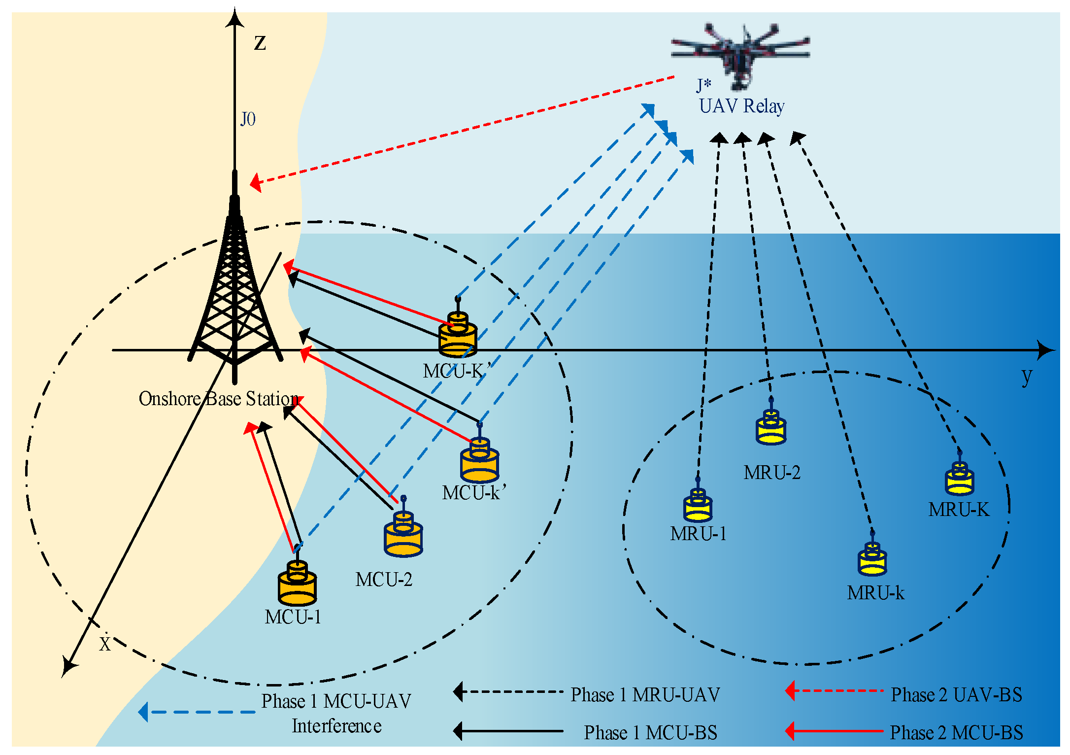
  • In this paper, we study the power minimization problem subject to user’s minimum rate requirement and UAV transmit power budget in a maritime IoT system with A2A and A2S link model considered. A coordinated direct and relay transmission scheme employing uplink NOMA scheme is proposed and investigated, where maritime close-shore users (MCU) directly communication with onshore BS, whereas maritime remote users (MRU) communicate with the onshore BS by a half-duplex DF UAV relay.
  • In the proposed maritime IoT system, an interference cancellation parameter is introduced to summarized UAV’s received data expression in transmission phase 1, which facilitates solving the proposed UAV power transmission minimization problem.
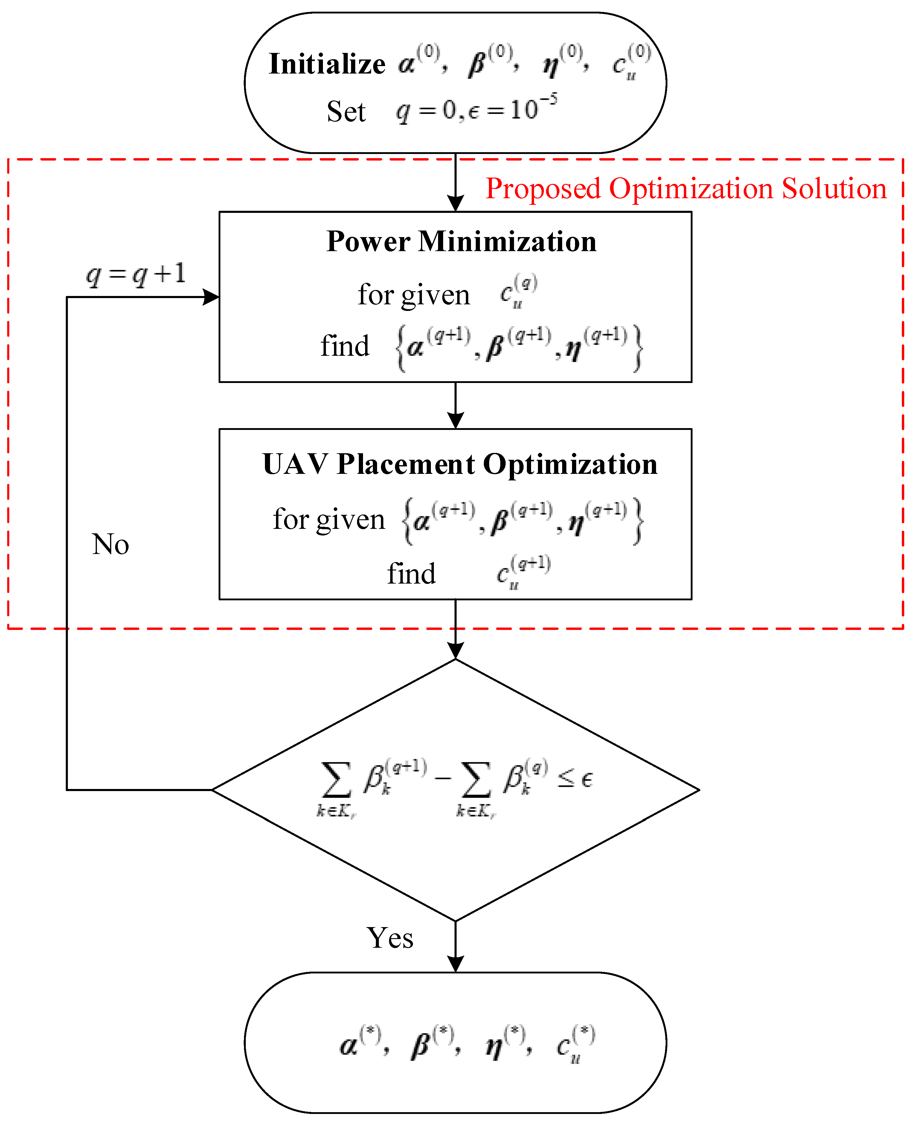
  • The successive convex approximation method is applied to deal with non-convex inequality constraints of the formulated optimization problem. The block coordinate descent method (BCD) is used to decouple the original problem into two subproblems, namely power allocation and optimal UAV placement. After that, an iterative algorithm is proposed to optimize power allocation coefficients and optimal UAV coordinates alternately.

1.3. Paper Organization

The rest of this work is organized as follows. In Section 2, the interested UAV-assisted maritime IoT system model and formulated optimization problem are proposed. Section 3 presents joint power allocation and an optimal UAV placement solution to the optimization problem. Numerical results are presented in Section 4. Finally, Section 5 concludes our paper.

2. System Model and Problem Formulation

2.1. System Model

As shown in Figure 1, a UAV-assisted maritime IoT system model, including one onshore base station (BS), one mobile UAV relay, and multiple maritime users deployed on a certain area for data collection, is considered. These maritime users are divided into two groups, including K maritime close-shore users (MCU) and K maritime remote users (MRU), according to communication service type. K c = k k K c , K c = K and K r = k k K r , K r = K denote the MRUs set and MCUs set, respectively. It is assumed that all transmission nodes in this model are equipped with a single antenna, K r K c = . MCUs are deployed closely along the coastline and can be served directly by the onshore BS. MRUs are deployed far away from the coastline and must rely on a UAV relay for data ferrying. A coordinated direct and relay transmission is introduced, where an MCU directly communicates with an onshore BS, whereas an MRU communicates with an onshore BS by a half-duplex DF UAV relay. A two-user uplink NOMA scheme is considered by an MRU coexisting with an MCU in a spectrum resource block. In this paper, we focus on total transmit power minimum optimization of UAV relay by jointly optimizing power allocation and UAV hovering position. It is assumed that K r = K c = K . Thus, there are K NOMA pairs in the proposed networks.
The three-dimensional Cartesian coordinate is considered, where the coastline is approximated as the x-axis, the y-axis extends into the ocean, and the z-axis represents the altitude. The coordinate of the onshore BS is c B = 0 , 0 , h . Although locations of maritime users may change along with time according to sea surface waves, their coordinates can still be regarded as approximately fixed in a certain period, which can be denoted as  c k = x k , y k , 0 , k K r and c k = x k , y k , 0 , k K c , respectively. The UAV departs from the starting point J 0 , then flys to the optimal hovering position J * for the data relaying mission, and finally returns to the original location. According to the pre-planned deployed position of maritime users, the optimal hovering position of the UAV can be predetermined before its mission executes. Thus, the coordinates of the UAV can be expressed as  x u , y u , h u during the transmission mission’s executed duration. Denote the distances between BS and the UAV, between the UAV and the k-th MRU, and between the  k -th MCU, respectively, as:
d U B = c u c B = x u x B 2 + y u y B 2 + h u 2
d B k = c B c k = x B x k 2 + y B y k 2 + h 2
d U k = c u c k = x u x k 2 + y u y k 2 + h u 2 , k K r
d U k = c u c k = x u x k 2 + y u y k 2 + h u 2 , k K c
We assume that the UAV flies high enough to enable an LoS transmission. An air-to-sea (A2S) channel model is composed by large-scale and small-scale fading [15]. Thus, the channel between UAV and k-th MRU can be represented as:
h U k = 1 L U k 1 / 2 h ˜ U k , k
where L U k denotes the path loss component and h ˜ U k denotes the Rician fading component. Then, the path loss model can be expressed as:
L U k dB = A U + 10 ς U log 10 d U k d 0 + X U
where d 0 refers to the reference distance, A U denotes the path loss at  d 0 , ς U denotes the path loss exponent, and X U is a zero-mean Gaussian random variable with standard deviation σ X U [22,23]. Rician fading can be represented as:
h ˜ U k = S U 1 + S U + 1 1 + S U g U k
where g U k CN 0 , 1 and S U indicates the Rician factor that corresponds to the ratio between the LoS power and the scattering power [24]. In the proposed system, the maritime users are deployed on pre-planned positions, then their location data can be pre-measured. Although locations of MRUs and MCUs may change along with time according to sea surface waves, their coordinates can still be regarded as approximately fixed in a certain period. Thus, their corresponding large-scaled channel state information (CSI) can be obtained. Similarly, the A2S channel between onshore BS and k -th MCU is denoted as:
h B k = d 0 d B k ς U 2 10 A U + X U 20 S U 1 + S U + 1 1 + S U g B k
where g B k CN 0 , 1 . The interference A2S link between UAV and k -th MCU is denoted as:
h U k = d 0 d U k ς U 2 10 A U + X U 20 S U 1 + S U + 1 1 + S U g U k
where g U k CN 0 , 1 . On the other hand, The air-to-air (A2A) channel between onshore BS and UAV has a high LoS probability, which can be represented as:
h U B = d 0 d U B t ς U B 2 10 A U B + X U B 20 S U B 1 + S U B + 1 1 + S U B g U B
where A U B denotes the path loss at  d 0 , ς U B denotes the path loss exponent, X U B is a zero-mean Gaussian random variable with standard deviation, S U B is the Rician factor, and σ X U B and g U B CN 0 , 1 .
For each transmission duration, the UAV receives data from an MRU in Phase 1 and then forwards it to BS in phase 2; meanwhile, an MCU transmits data to BS in the same subchannel with the MRU in both phases by uplink NOMA. With loss of generality, we consider h B k 2 h U B 2 h B k 2 .
1.
Phase-1 ( t 1 )
In an uplink NOMA transmission scenario, an MCU and an MRU transmit symbols x 1 and y 1 simultaneously with α k P t and α k P t , where P t denotes the total transmit power in phase 1. α k and α k are the power allocation coefficient in phase 1. To guarantee an efficient SIC decoding at the NOMA receiver, it is assumed that α k + α k = 1 . Thus, data received at onshore BS and the UAV in Phase 1 can be given, respectively, by:
y B k t 1 = h B k α k P t x 1 t 1 + w
y U k t 1 = h U k α k P t x 1 t 1 + α k P t y 1 t 1 + w
where w CN 0 , σ 2 denotes the background noise. Due to the half-duplex relay scheme, the achievable rate of  the k -th MCU at BS in phase 1 can be represented as:
R B k t 1 = 1 2 log 2 1 + α k P t h B k 2 σ 2 = 1 2 log 2 1 + α k ρ t h B k 2
where P t ρ 2 = ρ t . Because of the simultaneous transmission of MRU and MCU, UAV is able to receive the signal from both of them. We assume perfect time synchronization between MRU and MCU. According to the uplink NOMA principle, the UAV relay obtains the decoded symbol y 1 by considering the following two conditions.
  • h U k 2 h U k 2
    R U k t 1 = 1 2 log 2 1 + α k P t h U k 2 α k P t h U k 2 + σ 2 = 1 2 log 2 1 + α k ρ t h U k 2 α k ρ t h U k 2 + 1
  • h U k 2 h U k 2
    R U k t 1 = 1 2 log 2 1 + α k P t h U k 2 σ 2 = 1 2 log 2 1 + α k ρ t h U k 2
By introducing κ 0 , 1 as the interference cancellation parameter, the received data rate at UAV in Phase 1 can be summarized as:
R U k t 1 = log 2 1 + α k ρ t h U k 2 κ α k ρ t h U k 2 + 1 = log 2 1 + α k ρ t h U k 2 κ = 0 , h U k 2 h U k 2 log 2 1 + α k ρ t h U k 2 α k ρ t h U k 2 + 1 κ = 1 , h U k 2 h U k 2
2.
Phase-2 ( t 2 )
In phase 2, both MCU and UAV transmit symbols x 2 and y 1 simultaneously to onshore BS with powers β k P t and β k P t , where β k , β k are the power allocation coefficient in phase 2 and β k + β k = 1 . Thus, received data at onshore BS can be represented as:
y B U k t 2 = h U B P k 2 y 1 t 2 + h B k P k 2 x 2 t 2 + w
Since h U B 2 h B k 2 , the achievable data rates of the UAV relay and MCU are presented, respectively, by:
R U B t 2 = 1 2 log 2 1 + β k P t h U B 2 σ 2 = 1 2 log 2 1 + β k ρ t h U B 2
R B k t 2 = 1 2 log 2 1 + β k P t h B k 2 β k P t h U B 2 + σ 2 = 1 2 log 2 1 + β k ρ t h B k 2 β k ρ t h U B 2 + 1
3.
Sum Capacity
Using Equations (13) and (19), the sum capacity of the k -th MCU is given as:
R k = R B k t 1 + R B k t 2
On the other hand, the end-to-end capacity of a two-hop cooperative link is the minimum one of the two hops. Thus, according to Equations (16) and (18), the capacity of MRU is obtained as:
R k = min R U k t 1 , R U B t 2

2.2. Problem Formulation

It is assumed that the UAV fights with a fixed altitude, which means h u is constant. Since the transmission duration and fighting trajectory for each relay mission is predetermined, the propulsion energy and hovering energy required for the UAV is also considered before. The UAV transmit power minimization problem has formulated constraints on maritime users’ minimum rate requirements, maritime maximum users’ transmit power thresholds and UAV power budget, which can be summarized as:
P 1 min α , β , x u , y u P U A V s . t . C 1 : P U A V P ¯ U t δ 2 , k C 2 : α k 0 , α k 0 , β k 0 , β k 0 , k , k C 3 : α k + α k = 1 , β k + β k = 1 , k , k C 4 : min R U k t 1 , R U B t 2 R ¯ k , k C 5 : R B k t 1 R ¯ k , k C 6 : R B k t 2 R ¯ k , k
where P U A V = k K r β k ρ t denotes the total transmitted energy consumption of UAV during mission execution. α = α 1 , , α k , , α K and β = β 1 , , β k , , β K denote power coefficient vectors of K NOMA pairs. P ¯ U t denotes the transmit power budget of UAV. C1 guarantees the power supplied by UAV is not exceeding its transmit power budget. C2 and C3 are the power allocation coefficient constraints. C4–C6 can guarantee the minimum rate requirements of two types of maritime users. To solve (P1), we first introduce K slack variables η k = min R U k t 1 , R U B t 2 , k into the objective function such that it is reformulated as:
P 2 min α , β , x u , y u , η P U A V s . t . C 7 : R U k t 1 η k , k C 8 : R U B t 2 η k , k C 1 C 6
where η = η 1 , , η k , , η K denotes the slack variables vector of  R k . Thus, (P2) can be transformed as:
P 3 min α , β , x u , y u , η P U A V s . t . C 4 : α k λ k g B k 2 + λ k ρ t h U k 2 + λ k g B k 2 , β k λ k ρ t h U B 2 C 5 : α k h B k 2 λ k ρ t h B k 2 C 6 : β k h B k 2 λ k ρ t λ k h U B 2 + h B k 2 C 1 3 , C 7 8
where λ k = 2 2 R ¯ k 1 and λ k = 2 2 R ¯ k 1 . (P3) is still challenging to solve since C7 and C8 are non-convex to  α and β . For the UAV placement optimization problem, there are two sorts of optimization approaches, namely the deterministic optimization method and stochastic optimization method [25]. The BCD approach is a computationally-efficient deterministic approach that can be used to solve joint UAV placement and resource allocation problem by iteratively optimizing two block variables in turn [26]. Therefore, we introduce the BCD optimization method to decouple the original problem into a power allocation problem and optimal UAV placement and optimize two block variables alternately.

3. Proposed Optimization Solution

3.1. Power Minimization

With the given optimum UAV hovering placement, the power minimization problem can be transformed as:
P 4 min α , β , η P U A V s . t . C 7 : R U k t 1 = 1 2 log 2 1 + α k ρ t h U k 2 κ 1 α k h U k 2 + 1 η k , k C 8 : R U B t 2 = log 2 1 + β k ρ t h U B 2 η k , k C 1 C 3 , C 4 , C 5 , C 6
where C8 is non-convex inequality constraint since log 2 1 + β k ρ t h U B 2 is concave. C7 can be transformed as:
R U k t 1 = log 2 α k ρ t h U k 2 κ h U k 2 + ρ t g U k 2 + 1 log 2 κ 1 α k ρ t h U k 2 + 1 2 η k , k
which is a non-convex inequality constraint since log 2 α k ρ t h U k 2 κ h U k 2 + ρ t g U k 2 + 1 is concave and log 2 κ 1 α k ρ t h U k 2 + 1 is convex. To tackle the non-convexity of C7 and C8, we introduce the successive convex approximation (SCA) method. By giving any local point α ¯ k , the upper bound of  R U k t 1 can be obtained as:
R U k t 1 ( upper ) = log 2 α k ρ t h U k 2 κ h U k 2 + κ ρ t h U k 2 + 1 log 2 κ 1 α k ρ t h U k 2 + 1 + ρ t h U k 2 κ h U k 2 α k α ¯ k ln 2 α k ρ t h U k 2 κ h U k 2 + κ ρ t h U k 2 + 1
Similarly, the left-side of C8 is concave with respect to  β k . Given any local point β ¯ k , the upper bound of  R U k t 2 is obtained as:
R U B t 2 ( upper ) = log 2 1 + β k ρ t h U B 2 + ρ t h U B 2 ln 2 1 + β k ρ t h U B 2 β k β ¯ k
Then, (P4) can be approximated by:
P 5 min α , β , η P U A V s . t . C 7 : η k R U k t 1 ( upper ) C 8 : η k R U B t 2 ( upper ) C 1 C 3 , C 4 C 6
(P5) is convex with respect to  α , β and η , which can be solved by the interior point method.

3.2. UAV Placement Optimization

With the given power allocation coefficients, (P1) can be rewritten as:
P 6 min x u , y u k K r β k ρ t s . t . C 6 : log 2 1 + β k ρ t h B k 2 d U B ς U β k ρ t φ U B 2 + d U B ς U 2 R ¯ k , k C 7 : log 2 1 + α k ρ t φ U k 2 d U k ς U κ α k ρ t φ U k 2 d U k ς U + d U k ς U d U k ς U 2 η k , k C 8 : log 2 1 + β k ρ t φ U B 2 d U B ς U 2 η k , k
where,
φ U B = 10 A U B + X U B 20 · d 0 ς U B 2 S U B 1 + S U B + 1 1 + S U B g U B
φ U k = 10 A U + X U 20 · d 0 ς U 2 S U 1 + S U + 1 1 + S U g U k ,
φ U k = 10 A U + X U 20 · d 0 ς U 2 S U 1 + S U + 1 1 + S U g U k .
(P6) is non-convex for its three non-convex constraints. By the SCA method, C6″ is transformed into:
log 2 β k ρ t φ U B 2 + d U B ς U + β k ρ t h B k 2 d U B ς U log 2 β k ρ t φ U B 2 + d U B ς U 2 R ¯ k
By introducing a slack variable Z 1 , C6″ are equivalent to the following two constraints as:
log Z 1 log 2 β k ρ t φ U B 2 + d U B ς U 2 R ¯ k log 2 β k ρ t φ U B 2 + d U B ς U + β k ρ t h B k 2 d U B ς U Z 1
Then, we approximate the above equations by their lower bounds. The item log 2 β k ρ t φ U B 2 + d U B ς U in Equation (35) is convex with respect to  d U B ς U . d U B ς U is convex with respect to  c u = x u , y u , h u , where h u is constant. Thus, given any c ¯ u = x ¯ u , y ¯ u , h u , Equation (35) can be approximated by their lower bound as:
log Z 1 log 2 β k ρ t φ U B 2 + d c ¯ u , c B ς U B ς U B d c ¯ u , c B ς U B 1 c ¯ u c B T c u c ¯ u ln 2 β k ρ t φ U B 2 + d c ¯ u , c B ς U B 2 R ¯ k
β k ρ t φ U B 2 + 1 + β k ρ t h B k 2 d c ¯ u , c B ς U B + d c ¯ u , c B ς U B 1 c ¯ u c B T c u c ¯ u Z 1
where d c ¯ u , c B = c ¯ u c B . Apparently, the left-side of  Equations (36) and (37) are concave with respect to  c u = x u , y u , η k and Z 1 . Similarly, the non-convex constraints C7″ and C8″ are approximated by their lower bounds:
log Z 2 log 2 κ α k ρ t φ U k 2 d U k ς U + d U k d U k ς U ς U κ α k ρ t φ U k 2 d c ¯ u , c k 1 + d c ¯ u , c k ς U 1 c ¯ u c k T c u c ¯ u ln 2 κ α k ρ t φ U k 2 + d c ¯ u , c k ς U 2 η ¯ k
ς U d c ¯ u , c k ς U 1 c ¯ u c k T c u c ¯ u d c ¯ u , c k 2 ς U + κ α k ρ t φ U k 2 d c ¯ u , c k ς U 1 + c ¯ u c k T c u c ¯ u d c ¯ u , c k + α k ρ t φ U k 2 d c ¯ u , c k ς U 1 + c ¯ u c k T c u c ¯ u d c ¯ u , c k Z 2
where d c ¯ u , c k = c ¯ u c k , d c ¯ u , c k = c ¯ u c k .
log Z 3 log 2 d c ¯ u , c B ς U B ς U B d c ¯ u , c B ς U B 1 c ¯ u c B T c u c ¯ u ln 2 d c ¯ u , c B ς U B 2 η k
β k ρ t φ U B 2 + d c ¯ u , c B ς U B + d c ¯ u , c B ς U B 1 c ¯ u c B T c u c ¯ u Z 3
where Z 2 and Z 3 are the slack variable introduced to C7″ and C8″, respectively, and c ¯ u is the local point of the UAV coordinate obtained in the last iteration. Thus, the optimum solution of (P6) is always lower bounded by:
P 7 min c u , η k K r β k ρ t s . t . ( 36 ) , ( 37 ) , ( 38 ) , ( 39 ) , ( 40 ) , ( 41 ) , k , k

3.3. Iterative Algorithm

Based on the solutions to the two sub-problems, we propose an iterative algorithm for (P2) by using the BCD method, which is guaranteed to cover a sub-optimum [27] (In [27]; its BCD-based algorithm contains an additional feasibility checking to guarantee the feasibility of its proposed optimization problem), as summarized in Algorithm 1. Different from [27], the optimal results are acquired in feasible sets obtained in Equation (29) and Equation (42) by Algorithm 1 without additional feasibility checking. q and ϵ are denoted as the number of iteration times and the algorithm convergence factor.
Algorithm 1 BCD Method for Joint Placement and Power Optimization
  • Initialize α ( 0 ) , β ( 0 ) , η ( 0 ) and c u let q = 0 , ϵ = 10 5
  • repeat
  •     Solve (P5) for given c u ( q ) , and denote the optimal solution as  α q + 1 , β q + 1 , η q + 1
  •     Solve (P7) for given α q + 1 , β q + 1 η q + 1 , and denote the optimal solution as  c u q + 1
  •     Update q = q + 1
  • until k K r β k q + 1 k K r β k q ϵ
The flowchart of Algorithm 1 is present in Figure 2, which shows the iterative procedure of the proposed optimization solution of joint UAV placement and power optimization. In this paper, we introduce the BCD method to alternately solve the power allocation problem and UAV optimal placement problem by convex optimization. Firstly, initial values α 0 , β 0 , η 0 and c u 0 are given and the BCD method is applied to optimize the variables block with the other variables block fixed. Then, we repeat the iteration until the UAV transmitted power minimization is obtained due to its convergence. Finally, the optimal power allocation α * , β * , η * and UAV position coordinates c u * can be derived. In addition, Algorithm 1 yields a suboptimal solution, due to the optimal solution obtained by two suboptimal problems.

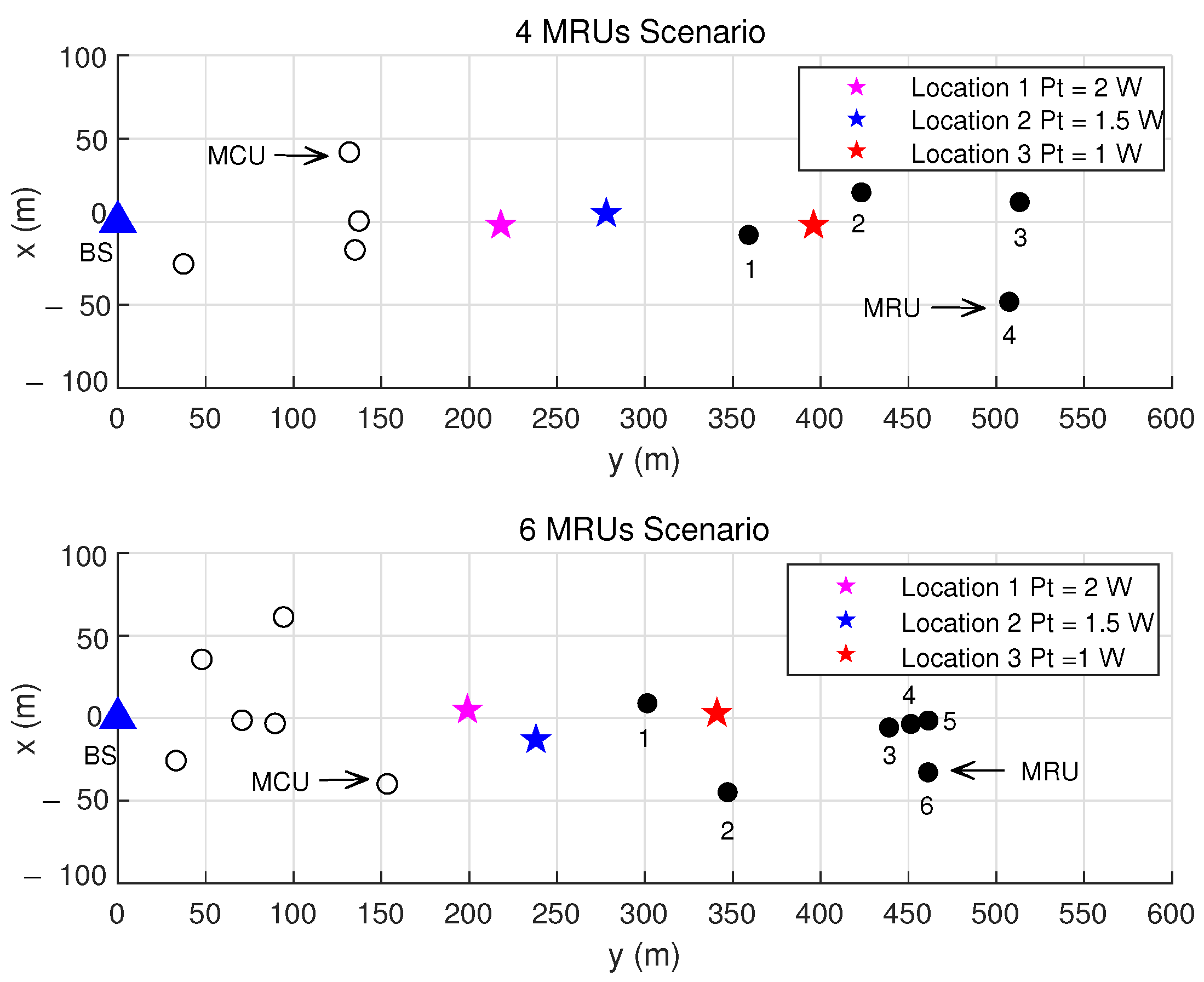
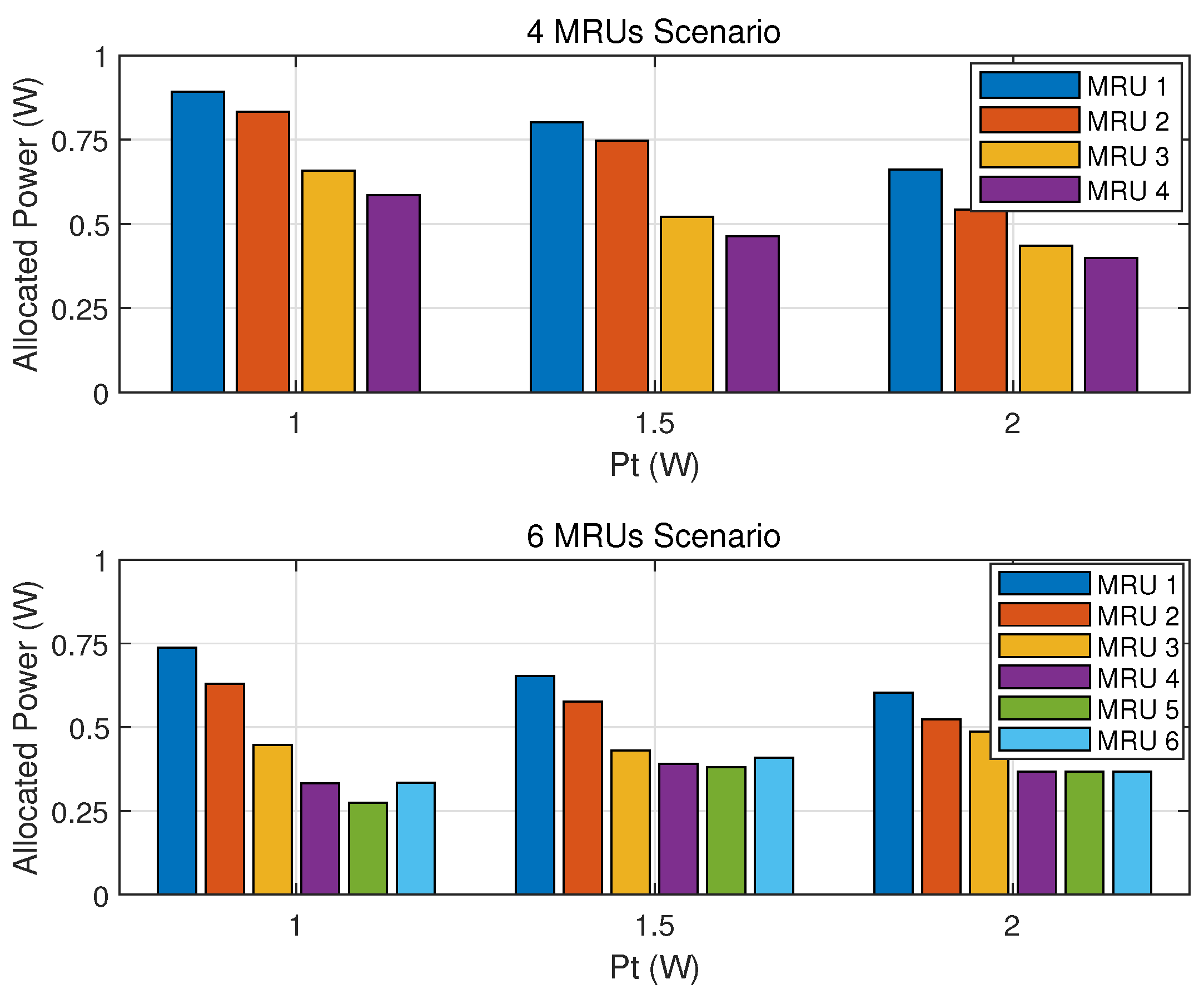
4. Numerical Results and Discussion

In this section, we simulate a maritime IoT UAV-relaying network with K pairs of maritime users. The coordinates of onshore BS are 0 , 0 , 150 . The onshore BS coverage is a circle with 200 m as radius. K MCUs are randomly located along the coastline within the onshore BS service area. K MRUs are randomly located in a square area of 200 × 200 m2 with coordinates 0 , 400 , 0 . The constant altitude of UAV is set as h u = 150 m. Set UAV power budget P ¯ U t = 4 W, δ 2 = 108 dBm, the carrier frequency f c = 5 MHz, d 0 = 1 m, light speed c = 3 × 10 8 m/s. The parameters of the channel models in maritime propagation environment can be obtain by [22]. The simulation parameters are given in Table 1.
Figure 3 shows the optimized horizontal locations of UAV with different transmit power budget. Both the K = 4 NOMA pair scenario and K = 6 NOMA pair scenario are discussed in this part. We set the minimum rate requirement R ¯ k = R ¯ k = 0.5 bps/Hz. The optimized UAV locations with a NOMA pair total transmit power P t = 1 W, 1.5 W and 2 W are marked with colored star markers. It shows that there exists an optimal hovering position, which achieves the tradeoff between UAV transmit power minimization and MRU’s minimum rate requirements. It can be seen in Figure 3 that with higher maritime user pair total transmit power, the UAV should hover closer to the onshore BS to enjoyed better A2A channels. Then, the UAV relay consumes less energy. Moreover, with the number of MRUs increasing, the UAV should hover closer to the onshore BS to serve more MRUs within its power budget. Figure 4 illustrates the power allocation results of UAV for each MRU data ferrying with various NOMA pair’s total transmitted power, according to the optimal position in Figure 3. It is indicated that UAV consumes less power for hovering closer to onshore BS and enjoying a better A2A link. Furthermore, at the same hovering position, UAV allocates more power for the MRU that is closer to relay data since UAV receives a higher MRU rate with better A2S channel condition.
Figure 5 demonstrates that the required UAV transmits power with various NOMA total transmitted power pairs P t in the K = 4 NOMA pairs scenario. We set the same dMCU rate requirement as the MRUs. Specifically, randomly searched UAV placement scheme (In the randomly searched UAV placement scheme, the UAV coordinates are obtained after several times randomly searching in the feasible region. The number of searching times is predetermined. This scheme is also used as a benchmark in [8,18].) is employed as a benchmark with 10 times random search. The proposed optimized power allocation is applied as a power allocation scheme. It shows in Figure 5 that UAV requires more total transmitted power by increasing MRU’s rate requirement. With the increasing of P t , the required UAV’s transmitted power decreases. It is shown that, compared with a randomly searched location scheme, the UAV transmit power decreases over 7% with R ¯ k = 0.45 bps/Hz, over 3% with R ¯ k = 0.5 bps/Hz, and over 3% with R ¯ k = 0.55 bps/Hz, respectively. Furthermore, it is illustrated that our proposed optimal algorithm outperforms the benchmark scheme.
The impact of the MRU rate requirements to the required UAV transmitted power is evaluated in Figure 6 with a NOMA pair total transmitted power P t = 1 W. The 1.5 W and 2 W K = 4 NOMA pair scenario is discussed in this part. We set the same MCU rate requirement as the MRUs. It shows that more UAV transmitted power is required by the increasing MRU rate requirement with more transmitted power to guarantee higher data rate requirements. It is shown that compared with randomly searched location scheme, the UAV transmit power decrease over 2% with P t = 1 W, over 4% with P t = 1.5 W and 7% with P t = 2 W, respectively. It is worth noting that the curve of UAV transmitted power grows smoothly with higher rate requirements compared to lower rate requirements. The reason is that with the increasing user rate requirement, more transmitted power is allocated to MCU to guarantee its minimum rate requirement, which has no extra channel gain due to its fixed position, whereas the MRU can obtain a better data rate with better A2A channel condition.

5. Conclusions

In this paper, a UAV was utilized as a relay to help offshore maritime users connect with onshore BS. The UP-NOMA scheme was proposed to increase system spectrum efficiency. The optimal UAV hovering placement and transmitted power allocation were jointly optimized to minimize the total transmitted power consumption of the UAV relay energy with constraints of the minimum maritime user rate requirements and transmitters’ power budgets. The SCA method was applied to deal with the non-convexity of the proposed optimization problem and the BCD method was employed to generate an iterative algorithm for successively optimizing two sub-problems. Numerical results indicate that the proposed algorithm outperformed the benchmark algorithm and shed light on the potential for exploiting the energy-limited aerial relay in IoT systems.

Author Contributions

Conceptualization, W.X.; methodology, W.X.; software, W.X.; validation, W.X.; formal analysis, W.X.; investigation, W.X., J.T. and L.G.; resources, W.X.; data curation, W.X.; writing—original draft preparation, W.X.; writing—review and editing, W.X., J.T., L.G. and S.T.; visualization, W.X.; supervision, W.X.; project administration, W.X.; funding acquisition, W.X. All authors have read and agreed to the published version of the manuscript.

Funding

This research was funded by the Shanghai Sailing Program, grant number 20YF1416700, the Innovation Program of Shanghai Municipal Education Commission of China under Grant 2021-01-07-00-10-E00121, the National Natural Science Foundation of China (62271303).

Data Availability Statement

Not applicable.

Conflicts of Interest

The authors declare no conflict of interest.

References

  1. Li, X.; Feng, W.; Wang, J.; Chen, Y.; Ge, N.; Wang, C.X. Enabling 5G on the ocean: A hybrid satellite-UAV-terrestrial network solution. IEEE Wirel. Commun. 2020, 27, 116–121. [Google Scholar] [CrossRef]
  2. Lopes, M.J.; Teixeira, F.; Mamede, J.B.; Campos, R. Wi-Fi broadband maritime communications using 5.8 GHz band. In Proceedings of the Underwater Communications Networking, Levante, Italy, 3–5 September 2014. [Google Scholar]
  3. Teixeira, F.B.; Campos, R.; Ricardo, M. Height optimization in aerial networks for enhanced broadband communications at sea. IEEE Access 2020, 8, 28311–28323. [Google Scholar] [CrossRef]
  4. Ji, X.; Wang, J.; Li, Y.; Sun, Q.; Xu, C. Modulation recognition in maritime multipath channels: A blind equalization-aided deep learning approach. China Commun. 2020, 17, 12–25. [Google Scholar] [CrossRef]
  5. Wei, T.; Feng, W.; Chen, Y.; Wang, C.X.; Ge, N.; Lu, J. Hybrid satellite-terrestrial communication networks for the maritime internet of things: Key technologies, opportunities, and challenges. IEEE Internet Things J. 2021, 8, 8910–8934. [Google Scholar] [CrossRef]
  6. Wang, N.; Li, F.; Chen, D.; Liu, L.; Bao, Z. NOMA-based energy-efficiency optimization for UAV enabled space-air-ground intergarted relay networks. IEEE Trans. Veh. Technol. 2022, 71, 4129–4141. [Google Scholar] [CrossRef]
  7. Liu, C.; Feng, W.; Chen, Y.; Wang, C.X.; Ge, N. Cell-Free Satellite-UAV Networks for 6G Wide-Area Internet of Things. IEEE J. Sel. Areas Commun. 2021, 39, 1116–1131. [Google Scholar] [CrossRef]
  8. Liu, X.; Wang, J.; Zhao, N.; Chen, Y.; Zhang, S.; Ding, Z.; Yu, F.R. Placement and power allocation for NOMA-UAV networks. IEEE Wirel. Commun. Lett. 2019, 8, 965–968. [Google Scholar] [CrossRef] [Green Version]
  9. Sharma, P.K.; Kim, D.I. UAV-enabled downlink wireless system with non-orthogonal multiple access. In Proceedings of the 2017 IEEE Globecom Workshops (GC Wkshps), Singapore, 4–8 December 2017. [Google Scholar]
  10. Sohail, M.F.; Leow, C.Y.; Won, S. Non-orthogonal multiple access for unmanned aerial vehicle assisted communication. IEEE Access 2018, 6, 22716–22727. [Google Scholar] [CrossRef]
  11. Nasir, A.A.; Tuan, H.D.; Duong, T.Q.; Poor, H.V. UAV-enabled communication using NOMA. IEEE Trans. Commun. 2019, 67, 5126–5138. [Google Scholar] [CrossRef] [Green Version]
  12. Wang, J.; Zhou, H.; Li, Y.; Sun, Q.; Wu, Y.; Jin, S.; Quek, T.Q.S.; Xu, C. Wireless channel models for maritime communications. IEEE Access 2018, 6, 68070–68088. [Google Scholar] [CrossRef]
  13. Zhang, J.; Liang, F.; Li, B.; Yang, Z.; Wu, Y.; Zhu, H. Placement optimization of caching mobile relay maritime communication. China Commun. 2020, 17, 209–219. [Google Scholar] [CrossRef]
  14. Tang, R.; Feng, W.; Chen, Y.; Ge, N. NOMA-based UAV communications for maritime coverage enhancement. China Commun. 2021, 18, 230–243. [Google Scholar] [CrossRef]
  15. Li, X.; Feng, W.; Chen, Y.; Wang, C.X.; Ge, N. Maritime coverage enhancement using UAVs coordinated with hybrid satellite-terrestrial networks. IEEE Trans. Commun. 2020, 68, 2355–2369. [Google Scholar] [CrossRef] [Green Version]
  16. Ma, R.; Wang, R.; Liu, G.; Chen, H.H.; Qin, Z. UAV-assisted data collection for ocean monitoring networks. IEEE Netw. 2020, 34, 250–258. [Google Scholar] [CrossRef]
  17. Lyu, L.; Chu, Z.; Lin, B.; Dai, Y.; Cheng, N. Fast trajectory planning for UAV-enabled maritime IoT systems: A Fermat-Point based approach. IEEE Wirel. Commun. Lett. 2022, 11, 328–332. [Google Scholar] [CrossRef]
  18. Jiang, X.; Wu, Z.; Yin, Z.; Yang, Z.; Zhao, N. Power comsumption minimization of UAV relay in NOMA networks. IEEE Wirel. Commun. Lett. 2020, 9, 666–670. [Google Scholar] [CrossRef]
  19. Guo, Y.; Yin, S.; Hao, J. Joint placement and resource optimization for multi-user UAV-relaying system with underlaid cellular networks. IEEE Trans. Veh. 2020, 10, 12374–12377. [Google Scholar] [CrossRef]
  20. Wang, D.; Zhou, F.; Lin, W.; Ding, Z.; Al-Dhahir, N. Cooperative Hybrid Non-Orthogonal Multiple Access Based Mobile-Edge Computing in Cognitive Radio Networks. IEEE Trans. Cogn. Commun. Netw. 2022, 8, 1104–1117. [Google Scholar] [CrossRef]
  21. Wang, D.; He, T.; Zhou, F.; Cheng, J.; Zhang, R.; Wu, Q. Outage-driven link selection for secure buffer-aided networks. Sci. China Inf. Sci. 2022, 65, 182303. [Google Scholar] [CrossRef]
  22. Matolak, D.W.; Sun, R. Air-ground channel characterization for unmanned aircraft systems—Part I: Methods, measurements, and models for over-water settingse. IEEE Trans. Veh. Technol. 2017, 66, 26–44. [Google Scholar] [CrossRef]
  23. Wu, S.; Wang, C.X.; Alwakeel, M.M.; You, X. A general 3-D non-stationary 5G wireless channel model. IEEE Trans. Commun. 2018, 66, 3065–3078. [Google Scholar] [CrossRef]
  24. Zeng, L.; Cheng, X.; Wang, C.X.; Yin, X. Second order statistics of non-isotropic UAV Ricean fading channels. In Proceedings of the IEEE 86th Vehicle Technology Conference (VTC-Fall), Toronto, ON, Canada, 24–27 September 2017. [Google Scholar]
  25. Kang, Z.; You, C.; Zhang, R. 3D Placement for Multi-UAV Relaying: An Iterative Gibbs-Sampling and Block Coordinate Descent Optimization Approach. IEEE Trans. Commun. 2021, 69, 2047–2062. [Google Scholar] [CrossRef]
  26. Wang, D.; Wu, M.; He, Y.; Pang, L.; Xu, Q.; Zhang, R. An HAP and UAVs Collaboration Framework for Uplink Secure Rate Maximization in NOMA-Enabled IoT Networks. Remote. Sens. 2022, 14, 4501. [Google Scholar] [CrossRef]
  27. Huang, W.; Yang, Z.; Pan, C.; Pei, L.; Chen, M.; Shikh-Bahaei, M.; Elkashlan, M.; Nallanathan, A. Joint power, altitude, location and bandwidth optimization for UAV with underlaid D2D communications. IEEE Wirel. Commun. Lett. 2019, 8, 524–527. [Google Scholar] [CrossRef]
Figure 1. System model of maritime IoT system with a UAV relay.
Drones 06 00304 g001
Figure 2. The flowchart of Algorithm 1.
Drones 06 00304 g002
Figure 3. Horizontal locations of UAV with different NOMA total power pairs P t .
Drones 06 00304 g003
Figure 4. Power allocation of UAV to BS for each MRU with different NOMA total power pairs P t .
Drones 06 00304 g004
Figure 5. UAV transmit power with different NOMA pair total power P t .
Drones 06 00304 g005
Figure 6. UAV transmitted power with different MRU rate requirements R ¯ k .
Drones 06 00304 g006
Table 1. Simulation parameters.
ParameterDescriptionValue
c B Coordination of onshore BS 0 , 150 , 0
h u Flight altitude of UAV150 m
d 0 Reference distance1 m
f c Carrier frequency5 MHz
σ 2 Background noise 108 dBm
cLight speed 3 × 10 8 m/s
P ¯ U t UAV transmit power budget4 W
A U A2S link path loss at  d 0 116.7
ς U A2S link path loss exponent20
δ X U standard deviation of  X U 0.1
S U A2S link Rician factor30
A U B A2A linkpath loss at  d 0 46.4
ς U B A2A link path loss exponent15
δ X U B standard deviation of  X U B 0.1
S U B A2A link Rician factor10
Publisher’s Note: MDPI stays neutral with regard to jurisdictional claims in published maps and institutional affiliations.

