
Fuzzy Fractional Order PID Tuned via PSO for a Pneumatic Actuator with Ball Beam (PABB) System
 , ,
, ,
Abstract
:1. Introduction
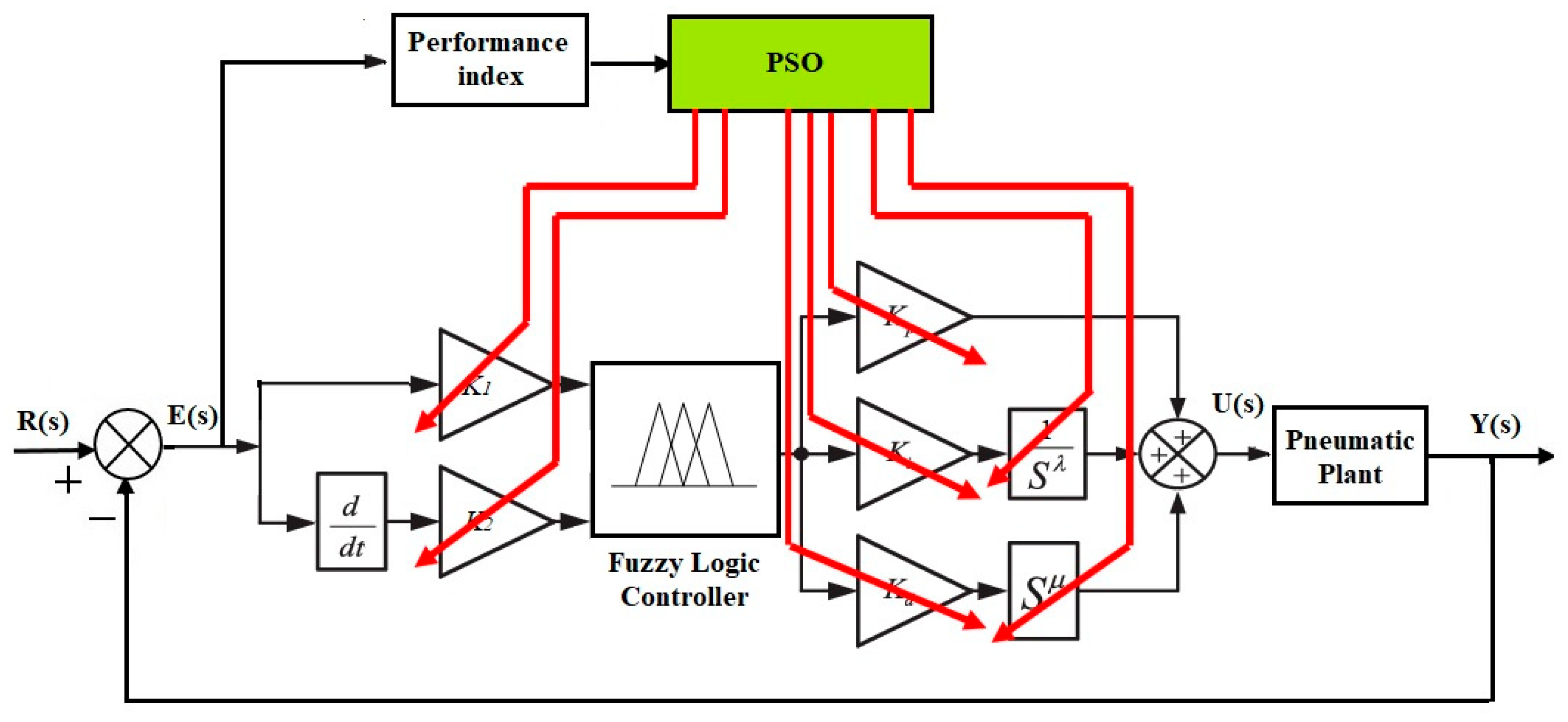
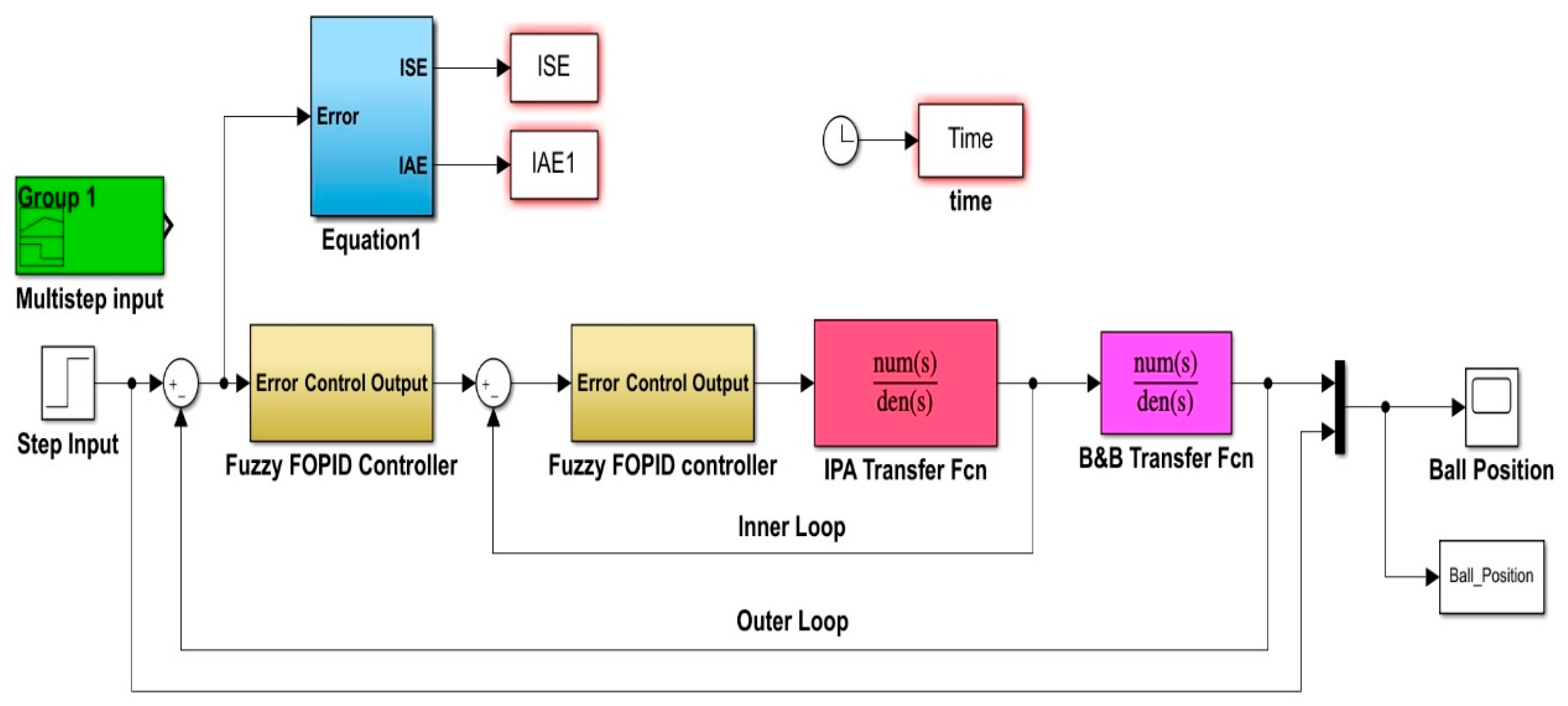
- Developing a two-input-one-output fuzzy controller for the intelligent pneumatic actuator system and assessing its performance in the positioning system. This design incorporates FOPID, which is connected to the output terminal of the fuzzy controller to produce the proposed Fuzzy FOPID controller.
- Utilizing the Particle Swarm Optimization (PSO) technique to identify the optimal values for the suggested controller parameters. Seven parameters are adjusted to achieve the best dynamic behavior for the Fuzzy FOPID controller.
- Validating the superiority of the proposed design by comparing the results obtained from simulations and real-world environments with those of the Fuzzy FOPID.
- Developing a Pneumatic Actuated Ball and Beam System and implementing the Fuzzy FOPID controller on the system.
- Validating the performance of the position controller through both simulation and real-time experiments.
2. System Modelling
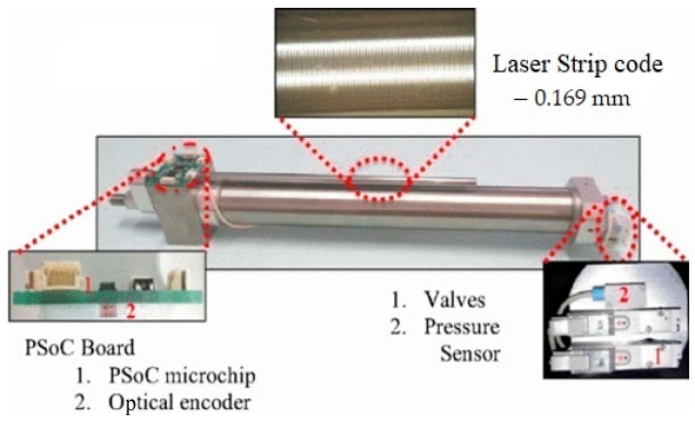
2.1. Intelligent Pneumatic Actuator (IPA) System
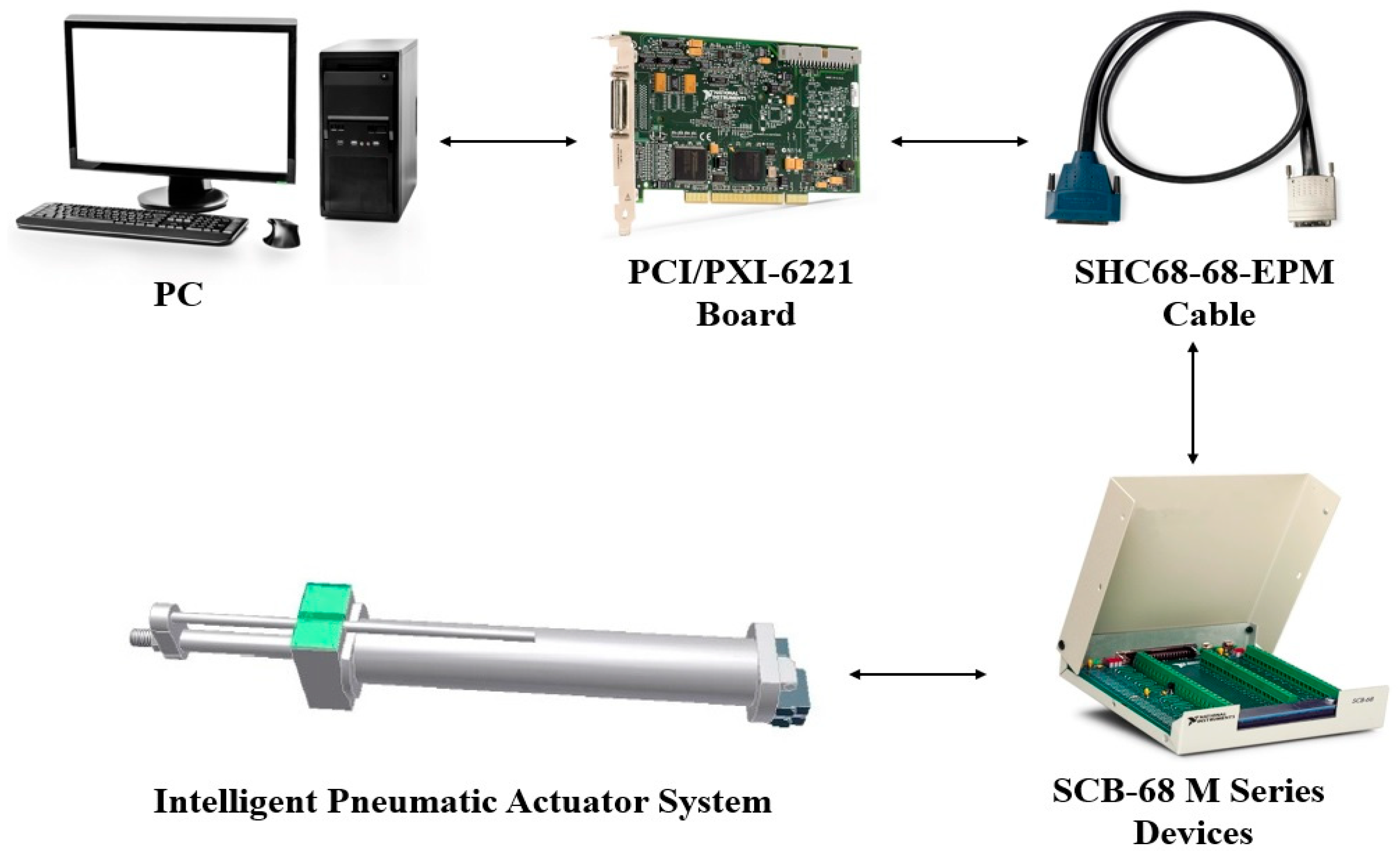
2.1.1. IPA Experimental Setup
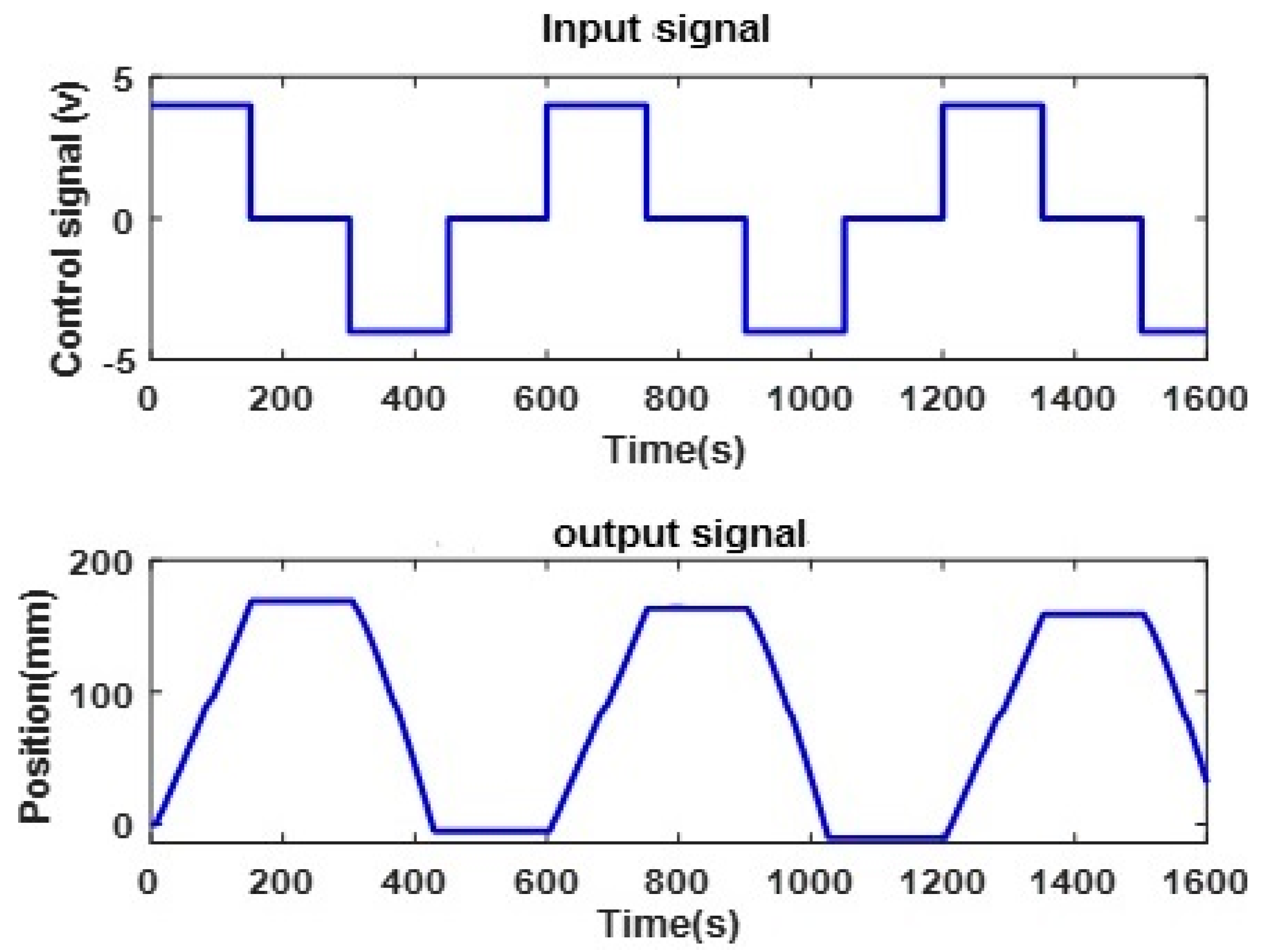
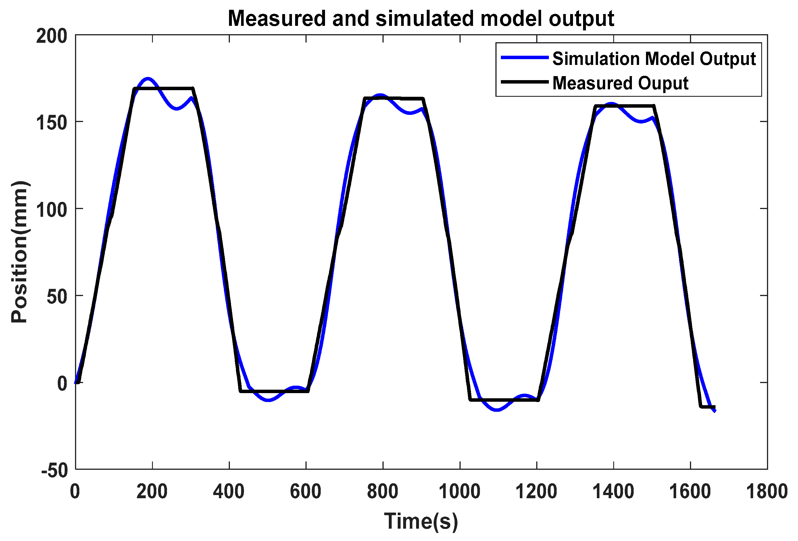
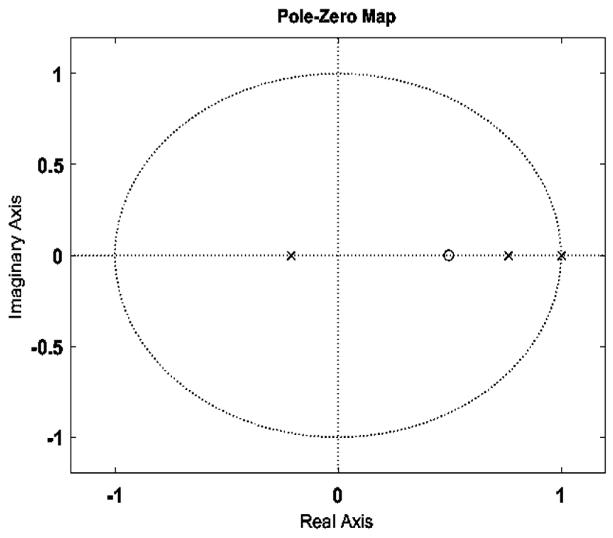
2.1.2. System Identification of IPA
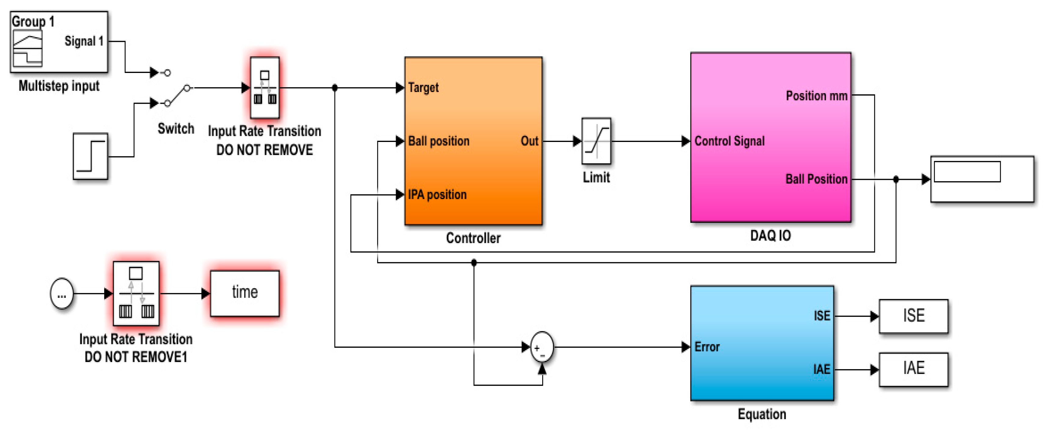
2.2. Pneumatic Actuated Ball and Beam (PABB) System
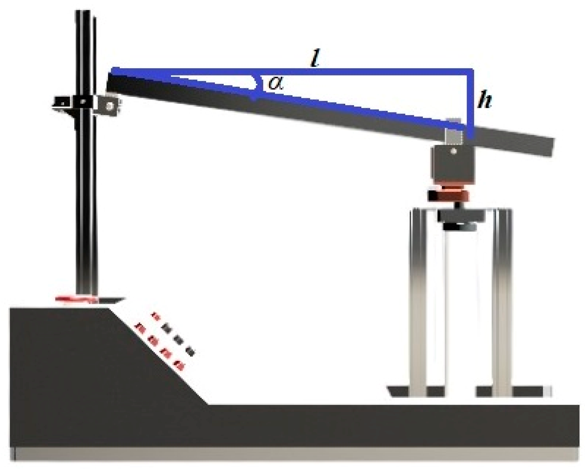
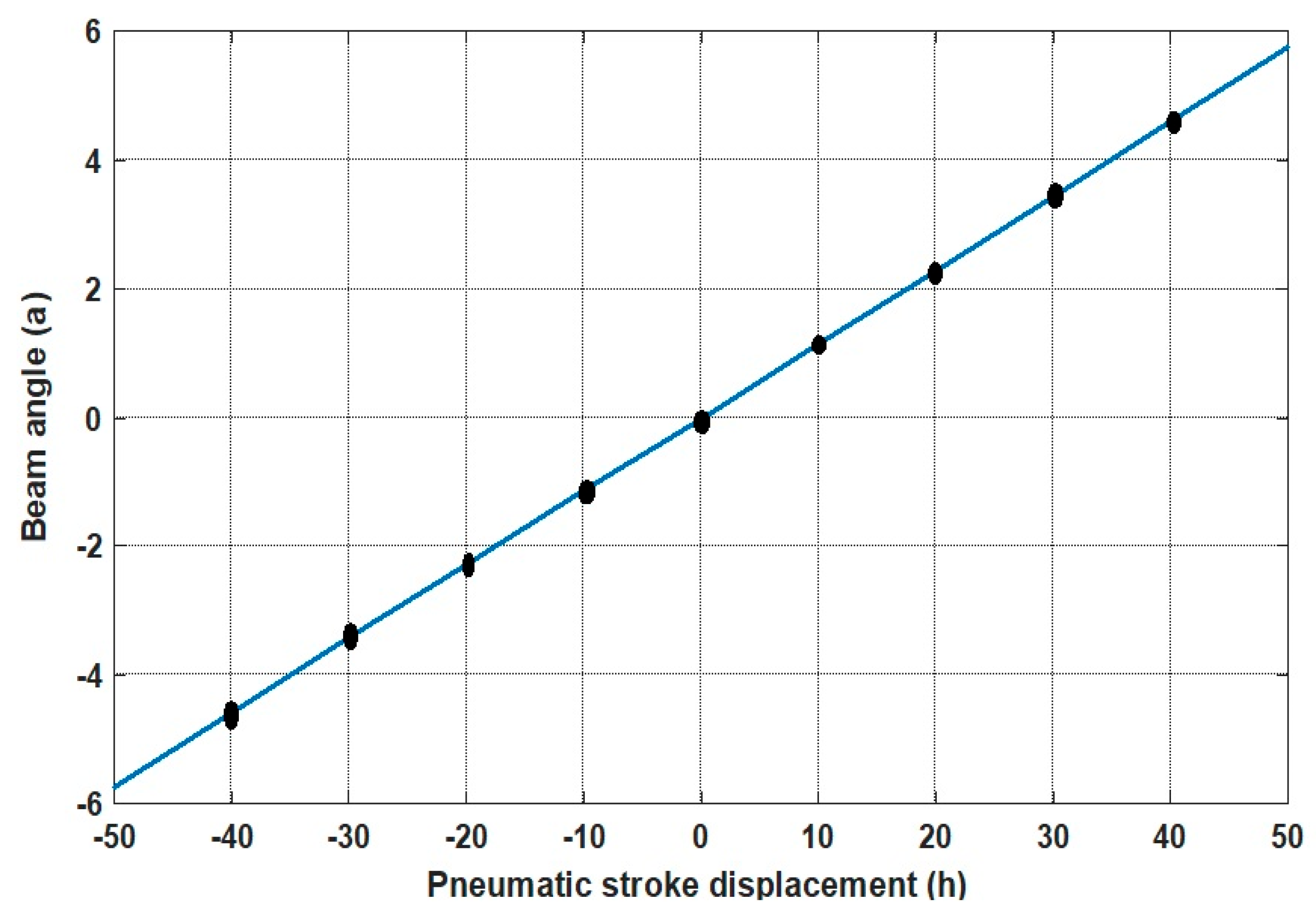
2.2.1. Mathematical Model of Pneumatic Actuated Ball and Beam (PABB) System
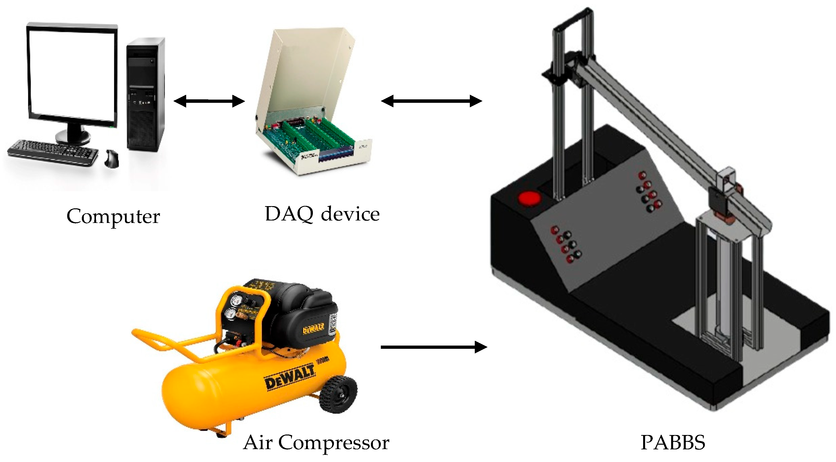
2.2.2. PABB Experimental Setup
3. Controller Design
3.1. Intelligent Pneumatic Actuator Controller Design—Inner Loop
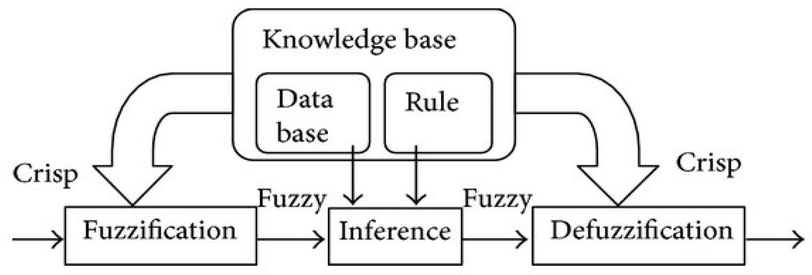
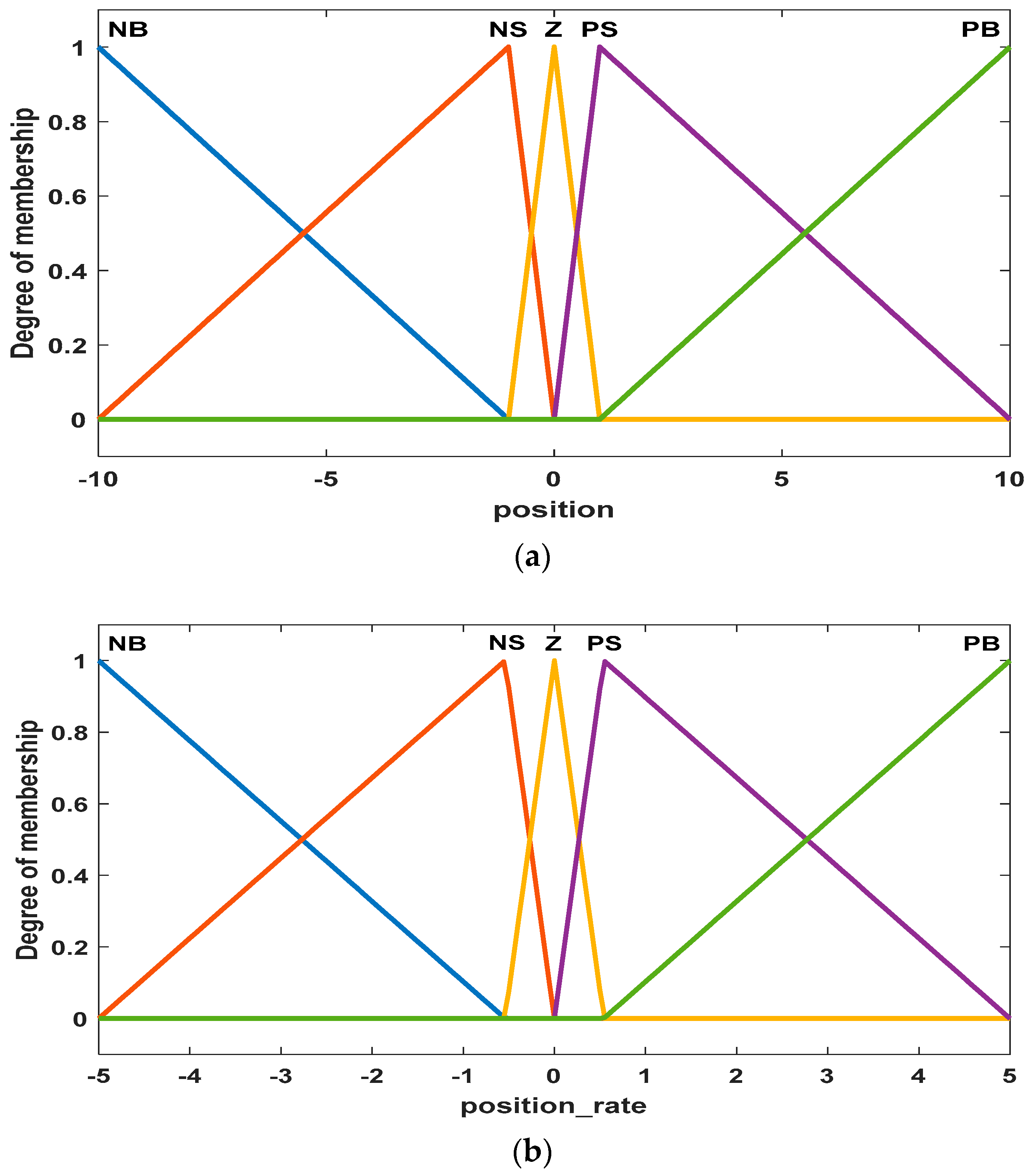
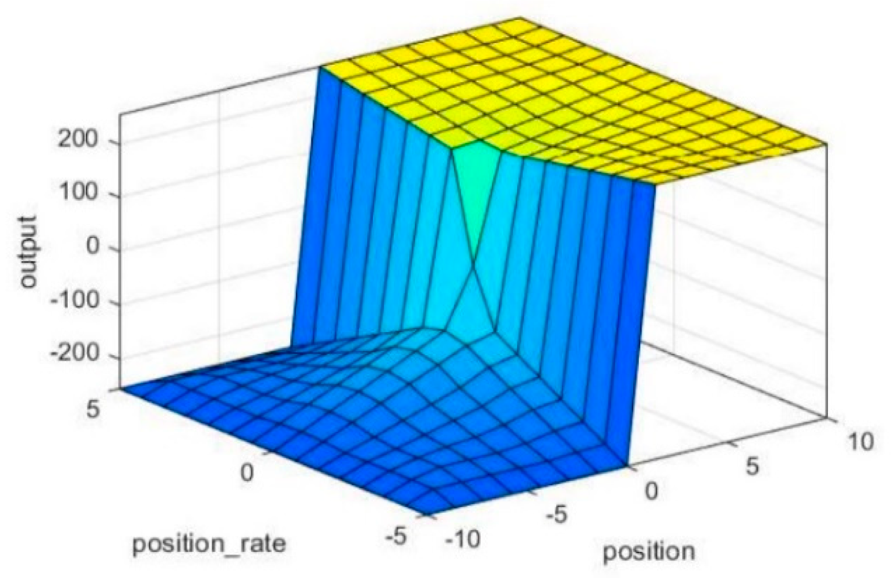
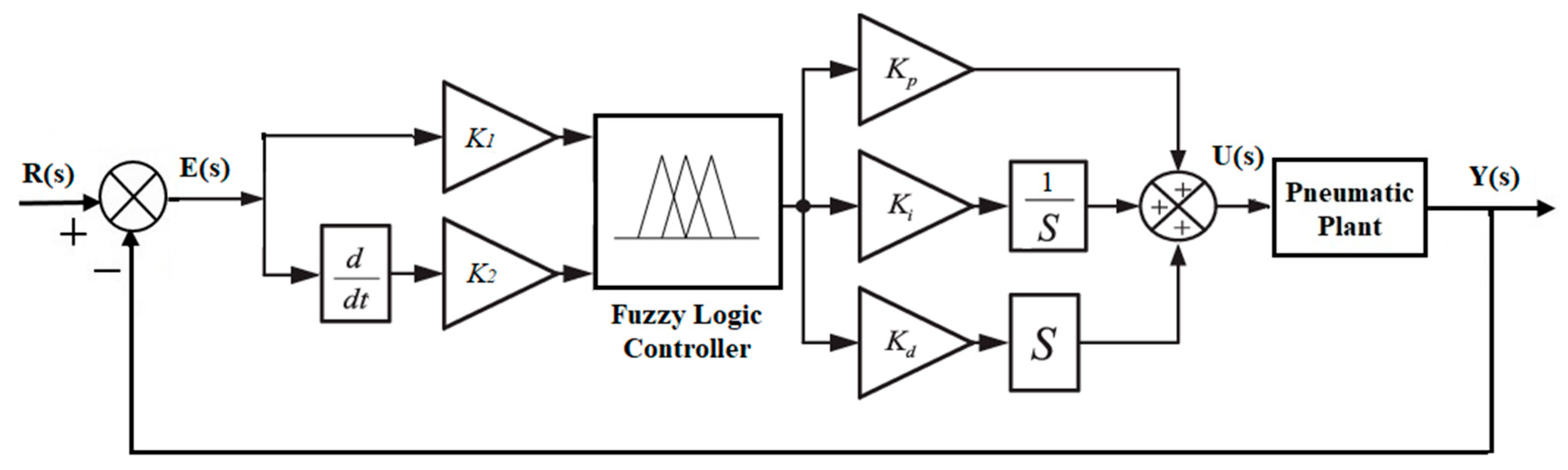
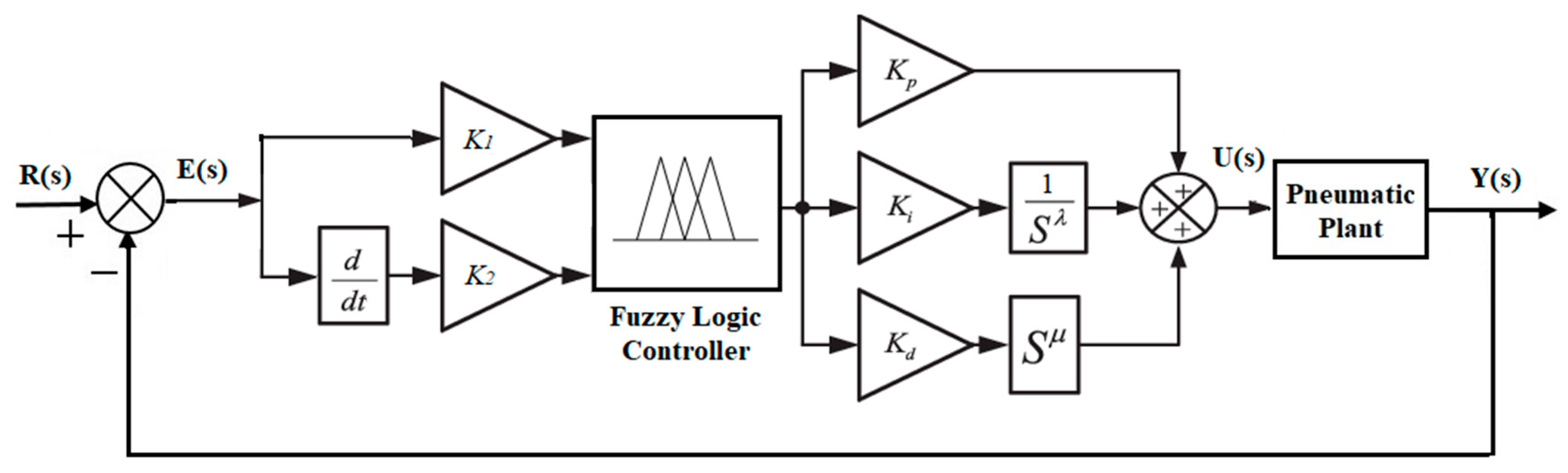
3.1.1. The Fuzzy PID (Fuzzy PID) Controller
3.1.2. The Fuzzy Fractional Order PID (Fuzzy FOPID) Controller
3.2. PABBS Controller Design—Outer Loop
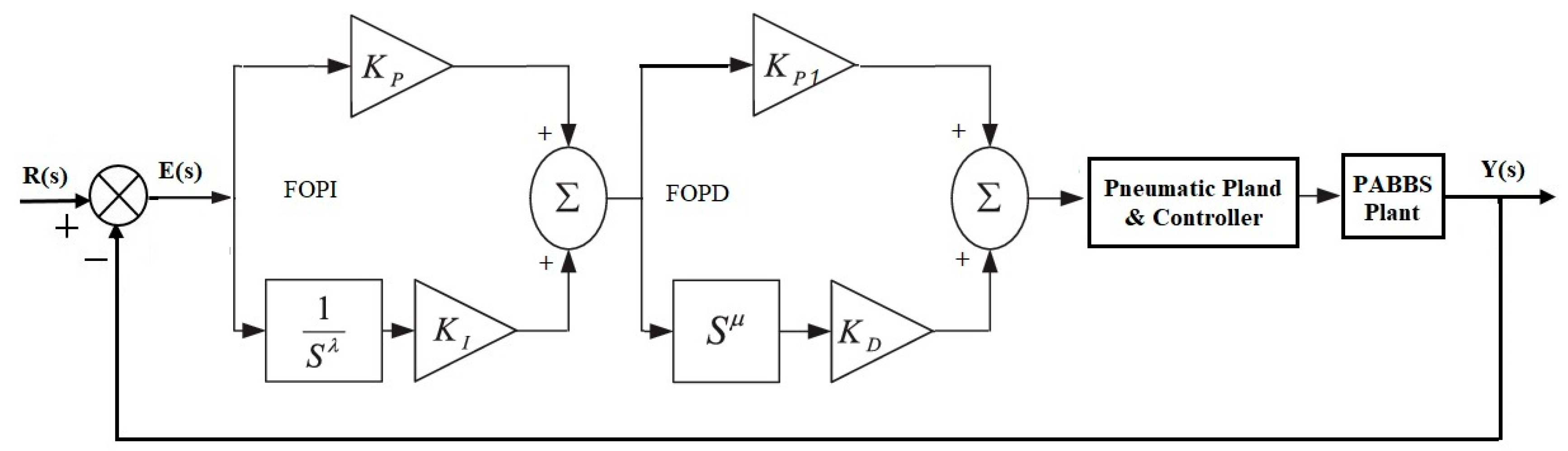
3.2.1. Fractional-Order PI–Fractional-Order PD (FOPI-FOPD) Controller Design
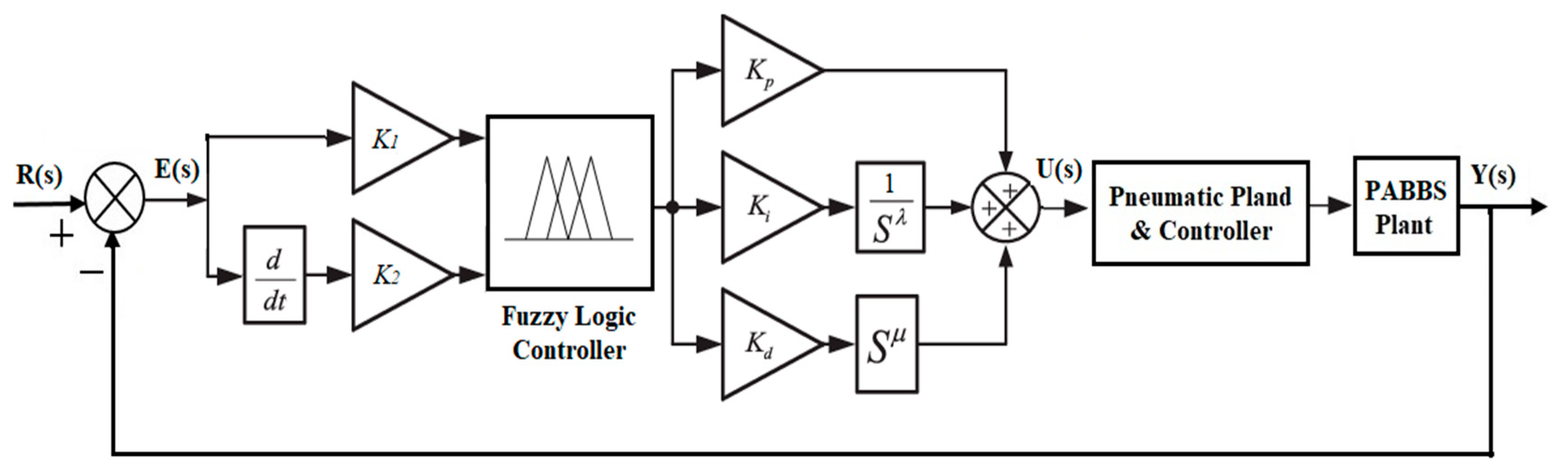
3.2.2. Cascade Fuzzy Fractional-Order PID (CFFOPID) Controller Design
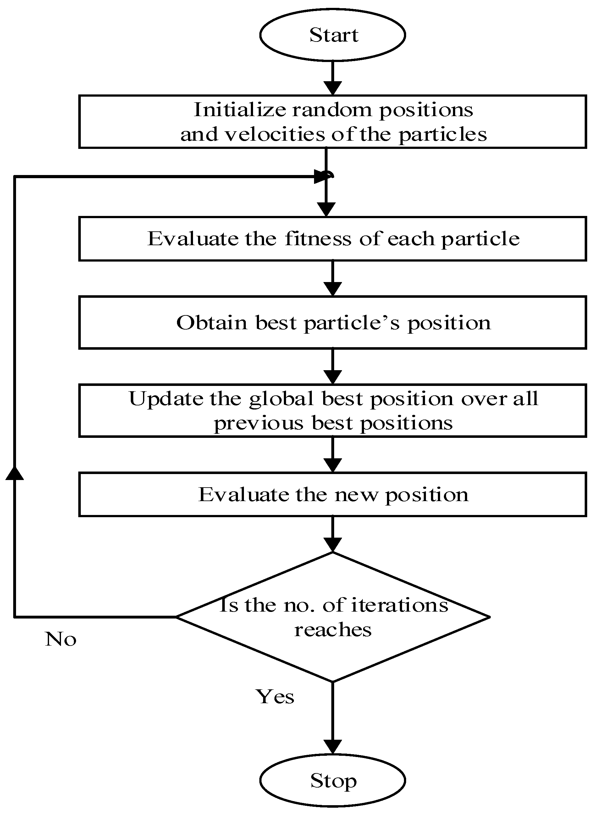
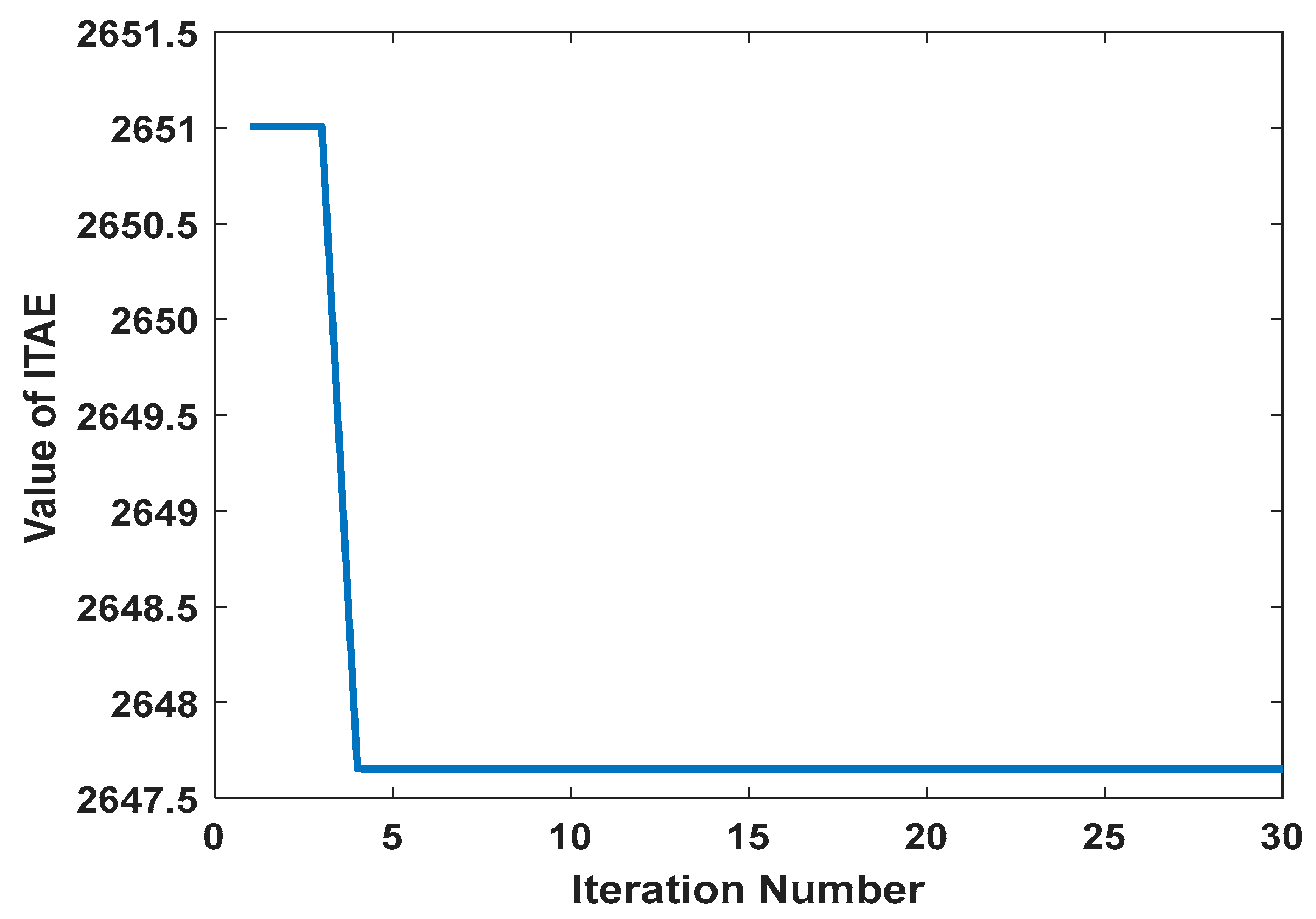
4. Particle Swarm Optimization Algorithm
5. Results and Discussion
5.1. Position Control for IPA System
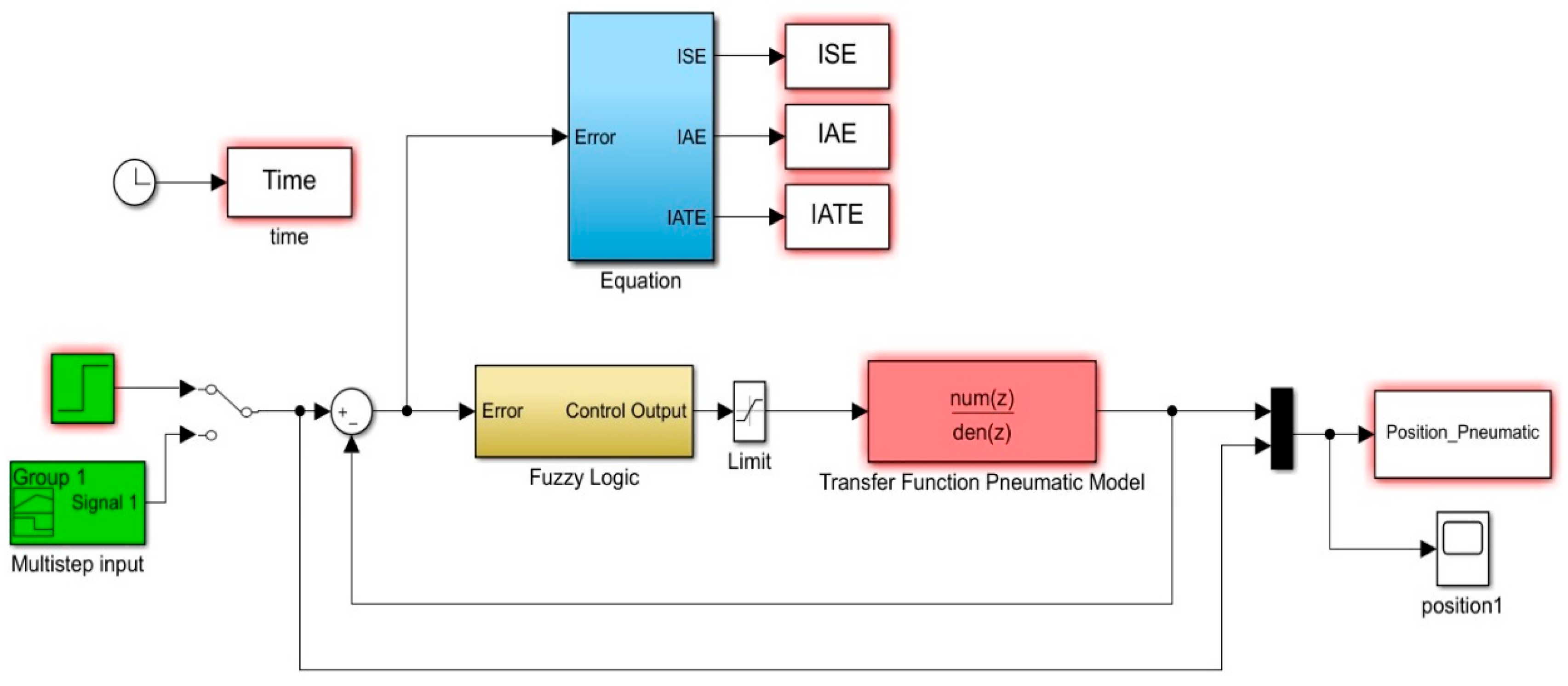
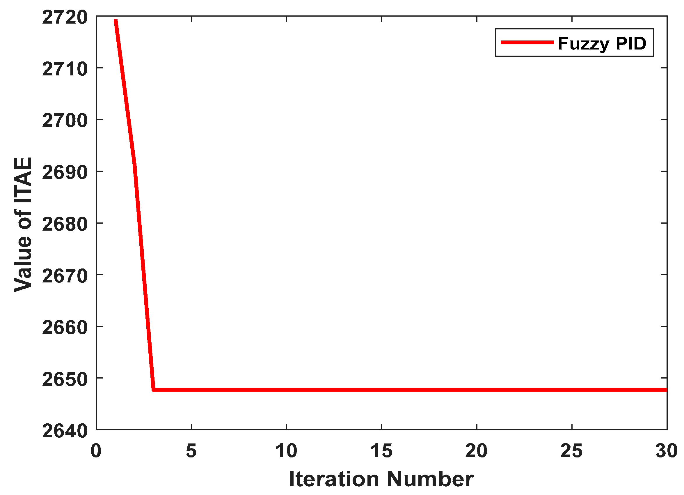
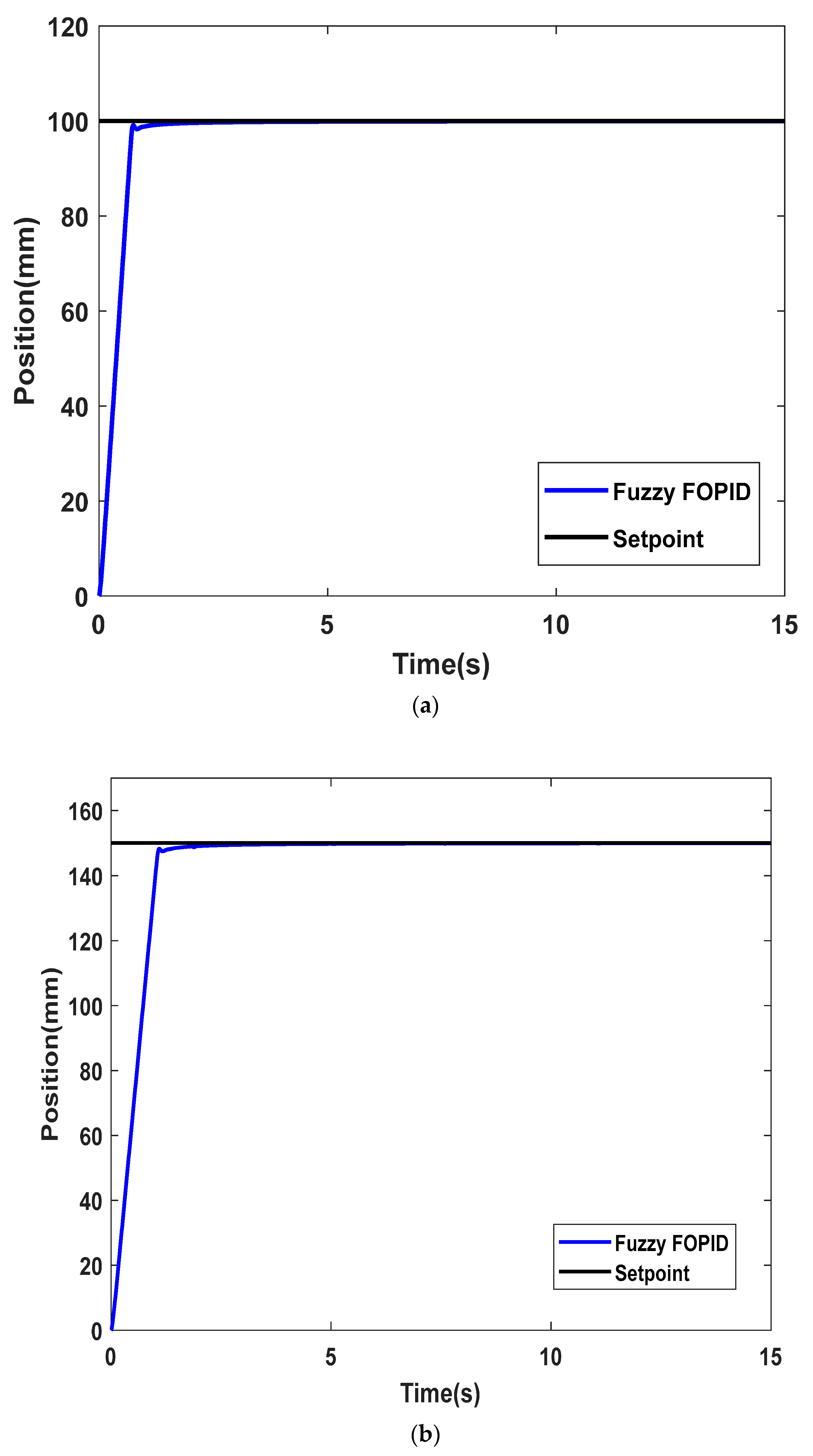
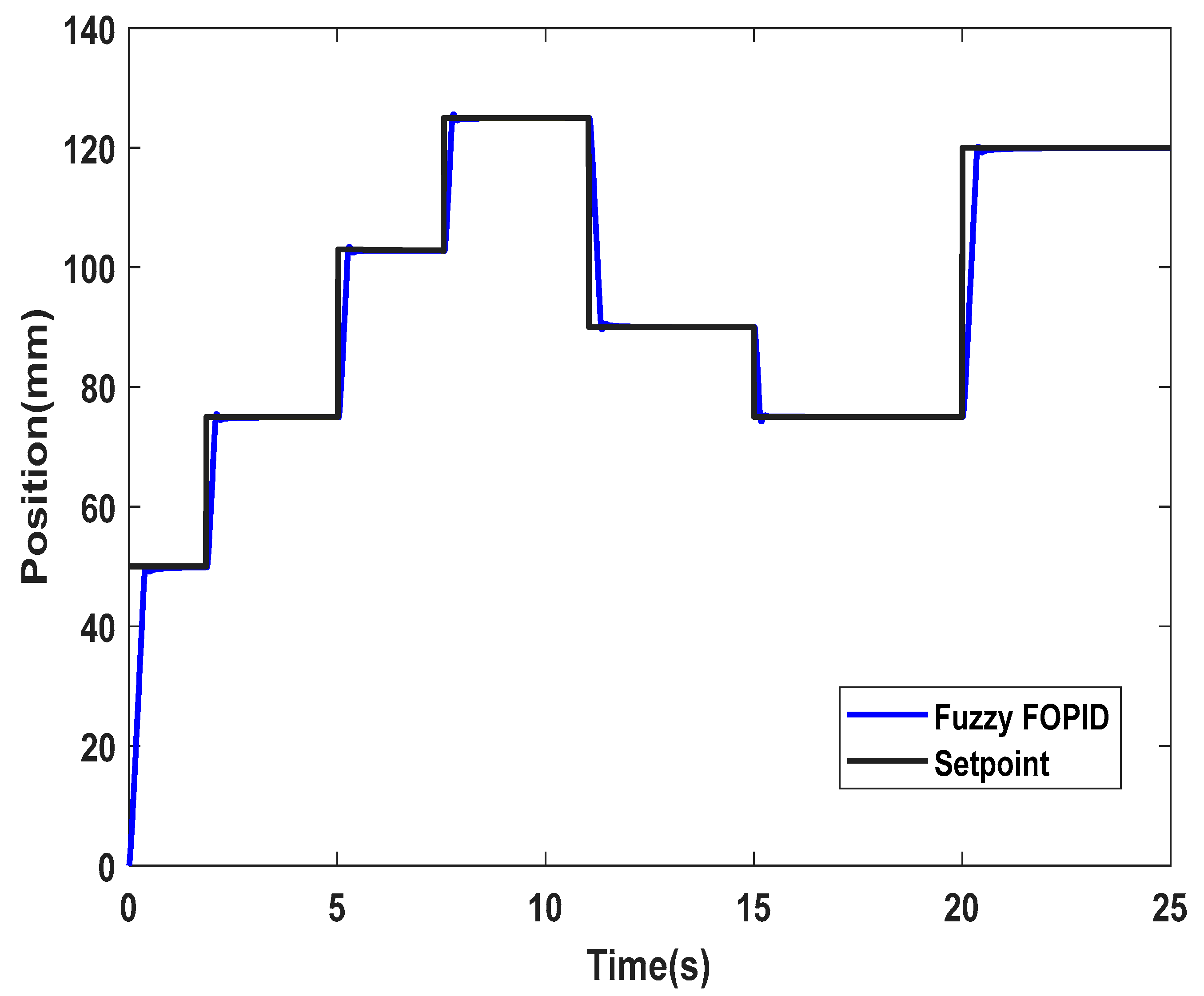
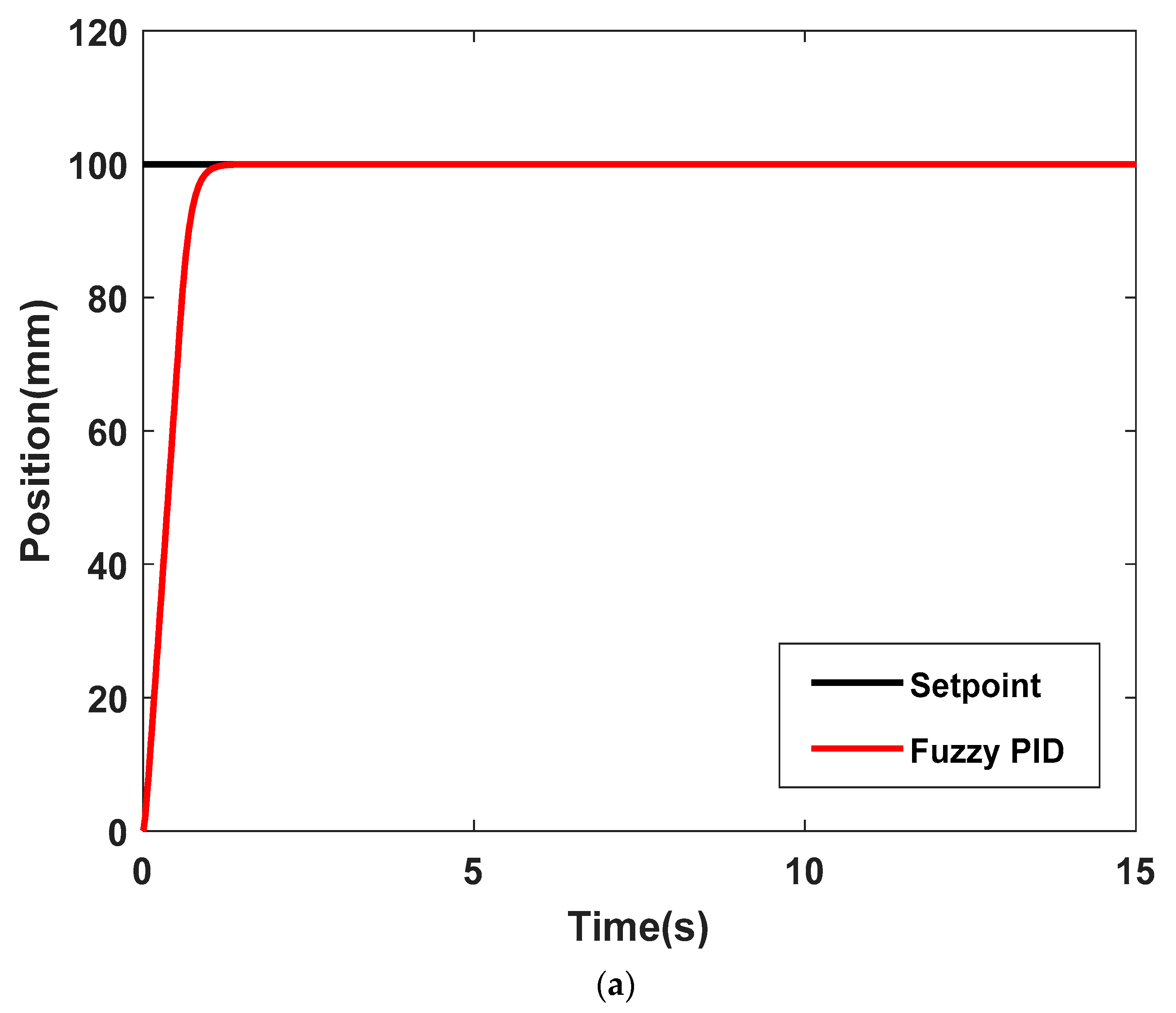
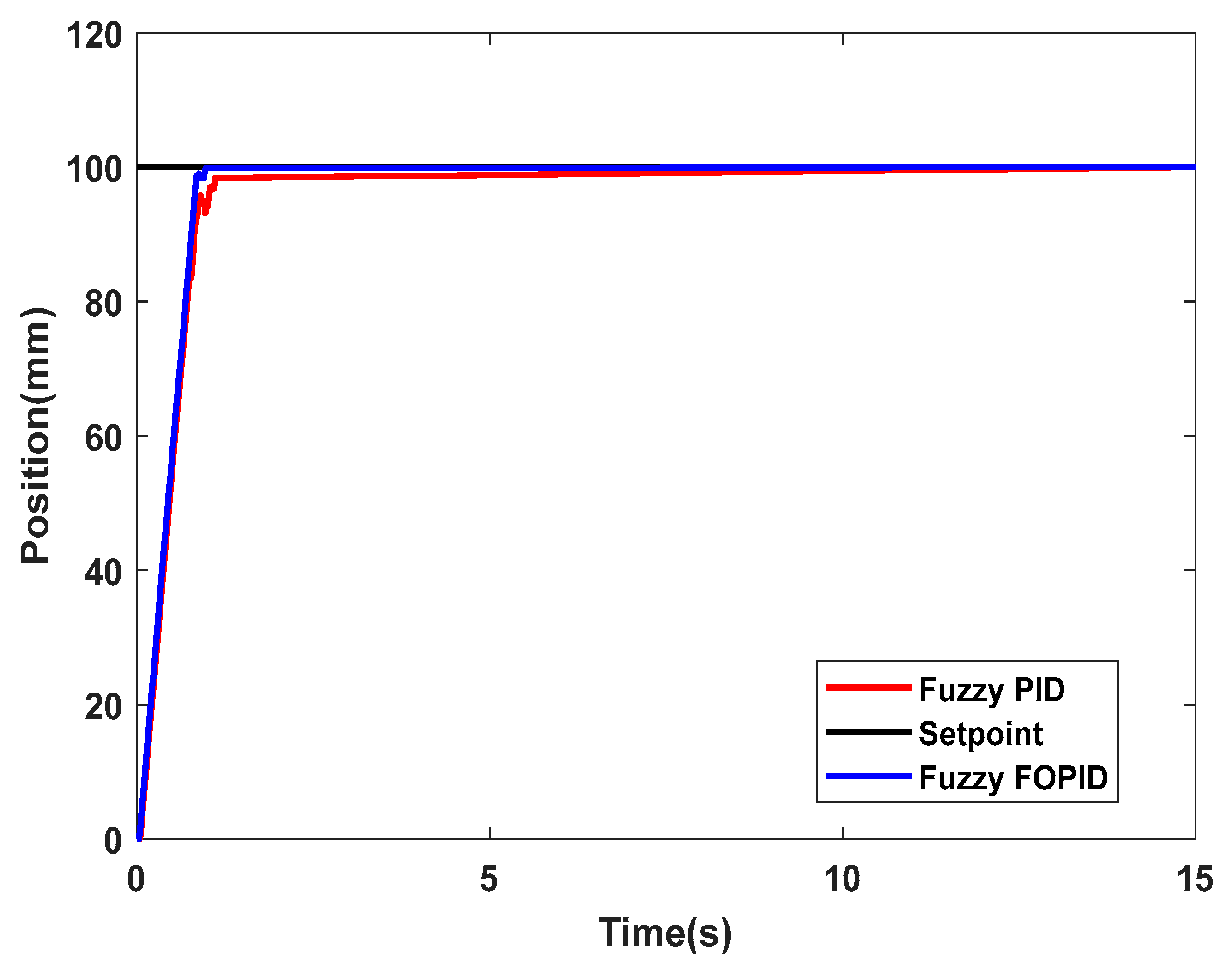
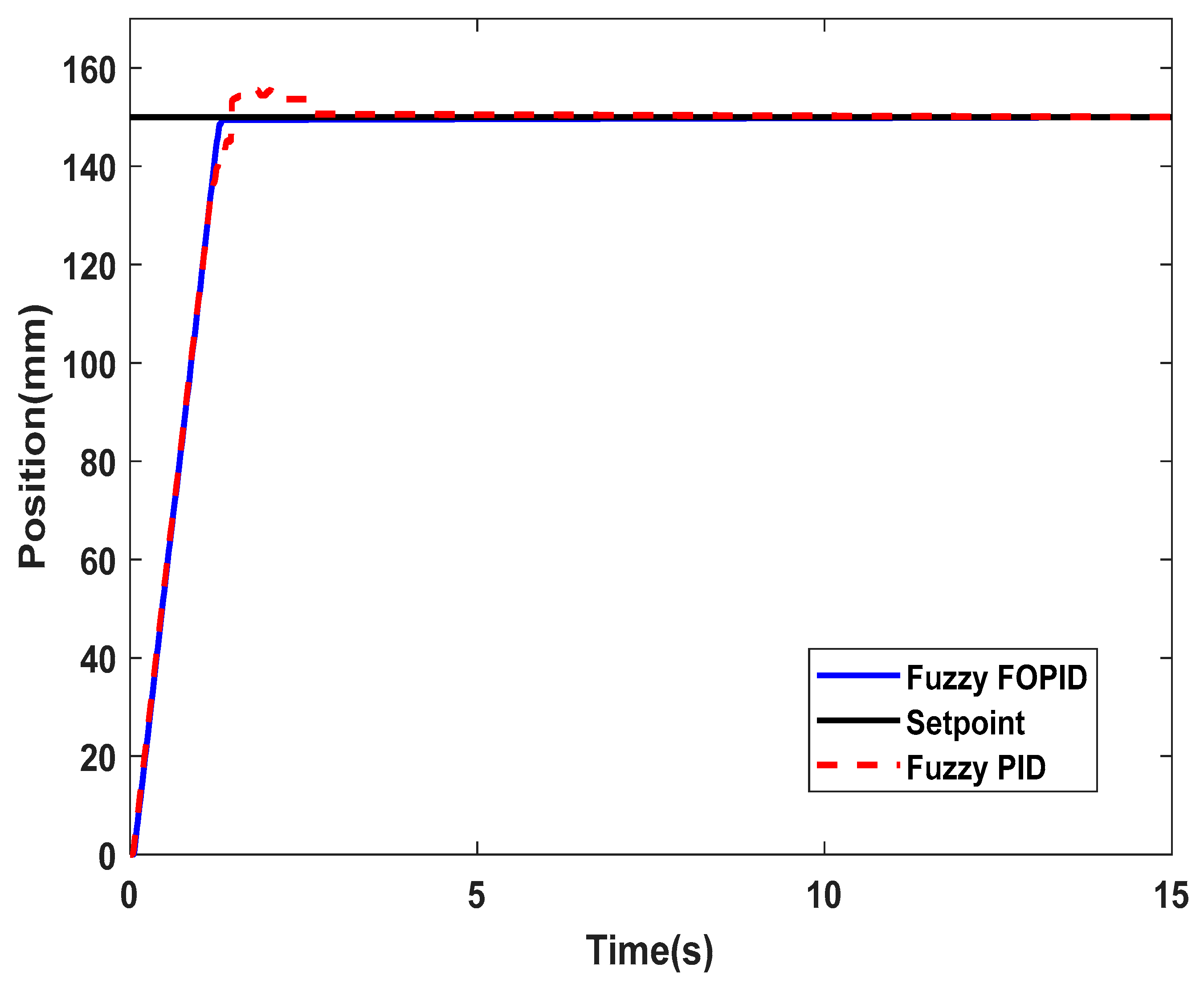
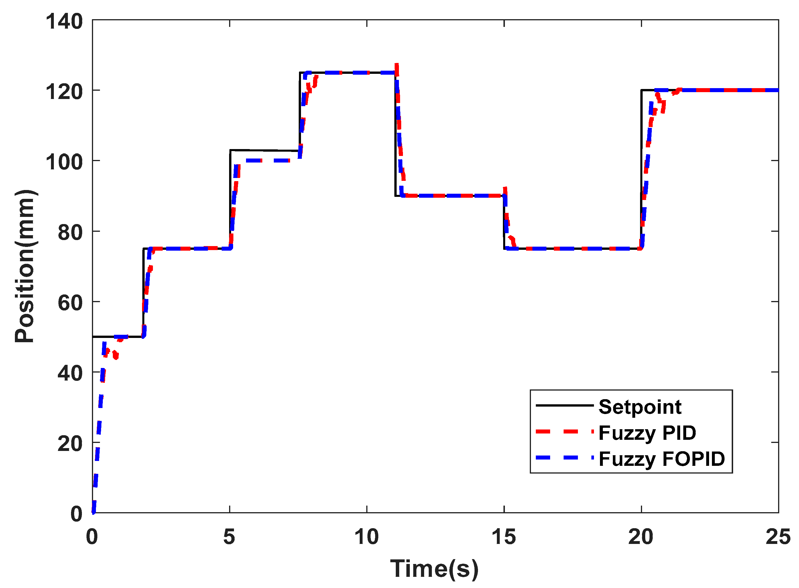
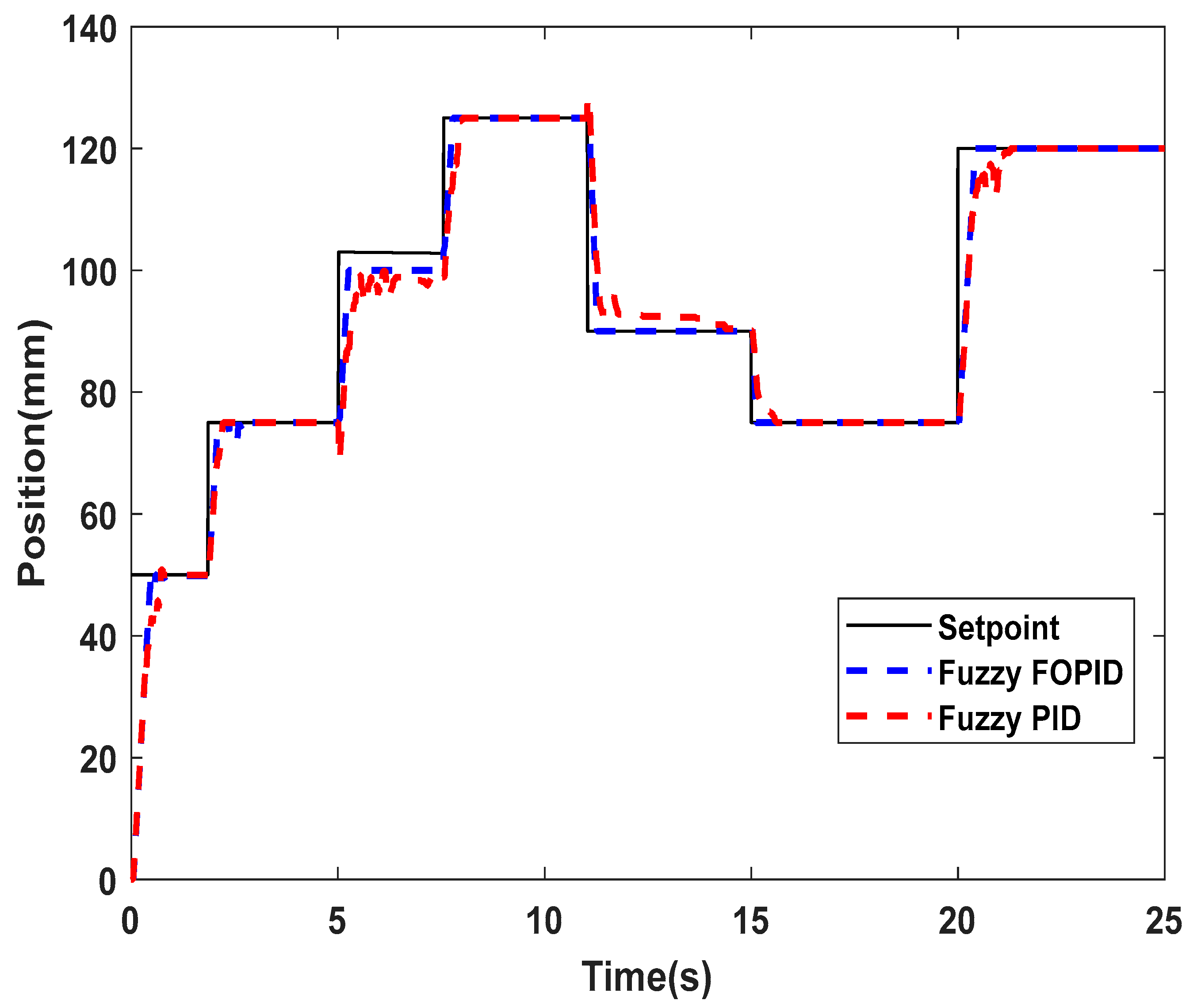
5.1.1. Simulation Performances of the IPA Positioning System
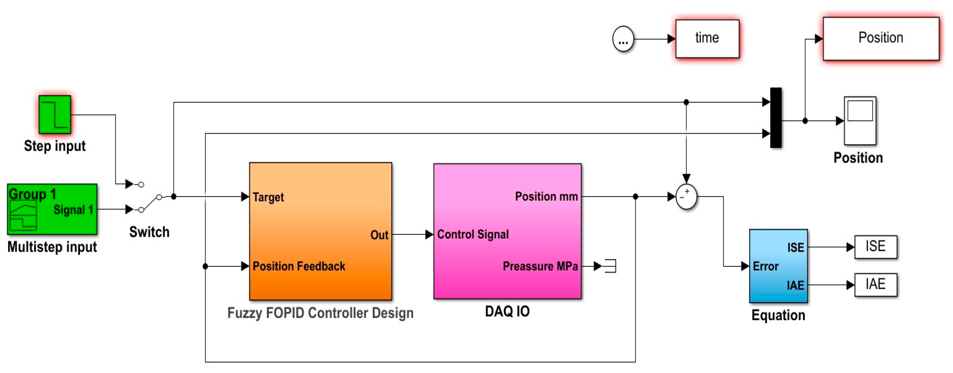
5.1.2. Experimental Validation Performances of the IPA Positioning System
5.2. PABB System Application Results
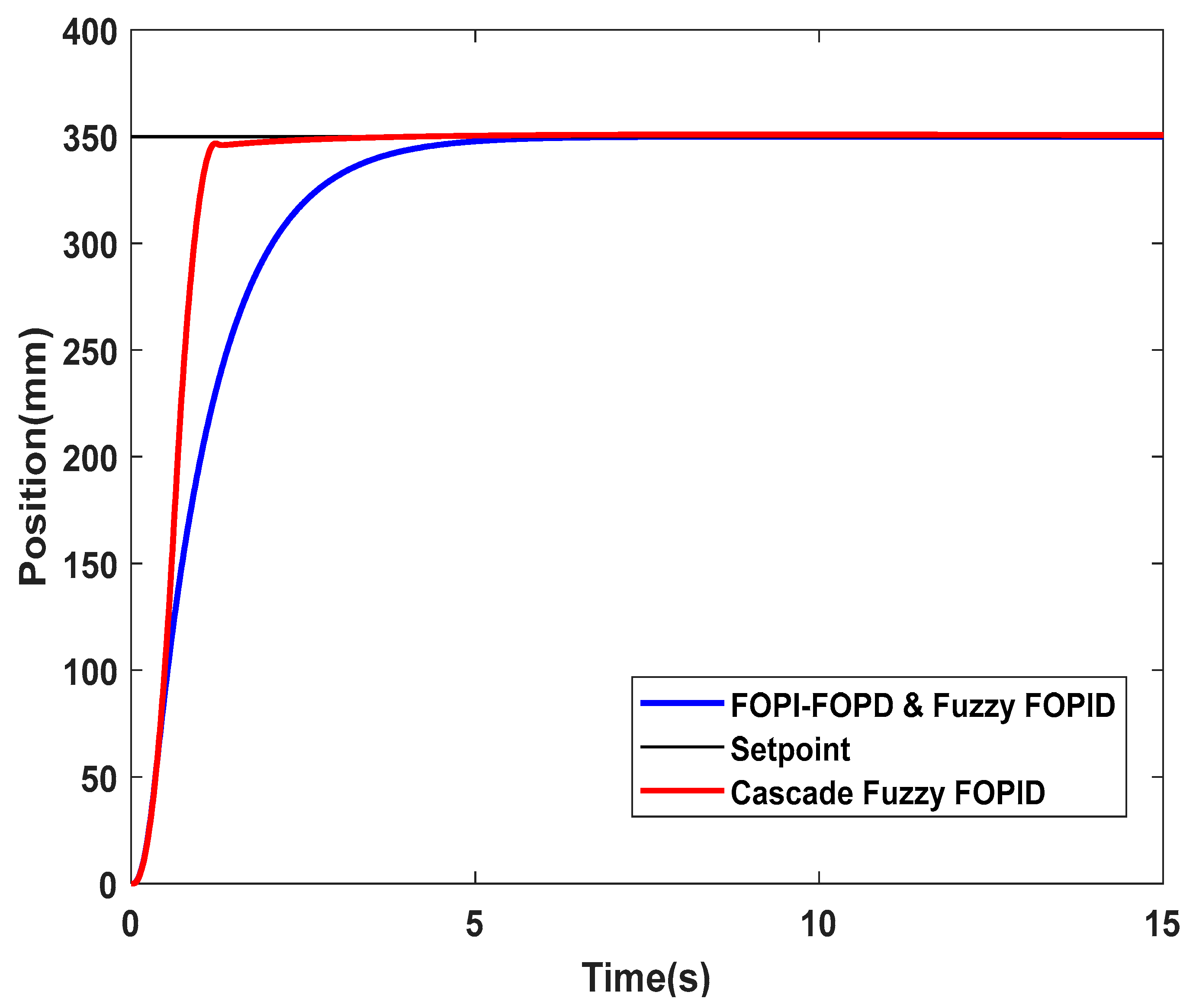
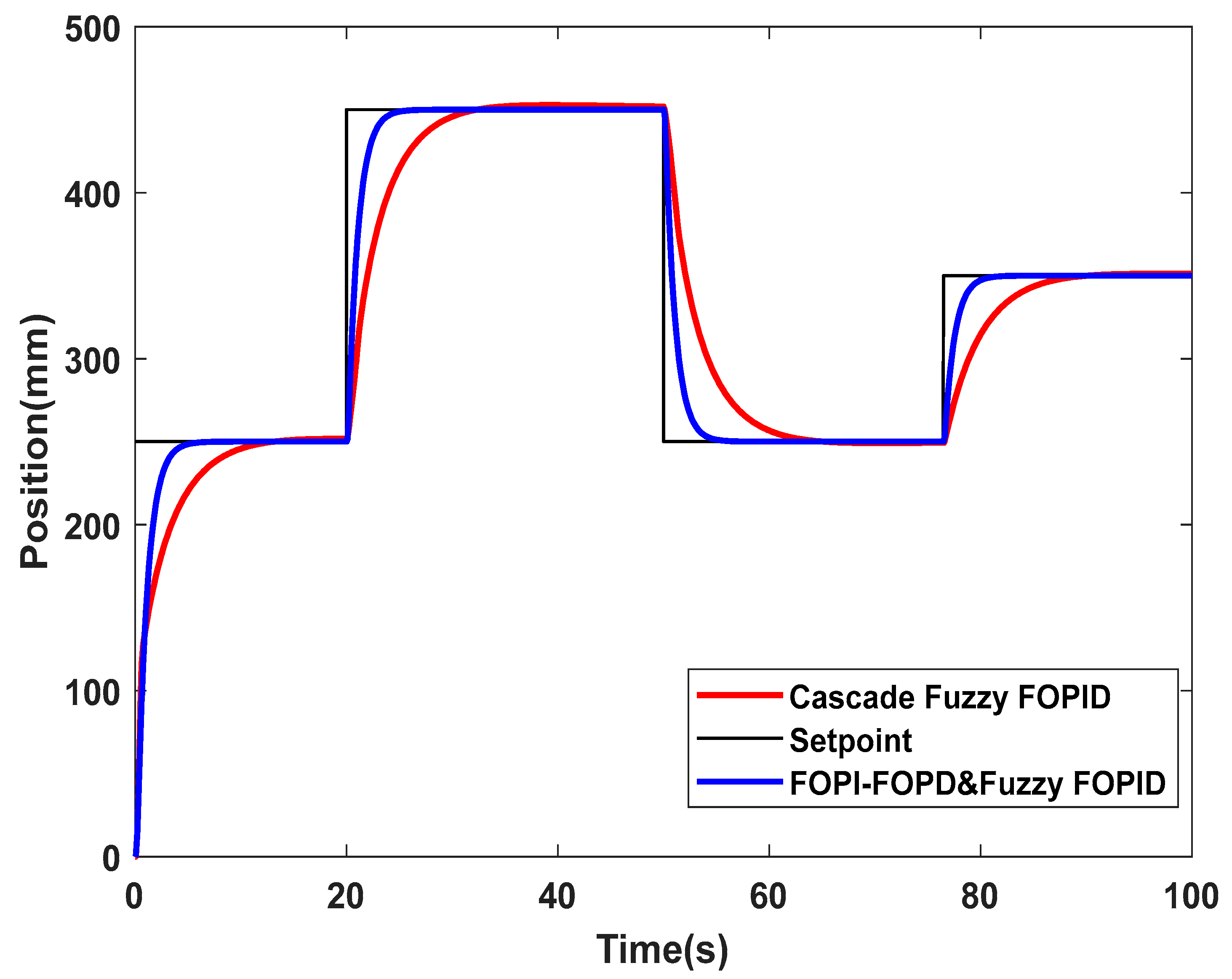
5.2.1. Simulation Performances of the PABB System
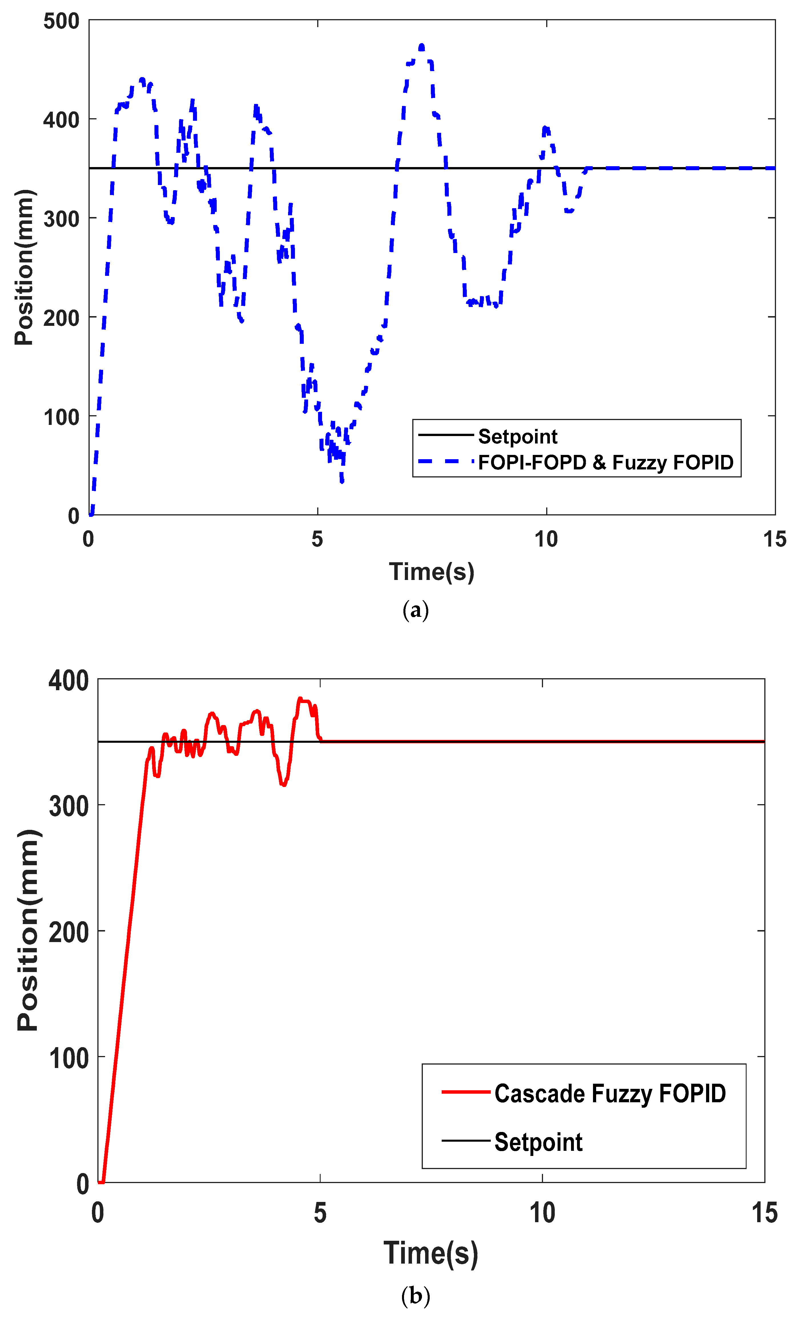
5.2.2. Experimental Validation Performances of the PABB System
6. Conclusions
Author Contributions
Funding
Data Availability Statement
Acknowledgments
Conflicts of Interest
References
- Van Varseveld, R.B.; Bone, G.M. Accurate position control of a pneumatic actuator using on/off solenoid valves. IEEE/ASME Trans. Mechatron. 1997, 2, 195–204. [Google Scholar] [CrossRef]
- Taghizadeh, M.; Najafi, F.; Ghaffari, A. Multimodel PD-control of a pneumatic actuator under variable loads. Int. J. Adv. Manuf. Technol. 2010, 48, 655–662. [Google Scholar] [CrossRef]
- Rahmat, M.F.; Salim, S.N.S.; Faudzi, A.A.M.; Ismail, Z.H.; Samsudin, S.I.; Sunar, N.H.; Jusoff, K. Non-linear modeling and cascade control of an industrial pneumatic actuator system. Aust. J. Basic Appl. Sci. 2011, 5, 465–477. [Google Scholar]
- Qian, P.; Pu, C.; Liu, L.; Lv, P.; Ruiz Páez, L.M. A novel pneumatic actuator based on high-frequency longitudinal vibration friction reduction. Sens. Actuators A Phys. 2022, 344, 113731. [Google Scholar] [CrossRef]
- Saravanakumar, D.; Mohan, B.; Muthuramalingam, T. A review on recent research trends in servo pneumatic positioning systems. Precis. Eng. 2017, 49, 481–492. [Google Scholar] [CrossRef]
- Faudzi, A.M.; Osman, K.; Rahmat, M.F.; Mustafa, N.D.; Azman, M.A.; Suzumori, K. Nonlinear mathematical model of an Intelligent Pneumatic Actuator (IPA) systems: Position and force controls. In Proceedings of the 2012 IEEE/ASME International Conference on Advanced Intelligent Mechatronics (AIM), Kaohsiung, Taiwan, 11–14 July 2012; pp. 1105–1110. [Google Scholar] [CrossRef]
- Chen, H.M.; Shyu, Y.P.; Chen, C.H. Design and Realization of a Sliding Mode Control Scheme for a Pneumatic Cylinder X-Y Axles Position Servo System. IET 2010, 416–421. [Google Scholar] [CrossRef]
- Muftah, M.N.; Xuan, W.L.; Athif, A.; Faudzi, M. ARX, ARMAX, Box-Jenkins, Output-Error, and Hammerstein Models for Modeling Intelligent Pneumatic Actuator (IPA) System. J. Integr. Adv. Eng. 2021, 1, 81–88. [Google Scholar] [CrossRef]
- Gentile, A.; Giannoccaro, N.I.; Reina, G. Experimental tests on position control of a pneumatic actuator using on/off solenoid valves. Proc. IEEE Int. Conf. Ind. Technol. 2002, 1, 555–559. [Google Scholar] [CrossRef]
- Osman, K.; Faudzi, A.A.M.; Rahmat, M.F.; Mustafa, N.D.; Abidin, A.F.Z.; Suzumori, K. Proportional-integrative controller design of Pneumatic system using particle swarm optimization. In Proceedings of the 2013 IEEE Student Conference on Research and Development, Putrajaya, Malaysia, 16–17 December 2013; pp. 421–426. [Google Scholar] [CrossRef]
- Tsai, Y.C.; Huang, A.C. Multiple-surface sliding controller design for pneumatic servo systems. Mechatronics 2008, 18, 506–512. [Google Scholar] [CrossRef]
- Azahar, M.I.P.; Irawan, A.; Ismail, R.M.T.R. Self-tuning hybrid fuzzy sliding surface control for pneumatic servo system positioning. Control Eng. Pract. 2021, 113, 104838. [Google Scholar] [CrossRef]
- Schindele, D.; Aschemann, H. Adaptive friction compensation based on the LuGre model for a pneumatic rodless cylinder. In Proceedings of the 2009 35th Annual Conference of IEEE Industrial Electronics, Porto, Portugal, 3–5 November 2009; pp. 1432–1437. [Google Scholar] [CrossRef]
- Azman, M.A.; Osman, K.; Natarajan, E. Integrating Servo-Pneumatic Actuator with Ball Beam System based on intelligent position control. J. Teknol. 2014, 3, 73–79. [Google Scholar] [CrossRef]
- Mu, S.; Goto, S.; Shibata, S.; Yamamoto, T. Intelligent position control for pneumatic servo system based on predictive fuzzy control. Comput. Electr. Eng. 2019, 75, 112–122. [Google Scholar] [CrossRef]
- Osman, K.; Faudzi, A.; Athif, M.; Rahmat, M.F.; Hikmat, O.F.; Suzumori, K. Predictive Functional Control with Observer (PFC-O) Design and Loading Effects Performance for a Pneumatic System. Arab. J. Sci. Eng. 2015, 40, 633–643. [Google Scholar] [CrossRef]
- Muftah, M.N.; Athif, A.; Faudzi, M.; Sahlan, S.; Shouran, M. Modeling and Fuzzy FOPID Controller Tuned by PSO for Pneumatic Positioning System. Energies 2022, 15, 3757. [Google Scholar] [CrossRef]
- Podlubny, I. Fractional-order systems and PIλDµ controllers. IEEE Trans. Automat. Contr. 1999, 44, 208–214. [Google Scholar] [CrossRef]
- Sikander, A.; Thakur, P.; Bansal, R.C.; Rajasekar, S. A novel technique to design cuckoo search based FOPID controller for AVR in power systems. Comput. Electr. Eng. 2018, 70, 261–274. [Google Scholar] [CrossRef]
- Rajasekhar, A.; Kumar Jatoth, R.; Abraham, A. Design of intelligent PID/PIλDμ speed controller for chopper fed DC motor drive using opposition based artificial bee colony algorithm. Eng. Appl. Artif. Intell. 2014, 29, 13–32. [Google Scholar] [CrossRef]
- Dumlu, A.; Erenturk, K. Trajectory tracking control for a 3-DOF parallel manipulator using fractional-order PIλDμ control. IEEE Trans. Ind. Electron. 2014, 61, 3417–3426. [Google Scholar] [CrossRef]
- Luo, Y.; Chen, Y. Stabilizing and robust fractional order PI controller synthesis for first order plus time delay systems. Automatica 2012, 48, 2159–2167. [Google Scholar] [CrossRef]
- Altintas, G.; Aydin, Y. Optimization of Fractional and Integer Order PID Parameters using Big Bang Big Crunch and Genetic Algorithms for a MAGLEV System. IFAC-PapersOnLine 2017, 50, 4881–4886. [Google Scholar] [CrossRef]
- Karahan, O. Design of optimal fractional order fuzzy PID controller based on cuckoo search algorithm for core power control in molten salt reactors. Prog. Nucl. Energy 2021, 139, 103868. [Google Scholar] [CrossRef]
- Fu, W.; Wang, K.; Li, C.; Tan, J. Multi-step short-term wind speed forecasting approach based on multi-scale dominant ingredient chaotic analysis, improved hybrid GWO-SCA optimization and ELM. Energy Convers. Manag. 2019, 187, 356–377. [Google Scholar] [CrossRef]
- Altbawi, S.M.A.; Mokhtar, A.S.B.; Jumani, T.A.; Khan, I.; Hamadneh, N.N.; Khan, A. Optimal design of Fractional order PID controller based Automatic voltage regulator system using gradient-based optimization algorithm. J. King Saud Univ.—Eng. Sci. 2021, in press. [Google Scholar] [CrossRef]
- Shouran, M.; Alsseid, A. Particle Swarm Optimization Algorithm-Tuned Fuzzy Cascade Fractional Order PI-Fractional Order PD for Frequency Regulation of Dual-Area Power System. Processes 2022, 10, 477. [Google Scholar] [CrossRef]
- Rajesh, R. Optimal tuning of FOPID controller based on PSO algorithm with reference model for a single conical tank system. SN Appl. Sci. 2019, 1, 1–14. [Google Scholar] [CrossRef]
- Bingul, Z.; Karahan, O. Comparison of PID and FOPID controllers tuned by PSO and ABC algorithms for unstable and integrating systems with time delay. Optim. Control Appl. Methods 2018, 39, 1431–1450. [Google Scholar] [CrossRef]
- Osinski, C.; Silveira, A.L.R.; Stiegelmaier, C.; Bergamini, M.G.; Leandro, G.V. Control of ball and beam system using fuzzy PID controller. In Proceedings of the 2018 13th IEEE International Conference on Industry Applications (INDUSCON), Sao Paulo, Brazil, 12–14 November 2018; pp. 875–880. [Google Scholar] [CrossRef]
- Šitum, Ž.; Trslić, P. Ball and beam balancing mechanism actuated with pneumatic artificial muscles. J. Mech. Robot. 2018, 10, 055001. [Google Scholar] [CrossRef]
- Hannan, M.A.; Ghani, Z.A.; Hoque, M.M.; Ker, P.J.; Hussain, A.; Mohamed, A. Fuzzy logic inverter controller in photovoltaic applications: Issues and recommendations. IEEE Access 2019, 7, 24934–24955. [Google Scholar] [CrossRef]
- El Ouanjli, N.; Motahhir, S.; Derouich, A.; El Ghzizal, A.; Chebabhi, A.; Taoussi, M. Improved DTC strategy of doubly fed induction motor using fuzzy logic controller. Energy Rep. 2019, 5, 271–279. [Google Scholar] [CrossRef]
- Kennedy, J.; Eberhart, R. Particle Swarm Optimisation. In Proceedings of the ICNN’95—International Conference on Neural Networks, Perth, WA, Australia, 27 November–1 December 1995; pp. 1942–1948. [Google Scholar] [CrossRef]
- Shi, Y.; Eberhart, R. A Modified Particle Swarm Optimizer. In Proceedings of the 1998 IEEE International Conference on Evolutionary Computation Proceedings, IEEE World Congress on Computational Intelligence (Cat. No.98TH8360), Anchorage, AK, USA, 4–9 May 1998; pp. 69–73. [Google Scholar] [CrossRef]
- Solihin, M.I.; Tack, L.F.; Kean, M.L. Tuning of PID Controller Using Particle Swarm Optimization (PSO). Int. J. Adv. Sci. Eng. Inf. Technol. 2011, 1, 458. [Google Scholar] [CrossRef]
- Mishra, A.K.; Das, S.R.; Ray, P.K.; Mallick, R.K.; Mohanty, A.; Mishra, D.K. PSO-GWO Optimized Fractional Order PID Based Hybrid Shunt Active Power Filter for Power Quality Improvements. IEEE Access 2020, 8, 74497–74512. [Google Scholar] [CrossRef]
- Shouran, M.; Anayi, F.; Packianather, M.; Habil, M. Different Fuzzy Control Configurations Tuned by the Bees Algorithm for LFC of Two-Area Power System. Energies 2022, 15, 657. [Google Scholar] [CrossRef]


| Quantity | Value |
|---|---|
| Beam Length (l) | 0.5 m |
| Pneumatic Actuator Stroke Length (h) | 0–200 mm |
| Angle (α) | Depends on h |
| The Ball Mass (m) | 0.04012 kg |
| The Ball Radius (R) | 0.0107 m |
| Ball’s Moment of Inertia (J) | |
| Gravitational Acceleration (g) |
| Error rate, ∆e(t) | Error, e(t) | ||||
| NB | NS | Z | PS | PB | |
| NB | NB | NB | NB | PB | PB |
| NB | NB | NS | NS | PS | PB |
| NB | NB | NS | Z | PS | PB |
| NB | NB | NS | PS | PS | PB |
| NB | NB | NB | PB | PB | PB |
| Parameter | No. Iteration | No. Particles | Social Coefficient | Cognitive Coefficient | Inertia Weight |
|---|---|---|---|---|---|
| Value | 30 | 10 | 1.42 | 1.42 | 0.9 |
| Criteria | K1 | K2 | Kp | Ki | λ | Kd | µ |
|---|---|---|---|---|---|---|---|
| Fuzzy FOPID | 0.0001 | 0.0495 | 25 | 1 | 0.1 | 10 | 0.1 |
| Fuzzy PID | 0.0002 | 0.05 | 25 | 0.1 | - | 1 | - |
| Distance (mm) | Transient Performance | Fuzzy FOPID | Fuzzy PID |
|---|---|---|---|
| 100 | Tr (s) | 0.5616 | 0.6953 |
| Ts (s) | 0.7188 | 1.0349 | |
| OS (%) | 0 | 0.00022 | |
| ess | 0 | 0 | |
| 150 | Tr (s) | 0.8400 | 0.9510 |
| Ts (s) | 1.0602 | 1.2002 | |
| OS (%) | 0 | 0.00031 | |
| ess | 0 | 0 |
| Distance (mm) | Transient Performance | Fuzzy FOPID | Fuzzy PID |
|---|---|---|---|
| 100 | Tr (s) | 0.6577 | 0.7418 |
| Ts (s) | 0.9544 | 1.0337 | |
| OS (%) | 0 | 0.00022 | |
| ess | 0 | 0 | |
| 150 | Tr (s) | 1.0468 | 1.0301 |
| Ts (s) | 1.3497 | 1.3741 | |
| OS (%) | 0 | 0.00031 | |
| ess | 0 | 0 |
| Distance (mm) | Transient Performance | Fuzzy FOPID | Fuzzy PID |
|---|---|---|---|
| 100 | Tr (s) | 0.6372 | 0.7306 |
| Ts (s) | 0.8381 | 1.1076 | |
| OS (%) | 0 | 0.00022 | |
| ess | 0 | 0 | |
| 150 | Tr (s) | 0.9874 | 1.0196 |
| Ts (s) | 1.2726 | 1.5662 | |
| OS (%) | 0 | 0.00031 | |
| ess | 0 | 0 |
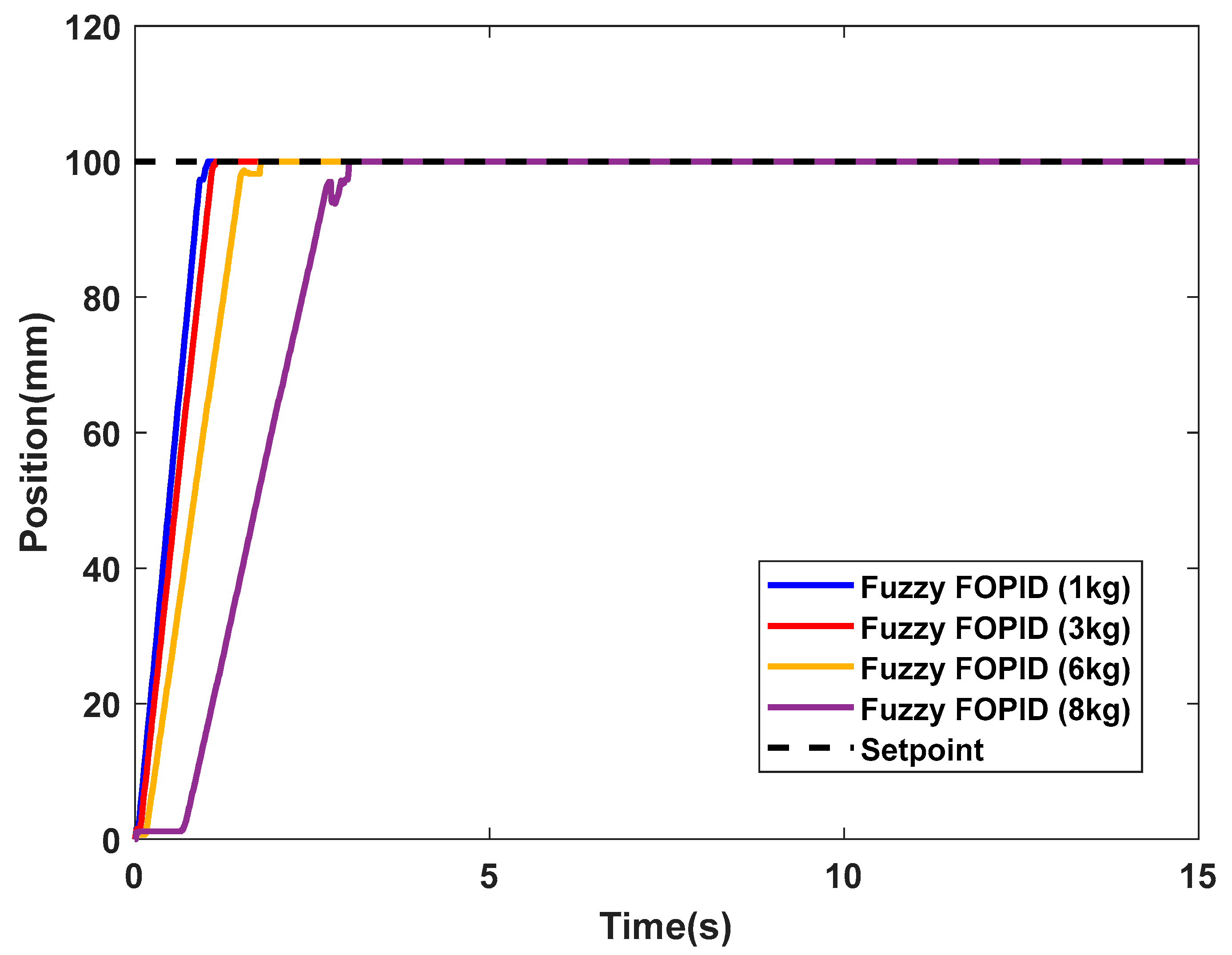
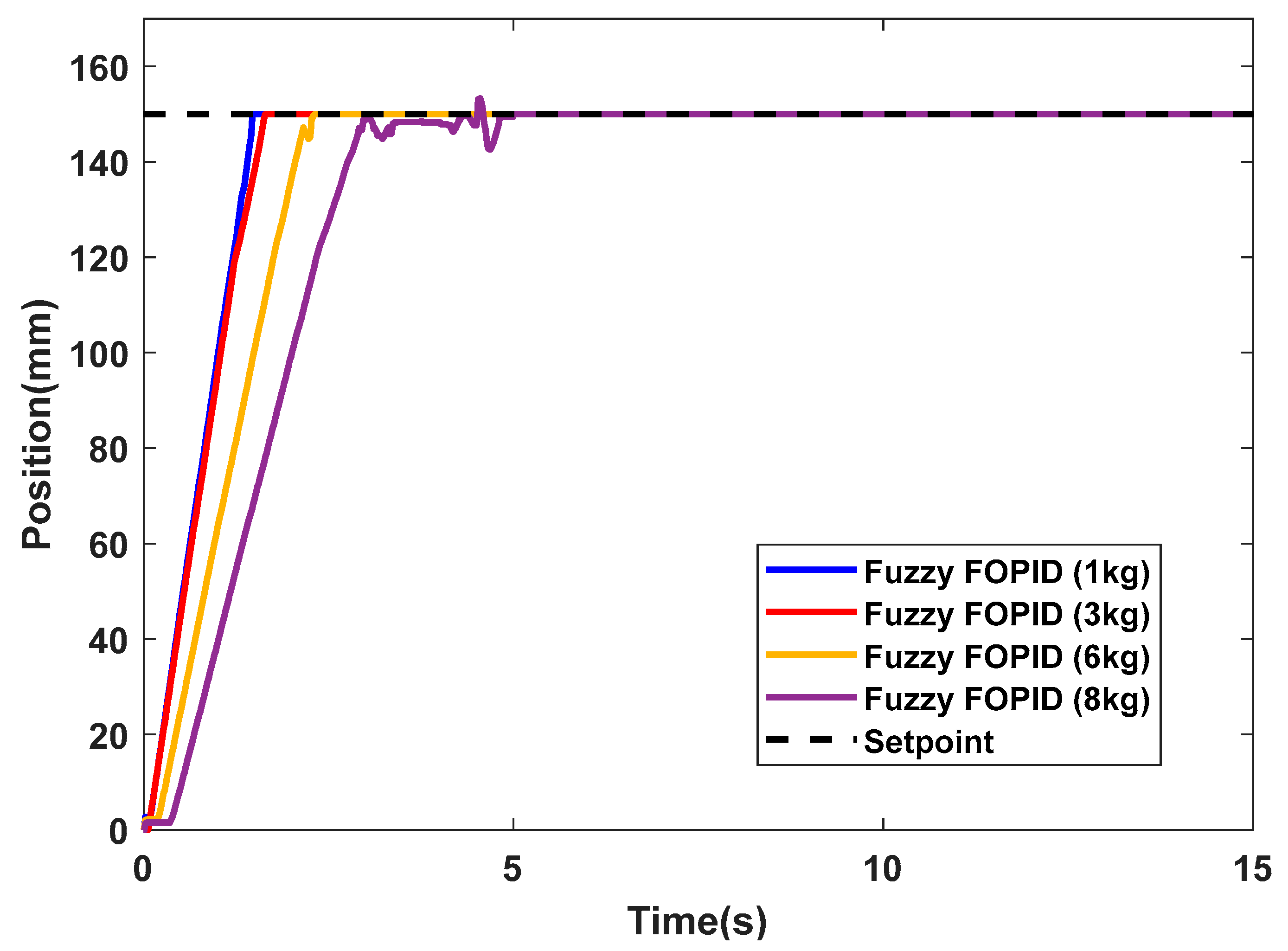
| Loads (kg) | Fixed Position at 100 mm | Fixed Position at 150 mm | ||
|---|---|---|---|---|
| Rise Time Tr (s) | Settling Time Ts (s) | Rise Time Tr (s) | Settling Time Ts (s) | |
| 1 | 0.7199 | 0.9763 | 1.1513 | 1.4590 |
| 3 | 0.8290 | 1.0781 | 1.2435 | 1.6047 |
| 6 | 1.1002 | 1.4944 | 1.6076 | 2.2613 |
| 8 | 1.6912 | 3.0097 | 2.0625 | 4.7827 |
| Criteria | K1 | K2 | Kp | Kpi | Kpd | Ki | λ | Kd | µ |
| Fuzzy FOPID | 0.0495 | 0.0001 | 0.1 | - | - | 0.15 | 1 | 1 | 0.1 |
| FOPI-FOPD | - | - | - | 1 | 1 | 0.01 | 0.1 | 1 | 1 |
| Controllers | Performance Index | |||
|---|---|---|---|---|
| Rise Time Tr (s) | Settling Time Ts (s) | Overshoot OS (%) | Steady-State Error ess (%) | |
| FOPI-FOPD | 2.091 | 3.910 | 0.0055 | 0 |
| Cascade Fuzzy FOPID | 0.6682 | 1.1359 | 0.2768 | 0 |
| Controllers | Performance Index | |||
|---|---|---|---|---|
| Rise Time Tr (s) | Settling Time Ts (s) | Overshoot OS (%) | Steady-State Error ess (%) | |
| FOPI-FOPD Fuzzy FOPID | 0.3710 | 10.7986 | 35.5380 | 1.3520 |
| Cascade Fuzzy FOPID | 0.8235 | 4.9381 | 9.8500 | 0 |
Disclaimer/Publisher’s Note: The statements, opinions and data contained in all publications are solely those of the individual author(s) and contributor(s) and not of MDPI and/or the editor(s). MDPI and/or the editor(s) disclaim responsibility for any injury to people or property resulting from any ideas, methods, instructions or products referred to in the content. |
© 2023 by the authors. Licensee MDPI, Basel, Switzerland. This article is an open access article distributed under the terms and conditions of the Creative Commons Attribution (CC BY) license (https://creativecommons.org/licenses/by/4.0/).
Share and Cite
Muftah, M.N.; Faudzi, A.A.M.; Sahlan, S.; Mohamaddan, S. Fuzzy Fractional Order PID Tuned via PSO for a Pneumatic Actuator with Ball Beam (PABB) System. Fractal Fract. 2023, 7, 416. https://doi.org/10.3390/fractalfract7060416
Muftah MN, Faudzi AAM, Sahlan S, Mohamaddan S. Fuzzy Fractional Order PID Tuned via PSO for a Pneumatic Actuator with Ball Beam (PABB) System. Fractal and Fractional. 2023; 7(6):416. https://doi.org/10.3390/fractalfract7060416
Chicago/Turabian StyleMuftah, Mohamed Naji, Ahmad Athif Mohd Faudzi, Shafishuhaza Sahlan, and Shahrol Mohamaddan. 2023. "Fuzzy Fractional Order PID Tuned via PSO for a Pneumatic Actuator with Ball Beam (PABB) System" Fractal and Fractional 7, no. 6: 416. https://doi.org/10.3390/fractalfract7060416