Article

Robust Trajectory Tracking Control for Serial Robotic Manipulators Using Fractional Order-Based PTID Controller

by
Banu Ataşlar-Ayyıldız
Department of Electronics and Communications Engineering, Kocaeli University, Kocaeli 41001, Turkey
Fractal Fract. 2023, 7(3), 250; https://doi.org/10.3390/fractalfract7030250
Submission received: 4 January 2023 / Revised: 2 March 2023 / Accepted: 7 March 2023 / Published: 9 March 2023
(This article belongs to the Special Issue Applications of Fractional-Order Calculus in Robotics)

Abstract

:
The design of advanced robust control is crucial for serial robotic manipulators under various uncertainties and disturbances in case of the forceful performance needs of industrial robotic applications. Therefore, this work has proposed the design and implementation of a fractional order proportional tilt integral derivative (FOPTID) controller in joint space for a 3-DOF serial robotic manipulator. The proposed controller has been designed based on the fractional calculus concept to fulfill trajectory tracking with high accuracy and also reduce effects from disturbances and uncertainties. The parameters of the controller have been optimized with a GWO–PSO algorithm, which is a hybrid tuning method, by considering the time integral performance criterion. The superior and contribution of the GWO–PSO-based FOPTID controller has been demonstrated by comparing the results with those offered by PID, FOPID and PTID control strategies tuned by the GWO–PSO. The examination of the results showed that the proposed controller, which is based on the GWO–PSO algorithm, demonstrates better trajectory tracking performance and increased robustness against various trajectories, external disturbances, and joint frictions as compared to other controllers under the same operating conditions. In terms of the trajectory tracking performance for robustness, the superiority of the proposed controllers tuned by GWO–PSO has been confirmed by 20.2% to 44.5% reductions in the joint tracking errors. Moreover, for assessing the energy consumption of the tuned controllers, the total energy consumption of the proposed controller for all joints has been remarkably reduced by 2.45% as compared to others. Consequently, the results illustrated that the proposed controller is robust and stable and sustains against the continuous disturbance.

1. Introduction

Robotic manipulators are dynamically coupled and highly non-linear systems. Furthermore, in the case of various uncertainties and external or internal disturbances during their operations, effective control is needed to provide highly precise trajectory tracking and execute accurate positioning in various fields such as process industries, space applications and medical areas [1]. Due to the highly non-linear and uncertain dynamics of the robotic manipulators, accurate and robust trajectory tracking becomes even more challenging. For this reason, traditional proportional-integral-derivative (PID) controllers are generally not suitable for providing the high-performance trajectory tracking control in such operations that require high precision. In order to design a robust control strategy which is able to improve stability and performance tracking, fractional order (FO) controller design is considered using the incorporation of fractional calculus and traditional PID control approaches.
In the design of the FO controller, the orders of integral and derivative operators are indicated by non-integer values as compared to integers. Thus, in controller design, extra flexibility is provided by adding integral and derivative fractional powers to the full-order controller. The first use of FO operators in control was suggested by Oustaloup [2], who proposed a robust FO control approach called CRONE (Commande Robuste d’Ordre Non-Entier) [3,4]. The most well-known FO controller among control engineers is the fractional order PID (FOPID) controller presented by Podlubny [5]. For the controller design of the robotic manipulators in trajectory tracking control, methods based on the fractional order calculus have been widely used and cited by several authors. Bingul and Karahan [6] designed a FOPID controller optimized with Particle Swarm Optimization (PSO) and Genetic Algorithm (GA) for the trajectory tracking problem of a 2-DOF planar robotic manipulator. By employing the Matlab FMINCON function, which searches the optimal parameters of the controller, Angel and Viola [7] evaluated the FOPID controller with computer torque control strategy under external disturbances for the trajectory tracking control of a robotic manipulator type delta. The FOPID controller tuned by the Bat optimization algorithm was proposed by Al-Mayyahi et al. [8] for circular path tracking of a 3-RRR planar parallel robot platform without and with disturbance. Zhang et al. [9] studied fast spatial positioning and trajectory tracking of a 5-DOF drilling anchor manipulator by using FOPID control based on the four intelligent optimization algorithms such as Whale Algorithm (WOA), GA, PSO, and Search Algorithm (GPS) in that paper. Sharma et al. [10] presented two degree of freedom fractional order PID (2-DOF FOPID) controller tuned by Cuckoo Search (CS) algorithm for trajectory tracking task of a 2-DOF robotic manipulator with payload under model uncertainties, external disturbances, random noise and payload variations with time. Considering a 3-DOF parallel manipulator known as the Maryland manipulator, Dumlu and Erenturk [11] designed the FOPID control approach using a pattern search algorithm for improving the tracking performance of the manipulator in the case of high speed, high accuracy and high acceleration needed.
Different control strategies based on FO controllers have been designed and used in different applications in order to make an efficient control. One of them is the tilt-integral-derivative (TID) controller, which has been firstly presented by Lurie [12]. In the TID controller, which is closely related to the FOPID controller, the proportional parameter of the PID is replaced with a tilted one having a transfer function s 1 / n . By means of the resulting transfer function of the entire controller, the TID controller can achieve better disturbance rejection and reduce the effects of the system parameter changes for the closed-loop system as compared to the PID controller. Various applications of TID controller have been made in the literature, depending on a suitable choice of optimization algorithms for fine-tuning the controller parameters, for validating its superiority over PID controller in terms of improving the stability of the system and enhancing the speed of the controller response [13,14,15,16,17,18,19]. On the other hand, in order to improve the control performance and enhance the transient response of the TID controller, a concept of a fractional order-based TID controller has been recently indicated in the literature review. Sharma et al. [20] proposed a fractional order-based TID controller tuned by Salp Swarm Algorithm (SSA) for frequency regulation in a hybrid power system. Moreover, the results from the designed controllers based on SSA and Gray Wolf Optimization (GWO) algorithms were compared with existing controllers in terms of transient response characteristics and error indices. As a result, in that paper, the simulations prove the advisability of the fractional order TID controller in the presence of system parameter uncertainties, random load changes and different types of the system. In another study by the same authors [21], a dual-stage controller composed of fractional order-based TID and integer order proportional derivative (PD) controllers was presented for exhibiting fast and robust disturbance rejection performance of the proposed control scheme in load frequency control applications. On the other hand, a systematic tuning approach of the fractional-based robust TID controller was proposed by Lu et al. [22] for first-order plus time delay and high-order processes. In that paper, the design process of the robust TID controller and the corresponding steps were given in detail. Finally, the simulation results clearly indicated that the proposed controller achieved superior robustness and improved transient performance compared to the PID, FOPI and FOPID controllers.
For the purpose of enhancing the TID controller with more degree of freedom as compared to its integer derivative and integral terms, the fractional order integral and derivative terms are added. Thus, a hybrid controller is obtained for utilizing the features of FOPID and TID controllers. Mohamed et al. [23] designed a hybrid controller composed of TID and FOPID controllers for the load frequency control. Furthermore, the six different tunable parameters in the designed controller were optimized with a Manta Ray Foraging (MRF) algorithm by using the integral squared error criterion. In that paper, the robustness of the designed controller was examined under the variation of the system parameters and the load disturbances. By using the same control strategy, Ahmet et al. [24] proposed a modified hybrid fractional order controller, including FOPID and TID controllers for load frequency and the control of electric vehicles. Moreover, for determining the optimal parameters of the hybrid controller, the Artificial Ecosystem Optimization (AEO) algorithm was employed in that paper. It was noteworthy from the simulation results that the proposed hybrid controller demonstrates substantially superior, robust and stable performance over a wide range of fast responses during transients and parameters uncertainty. Based on this hybrid control scheme, Choudhary et al. [25] suggested a hybrid controller comprising a fractional order PI (FOPI) controller and fractional order proportional tilted integral derivative (FOPTID) controller for stabilizing the frequency and tie-line power variations in a power system. The parameters of the FOPI-FOPTID controller were adjusted by employing Global Neighborhood Algorithm (GNA) and Ant Colony Optimization (ACO) algorithms. The results revealed that the proposed FOPI-FOPTID controller provides better dynamic response and error criteria than PID, FOPID and FOPI-FOPID controllers optimized with the same optimization algorithms. Another hybrid controller based on FOPTID was proposed by Yanmaz et al. [26] for the effective control of a static compensation system. In that study, a FOPID-based model predictive controller (FOPID-MPC), TID-based MPC controller and the proposed FOPTID-based MPC (FOPTID-MPC) controller were optimized with Pathfinder Optimization Algorithm (POA) and also their transient responses and error indices were compared for showing their control performance. Consequently, the simulation results have demonstrated the effectiveness of the proposed FOPTID-MPC controller.
It is clear from the available literature that various control designs based on the TID controller using different optimization algorithms have been addressed for various applications. Furthermore, the compatibility of FOPID and TID controllers and the effect of the combination of them have not been evaluated and tackled in the literature for trajectory tracking control of the robotic manipulator. In this context, an efficient FOPTID controller tuned via GWO–PSO is demonstrated in realizing the trajectory tracking of a serial robotic manipulator in this work. The main contributions of this research article can be summarized as follows:
  • To the best knowledge of the author, a FOPTID controller based on the combination of TID and FOPID controllers is firstly designed with a GWO–PSO algorithm to provide the trajectory tracking of a 3-DOF serial robotic manipulator under friction, external disturbance and different trajectories. This hybrid controller has major advantages in improving trajectory tracking control performance and enhancing robustness.
  • In order to demonstrate the effectiveness of the proposed controller, PID, FOPID and PTID controllers are designed with the same optimization algorithm for carrying out trajectory-tracking tasks under the same conditions.
  • By eliminating the effects of internal and external disturbances as total disturbance, the proposed FOPTID controller is more capable of dealing with the total disturbance during the reference trajectory tracking than existing controllers. Accordingly, better tracking accuracy is provided by the FOPTID controller.
The organization of the paper is as follows: In Section 2, the mathematical model of the first three links of the Staubli RX-60 manipulator is presented. The structures of the fractional order controllers are described in Section 3. The hybrid optimization algorithm GWO–PSO is given in Section 4. Furthermore, the objective function chosen for optimization studies and the proposed overall control system are also described in the same section. Simulation results are presented and discussed in Section 5, and finally, concluding remarks are presented in Section 6.

2. Dynamic Model of the Manipulator

In this study, a robust control for trajectory tracking is designed by considering the first three links of the Staubli RX-60 manipulator having the frame configuration presented in Figure 1. A brief overview of the mathematical model of the system is presented in this section.
The dynamics of the rigid body for robotic manipulators can be given as the following formulation:
τ = D θ θ ¨ + C θ , θ ˙ + G ( θ ) + τ f
where θ , θ ˙ , and θ ¨ are joint angles, velocities and accelerations, respectively. D θ , C θ , θ ˙ , and G ( θ ) are the inertia matrix, the coriolis/centripetal matrix and the gravity vector, respectively. τ f is the robotic uncertainties and disturbances comprising viscous and static friction torque, and finally, τ is the control input torque.
The dynamics of the first three links of the robot can be modelled as:
τ 1 τ 2 τ 3 = d 11 d 12 d 13 d 21 d 22 d 23 d 31 d 23 d 33 θ ¨ 1 θ ¨ 2 θ ¨ 3 + c 1 ( θ , θ ˙ ) c 2 ( θ , θ ˙ ) c 3 ( θ , θ ˙ ) + g 1 ( θ ) g 2 ( θ ) g 3 ( θ ) + τ f 1 τ f 2 τ f 3
The Denavit-Hartenberg (D-H) parameters of the robot and the other details about the elements of matrices D θ , C θ , θ ˙ , and G ( θ ) are available in [27]. The friction torque for each joint i is defined as:
τ f i = F c i s i g n θ ˙ i + F v i θ ˙ i
where F c i and F v i are the Coulomb friction and viscous friction constants, respectively. By substituting the system parameters into Equation (2), the control input torque equation for each joint is obtained as follows [27]:
τ 1 = [ c 2 θ 2 ( a 2 2 m 3 + m 2 a 2 c 2 + B y y 2 ) + A x x 2 s 2 θ 2 + B y y 3 c 2 ( θ 2 + θ 3 ) c θ 2 2 m 3 a 2 s θ 2 + θ 3 d 4 c + 2 F 2 s θ 2 2 F 3 c θ 2 + θ 3 s θ 2 + θ 3 + s 2 θ 2 + θ 3 m 3 d 4 c 2 + A x x 3 + m 3 d 3 2 + C z z 1 θ ¨ 1 + c θ 2 D 2 + s θ 2 E 2 + a 2 d 3 m 3 + c θ 2 + θ 3 D 3 d 3 m 3 d 4 c + E 3 s θ 2 + θ 3 θ ¨ 2 + c θ 2 + θ 3 D 3 d 3 m 3 d 4 c + E 3 s θ 2 + θ 3 θ ¨ 3 + s 2 θ 2 a 2 2 m 3 + m 2 a 2 c 2 + B y y 2 + s 2 θ 2 A x x 2 s 2 θ 2 + θ 3 B y y 3 + 2 m 3 a 2 d 4 c c θ 2 + θ 2 + θ 3 2 F 2 c 2 θ 2 2 F 3 c 2 θ 2 + θ 3 + s 2 θ 2 + θ 3 m 3 d 4 c 2 + A x x 3 θ ˙ 2 θ ˙ 1 + s θ 2 D 2 + c θ 2 E 2 + a 2 d 3 m 3 s θ 2 + θ 3 D 3 d 3 m 3 d 4 c + E 3 c θ 2 + θ 3 θ ˙ 2 2 + 2 s θ 2 + θ 3 D 3 d 3 m 3 d 4 c + E 3 c θ 2 + θ 3 θ ˙ 2 θ ˙ 3 + s 2 θ 2 + θ 3 B y y 3 c θ 2 c θ 2 + θ 3 2 m 3 a 2 d 4 c 2 F 3 c 2 θ 2 + θ 3 + s 2 θ 2 + θ 3 m 3 d 4 c 2 + A x x 3 θ ˙ 3 θ ˙ 1 + s θ 2 + θ 3 D 3 d 3 m 3 d 4 c + E 3 c θ 2 + θ 3 θ ˙ 3 2 + F c 1 s i g n θ ˙ 1 + F v 1 θ ˙ 1
τ 2 = [ c θ 2 D 2 + s θ 2 ( E 2 + a 2 d 3 m 3 ) + c θ 2 + θ 3 D 3 d 3 m 3 d 4 c + E 3 s θ 2 + θ 3 θ ¨ 1 + C z z 2 + C z z 3 + m 2 a 2 c 2 + m 3 a 2 2 + d 4 c 2 + 2 s θ 3 a 2 d 4 c m 3 θ ¨ 2 + m 3 d 4 c 2 a 2 m 3 s θ 3 d 4 c + C z z 3 θ ¨ 3 1 2 s 2 θ 2 A x x 2 a 2 2 m 3 + m 2 a 2 c 2 + B y y 2 + s 2 θ 2 + θ 3 m 3 d 4 c 2 + A x x 3 B y y 3 + 2 m 3 a 2 d 4 c c θ 2 + θ 2 + θ 3 2 F 2 c 2 θ 2 2 F 3 c 2 θ 2 + θ 3 θ ˙ 1 2 + 2 c θ 3 a 2 m 3 d 4 c θ ˙ 3 θ ˙ 2 + c θ 3 a 2 m 3 d 4 c θ ˙ 3 2 + g 0 m 3 d 4 c s θ 2 + θ 3 + g 0 m 2 a 2 c c θ 2 + g 0 a 2 m 3 c θ 2 + F c 2 s i g n θ ˙ 2 + F v 2 θ ˙ 2
τ 3 = [ c θ 2 + θ 3 ( D 3 d 3 m 3 d 4 c ) + E 3 s θ 2 + θ 3 θ ¨ 1 + m 3 d 4 c 2 s θ 3 a 2 m 3 d 4 c + C z z 3 θ ¨ 2 + m 3 d 4 c 2 + C z z 3 θ ¨ 3 1 2 s 2 θ 2 + θ 3 B y y 3 c θ 2 c θ 2 + θ 3 2 m 3 a 2 d 4 c 2 F 3 c 2 θ 2 + θ 3 + s 2 θ 2 + θ 3 m 3 d 4 c 2 + A x x 3 ] θ ˙ 1 2 1 2 2 c θ 3 a 2 m 3 d 4 c θ ˙ 2 2 + g 0 m 3 d 4 c s θ 2 + θ 3 + F c 3 s i g n θ ˙ 3 + F v 3 θ ˙ 3

3. Design of Controllers

In this work, the design of a fractional order proportional tilt integral derivative (FOPTID) controller for the presented 3-DOF serial robotic manipulator has been proposed and investigated. Furthermore, several controllers are applied to the same system under the same conditions in order to examine the performance of the proposed controller. The purposed FOPID, PTID and FOPTID controllers contain non-integer order integral and derivative. Therefore, fractional calculus is needed for implementation of them.

3.1. Fractional Calculus

Fractional calculus includes operations where the degree of derivative and integral is not an integer but with real or even complex values [28]. The fractional order operator D t α a is defined as follows:
D t α a = d α / d t α , R z > 0 1 , R z = 0 a t d τ α R z < 0
where a and t are the limits of the operation, and α is the non-integer degree of the derivative and integral. Several approaches have been developed for designing the fractional order derivative and integral operators. One of the approaches is Riemann–Liouville (R–L) [17]. The definition of Riemann and Loiuville is as follows:
D t α a f ( t ) = 1 Γ ( n α ) d n d t n a t f ( τ ) ( t τ ) α n + 1 d τ
where Γ · is the Euler’s Gamma Function:
Γ z = 0 e t t z 1 d t ,   for   R z > 0
In general, the Laplace transform is used to describe derivative and integral for simplicity. The Laplace transform can be defined as:
L D t α a f ( t ) = s α F s k = 0 n 1 s k D t α k 1 a f ( t ) t = 0
where L f ( t ) is the Laplace Transform of the function f ( t ) . Under zero initial conditions, with the non-integer value of α , the Laplace transform of D t α a f ( t ) is:
L D t α a f ( t ) = s α F s
The Oustaloup Recursive Approximation Method is one of the several approximation methods proposed in the literature for the implementation of the fractional order function s α . The Oustaloup Recursive Approximation Method uses an Nth order analog filter to approximate the fractional order function in a certain frequency range ω b , ω h . ω b and ω h are the lower and upper-frequency bounds, respectively. The approximate transfer function for s α is expressed by integer order equivalent transfer function:
s α = K k = N N s + ω z k s + ω p k
where K is gain, ω z k are zeros and ω p k are poles of the filter [29]. This approximate transfer function has 2 N + 1 poles and zeros. The poles, zeros and gain are calculated below, respectively [29]:
ω p k = ω b ω h ω b k + N + 1 2 + a 2 2 N + 1
ω z k = ω b ω h ω b k + N + 1 2 a 2 2 N + 1
K = ω h ω b α 2 k = N N ω p k ω z k
As mentioned above, in this study, the FOPTID, FOPID, and PTID controllers are applied to the robotic manipulator. These fractional order controllers are implemented by using Oustaloup Recursive Approximation [30]. In this study, the value of N is chosen as 5, and the frequency range is chosen as: ω b , ω h = 10 2 , 10 + 2 rad/s.

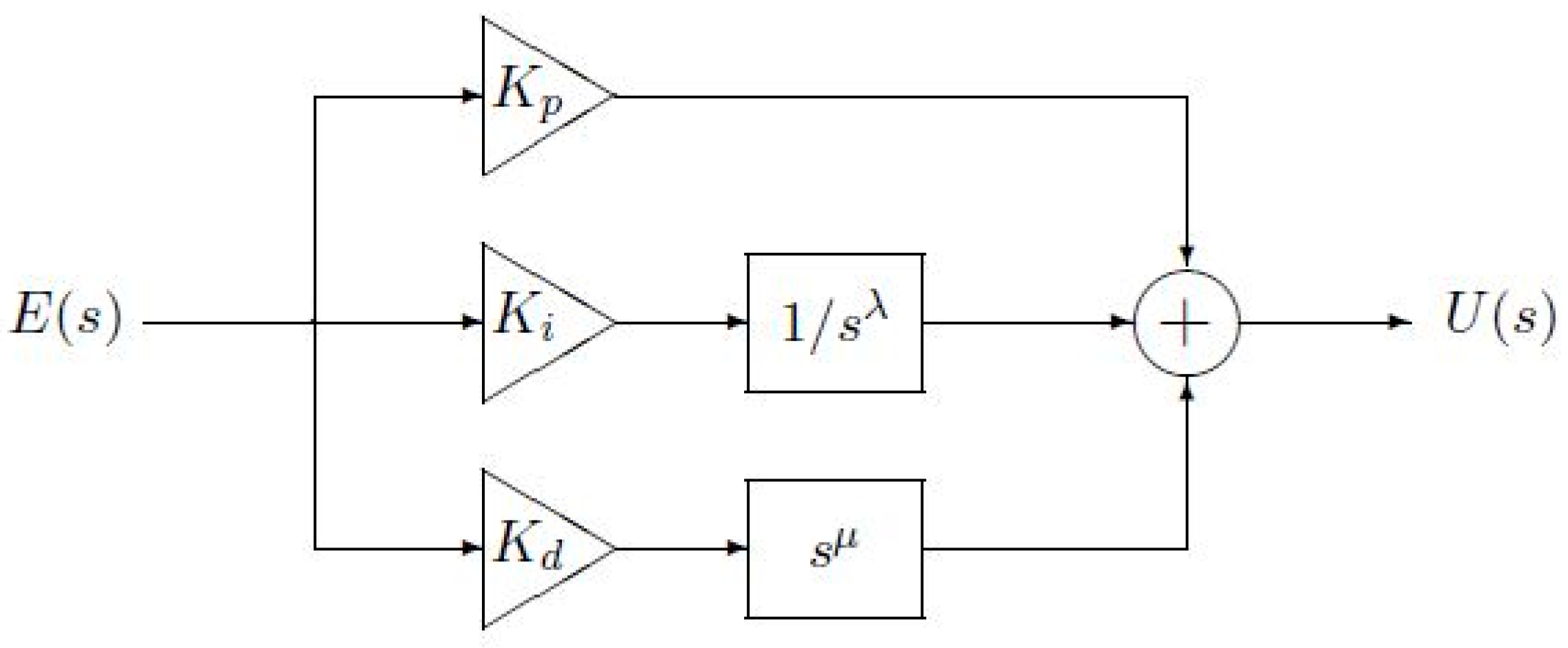
3.2. Fractional Order Controllers

Due to the simple design and construction of integer order PID controllers, they are still widely used in many industrial applications. The PID controller comprises three coefficients: proportional coefficient ( K p ), integral coefficient ( K i ) and derivative coefficient ( K d ) to produce the control action. The transfer function of PID can be stated as:
C P I D s = K p + K i 1 s + K d s
On the other hand, due to the highly non-linear and uncertain dynamics of the robotic manipulator, the trajectory tracking control problem is quite difficult. Therefore, in general, conventional integer order PID controllers are not suitable for providing high-performance trajectory tracking control in precision operations. In order to design a robust control strategy which can improve stability and tracking performance, fractional order-based controller is considered by applying fractional calculus to the conventional PID control approaches.
A FOPID controller is depicted by five parameters. In comparison to the conventional PID controllers, FOPID controllers have two more parameters in which the orders of the integral part λ and derivative part μ are non-integer. These additional parameters bring more flexibility to the design of the controller and also may lead to obtaining an enhanced dynamic performance. The structure of the FOPID is shown in Figure 2 which E ( s ) and U ( s ) represent the error and the control signals, respectively.
The transfer function of the FOPID controller is given below:
C F O P I D s = K p + K i 1 s λ + K d s μ
One of the different control strategies based on Fractional Order Calculus is the PTID control method. The design of the PTID controller has been proposed quite recently in [25], and, in fact, it is a modified version of the TID controller. On the other hand, the only difference between the TID controller from conventional PID is that its proportional parameter is replaced with a tilted one having a transfer function s 1 / n [12]. Thanks to these modifications, the PTID controller can achieve better disturbance rejection and reduce the effects of the system parameter changes for the closed-loop system as compared to the PID controller.
The structure of the PTID controller is presented in Figure 3. As shown in the figure, the proportional term, K p , is added to the TID controller. Therefore, the transfer function of the PTID controller is:
C P T I D s = K p + K t 1 s 1 / n + K i 1 s + K d s
As examined in the works [25,26,31,32] in the literature, FO controllers are more stable and useful in various control applications. Also, the TID controllers are able to reject disturbances, respond quickly and be consistent with uncertainties in linear and nonlinear control implementations. Moreover, they have several tuning parameters. Thus, superior performance for both of them can be obtained in control implementations. Considering their great qualities, a FOPTID controller is proposed as a hybrid controller of FOPID and PTID in [25]. The structure of the FOPTID controller is shown in Figure 4. FOPTID controller has the non-integer order of integral and derivative coefficients of the PTID controller. By defining λ and μ as the integral and derivative non-integer orders, respectively, the transfer function of the FOPTID controller is:
C F O P T I D s = K p + K t 1 s 1 / n + K i 1 s λ + K d s μ
In this study, the effect of the FOPTID controller on the trajectory-tracking control of the robotic manipulator will be evaluated. In this regard, an efficient FOPTID controller can be obtained by tuning with the hybrid optimization algorithm GWO–PSO, which will be presented in the next section.

4. Optimization Tasks

The parameters of the proposed controller have been optimized with a hybrid GWO–PSO algorithm by considering a specific objective criterion. The superior and contribution of the GWO–PSO-based FOPTID controller has been demonstrated by comparing the results with those offered by PID, FOPID and PTID control strategies tuned by the same algorithm.

4.1. Optimization Algorithm

4.1.1. Particle Swarm Optimization (PSO) Algorithm

Particle swarm optimization is a population-based stochastic optimization method that was first proposed in 1995 to obtain the best results on nonlinear numerical problems by modeling the movements of living swarms [33]. The PSO algorithm finds out an optimal solution among the randomly distributed particles in a swarm. Essentially, each particle within the swarm indicates a potential solution with its particular velocity and position. In this context, for each iteration of the PSO algorithm, the velocity and position of the particles are updated according to the following expressions, respectively:
v i k + 1 = ξ v i k + φ 1 r a n d 1 p b e s t i p i k + φ 2 r a n d 2 ( g b e s t p i k )
p i k + 1 = p i k + v i k + 1
In these equations, v i k is the velocity of the ith particle for the k iteration, p i k is the position of the ith particle for the k iteration, ξ represents the inertial weight function, φ 1,2 represents the learning factors, and r a n d 1,2 represents the random number values assigned in the range of [0, 1]. In addition, p b e s t i is the coordinates that provide the best solution that particle i has achieved so far. g b e s t is also the coordinates that provide the best solution obtained over all particles. Figure 5 shows the two-dimensional motion of one of the particles depending on the terms defined above.

4.1.2. Gray Wolf Optimization (GWO) Algorithm

As a swarm-based optimization method, inspiration for Gray Wolf Optimization comes from the behavior and the hunting strategy of the grey wolves in nature. Based on the social hierarchy as depicted in Figure 6, gray wolves are classified into four groups as alpha (α), beta (β), delta (δ) and omega (ω). As seen from the figure, the social hierarchy goes down from top to bottom, and the leading group consists of alpha wolves. Beta wolves help alpha wolves in making decisions. As the third level, the delta wolves’ mission is to submit to alpha and beta wolves but control the omega wolves. The least priority wolves are the omegas, which must follow the leading grey wolves [34].
In the GWO algorithm, the encircling behaviour of the grey wolves is modeled with the below equations:
D = C × X p k X ( k )
X ( k + 1 ) = X p k A × D
In these equations, k is the number of iterations and the X and X p are the position vectors of the grey wolves and the prey, respectively. A and C are the coefficient vectors and calculated as given below:
A = a × ( 2 × r 1 1 )
C = 2 × r 2
where a is linearly decreased from 2 to 0 through iteration steps and r 1 and r 2 are random vectors within [0, 1].
In the GWO algorithm, hunting and encircling prey are modelled by the following equations:
D α = C 1 × X α X ( k ) D β = C 2 × X β X ( k ) D δ = C 1 × X δ X ( k )
X 1 = X α A 1 D α X 2 = X β A 2 D β X 3 = X δ A 3 D δ
X ( k + 1 ) = X 1 + X 2 + X 3 3
where D α , D β , and D δ vectors represent the distances between the ω wolves and α, β and δ wolves, respectively. X 1 , X 2 , and X 3 vectors represent the relative positions based on α, β and δ wolves, respectively. The updating process of positions for each group of wolves is also depicted in Figure 7.

4.1.3. GWO–PSO Algorithm

In this work, GWO is hybridized with a PSO method to improve the progress of the GWO. The hybrid GWO–PSO has been seen as an effective optimization technique when searching for the best solution globally to an optimization problem [35]. The pseudo-code of the GWO–PSO algorithm is presented in Figure 8.
The best positions of the grey wolves obtained at the end of the GWO–PSO algorithm represent the parameters of the controllers for each joint of the robot as follows:
PID :   K p , K i , K d
FOPID :   K p , K i , K d , λ , μ
PTID :   K p , K i , K d , K t , n
FOPTID :   K p , K i , K d , K t , λ , μ , n

4.2. Objective Function

In this study, the objective function used in optimization of the controller parameters is chosen as ITAE (Integral of Time Absolute Error) for each joint of the 3-DOF robotic manipulator. Thus, the objective function is given as the following:
J I T A E = i = 1 3 0 t t e i t d t
Here, t is the time and e i t is the trajectory error for joint i .

4.3. Proposed Control System Framework

The schematic diagram of the proposed control system is presented in Figure 9. The optimal parameters of PID, FOPID, PTID and FOPTID controllers are found by using the GWO–PSO algorithm. The number of maximum iteration is set to 100 in the algorithm. Moreover, the optimal controller parameters are obtained after 10 runs of the algorithm.
Based on the detailed literature review, during the optimization, the lower and upper boundaries of the parameters are set to K p , K i , K d , K t 0,350 , μ , λ 0,2 and n 0,300 .
In addition, the simulation time is adjusted differently in each simulation process according to the type of reference trajectory signal, with a fixed interval time of 0.001 s.

5. Simulation Results and Discussions

In this section, the robustness and effectiveness of the proposed control strategy have been comparatively verified on the first three-link of a 6-DOF serial robotic manipulator. The order of tasks for simulations is as follows: Firstly, tuning the parameters of the presented controllers by GWO–PSO and demonstrating the results from trajectory tracking; Secondly, testing the proposed control scheme by comparing with the PID, FOPID and PTID controllers and showing the results obtained from the different trajectory, internal and external disturbances. Design of the overall system model and the optimization with the GWO–PSO are simulated using MATLAB/SIMULINK environment, and also all simulations have been executed on a personal computer having an Intel CoreTM i5-7200U CPU @ 2.50 GHz processor and 8.0 GB RAM. Furthermore, a Ninteger toolbox [36] is used in the MATLAB environment as the approximator for simulating the fractional order terms of FOPID, PTID and FOPTID controllers.

5.1. Trajectory Tracking Analysis

In order to achieve the trajectory tracking in joint space, firstly, four control strategies (PID, FOPID, PTID and FOPTID) are optimized by GWO–PSO for each joint using the trajectory tracking evaluation ( J I T A E ) with respect to the given path for the end-effector of the robot. During this tunning tasks, it is assumed that there is no friction. That means the values of F c i and F v i are taken as zero in Equation (3) of the mathematical model. The presence of friction will be taken into account in one of the robustness tests. After optimization, for comparing the tracking performance of the tuned controllers, the mean of absolute error (MAE) for each joint over the trajectory is computed as follows:
M A E i = 1 N j = 1 N e i j
where e i ( j ) is the trajectory error of jth sample of ith joint and N is the number of samples. At the end of conducting a total of 10 individual trials depending on the generated random numbers, eventually, the obtained optimal controller parameters and MAE values for the presented control strategies are given in Table 1. For analysis of the total tracking performance of the proposed approach, the comparison of the J I T A E values based on four potential control approaches, namely PID, FOPID, PTID and FOPTID controllers, are illustrated in Figure 10. In addition, the reference path of the end-effector, the corresponding reference and system output trajectories in each joint are depicted in Figure 11 for a better view of tracking the reference trajectories of each joint based on the tuned controllers.
From Figure 10, it is revealed that the proposed FOPTID approach tuned by GWO–PSO has the smallest J I T A E value. The improvement in J I T A E is resulting from the introduction of fractional operators in the FOPTID controller, which adds extra design variables. Therefore, the proposed control approach is able to maintain relatively higher trajectory tracking accuracy when compared to the PID, FOPID and PTID approaches.
As shown in Figure 11, all of the actual joint positions can track the desired joint trajectories by using the tuned controllers. It is inferred that a remarkable tracking performance for all joints is achieved by the PTID and FOPTID controllers. Furthermore, from Figure 10 and Figure 11 and Table 1, it can be seen that the proposed FOPTID method has better control performance in comparison with the existing controllers under a more complex joint trajectory tracking task.

5.2. Robustness Testing: Different Trajectory

In actual situations, the effectiveness of the tuned controllers is investigated under different joint trajectories or paths traced by the end-effector of the robot in task space. The desired path and actual path in task space and the corresponding joint trajectories are shown in Figure 12 for observing the improvements in tracking errors based on the tuned controllers. Moreover, in order to demonstrate a quantitative comparison among the results, the MAE values of the joint errors ( e j ) and the root mean square (RMS) values of the control signals ( τ j ) for each joint are calculated as shown in Figure 13.
As shown in Figure 12, the end-effector trajectory tracking based on the FOPTID controller exhibits almost the same results as the end-effector tracking based on the PTID controller. On the other hand, when using the proposed FOPTID controller tuned by GWO–PSO, the trajectory tracking precision is relatively higher as compared to the other tuned controllers. From joint space, it can be observed that all trajectory tracking controllers can make the robot track the joint reference trajectory. However, the TID-based trajectory tracking control approaches can accurately track the change in the joint angle and maintain stability.
As can be observed from Figure 13, the designed controllers yield almost the same RMS control action values for joint 1, while the TID-based controllers produce smaller MAE error values as compared to others. In addition, compared to the controllers (PID and PTID or FOPID and FOPTID), the TID-based controllers need lesser applied torque for tracking the desired joint trajectories than the PID-based controllers.

5.3. Robustness Testing: Disturbance Rejection

To verify the disturbance rejection ability of the TID-based controllers, a sinusoidal torque signal is added to the control signal. This external disturbance, applied to each joint, is given as follows:
τ d ( t ) = 0   N m , t < 2 250 sin t + 250   [ N m ] 350 sin t + 350   N m , 450 sin t + 450   [ N m ] t 2   f o r   j o i n t   1 ,   2   a n d   3 , top-down .
The desired path and actual path in joint space are shown in Figure 14 for each joint. Furthermore, the associated MAE values are illustrated in the same figure.
As can be seen from Figure 14, under sinusoid disturbance, better trajectory tracking is achieved with the TID-based controllers (PTID and FOPTID) as compared to the PID and FOPID controllers, which are quite obvious in trajectories and the amplitude of the heading angles. On the other hand, the difference between the trajectory tracking accomplished by means of the PTID and FOPTID controllers is almost small in each joint. Regarding MAE values demonstrated in Figure 14, the TID-based controllers produce a smaller tracking error in each joint than the other controllers. These simulation results reveal that although the applied perturbation directly affects the trajectory tracking error, the proposed robust FOPTID controller can exhibit better performance with a higher trajectory tracking accuracy against sinusoid disturbance than the other controllers and also maintain the error trajectories of each joint inside a compact set.

5.4. Robustness Testing: Friction Compensation

In order to demonstrate the robustness of the TID-based controllers and also compare them with other designed controllers in the presence of joint friction, the friction model, including Coulomb plus viscous friction, is adopted for each joint in the practical friction compensation of the 3-DOF robot manipulator. The friction parameters related to the Coulomb plus viscous friction model are given in Table 2 for each joint. The time profiles of joint positions and corresponding tracking errors based on PID, FOPID, PTID and FOPTID controllers are illustrated in Figure 15 for each joint under friction.
In accordance with Figure 15, the convergence of the tracking error when using the PTID control scheme under friction for joints 1 and 3 is faster than the other three control schemes. Moreover, the TID-based controllers, which ensure the stability of the whole system, are robust against the defined frictions. The disturbance and joint tracking error performance of the FOPTID controller outperforms that of the FOPID controller for joint 2.
Numerical results related to the J I T A E and MAE values with respect to the tracking errors of three joints are depicted in Figure 16 for the presented controllers under friction. From the figure, it can be observed that a remarkable performance is achieved by the TID-based controllers for a set point tracking task, in spite of added friction. Especially according to Figure 16, the PTID control strategy has good evaluation indicators with a smaller value of the J I T A E . Moreover, compared with the PID, FOPID and FOPTID controller, the MAE values are reduced by 20.2% and 44.5% for joints 1 and 3, respectively. As for joint 2, the FOPID controller can decrease the MAE values by 12.1%. However, the MAE value of the FOPID controller is almost close to the value of the FOPTID controller. Therefore, the TID-based controllers can make the 3-DOF robotic arm achieve a good tracking effect in the presence of friction.
For assessing the control effort of the tuned controllers in all robustness tests, the control efforts of each joint for the presented controllers are shown in Figure 17. In addition, RMS values of the control signals generated by the controllers are illustrated in Table 3.
As can be observed from Figure 17 and Table 3, the minimum RMS values are achieved by the FOPTID controller for all the two kinds of perturbations in the tests. On the other hand, for the friction compensation test, the FOPTID and PTID controllers attain much better tracking performance as compared to the others at the cost of a larger amplitude control signal. As a result, the TID-based proposed control approaches have exhibited considerably stable, robust, and superior tracking performance against different trajectories, disturbance and friction.

6. Conclusions

In this study, the 3-DOF robotic manipulator has been taken as the research object. The dynamic model of the robot manipulator has been presented and also the friction model has been added to the dynamics for robustness analysis. In order to enhance the trajectory tracking accuracy of the robot joint, TID-based control strategies such as PTID and FOPTID control techniques have been presented and also compared with PID based control strategies such as FOPID control in the case of different robustness tasks. Moreover, the TID and PID-based tracking controllers have been designed in joint space with the GWO–PSO algorithm to obtain the best controller parameters. Finally, different simulations have been performed to determine which controllers ensure directly that the actual joint trajectory can converge to the reference joint angles regardless of any disturbances and frictions.
The main outcomes of this study are stated as follows:
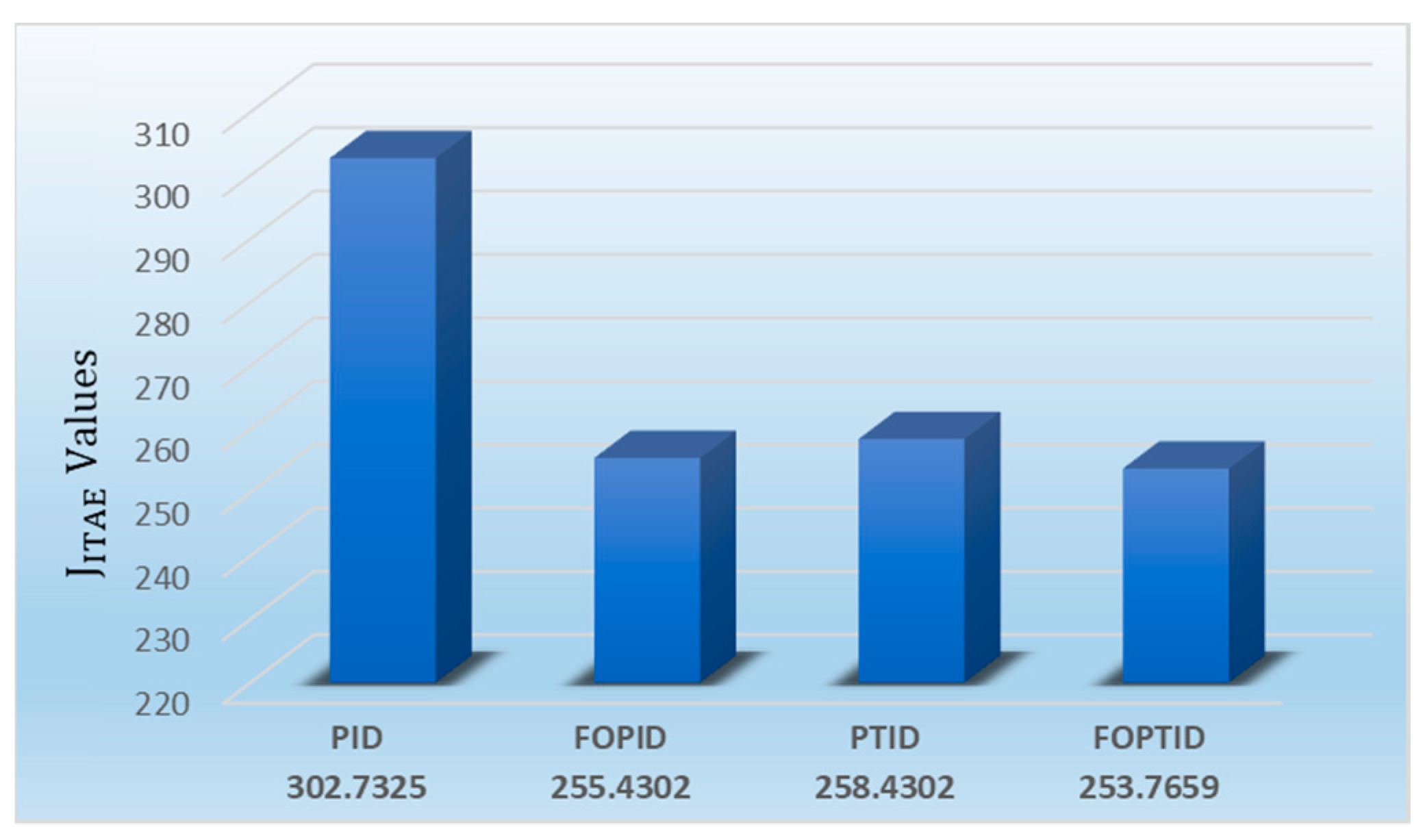
  • TID-based controllers, as well as PID-based controllers, have been tuned by GWO–PSO with minimization of the objective function J I T A E for the trajectory tracking control of the robot joints. Compared to the results from the tuned controllers, the proposed FOPTID control strategy achieved better performance than the other tuned controllers at the robot joints.
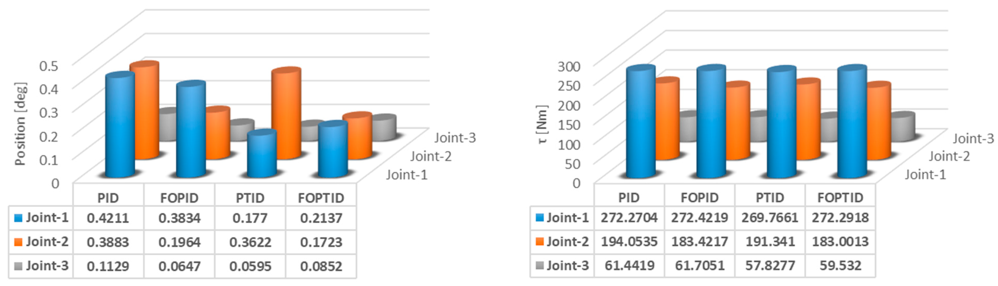
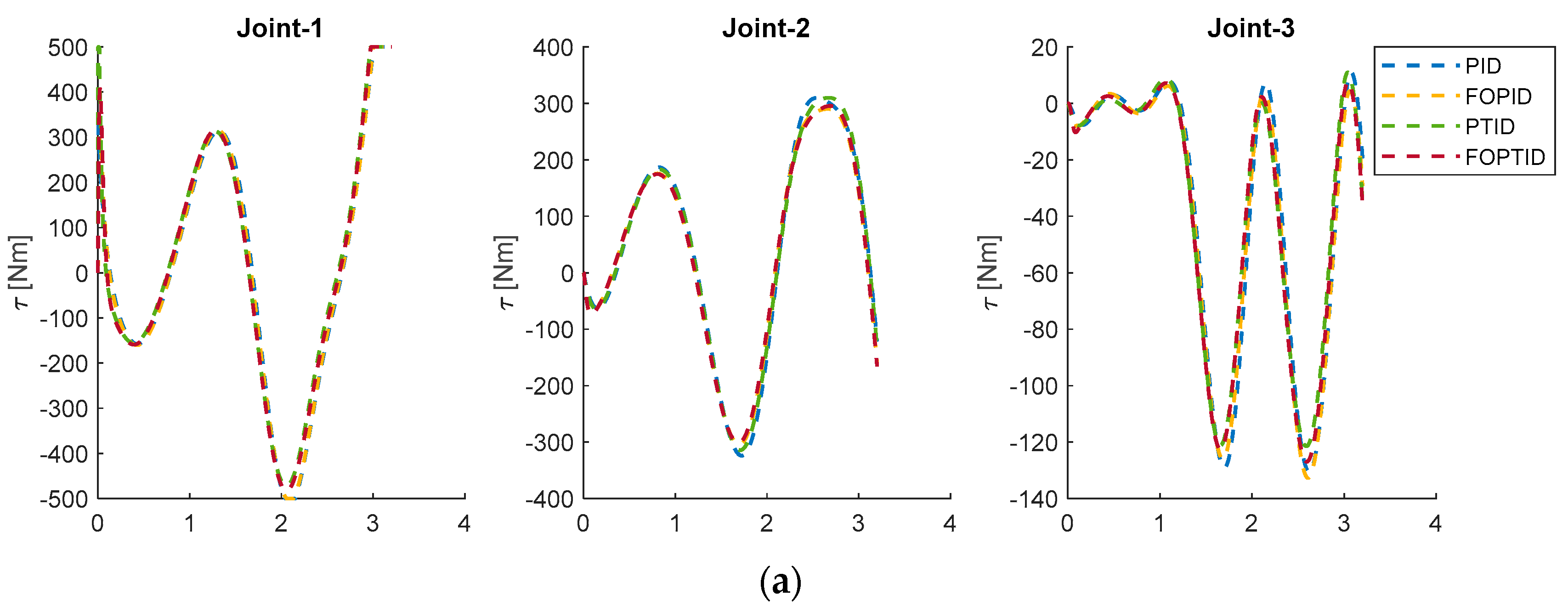
  • For the purpose of observing the stability of the designed controllers, a different trajectory was applied to the robot joints. The simulation results showed that PTID and FOPTID control schemes can track the change in the joint angle more accurately and maintain stability as compared to PID and FOPID control schemes. As well, TID-based controllers required lesser applied torque for tracking the desired joint trajectories than the PID based controllers.
  • As examined controller robustness in the presence of external disturbance applied to each joint, the proposed FOPTID controller was more capable of dealing with the disturbance in all joints during the reference trajectory tracking as compared to the PID, FOPID and PTID controllers. Accordingly, the effectiveness of the proposed controller was verified for disturbance rejection.
  • As compared to the designed controllers in terms of reducing the effect of joint friction, a remarkable performance was achieved by both PTID and FOPTID for a set point tracking task. From the simulation results, it could be inferred that the TID-based control schemes have significantly reduced the means of absolute joint errors.
TID-based control strategies, which have received a considerable amount of interest and attracted the attention of many researchers because of their potential advantages and applications in many fields, will be considered as future research on the control of a real robotic manipulator.

Funding

This research received no external funding.

Data Availability Statement

No data was used for the research described in the article.

Conflicts of Interest

The author declares no conflict of interest.

References

  1. Mirza, M.A.; Li, S.; Jin, L. Simultaneous learning and control of parallel Stewart platforms with unknown parameters. Neurocomputing 2017, 266, 114–122. [Google Scholar] [CrossRef]
  2. Oustaloup, A. From fractality to non-integer derivation through recursivity, a property common to these two concepts: A fundamental idea from a new process control strategy. In Proceedings of the 12th IMACS World Congress, Paris, France, 18–22 July 1998. [Google Scholar]
  3. Oustaloup, A.; Moreau, X.; Nouillant, M. The CRONE suspension. Control Eng. Pract. 1996, 4, 1101–1108. [Google Scholar] [CrossRef]
  4. Oustaloup, A.; Sabatier, J.; Lanusse, P. From fractal robustness to CRONE control. Fract. Calc. Appl. Anal. 1999, 2, 1–30. [Google Scholar]
  5. Podlubny, I. Fractional-Order Systems and Fractional-Order Controllers; Tech. Rep. UEF-03-94; Slovak Academy of Sciences Institute of Experimental Physics, Department of Control Engineering, University of Technology: Kosice, Slovakia, 1994. [Google Scholar]
  6. Bingul, Z.; Karahan, O. Fractional PID controllers tuned by evolutionary algorithms for robot trajectory control. Turk. J. Electr. Eng. Comput. Sci. 2012, 20, 1123–1136. [Google Scholar]
  7. Angel, L.; Viola, J. Fractional order PID for tracking control of a parallel robotic manipulator type delta. ISA Trans. 2018, 79, 172–188. [Google Scholar] [CrossRef]
  8. Al-Mayyahi, A.; Aldair, A.A.; Chatwin, C. Control of a 3-RRR Planar Parallel Robot Using Fractional Order PID Controller. Int. J. Autom. Comput. 2020, 17, 822–836. [Google Scholar] [CrossRef]
  9. Zhang, J.; Wang, Y.; Che, L.; Wang, N.; Bai, Y.; Wang, C. Workspace analysis and motion control strategy of robotic mine anchor drilling truck manipulator based on the WOA-FOPID algorithm. Front. Earth Sci. 2022, 10, 1253. [Google Scholar]
  10. Sharma, R.; Gaur, P.; Mittal, A.P. Performance analysis of two-degree of freedom fractional order PID controllers for robotic manipulator with payload. ISA Trans. 2015, 58, 279–291. [Google Scholar] [CrossRef]
  11. Dumlu, A.; Erenturk, K. Trajectory Tracking Control for a 3-DOF Parallel Manipulator Using Fractional-Order PIλDμ Control. IEEE Trans. Ind. Electron. 2014, 61, 3417–3426. [Google Scholar] [CrossRef]
  12. Lurie, B.J. Three-Parameter Tilt-Integral-Derivative (TID). U.S. Patent 5,371,670, 6 December 1994. [Google Scholar]
  13. Sain, D.; Swain, S.K.; Mishra, S.K. TID and I-TD controller design for magnetic levitation system using genetic algorithm. Perspect. Sci. 2016, 8, 370–373. [Google Scholar] [CrossRef] [Green Version]
  14. Sahu, R.B.; Panda, S.; Biswal, A.; Sekhar, G.T.C. Design and analysis of tilt integral derivative controller with filter for load frequency control of multi-area interconnected power systems. ISA Trans. 2016, 61, 251–264. [Google Scholar] [CrossRef] [PubMed]
  15. Gnaneshwar, K.; Padhy, P.K. Robust Design of Tilted Integral Derivative Controller for Non-integer Order Processes with Time Delay. IETE J. Res. 2021. [Google Scholar] [CrossRef]
  16. Bhuyan, M.; Das, D.C.; Barik, A.K.; Sahoo, S.C. Performance Assessment of Novel Solar Thermal-Based Dual Hybrid Microgrid System Using CBOA Optimized Cascaded PI-TID Controller. IETE J. Res. 2022. [Google Scholar] [CrossRef]
  17. Xue, D.; Chen, Y. A comparative introduction of four fractional order controllers. In Proceedings of the 4th World Congress on Intelligent Control and Automation, Shanghai, China, 10–14 June 2002; Volume 4, pp. 3228–3235. [Google Scholar]
  18. Morsali, J.; Zare, K.; Hagh, M.T. Comparative performance evaluation of fractional order controllers in LFC of two-area diverse-unit power system with considering GDB and GRC effects. J. Electr. Syst. Inf. Technol. 2018, 5, 708–722. [Google Scholar] [CrossRef]
  19. Topno, P.N.; Chanana, S. Differential evolution algorithm-based tilt integral derivative control for LFC problem of an interconnected hydro-thermal power system. J. Vib. Control 2018, 24, 3952–3973. [Google Scholar] [CrossRef]
  20. Sharma, M.; Prakash, S.; Saxena, S.; Dhundhara, S. Optimal fractional-order tilted-integral-derivative controller for frequency stabilization in hybrid power system using salp swarm algorithm. Electr. Power Compon. Syst. 2021, 48, 1912–1931. [Google Scholar] [CrossRef]
  21. Sharma, M.; Prakash, S.; Saxena, S. Robust Load Frequency Control Using Fractional-order TID-PD Approach via Salp Swarm Algorithm. IETE J. Res. 2021. [Google Scholar] [CrossRef]
  22. Lu, C.; Tang, R.; Chen, Y.Q.; Li, C. Robust tilt-integral-derivative controller synthesis for first-order plus time delay and higher-order systems. Int. J. Robust Nonlinear Control 2023, 33, 1566–1592. [Google Scholar] [CrossRef]
  23. Mohamed, E.A.; Ahmed, E.M.; Elmelegi, A.; Aly, M.; Elbaksawi, O.; Mohamed, A.A. An Optimized Hybrid Fractional Order Controller for Frequency Regulation in Multi-Area Power Systems. IEEE Access 2020, 8, 213899–213915. [Google Scholar] [CrossRef]
  24. Ahmed, E.M.; Mohamed, E.A.; Elmelegi, A.; Aly, M.; Elbaksawi, O. Optimum Modified Fractional Order Controller for Future Electric Vehicles and Renewable Energy-Based Interconnected Power Systems. IEEE Access 2021, 9, 29993–30010. [Google Scholar] [CrossRef]
  25. Choudhary, R.; Rai, J.N.; Arya, Y. Cascade FOPI-FOPTID controller with energy storage devices for AGC performance advancement of electric power systems. Sustain. Energy Technol. Assess. 2022, 53 Pt C, 102671. [Google Scholar] [CrossRef]
  26. Yanmaz, K.; Mengi, O.O.; Sahin, E. Advanced STATCOM Control with the Optimized FOPTID-MPC Controller. IETE J. Res. 2022. [Google Scholar] [CrossRef]
  27. Bingül, Z.; Karahan, O. Dynamic identification of Staubli RX-60 robot using PSO and LS methods. Expert Syst. Appl. 2011, 38, 4136–4149. [Google Scholar] [CrossRef]
  28. Ortigueira, M.D. Fractional Calculus for Scientists and Engineers; Springer: Berlin, Germany, 2011. [Google Scholar]
  29. Oustaloup, A.; Levron, F.; Mathieu, B.; Nanot, F.M. Frequency-band complex noninteger differentiator: Characterization and synthesis. IEEE Trans. Circuits Syst.-I Fundam. Theory Appl. 2000, 47, 25–39. [Google Scholar] [CrossRef]
  30. Hegedus, E.T.; Birs, I.R.; Ghita, M.; Muresan, C.I. Fractional-Order Control Strategy for Anesthesia–Hemodynamic Stabilization in Patients Undergoing Surgical Procedures. Fractal Fract. 2022, 6, 614. [Google Scholar] [CrossRef]
  31. Behera, M.K.; Saikia, L.C. Anti-windup filtered second-order generalized integrator-based spontaneous control for single-phase grid-tied solar PV-H2/Br2 redox flow battery storage microgrid system. J. Energy Storage 2022, 55B, 105551. [Google Scholar] [CrossRef]
  32. Ramoji, S.K.; Saikia, L.C. Optimal Coordinated Frequency and Voltage Control of CCGT-Thermal Plants with TIDF Controller. IETE J. Res. 2021. [Google Scholar] [CrossRef]
  33. Kennedy, J.; Eberhart, R.C. Particle swarm optimization. In Proceedings of the IEEE International Conference on Neural Networks, Perth, Australia, 27 November–1 December 1995; Volume IV, pp. 1942–1948. [Google Scholar]
  34. Mirjalili, S.; Mirjalili, S.M.; Lewis, A. Grey Wolf Optimizer. Adv. Eng. Softw. 2014, 69, 46–61. [Google Scholar] [CrossRef] [Green Version]
  35. Shaheen, M.A.M.; Hasanien, H.M.; Alkuhayli, A. A novel hybrid GWO-PSO optimization technique for optimal reactive power dispatch problem solution. Ain Shams Eng. J. 2021, 12, 621–630. [Google Scholar] [CrossRef]
  36. Valério, D.; Da Costa, J.S. NINTEGER: A non-integer control toolbox for MATLAB. In Proceedings of the Fractional Differentiation and Its Applications, Bordeaux, France, 19–20 July 2004. [Google Scholar]
Figure 1. The model of the first three links of Staubli RX-60 robot arm [27].
Fractalfract 07 00250 g001
Figure 2. FOPID controller structure.
Fractalfract 07 00250 g002
Figure 3. PTID controller structure.
Fractalfract 07 00250 g003
Figure 4. FOPTID controller structure.
Fractalfract 07 00250 g004
Figure 5. The updating process of velocity and position for each particle.
Fractalfract 07 00250 g005
Figure 6. Hierarchy of grey wolves.
Fractalfract 07 00250 g006
Figure 7. The position update process for grey wolves.
Fractalfract 07 00250 g007
Figure 8. Pseudo code of GWO–PSO.
Fractalfract 07 00250 g008
Figure 9. The schematic diagram of the proposed control system.
Fractalfract 07 00250 g009
Figure 10. Comparison of J I T A E values for PID, FOPID, PTID and FOPTID control strategies.
Fractalfract 07 00250 g010
Figure 11. Trajectory tracking performance of PID, FOPID, PTID and FOPTID controllers for each joint.
Fractalfract 07 00250 g011
Figure 12. Trajectory tracking performance in task and joint space for PID, FOPID, PTID and FOPTID controller schemes.
Fractalfract 07 00250 g012aFractalfract 07 00250 g012b
Figure 13. Joint position MAE values and control signal RMS values.
Fractalfract 07 00250 g013
Figure 14. Comparison of disturbance rejection abilities and MAE values of joint angle tracking based on the designed controllers.
Fractalfract 07 00250 g014
Figure 15. Joint tracking profiles and corresponding error profiles with respect to the presented controllers under friction.
Fractalfract 07 00250 g015
Figure 16. Comparison diagram of tracking error evaluation indicators based on J I T A E and MAE values for the presented controllers.
Fractalfract 07 00250 g016
Figure 17. Simulation results of the tuned controllers for the torques of each joint based on the different trajectory (a), disturbance rejection (b) and friction compensation (c) tests.
Fractalfract 07 00250 g017aFractalfract 07 00250 g017b
Table 1. Comparison of the optimized parameters of the controllers and MAE values for each joint.
JointController K t K p K i K d μ λ n MAE
1PID-203.87600.0127132.5981---2.0832
FOPID-271.49360.0124132.29611.03810.0756-1.9153
PTID236.3371349.75590.0122298.3974--299.98891.8705
FOPTID80.0347349.755921.2705273.05100.92570.3053268.39951.9048
2PID-325.01610.013079.4103---3.0791
FOPID-333.5564298.1256148.46131.09620.0308-3.0235
PTID298.125620.56040.013193.6091--233.82333.0426
FOPTID90.5690348.9735221.4909179.85751.05330.0104220.10782.9837
3PID-251.7546295.156625.5284---1.9342
FOPID-296.995180.5790311.03990.55490.6426-1.1130
PTID340.8880290.31040.012150.3965--132.38251.2832
FOPTID318.237429.38247.6325145.17910.65161.0140280.92491.1771
Table 2. Coulomb plus viscous friction model parameters.
Friction ParametersJoint-1Joint-2Joint-3Unit
F c 0.51.52.5Nm
F v 5.51.53.5Nm/(rad/s)
Table 3. RMS values of the control signals for robustness tests.
Robustness TestJointPIDFOPIDPTIDFOPTID
Different trajectoryJoint-1272.2704272.4219269.7661272.2918
Joint-2194.0535183.4217191.3410183.0013
Joint-361.441961.705157.827759.5320
Disturbance rejectionJoint-1173.1580154.1611158.5644157.0675
Joint-2328.8085267.0632245.4667241.7147
Joint-348.085539.809336.711235.8962
Friction compensationJoint-1110.4676122.6951124.7802134.4499
Joint-2184.6817141.4255143.2402141.6841
Joint-368.143099.272874.608793.4725
Disclaimer/Publisher’s Note: The statements, opinions and data contained in all publications are solely those of the individual author(s) and contributor(s) and not of MDPI and/or the editor(s). MDPI and/or the editor(s) disclaim responsibility for any injury to people or property resulting from any ideas, methods, instructions or products referred to in the content.

