Article

Multiple-Layer Image Encryption Utilizing Fractional-Order Chen Hyperchaotic Map and Cryptographically Secure PRNGs

1
Communications Department, Faculty of Information Engineering and Technology, German University in Cairo, Cairo 11835, Egypt
2
Computer Science Department, Faculty of Media Engineering and Technology, German University in Cairo, Cairo 11835, Egypt
*
Author to whom correspondence should be addressed.
Fractal Fract. 2023, 7(4), 287; https://doi.org/10.3390/fractalfract7040287
Submission received: 22 February 2023 / Revised: 19 March 2023 / Accepted: 23 March 2023 / Published: 26 March 2023

Abstract

:
Image encryption is increasingly becoming an important area of research in information security and network communications as digital images are widely used in various applications and are vulnerable to various types of attacks. In this research work, a color image cryptosystem that is based on multiple layers is proposed. For every layer, an encryption key and an S-box are generated and utilized. These are based on a four-dimensional (4D) dynamical Chen system of a fractional-order, the Mersenne Twister, OpenSLL, Rule 30 Cellular Automata and Intel’s MKL. The sequential application of Shannon’s ideas of diffusion and confusion three times guarantees a total distortion of any input plain image, thereby, resulting in a totally encrypted one. Apart from the excellent and comparable performance to other state-of-the-art algorithms, showcasing resistance to visual, statistical, entropy, differential, known plaintext and brute-force attacks, the proposed image cryptosystem provides an exceptionally superior performance in two aspects: a vast key space of 2 1658 and an average encryption rate of 3.34 Mbps. Furthermore, the proposed image cryptosystem is shown to successfully pass all the tests of the NIST SP 800 suite.

1. Introduction

The growing use of digital imaging technology and the increasing importance of online data storage and transmission have made research on image encryption both timely and necessary. In turn, this has also lead to increased demands for image-encryption algorithms in various aspects of life, including:
(a) Increased use of digital imaging technology and applications [1,2]. With the widespread use of digital cameras, smartphones and other imaging devices, the amount of sensitive and personal information stored in digital images has increased dramatically. This has made image encryption an important area of research.
(b) Growth of online data storage and transmission [3]. The increasing use of online data storage and transmission has made it easier for unauthorized parties to access confidential image data. This has made encryption an essential tool for protecting image data in transit and in storage.
(c) Threats to privacy and security [4]. As more sensitive and confidential information is stored in digital images, the risk of unauthorized access, theft and tampering has increased. Image encryption is needed to protect against these threats.
(d) Advancements in computing power [5]. As computing power continues to increase, attackers are able to use more sophisticated cryptanalysis methods to break encryption algorithms. This has made it important for researchers to continuously research and propose novel security measures for sensitive data.
While some researchers have focused their efforts into advancing cryptographic algorithms [6,7,8,9], others have dedicated their efforts towards the field of steganography [10,11]. Moreover, the literature shows a third group that combines the use of cryptography with steganography for added security [12,13,14]. Such efforts were realized because traditional data encryption algorithms, such as DES [15], 3DES [16] and AES [17,18] were found to be no longer best-suited for image encryption.
This is due to a number of reasons, such as (a) the large size of image data, which increases the computational cost and time required for encryption and decryption; (b) different properties of image data, such as redundancy, pixel-correlation and structure, which can affect the security of traditional encryption techniques; (c) lack of adaptability, since traditional encryption techniques are not well suited to handle the unique challenges posed by image data, such as the need to preserve image quality and the requirement for real-time encryption in certain applications; and (d) vulnerability to attacks, because some traditional encryption techniques, such as DES, have already been shown to be prone to cryptanalysis [19].
To that end, scientists and engineers have been making use of various mathematical constructs and ideas inspired by nature to design secure and robust image-encryption algorithms. The recent literature shows the employment of cellular automata (CA) [20,21,22], DNA coding [8,23,24,25], electric circuits [26,27] as well as heavy reliance on dynamical functions of chaotic behavior [6,28,29,30,31,32]. The following paragraph highlights the utilization of various such ideas in the development of pseudo-random number generators (PRNGs) to build encryption keys and substitution boxes (S-boxes).
The development and deployment of PRNGs comprise the majority of cryptography research efforts. This is because a randomly distributed bit stream benefits both key generation and S-box design [20]. Numerous examples in the literature illustrate the usage of PRNGs in image cryptosystems. The researchers in [33], for instance, employed the Lucas sequence to construct an S-box for their proposed image cryptosystem. The authors of [34] produced encryption keys using the Rossler chaotic system and a Recaman’s sequence. Likewise, the authors of [35] constructed PRNGs as encryption keys utilizing the Fibonacci sequence, a chaotic tan function and a Bessel function.
The researchers in [
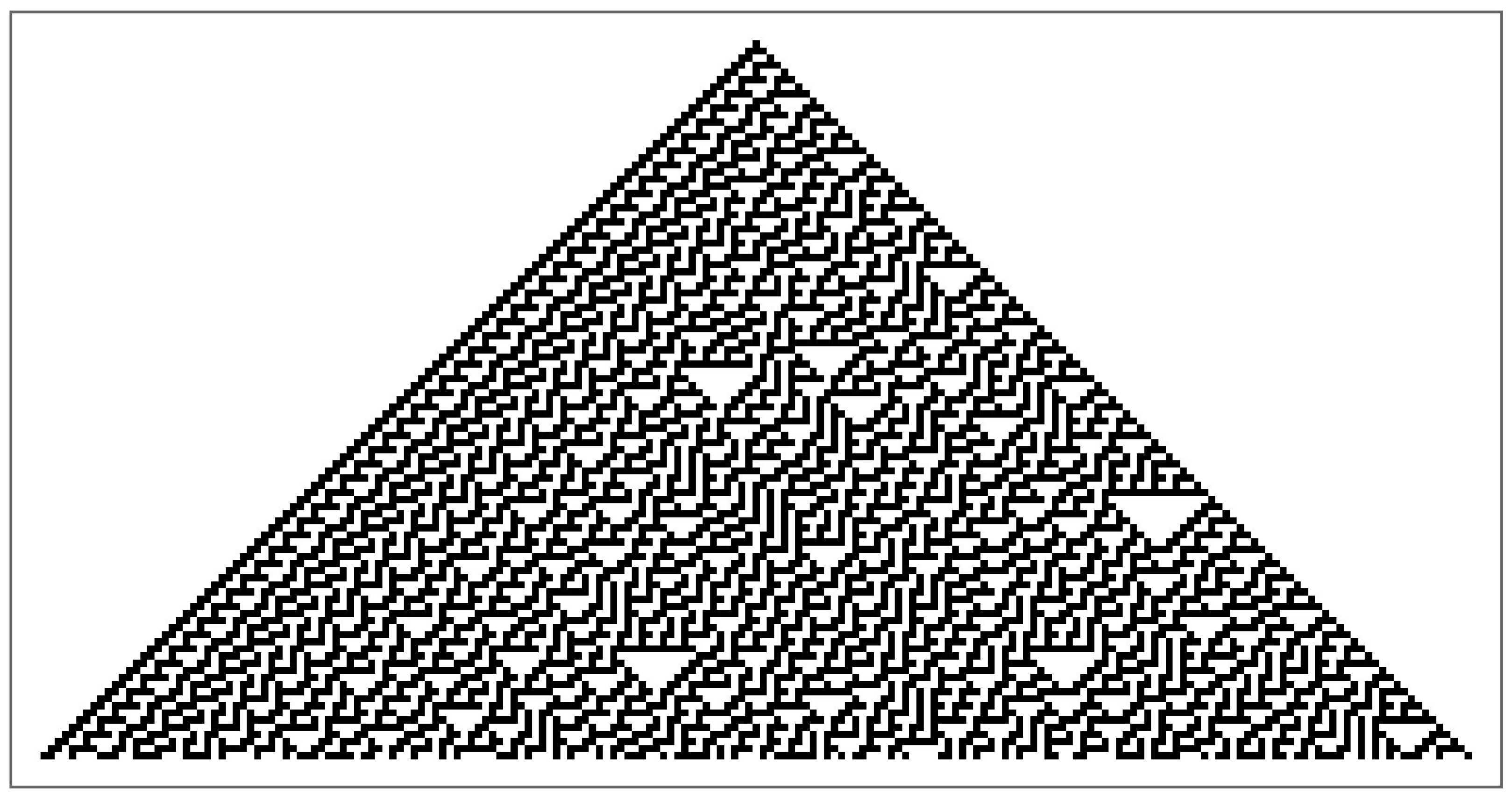
36] investigated elliptic curves and used them to create a PRNG, which they then combined with the Arnold map to encrypt images. Rule 30 CA generates a PRNG and was utilized as an encryption key in [20]. In [37], a field programmable gate array (FPGA) implementation of a PRNG utilizing a memristive Hopfield neural network with a specific activation gradient was proposed. The Mersenne Twister was deployed by the researchers in [7] as one of the encryption keys in a multi-stage cryptosystem. An S-box was designed and utilized as the core stage in a three-stage image cryptosystem in [8], where the Lorenz system was numerically solved, and its solution was used to generate a PRNG, which was then employed to generate the S-box.
In another multi-stage image cryptosystem, the authors of [38] employed a discretized version of the chaotic sine map to create an S-box and the hyperchaotic Lu system as a PRNG. On the other hand, thus far, the literature on image encryption does not feature image cryptosystems where the PRNGs offered by Intel’s Math Kernel Library (MKL) or OpenSSL are employed. Intel’s MKL is a library of optimized mathematical functions, including a high-quality PRNG [39]. It is specifically optimized for use on Intel hardware and can provide faster performance compared to other libraries, while OpenSSL is an open-source cryptography library that provides various cryptographic functions, including a random number generator [40].
The literature clearly shows that chaos theory has been extensively studied and applied to image cryptosystems. This is due to the diversity of desirable traits exhibited by dynamical functions of chaotic behavior. These traits include periodicity, pseudo-randomness, sensitivity to initial values and ergodicity [41]. Broadly, these functions are categorized as either low-dimensional (LD) or high-dimensional (HD) with each class having a set of exclusive advantages [6].
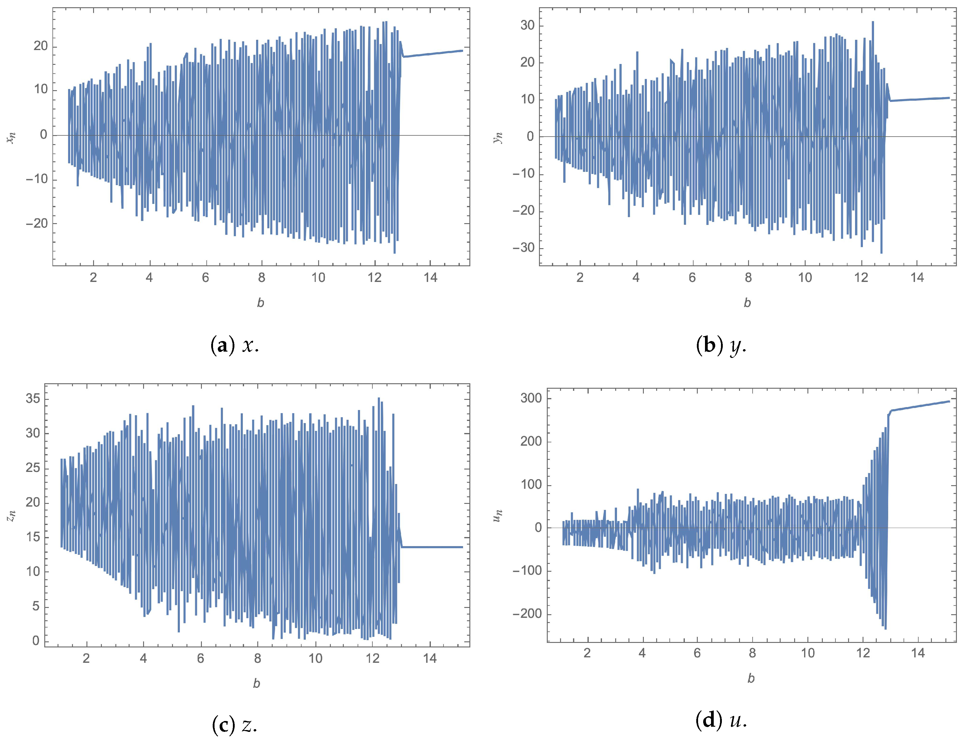
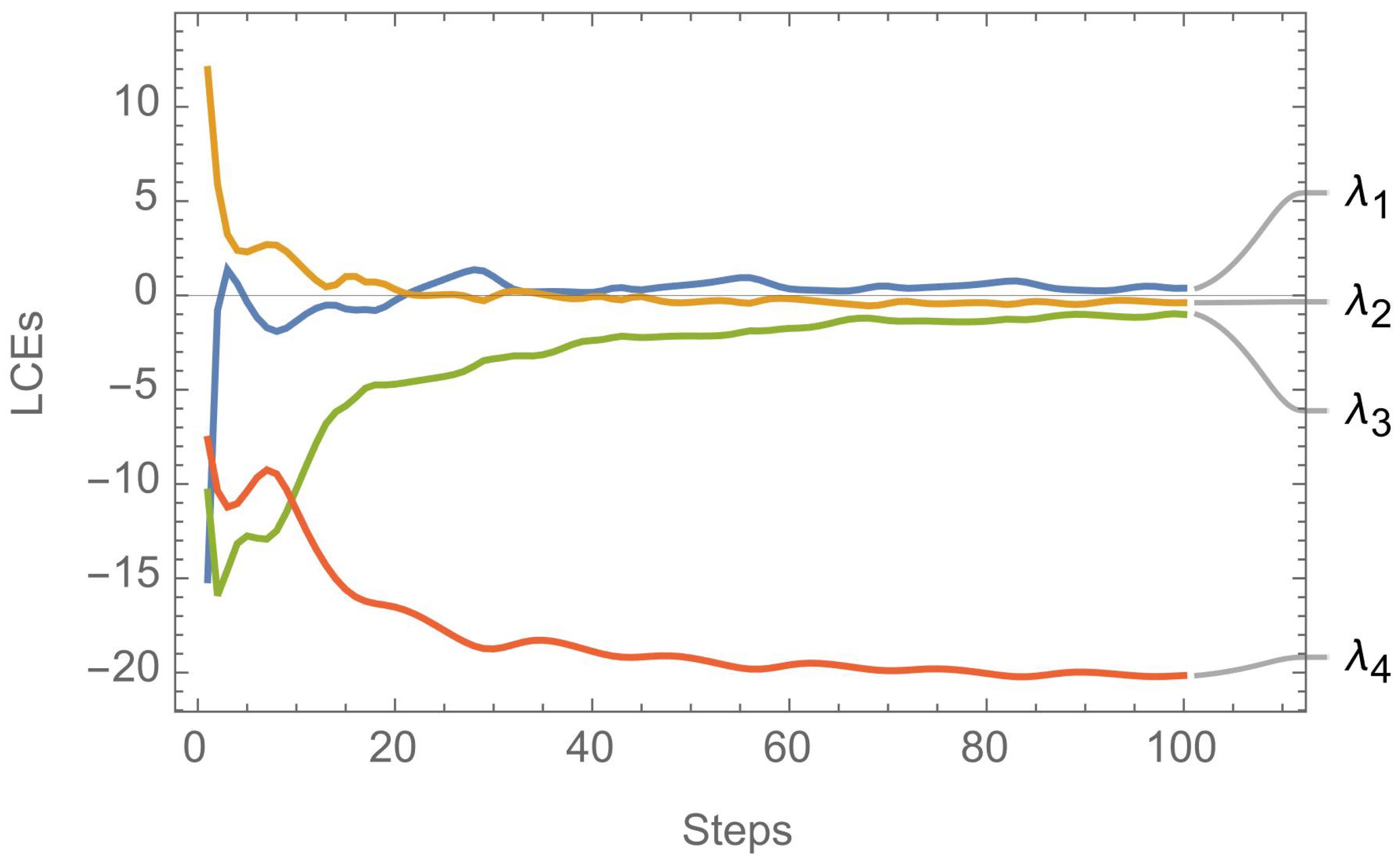
LD chaotic functions dramatically simplify software and hardware implementations; however, their use in image cryptosystems could, in some cases, be insufficiently secure. In contrast, HD chaotic functions, despite being more complex and needing more computational resources and circuitry, are capable of offering exceptionally high levels of security. Furthermore, upon studying hyperchaotic functions, a wide number of control parameters are readily apparent [42]. This implies that their use in image cryptosystems results in a significantly wider key space, which reduces the likelihood of brute-force attacks ever succeeding [8]. Attempting to solve hyperchaotic systems at a fractional-order permits a further expansion of the number of control variables and, consequently, an even wider key space.
Recently, the image processing community has developed an interest in chaotic fractional-order dynamical systems [43]. Specifically, their applications in image cryptosystems have gained traction due to their superior performance compared to their integer-order counterparts [44,45,46,47,48]. The authors of [44] proposed a secure image cryptosystem that employed smoothed sliding modes state observers for fractional-order chaotic systems. In [45], an image cryptosystem with a very large key space was proposed using a fractional-order four-dimensional (4D) Chen hyperchaotic map in conjunction with a Fibonacci Q-matrix.
An efficient image cryptosystem was proposed in [46], where various fractional-order systems were utilized in an alternating fashion. In [47], a fractional-order logistic map was proposed by the authors for the implementation of an image cryptosystem, where its performance was then compared to that attained by a conventional logistic map. The authors of [48] presented a technique for image encryption that used the solutions of chaotic fractional-order fuzzy cellular neural networks. However, it is easily observable that the use of fractional-order chaotic and hyperchaotic functions in image encryption makes for a rather new trend in the literature with only a few articles mentioning such an application.
The previous paragraphs aimed at describing the need for research on image cryptosystems, the reliance of scholars on PRNGs to generate encryption keys and robust S-boxes as well as the emerging utilization of hyperchaotic functions of fractional-order in this field of research. While the literature shows the prevalence of image cryptosystems that involve the use of multiple stages, in most cases, these are limited to only three stages that comprise a total of a permutation–substitution–permutation (as in [7,8,9,20,33]).
In the rare case of employing more stages, the execution times were not reported [45]. This is because of the increases in complexity and the need for longer execution times that result from adding further encryption stages. To make use of multiple-layer-encryption networks, while maintaining low complexity and short execution times, this research work proposes and achieves the following:
  • A highly efficient multiple layer image cryptosystem, where, in each layer, an encryption key is generated and utilized by XORing it with the image data, and then an S-box is generated and applied to the resulting image. This effectively allows for bit-diffusion and bit-confusion, thereby, satisfying Shannon’s theory for secure communications [49].
  • In the first layer, a fractional-order hyperchaotic Chen map is employed for key generation, while a Mersenne Twister PRNG is utilized for S-box design and application.
  • In the second layer, a Mersenne Twister PRNG is employed for key generation, while an OpenSSL PRNG is utilized for S-box design and application.
  • In the third layer, Rule 30 CA is employed for key generation, while an Intel’s MKL PRNG is utilized for S-box design and application.
  • By utilizing a dynamical system with hyperchaotic behavior as well as selecting three S-boxes with specific criteria, a very large key space of 2 1658 is achieved, thus, fending off brute-force attacks.
  • By optimizing the code efficiency, a superior encryption rate is achieved by the proposed image cryptosystem with an average encryption rate of 3.34 Mbps.
This paper is organized as follows. Section 2 presents the preliminary constructs and PRNGs utilized in the proposed image cryptosystem as well as the design and selection criteria for the S-boxes in use. Section 3 describes the proposed image cryptosystem in detail, along with algorithms and flow charts. Section 4 reports the attained numerical results and presents a comparative study with other state-of-the-art algorithms. Finally, Section 5 presents the conclusions of this research work and suggests plausible future research directions that could be further pursued.

2. Preliminary Mathematical Constructs

This section presents the various mathematical constructs that are employed in the proposed image cryptosystem for PRNG generation and S-box design. Next, a key-establishment protocol is proposed based on the performance evaluation metrics of the S-boxes.

2.1. The Fractional-Order Hyperchaotic Chen System

The fractional-order 4D Chen system [50,51] is a differential system, which falls under the hyperchaotic systems category. Hyperchaotic systems are systems of functions that are able to produce more than one positive Lyapunov exponent. In turn, this promotes the capability of producing more robust pseudo-random number sequences. Moreover, many control variables are involved in the Chen system due to being a 4D system of equations, which is beneficial for increasing the key space of the proposed image cryptosystem as a whole. Furthermore, the adopted Chen system in this work provides a good balance between high ergodicity, an improved distribution in phase space, as well as a tolerable computation complexity, as opposed to the Lorenz system [20] with its comparatively poor ergodicity or the hyperchaotic memristor circuit, which possesses transcendental nonlinearities but is highly complex in software implementations [52].
The Chen system is mathematically described as follows:
D α 1 x = a ( y x ) + u ,
D α 2 y = γ x x z + c y ,
D α 3 z = x y b z ,
and
D α 4 u = y z + d u .
In (1)–(4), 13 control variables are utilized to specify the system. The first four variables constitute the initial values for x, y, z and u (or x 0 , y 0 , z 0 and  u 0 ), which are the initial point in the 4D space. The second five variables, a, b, c, d and  γ , are the scale factors for the 4 equations. The last four variables, α 1 , α 2 , α 3 and  α 4 , are the fractional differential orders.
To visually illustrate the hyperchaotic behavior of the fractional-order 4D Chen system, Figure 1 displays example plots for the system. For demonstration purposes, the figure shows the solution of the regular system; nevertheless, in application, the system is further solved in fractional order. Further analysis of the system’s hyperchaotic behavior can be conducted through examining its bifurcation plots against various parameters, as illustrated in Figure 2 and Figure 3 for b and c, respectively. Moreover, the 4 Lyapunov characteristic exponents (LCEs), which give the rate of exponential divergence from perturbed initial conditions, are plotted in Figure 4.

2.2. The Mersenne Twister

The Mersenne Twister (MT) is a deterministic, high-quality PRNG algorithm. It was first introduced in 1997 by Makoto Matsumoto and Takuji Nishimura and is named after the French mathematician Marin Mersenne, who studied prime numbers [53]. The MT is considered to be one of the most advanced and widely used PRNG algorithms, and it is used in a variety of applications, including simulations, games and cryptography.
The MT generates random numbers by using a linear feedback shift register (LFSR), which is a simple mechanism for generating a sequence of binary numbers. The algorithm uses a specific mathematical formula to determine the next number in the sequence based on the current state of the LFSR and a constant seed value. The seed value is used to initialize the state of the LFSR, and it determines the entire sequence of numbers generated by the algorithm. The MT has several properties that make it an attractive choice for random number generation:
  • High-quality random numbers: The MT produces high-quality random numbers that are evenly distributed across the range of possible values. This makes it well-suited for use in simulations, games and other applications where randomness is important [54].
  • Large period: The MT has a very large period of 2 19937 1 , which means that the sequence of numbers generated by the algorithm is very long before it begins to repeat. This makes it useful for applications that require a large number of random numbers [53].
  • Fast generation: The MT is designed to be fast and efficient, and it can generate random numbers quickly, even on low-end hardware [55].
  • Easy to implement: The MT is easy to implement in a variety of programming languages and software (for example, MS Excel®, Mathworks Matlab® and Wolfram Mathematica®), which makes it accessible to a wide range of developers [56].

2.3. OpenSSL

OpenSSL is an open-source cryptography library that provides a wide range of cryptographic functions, including PRNG. The PRNG functionality in OpenSSL is designed to provide the fast and reliable generation of high-quality random numbers for use in a variety of applications, including simulations, games and cryptography. OpenSSL provides several different PRNG algorithms, including the Fortuna PRNG [57], which is a well-known and widely used PRNG. It also provides support for other PRNG algorithms, such as the Dual-EC-DRBG PRNG, which is designed for use in cryptographic applications. One of the key benefits of using OpenSSL for PRNG is its robustness and security.
Moreover, it is a widely used cryptography library that has undergone extensive security and performance testing, which makes it well-suited for use in security-sensitive applications, such as cryptography [58]. Additionally, the OpenSSL community is highly active and provides regular updates to the library, which helps to ensure that the PRNG algorithms in OpenSSL remain secure and reliable over time. OpenSSL also provides a comprehensive set of tools for controlling and configuring the PRNG, including the ability to set the seed value, specify the range of values to be generated and control the distribution of the random numbers. This makes it easy to use OpenSSL for PRNG in a variety of applications and to tailor it to the specific needs of each application.

2.3.1. Rule 30 Cellular Automata

Rule 30 is a one-dimensional (1D) binary CA—a type of CA that uses a grid of cells to generate patterns based on a set of simple rules. Each cell in the grid can be in one of two states, either “on” or “off”, and the state of each cell is determined based on the states of its neighbors according to the rule set. In the case of Rule 30, the rule set is simple: the state of a cell in the next generation is determined based on the states of its two neighbors in the current generation. Specifically, if the center cell is “off” and its two neighbors are both “on”, the center cell will be “on” in the next generation. If the center cell is “on” and its two neighbors are either both “on” or both “off”, the center cell will be “off” in the next generation.
The behavior of Rule 30 can be visualized as a pattern of “on” and “off” cells that evolves over time with each generation representing a new step in the evolution of the pattern. Figure 5 provides a graphical view of Rule 30 CA. Despite its simple rule set, Rule 30 exhibits a complex and seemingly random behavior with patterns that can be difficult to predict. Figure 6 demonstrates the application of Rule 30 to generate the first 10 steps, while Figure 7 demonstrates the application of Rule 30 to generate the first 100 steps.
Rule 30 has been the subject of extensive study by mathematicians and computer scientists, who have been fascinated by its complex behavior and the seemingly random patterns it generates. It has also been used in a variety of practical applications, including cryptography, as the seemingly random patterns generated by Rule 30 can be used as the basis for secure encryption algorithms.
For the sake of the proposed image cryptosystem; however, we are only interested in the simplest nontrivial CA in which a cell’s neighborhood is defined as the nearby cells on each side of it. Thus, any given cell, along with its two neighbors, would create a neighborhood of three cells, yielding 2 3 = 8 different patterns (as illustrated in Figure 5). More specifically, class three behavior is exhibited by rule 30 CA [20]. This indicates that simple input patterns result in chaotic and unpredictable outputs. Rule 30 CA mathematically determines the subsequent state of every cell through the following relation:
s i ( t + 1 ) = s i 1 ( t ) ( s i ( t ) + s i + 1 ( t ) ) ,
such that ⊕ and + on the RHS of (5) are, respectively, the XOR and OR logical operators. A PRNG is extracted from Rule 30 CA by examining the middle column of Figure 6 and converting every black cell into a 1 and every white cell into a 0. This means that the first 10 bits are { 1 , 1 , 0 , 1 , 1 , 1 , 0 , 0 , 1 , 1 } . In this work, we follow the technique proposed earlier in [33] to augment a seed in the generation procedure of the Rule-30-CA-based PRNG.

2.3.2. Intel’s Math Kernel Library

Intel’s Math Kernel Library (MKL) is a numerical library that provides a variety of mathematical functions and algorithms, including PRNG. The PRNG functionality in Intel MKL is designed to provide the fast and reliable generation of high-quality random numbers for use in a variety of applications, including simulations, games and cryptography. Intel’s MKL provides several different PRNG algorithms, including a parallel PRNG, which is designed to generate random numbers in a parallel fashion across multiple processing cores [59]. One of the key benefits of using Intel’s MKL for PRNG is its performance.
Intel’s MKL is optimized for Intel processors and can significantly improve the performance of random number generation compared to other PRNG algorithms. This makes it well-suited for applications that require large amounts of random numbers, such as Monte Carlo simulations or cryptography. Additionally, Intel’s MKL provides a comprehensive set of tools for controlling and configuring the PRNG, including the ability to set the seed value, specify the range of values to be generated and control the distribution of the random numbers. This makes it easy to use Intel’s MKL for PRNG in a variety of applications and to tailor it to the specific needs of each application.

2.3.3. S-Box Design

For the proposed image cryptosystem, a number of S-boxes were designed and employed to complete data confusion. This was performed by applying the following steps:
1.
Assume a pseudo-randomly generated bit stream b P R N G of a sufficiently long length L P R N G .
2.
Divide b P R N G into N shorter bit streams b P R N G i , i [ 1 , N ] of length L P R N G / N each.
3.
Partition every bit stream b P R N G i into groups of 8 bits each.
4.
Convert every group of 8 bits into a decimal number. This results in a list with elements e j [ 0 , 255 ] .
5.
Eliminate duplicates, such that the list only has 256 unique elements spanning [ 0 , 255 ] . In case the size of the resulting list is less than 256, this list is discarded.
6.
Repeat the above steps for the other N 1 bit streams, obtaining a maximum of N S-boxes.
7.
For the (possibly) N S-boxes, assume a set of target performance metrics, where each S-box is evaluated using the same performance evaluation metrics, and the selected S-box is the one closer (in performance values) to the target metrics.
This procedure is provided as an algorithm in Algorithm  2.

2.3.4. Key-Establishment Protocol

Since the image cryptosystem that is proposed in this research work adopts symmetric-key cryptography, it is essential for both the transmitting and receiving parties to have the same sets of keys. While the first set of keys includes those that are used as seed values for the various aforementioned PRNGs, as in the vast majority of image encryption literature, these must be pre-shared over a secure channel prior to the exchange of any sensitive data (i.e., the encrypted images). However, the second set of keys, which relates to the generation and design of S-boxes, will not take on the traditional form. These will actually be based on pre-shared specific values of S-box performance metrics.
In Section 2.3.3, with an arbitrary PRNG bit stream, it was shown how N S-boxes could be obtained. For any S-box, a number of performance evaluation metrics may be computed and utilized to assess its cryptographic properties and strength. Those metrics are described in Section 4.13, and their ideal values are provided in Table 19. In this research work, we propose the communicating parties to agree on a specific set of values for the performance evaluation metrics of the S-boxes to be utilized. This means that receiver will generate N S-boxes, compute their metrics and then select the S-box with identical performance evaluation metrics to those pre-shared by the transmitter. Implementing such a protocol has a number of implications as follows:
1.
It vastly increases the key space of the image cryptosystem, since every S-box in use has five metrics. In the proposed image cryptosystem, three S-boxes are employed. This leads to the introduction of 3 × 5 = 15 new variables as part of the key and, thus, a giant leap in resistivity to brute-force attacks.
2.
Using a single arbitrary PRNG bit stream of sufficiently long length L P R N G , many S-boxes can be generated and applied. Their use can be varied for subsequent transmissions, thus, increasing the complexity of any cryptanalysis efforts.
3.
However, instead of generating a number of S-boxes and only selecting that with the best-performing set of metrics, near-optimum S-boxes would be employed. Nevertheless, this limitation is superseded by the fact that each of the utilized S-boxes is only a single component of a larger multiple-layer-encryption network. Thus, the performance of the encryption network, as a whole, is what really matters.

3. Proposed Image Cryptosystem

Section 3.1 outlines the encryption process, while Section 3.2 outlines the decryption process. This is followed by the algorithms utilized in each of them as outlined in Section 3.3.

3.1. The Encryption Process

The proposed image cryptosystem can be outlined through the following steps:
1.
A plain RGB image I of dimensions M × N is selected and its pixels are converted into a 1D bit stream of plaintext data bits d with length L d .
2.
Encryption Layer 1: Chen encryption key and Mersenne Twister S-box.
(a)
The hyperchaotic Chen system of fractional-order is solved, and an encryption key k C h e n is generated from its solution using Algorithm 1. The length L d of this key is given by
L d = M × N × 3 × 8 .
(b)
An encryption process is applied, where the plaintext data bits d are XORed with the first encryption key k C h e n as follows:
d 1 = d k C h e n .
(c)
The bit stream d 1 is reshaped back into an image I 11 .
(d)
Algorithm 2 is applied to the Mersenne Twister PRNG, obtaining a Mersenne-Twister-based S-box S M T , such as that displayed in Table 1.
(e)
A pixel value substitution process is applied on image I 11 using S M T and obtaining image I 12 as follows:
I 12 = S M T ( I 11 ) .
(f)
The pixels of the encrypted image I 12 are converted into a 1D bit stream d 12 .
3.
Encryption Layer 2: Mersenne-Twister encryption key and OpenSSL S-box.
(a)
A Mersenne-Twister-based encryption key k M T is generated with length L d .
(b)
An encryption process is applied, where the bits of the encrypted image d 12 are XORed with the second encryption key k M T as follows:
d 21 = d 12 k M T .
(c)
The encrypted data bits d 21 are reshaped back into an image I 21 .
(d)
Algorithm 2 is applied to the OpenSSL PRNG, obtaining an OpenSSL-based S-box S O p e n S S L , such as that displayed in Table 2.
(e)
A pixel value substitution process is applied on image I 21 using S O p e n S S L and obtaining image I 22 as follows:
I 22 = S O p e n S S L ( I 21 ) .
(f)
The pixels of the encrypted image I 22 are converted into a 1D bit stream d 22 .
4.
Encryption Layer 3: Rule-30-CA encryption key and Intel’s MKL S-box.
(a)
A Rule-30-CA-based encryption key k C A is generated with length L d .
(b)
An encryption process is applied, where the bits of the encrypted image d 22 are XORed with the third encryption key k C A as follows:
d 3 = d 22 k C A .
(c)
The encrypted data bits d 3 are reshaped back into an image I 31 .
(d)
Algorithm 2 is applied to Intel’s MKL PRNG, obtaining an Intel’s MKL-based S-box S M K L , such as that displayed in Table 3.
(e)
A pixel value substitution process is applied on image I 31 using S M K L and obtaining the final encrypted image I 32 as follows:
I 32 = S M K L ( I 31 ) .
Figure 8 displays a flow chart for the encryption process comprising all the layers.

3.2. The Decryption Process

The decryption process takes the form of the inverse of the encryption process. It can be outlined in a number of steps as follows—through applying each of the layers in a reverse order:
1.
Starting with the final encrypted image I 32 of dimensions M × N .
2.
Decryption Layer 3: Intel MKL’s S-box and Rule-30-CA encryption key.
(a)
A reverse pixel value substitution process is applied on image I 32 using S M K L 1 and obtaining image I 31 as follows:
I 31 = S M K L 1 ( I 33 ) .
(b)
The pixels of the encrypted image I 31 are converted into a 1D bit stream d 3 .
(c)
A decryption process is applied, where the data bits d 3 are XORed with the third encryption key k C A as follows:
d 22 = d 3 k C A .
(d)
The encrypted data bits d 22 are reshaped back into an image I 22 .
3.
Decryption Layer 2: OpenSSL S-box and Mersenne-Twister encryption key.
(a)
A reverse pixel value substitution process is applied on image I 22 using S O p e n S S L 1 and obtaining image I 21 as follows:
I 21 = S O p e n S S L 1 ( I 22 ) .
(b)
The pixels of the encrypted image I 21 are converted into a 1D bit stream d 2 .
(c)
A decryption process is applied, where the data bits d 2 are XORed with the second encryption key k M T as follows:
d 12 = d 2 k M T .
(d)
The encrypted data bits d 12 are reshaped back into an image I 12 .
4.
Decryption Layer 1: Mersenne-Twister S-box and Chen hyperchaotic fractional-order encryption key.
(a)
A reverse pixel value substitution process is applied on image I 12 using S M T 1 and obtaining image I 11 as follows:
I 11 = S M T 1 ( I 12 ) .
(b)
The pixels of the encrypted image I 11 are converted into a 1D bit stream d 1 .
(c)
A decryption process is applied, where the encrypted data bits d 1 are XORed with the first encryption key k C h e n as follows:
d = d 1 k C h e n .
(d)
The plaintext data bits d are reshaped back into a plain RGB image I.
Figure 9 displays a flow chart for the decryption process comprising all the layers in a reverse order.

3.3. Utilized Algorithms

Algorithm 1 describes the generation of a PRNG from a chaotic system. Algorithm 2 describes the generation of an S-box given a pseudo-random bit stream generated using one of the three proposed PRNGs suggested earlier in Section 2. As discussed in Section 2.3.3, given a sufficiently long bit stream, a number of S-box trials and a set of target performance metrics, Algorithm 2 aims at finding an S-box that is as close as possible to the provided performance metric values. It may seem counter-intuitive to provide a set of less-than-optimal performance metric values to such an algorithm; however, a near-optimal S-box can be considered as sufficient for a sub-routine in a large-scale image cryptosystem in addition to reducing the predictability factor (as a cryptanalyst would assume that an optimal S-box must be applied).
Algorithm 1 Generate a PRNG bit stream given a chaotic system S of k dimensions and the number of needed bits n
1.
Solve S for the size of n k + 1 generating the set of lists { L 1 , L 2 , , L k }
2.
Flatten the set of lists into one list L = { L 1 [ 1 ] , L 2 [ 1 ] , , L k [ 1 ] , L 1 [ 2 ] , L 2 [ 2 ] , , L k [ 2 ] , }
3.
If | L | > n , drop the last | L | n elements from L
4.
λ = M e d i a n ( L )
5.
Return L b i t s | L b i t s [ i ] = 1 , if L [ i ] > λ 0 , otherwise
Algorithm 2 Generate an S-box given a bit stream b P R N G , the number of S-box trials n and target performance metric values M = { N L , S A C , B I C , L A P , D A P }
1.
S b i t s = { b P R N G 1 , b P R N G 2 , , b P R N G n } | i = 1 n ( b P R N G i ) = b P R N G
2.
S S b o x = []
3.
For each S j S b i t s :
(a)
W j = P a r t i t i o n ( S j , 8 ) , creating a list of lists of bits of dimensions L × 8
(b)
Z j = i = 1 L ( T o D e c i m a l ( W j i ) )
(c)
S b o x j = R e m o v e D u p l i c a t e s ( Z j )
(d)
Evaluate S b o x j creating M j = { N L j , S A C j , B I C j , L A P j , D A P j }
(e)
A p p e n d ( { S b o x j , M j } , S S b o x )
4.
S b o x r e s = S s b o x ( 1 , 1 )
5.
S b o x D i f f = M a g n i t u d e ( M S s b o x ( 1 , 2 ) )
6.
For each { S b o x j , M j } S s b o x :
(a)
S b o x D i f f j = M a g n i t u d e ( M M j )
(b)
If ( S b o x D i f f j < S b o x D i f f ) :
i.
S b o x D i f f = S b o x D i f f j
ii.
S b o x r e s = S b o x j
7.
Return S b o x r e s

4. Numerical Results and Performance Evaluation

This section aims at conducting a full performance evaluation analysis of the proposed image cryptosystem as well as at performing a comparative study with other state-of-the-art image-encryption algorithms. The conducted analyses will test the proposed image cryptosystem’s ability to fend off attacks of various natures. Those include visual, statistical, entropy and differential as well as brute-force attacks.
We further measure how wide the key space is, how fast the cryptosystem performs image encryption and decryption and whether it can successfully pass all the tests in the National Institute of Standards and Technology (NIST) test suite. The proposed image cryptosystem and its testing were implemented in the Wolfram language, utilizing Wolfram Mathematica® v.13.2. This was performed on a machine with the following specifications: 2.9 GHz 6-Core Intel® CoreTM i9 and 32 GB of 2400 MHz DDR4 RAM, running on macOS Catalina v.10.15.7.
A number of commonly utilized images from the image processing community were employed. These include Lena, Mandrill, Peppers, Sailboat, House, House2 and Tree, all of dimensions 256 × 256 , unless otherwise specified. The following subsections present the results of each of the conducted tests.

4.1. Human Visual System Examination and Histogram Analysis

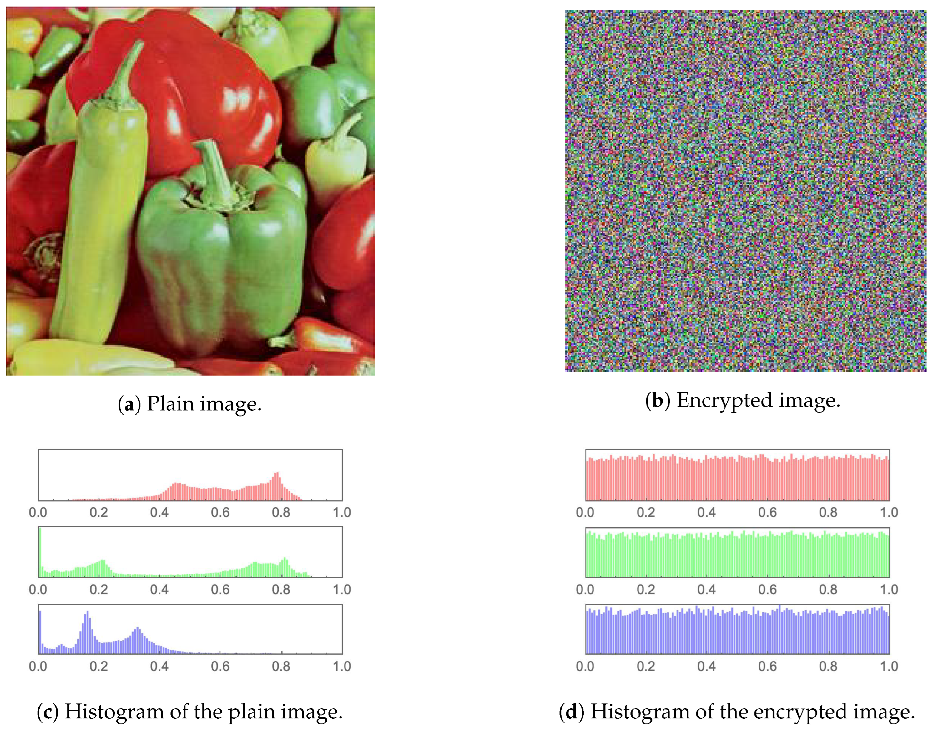
The simplest performance evaluation of an image cryptosystem may be easily conducted by examining a plain image and its encrypted version employing the human visual system (HVS). Figure 10, Figure 11, Figure 12, Figure 13, Figure 14 and Figure 15 (including sub-figures) showcase a number of plain images and their encrypted versions as obtained through the application of the proposed image cryptosystem. It is clear that no visual cues can be attained from the encrypted images as to what their plain versions could be.
Furthermore, by incorporating a statistical measure, the histograms of the plain images and their encrypted versions, which are provided in the same set of figures, also showcase excellent performance. While the histograms of every plain image clearly depict unique statistical characteristics, those of the encrypted images show an almost uniform distribution, which cannot be traced back to any specific plain image. This signifies the ability of the proposed image cryptosystem to fend off attacks of a statistical nature.

4.2. Mean Squared Error

The mean squared error (MSE) between two images is a widely used performance evaluation metric for image-encryption algorithms. It is a measure of the difference between a plain image and its encrypted version. The purpose of any image cryptosystem is to scramble the image data in such a way that it becomes extremely difficult for an unauthorized third-party to access the original plain image. To evaluate the effectiveness of an image cryptosystem, it is thus necessary to compare the encrypted image with the plain image and to measure the difference between them.
The MSE is one of the most common methods of achieving this. It is basically a scalar value that measures the average of the squared difference between the pixel values of two images. The smaller the MSE value, the more similar the two images are. In image encryption, the goal is to encrypt the image in such a way that the encrypted image is as different from the original image as possible, while still being able to decrypt it back to its original form.
A high MSE value between a plain image and its encrypted version indicates that the encryption process has been successful. The MSE is calculated as follows: Given two images I and I with the same dimensions M × N , the MSE is calculated by summing the squared difference between each corresponding pixel in the two images and then dividing by the total number of pixels in the image. Mathematically, it is expressed as:
M S E = i = 0 M 1 j = 0 N 1 ( I ( i , j ) I ( i , j ) ) 2 M × N .
Table 4 displays the computed MSE values for different images. It also provides a comparison with other image cryptosystems in the state-of-the-art. It is shown that comparable performance is attained.
It is common to report the MSE and peak signal-to-noise ratio (PSNR) values jointly upon assessing image cryptosystems. This is usually performed since the computation of PSNR is based on the value of MSE. Nevertheless, the authors of [60] only provided PSNR values without reporting MSE values. This is the reason Table 4 shows columns of N/A under the heading of [60].

4.3. Peak Signal-to-Noise Ratio

The peak signal-to-noise ratio (PSNR) is based on the MSE discussed in Section 4.2. It aims to connect the error margin to the peak value of a given signal. In this research work, such a peak signal value is determined as the highest pixel intensity in an image ( I m a x = 255 ). Therefore, for a given image I, the PSNR is mathematically expressed as:
P S N R = 10 log I m a x 2 M S E .
It is clear in (20) that the PSNR is inversely proportional to the MSE. Thus, the lower the PSNR value, the better. Table 5 displays the computed PSNR values for the image cryptosystem proposed in this work as well as those reported in the literature by counterpart algorithms. It is clear that the achieved PSNR values are comparable to the state-of-the-art.

4.4. Mean Absolute Error

The mean absolute error (MAE ) between a plain image and its encrypted version refers to the average difference between the intensity values of corresponding pixels in the two images. It represents the average magnitude of the differences between the original and encrypted pixels and is a measure of the quality of the encryption process in terms of preserving the visual information of the original image. The higher the MAE, the greater the difference of the encrypted image to the original plain image in terms of the pixel intensity values and the better the image cryptosystem is at distorting the original plain image information. It is represented mathematically as:
M A E = i = 0 M 1 j = 0 N 1 | I ( i , j ) I ( i , j ) | M × N ,
where I and I are two images. Table 6 displays the computed MAE values for the proposed image cryptosystem in comparison to other state-of-the-art algorithms. It is clear that the achieved MAE values are comparable to the state-of-the-art.

4.5. Information Entropy

In the realm of grayscale images, Shannon’s information entropy is used to quantify the randomness of an image’s gray pixel value distribution. According to Shannon’s theory, the formula for calculating information entropy is:
H ( m ) = i = 1 M p ( m i ) log 2 1 p ( m i ) ,
where p ( m i ) is the probability of occurrence of symbol m, while M is the total number of bits for each symbol. In relation to images, as a grayscale image has 256 distinct values [ 0 255 ] and 2 8 potential permutations, the entropy value of an encrypted image reaches a maximum of 8. Consequently, the entropy can be used to measure the unpredictability of encrypted images. In Table 7, the entropy values computed for the image cryptosystem proposed in this work as well as other state-of-the-art algorithms are displayed. It is clear that the entropy values computed for the various images are extremely close to the ideal value of 8, indicating that the proposed image cryptosystem is resistant to entropy attacks. Moreover, the disparities in the information entropy values for the state-of-the-art are demonstrated to be insignificant.

4.6. Fourier Transformation Analysis

The discrete Fourier transform (DFT) is a mathematical technique that transforms a discrete signal into its equivalent frequency representation. In the context of image encryption, DFT can be used as a tool for analyzing the frequency content of an image. In order to transform an image from the spatial domain to the frequency domain, the following expression mathematically describes the application of DFT:
F ( k , l ) = i = 0 N 1 j = 0 N 1 f ( i , j ) e i 2 π ( k i N + l i N ) ,
such that f ( a , b ) is the spatial domain representation of the image, where the exponential term is the basis function corresponding to each point F ( k , l ) in the Fourier space. When applied to a plain image, the DFT separates the image into its constituent frequencies, which can be visualized as peaks in the frequency spectrum. This representation is useful for analyzing the image structure, as certain patterns and features can be identified by the presence of specific frequencies. On the other hand, when applied to an encrypted image, the result is a transformed representation of the encrypted data. However, this transformed representation typically does not provide any useful information about the original image.
The encrypted data has been altered in a way that makes it difficult to extract any meaningful information—even after transforming it. The aim of any image cryptosystem is to render image content unintelligible, and DFT can help confirm this by showing that the transformed representation of the encrypted image is not representative of the original data. Figure 15b,e display the DFT as applied to the plain Tree image and its encrypted version, respectively. Unlike the various special features, such as edges and corners, which result in the plus-sign-shape of the DFT of the plain image, the DFT of its encrypted version is distorted and lacks any such features.

4.7. Correlation Coefficient Analysis

This assessment approach evaluates the consistency of a single image. The objective of such an evaluation metric is to assess the cohesiveness of pixels in close proximity. This means that the aim here is to calculate the proportion of uniform regions relative to edge transitions. As a result, a rather high correlation coefficient (i.e., co-occurrence) value is anticipated in the case of plain images, which consist of more regions than edges. Alternatively, as substantial distortion is desired in encrypted images, a lower correlation coefficient is expected. The following set of equations mathematically describe how the pixel cross-correlation coefficient ρ is computed:
ρ ( x , y ) = c o v ( x , y ) σ ( x ) σ ( y ) ,
where
c o v ( x , y ) = 1 N i = 1 N ( x i μ ( x ) ) ( y i μ ( y ) ) ,
σ ( x ) = 1 N i = 1 N ( x i μ ( x ) ) 2 ,
and
μ ( x ) = 1 N i = 1 N ( x i ) .
Classically, this metric is computed for three directions: horizontal, vertical and diagonal, where an image with a strong pixel cross-correlation would typically yield a value close to 1. On the other hand, for a well-encrypted image, its pixel cross-correlation would typically yield a value close to 0. Such values are well-exemplified in Table 8, where the pixel correlation coefficients are computed and displayed for various plain images and their encrypted versions, each in three directions. Moreover, Table 9 and Table 10 provide numerical comparisons with other state-of-the-art algorithms of the pixel correlation coefficients for the Lena image both in RGB format and for each of the separate color channels.
In addition to the numerical analysis offered by computing (24)–(27), the co-occurrence matrix can be shown to visualize directional covariance. In the case of images with natural visual characteristics, there is a higher probability for values with high similarity to coexist, leading to magnitudes within the matrix to mostly exhibit a linear distribution. In contrast, for a well-encrypted image, a more uniform distribution of values is expected. To visually illustrate this, Figure 16 provides 2D plots of the pixel co-occurrence matrices for the plain and encrypted Tree image in three directions.
Clearly, sub-figures (a), (b) and (c) are diagonal in nature, reflecting strong pixel correlation in the plain image, unlike sub-figures (d), (e) and (f), which reflect a rather uniform distribution, signifying random pixel values. Not surprisingly, the same pixel correlation behavior is noticed for each of the separate color channels of the Tree image, which are illustrated in Figure 17, Figure 18 and Figure 19. Moreover, a similar 3D plot of the same metric is illustrated in Figure 15, where sub-figures (c) and (f) provide pixel correlation for the plain and encrypted Tree images, respectively.

4.8. Differential Attack Analysis

This analysis evaluates the quality of an image-encryption algorithm based on the difference between the plain and encrypted images. This is conducted as follows. An input plain image is compared to its encrypted version on a pixel-by-pixel basis. Such a computation is performed to reach a percentage indicating the change in color intensities resulting from the encryption procedure. Since an absence of resemblance between comparable pixels in both images is promoted, such an evaluation must be performed pixel-by-pixel.
In addition, a more general aspect of the aggregate pixel change rates between images is analyzed, indicating the presence of prevailing color intensity similarities between these images. The literature suggests two tests to satisfy these requirements: the number of pixel change ratio (NPCR) for pixel-by-pixel comparison and the unified averaged change intensity (UACI) for the evaluation of the mean average difference.
The NPCR signifies the percentage evaluation of the number of altered pixels. Such a difference among pixels is performed with a stern equality stance. For two images, I 1 and I 2 (of dimensions M × N ), the difference per pixel D ( x , y ) (where x and y are the coordinates of the pixel) is equated as:
D ( x , y ) = 0 I 1 ( x , y ) = I 2 ( x , y ) 1 O t h e r w i s e x [ 1 , M ] & y [ 1 , N ] .
Thus, the NPCR is mathematically expressed as:
NPCR = x = 1 M y = 1 N D ( x , y ) M × N × 100 .
This means that a larger percentage reflects a more significant difference between the two images. As a significant difference is sought, the state-of-the-art suggests that 99 % is the target NPCR value for a well-encrypted image.
Utilizing a different assessment lens, the UACI attempts to assess the difference between two images with regard to their mean averages. The UACI is mathematically expressed as:
UACI = 1 M × N x = 1 M y = 1 N | I 1 ( x , y ) I 2 ( x , y ) | 255 × 100 .
The state-of-the-art considers an ideal value of about 33 % to reflect a well-encrypted image (with respect to the color range [ 0 , 255 ] , 33 % is approximated to 85 steps of difference in intensity.)
For the proposed image cryptosystem, Table 11 displays the computed NPCR and UACI values for different images with average values corresponding to 99.6119 % and 31.4563 % , respectively, indicating very good NPCR and UACI performance. Furthermore, Table 12 presents a comparison with the literature for the three separate color channels for various images. A comparable performance is shown. Finally, Table 13, provides another comparison with the literature for the RGB Lena image. Furthermore, here, comparable performance is attained.

4.9. The National Institute of Standards and Technology Analysis

The National Institute of Standards and Technology (NIST) Special Publication (SP) 800 series provides guidelines, standards and best practices for various aspects of information security, including image encryption [69]. The NIST SP 800 series is widely recognized as a leading source of information security guidance and is widely used by organizations in the public and private sectors. In relation to image encryption, NIST SP 800-60 provides guidelines for the selection and use of image-encryption algorithms. The publication provides a framework for evaluating and comparing different encryption algorithms based on factors, such as security, performance and implementation complexity.
The guidelines in SP 800-60 are intended to help organizations choose the most appropriate encryption algorithm for their specific needs and to ensure the security and privacy of encrypted images. Moreover, the NIST SP 800-63-3 provides guidelines for the secure use of biometric images, such as fingerprints, iris scans and facial recognition data. These guidelines cover various aspects of biometric image security, including the secure storage, transmission and use of biometric images. Furthermore, those specific guidelines in SP 800-63-3 are intended to help organizations protect the confidentiality, integrity and availability of biometric images, while also addressing privacy concerns. This makes it of paramount importance to include a NIST analysis as part of the performance evaluation of any image cryptosystem.
The NIST analysis suite of tests assesses a bit stream for randomness through various tests. For such a bit stream to successfully pass all the tests, it needs to score a p-value of at least 0.01 in all of them. Upon performing a NIST analysis on encrypted bit streams resultant from the proposed image cryptosystem, we can see that it does indeed pass all NIST tests successfully. An example illustrates this in Table 14, where all values pass the 0.01 threshold for randomness.

4.10. Key Space Analysis

A key space analysis was performed to determine the number of distinct keys that may be employed in a cryptosystem. In this work, we assumed that the transmitter and receiver pre-share the secret keys via a secure channel. Moreover, the state-of-the-art provides useful key-establishment protocols, such as in [70]. For the proposed image cryptosystem, the Chen hyperchaotic map provides 13 variables, while each of the encryption keys provides a single variable as a seed as well as the variables related to the S-box evaluation metrics, which are 5 × 3 = 15 .
This means that there is a total of 13 + 3 + 15 = 31 variables affecting the key space. With the maximum machine precision being 10 16 , the key space is calculated to be 10 31 × 16 = 10 496 2 1658 . It is clear that the achieved key space is much larger than the previously considered safe threshold of 2 100 [71]. This signifies that the proposed image cryptosystem is fully resistant against brute-force attacks. Table 15 presents a comparison of the key spaces of various image cryptosystems in the state-of-the-art and displays how the proposed cryptosystem fares among them, showcasing its superior performance in that regard.

4.11. Histogram Dependency Tests

In this testing category, the histograms of the plain and encrypted images are compared. Given two histograms, the comparisons attempt to assess the level of the linear dependency between both of them. For the five evaluations conducted [76], the better the encryption performed, the less the correlation between the two histograms and, thus, the lower the dependency value computed.
Accordingly, when computing the dependency coefficient as a value in the range [ 1 , 1 ] , it is favored to be as close as possible to 0 since 1 and 1 both reflect a significant dependency in magnitude (aside form the direction presented by the sign). While the field of statistics could lend the field of image processing a myriad of dependency evaluation metrics, in this research work, five tests were performed: Blomqvist β , Goodman–Kruskal γ , Kendall τ , Spearman ρ and Pearson correlation r [77].
1.
Blomqvist β evaluates the correlation between two histograms X and Y with their medians x ¯ and y ¯ , respectively. It is mathematically expressed as:
β = { ( X x ¯ ) ( Y y ¯ ) > 0 } { ( X x ¯ ) ( Y y ¯ ) < 0 } .
With respect to the median as a reference point, every couple of elements across the two histograms belongs to one side of the median or not.
2.
The Goodman–Kruskal γ measure of monotonic association is computed in a pairwise fashion, which demands converting the two histograms into a single set of pairs. Comparing two pairs, they are either in line with the correlation ( n c ) or opposing it ( n d ). Goodman–Kruskal correlation is mathematically expressed as:
γ = n c n d n c + n d .
3.
Kendall τ evaluates correlation based on sample sizes, n c , n d and n. It is mathematically expressed as:
τ = n c n d n ( n 1 ) 2 .
4.
The Spearman rank correlation ρ test relates the element position in a sorted histogram in relation to the mean rank value. It is mathematically expressed as:
ρ = ( R i x R ¯ x ) ( R i y R ¯ y ) ( R i x R ¯ x ) 2 ( R i y R ¯ y ) 2 ,
such that x and y are the two variables to be evaluated, R i l is the rank of element i in list l, and R ¯ l is the average of ranks of l.
5.
Pearson correlation r associates elements in the histograms directly with their mean averages. It is mathematically expressed as:
r = ( X i X ¯ ) ( Y i Y ¯ ) ( X i X ¯ ) 2 ( Y i Y ¯ ) 2 ,
such that X ¯ and Y ¯ are the means of the histograms X and Y, respectively.
Table 16 presents the resulting values of running the five tests on a number of images. As all scores are close to 0, the dependency is shown to be minimal, showcasing the excellent pixel dispersion quality of the proposed image cryptosystem.

4.12. Execution Time Analysis

An image cryptosystem’s processing time, with regards to its encryption and decryption times, is a crucial performance evaluation metric. This is because: (a) this reflects the efficiency of running an algorithm and its ability to handle large-scale image encryption and decryption; (b) this reflects how well an image cryptosystems handles resource constraints, where the algorithm is expected to run on mobile and hand-held devices with low processing power; (c) this reflects the possibility (or its lack) of scalability, which is important as some algorithms exhibit superior performance for small images but weaken as the image size grows; and (d) this allows for a comparison with state-of-the-art algorithms as part of the trade-off between security performance and implementation complexity.
Table 17 displays the execution times for various square dimensions of the House image. For an image of dimensions 256 × 256 , a very short time of less than half a second is reported. It is also clear that there is a linear increase in time with increases in the image dimensions. Moreover, Table 18 presents an execution time comparison with other state-of-the-art algorithms. It is clear that the proposed cryptosystem exhibits superior performance in that regard. It is worth mentioning here that execution times are not solely dependent on the complexity of an image cryptosystem.
Other factors that directly influence the execution times include the available processing power and random access memory (RAM) as well as the programming language or software of choice and, finally, the operating system. Traditionally, whenever execution times are reported in the literature, information is provided regarding the machine’s processor, RAM and the software upon which the image cryptosystem is implemented. The absence of such information, as in [75] is rather unusual. The proposed image cryptosystem, as well as the algorithms provided in [8,20,32], are implemented in the Wolfram language, utilizing Wolfram Mathematica®, while the algorithms provided in [60,75,78,79] adopt Mathworks Matlab®. The mean processing (encryption) rate of the proposed image cryptosystem was 3.34 Mbps.

4.13. S-Box Performance Analysis

With practically infinite possibilities to choose from when selecting an S-box for an image cryptosystem, performance evaluation metrics must be employed to gauge their performance and make an informed decision on which S-box would exhibit the best confusion properties. The literature offers five tests to achieve that. These metrics are as follows:
1.
Nonlinearity [80] represents the measure of the effect of changing 1 bit in the input on the output (ideal value of 120, however, commonly reported in the state-of-the-art as 112).
2.
Linear approximation probability (LAP) [81] calculates the bias of an S-box (ideal value being 0.0625 ).
3.
Differential approximation probability (DAP) [82] is a metric that checks the impact of certain changes in inputs and their effect on the confused output (the ideal value being 0.0156 ).
4.
Bit independence criterion (BIC) [83] evaluates the repeatability in patterns in the confused output (the ideal value being 112).
5.
Strict avalanche criterion (SAC) [83] computes the rate of change in the confused output in relation to the change in the input (the ideal value being 0.5 ).
Table 19 displays the results of computing those five metrics for the proposed S-boxes (displayed earlier in Table 1, Table 2 and Table 3), alongside the ideal value for each metric. It is clear that the OpenSLL S-box provides the best performance with closest proximity to the set of ideal values. Furthermore, Table 20 displays a comparison among the proposed S-boxes and a number of S-boxes utilized as part of other state-of-the-art algorithms.
It is clear that a comparable performance is indeed achieved. It is worth noting here that the main advantage of opting to use those three proposed S-boxes is the increase in the number of variables of the key space by 15, as explained earlier in Section 2.3.4. While near-optimal S-box performance evaluation metrics were pursued, other important S-box design criteria (e.g., aiming to avoid short ring cycles and fixed points [84,85]) were not considered in this research work.
Table 19. Performance evaluation of the proposed S-boxes (displayed in Table 1, Table 2 and Table 3).
MetricOptimalMTOpenSSLIntel’s MKL
Nonlinearity112108108108
SAC 0.5 0.503662 0.499023 0.499268
BIC11292112104
LAP 0.0625 0.140625 0.0625 0.09375
DAP 0.0156 0.015625 0.015625 0.015625
Table 20. Comparison among the proposed S-boxes and those reported in the state-of-the-art.
S-boxNLSACBICLAPDAP
Proposed, MT108 0.503662 92 0.140625 0.015625
Proposed, OpenSSL108 0.499023 112 0.0625 0.015625
Proposed, Intel’s MKL108 0.499268 104 0.09375 0.015625
AES [17]112 0.5058 112 0.0625 0.0156
Khan et al. [30]111 0.5036 110 0.0781 0.0234
Zahid et al. [86]107 0.497 103.5 0.1560 0.0390
Aboytes et al. [87]112 0.4998 112 0.0625 0.0156
Hayat et al. [88]100 0.5007 104.1 0.0390 0.1250
Nasir et al. (S4) [89]112 0.5 112 0.0625 0.0156

4.14. Various Cryptanalyses and Noise Attacks

Table 21 provides a brief description of various forms of cryptanalyses that could be utilized to attack an image cryptosystem. However, due to the proposed image cryptosystem making use of a three-layered SPN, none of the attacks in Table 21 would be effective against it.
A considerable portion of an encrypted image is lost during transmission in an occlusion attack. Using the same set of keys, the decryption process attempts to retrieve the original plain image from the encrypted image. Thus, some of the restored image’s information may be lost. Nonetheless, it may maintain the majority of visual information necessary to reconstruct the original image. The effect of an occlusion attack on the encrypted image created by the proposed image cryptosystem is depicted in Figure 20. Transmission causes the loss of one-fourth of the cipher picture. Yet, the decryption technique can recover some of the visual information from the image, which is sufficient to comprehend the visual content of the original plain image and identify it as the House image. As would be expected, in Figure 20, it is clear that increasing the fraction of the occlusion results in a decrypted image of a worse condition.
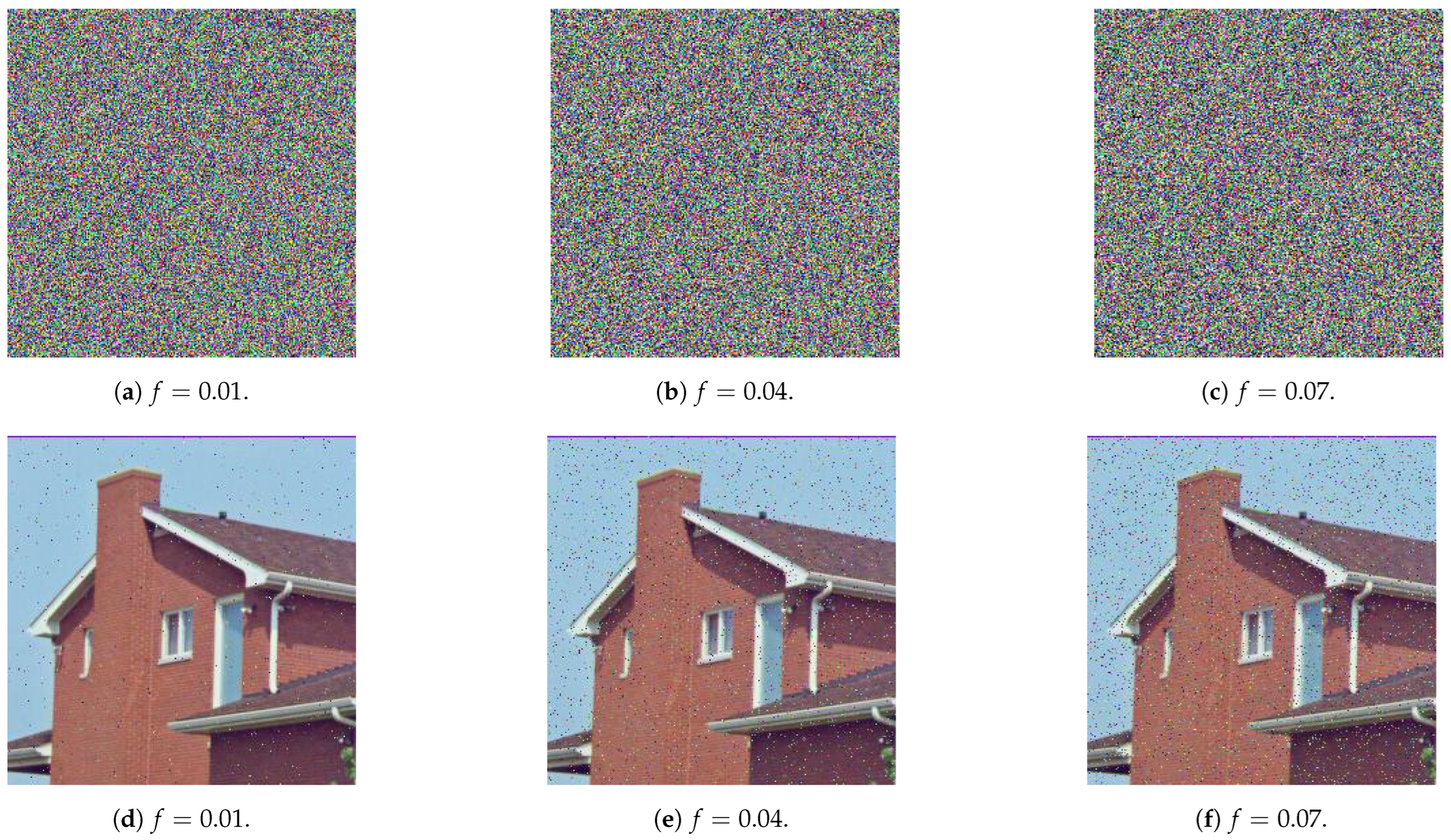
In a noise attack, portions of the pixel values of the encrypted images are altered during transmission owing to channel-deteriorating effects. Figure 21 depicts the effect of a noise attack in which a salt-and-pepper noise is applied to encrypted images resulting from the proposed cryptosystem. When the noisy encrypted images are decrypted, the resulting images seem to retain the visual information of the original image. Thus, the cryptosystem is resistant to salt-and-pepper noise attacks. 
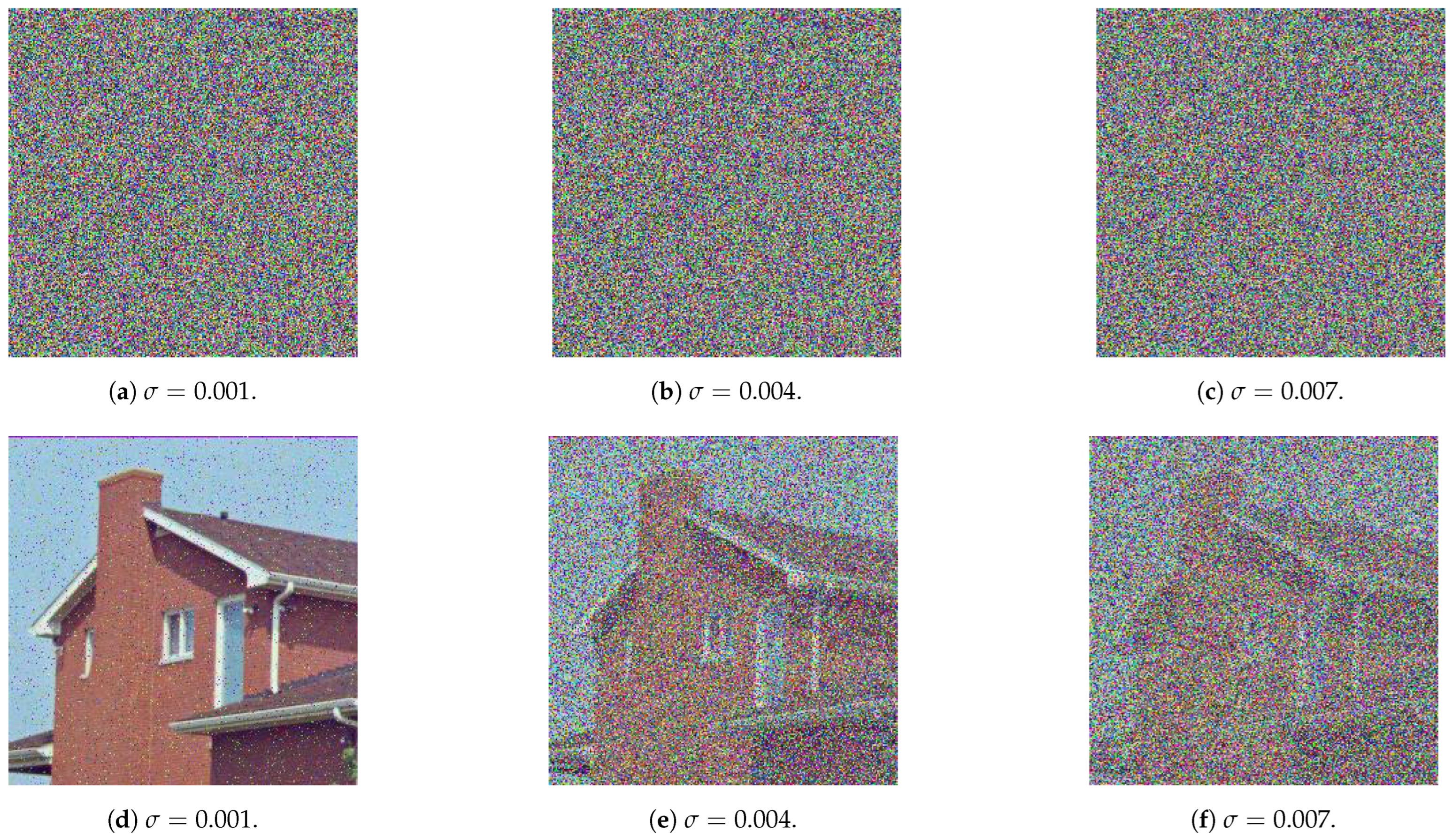
Figure 22 represents the same scenario recreated for the case of a Gaussian noise attack. In both of Figure 21 and Figure 22, it is observed that, for the salt-and-pepper noise attack, with increased fraction of the image, as well as for the Gaussian noise attack, with increased standard deviation, the decrypted image, while still identifiable as the House image, is in worse condition.

5. Conclusions and Future Works

This research work aimed at proposing a novel image cryptosystem that makes use of a multiple-layer-encryption network. For every layer, an encryption key and an S-box were generated and utilized. Design ideas for the encryption keys and S-boxes were pooled from the 4D dynamical Chen system of a fractional-order, the Mersenne Twister, OpenSLL, Rule 30 Cellular Automata and, finally, Intel’s MKL. The employment of the hyperchaotic Chen map and the three PRNGs allowed for the introduction of a large number of variables, which have led to the vast expansion of the key space to 2 1658 . This is indeed one of the differentiating advantages of the proposed image cryptosystem over other state-of-the-art algorithms.
Another such advantage is its superior efficiency, encrypting images at an average rate of 3.34 Mbps. Moreover, the attained security level of the proposed image cryptosystem is shown to be rather high, not only in quantitative terms—as exhibited by the comparable and sometimes superior performance evaluation metrics in relation to the state-of-the-art—but also from a qualitative aspect. Quantitatively, the proposed image cryptosystem showcases the average computed values for some key performance metrics as follows: MSE of 9610.65 , PSNR of 8.33256 dB, MAE of 80.2136 , entropy of 7.99711 , NPCR of 99.6119 % as well as UACI of 31.4563 % .
Qualitatively, upon examining other state-of-the-art algorithms, it is easy to realize that they implement a one-and-a-half layer (i.e., a permutation, a substitution and a final permutation), unlike the proposed image cryptosystem, which implements double that, while maintaining excellent code efficiency. Furthermore, inspection of the encrypted images by the HVS provides no information as to what the original plain image could be. Various cryptanalyses and noise attacks were also shown to be futile in breaking the proposed cryptosystem.
Future research could take on more than one direction. First, while the adopted idea of incorporating the S-box performance evaluation metrics as part of the encryption key itself has much improved the key space, this has inadvertently lead to the utilization of sub-optimal S-boxes. Nevertheless, the performance of the proposed image cryptosystem was not affected by this due to the application of the multiple-layer-encryption network. Still, further improvements could have been attained if better-performing S-boxes been chosen.
Second, some instances in the literature have indicated that, while the Mersenne Twister provides an excellent PRNG performance in general, in strict relation to cryptography applications, other PRNGs could potentially offer improved performance [90]. Once again, this might not have affected the performance of the proposed image cryptosystem due to the application of the multiple-layer-encryption network. In that regard, future works could attempt to replace the Mersenne Twister with other PRNGs of higher cryptographic performance and check for any noticeable overall improvements in the image cryptosystem.

Author Contributions

Conceptualization, W.A. and N.A.; methodology, M.G. and W.A.; software, W.A., N.A. and M.G.; validation, W.A.; writing—original draft preparation, W.A. and M.G.; writing—review and editing, W.A.; visualization, W.A.; supervision, W.A. All authors have read and agreed to the published version of the manuscript.

Funding

This research received no external funding.

Data Availability Statement

Not applicable.

Conflicts of Interest

The authors declare no conflict of interest.

Abbreviations

The following abbreviations are used in this manuscript:
CACellular Automata
DNADeoxyribonucleic Acid
FPGAField Programmable Gate Arrays
HVSHuman Visual System
LFSRLinear Feedback Shift Register
MAEMaximum Absolute Error
MSEMean Square Error
NISTNational Institute of Standards and Technology
NPCRNumber of Pixel Changing Ratio
PRNGPseudo-Random Number Generation
PSNRPeak Signal-to-Noise Ratio
S-boxSubstitution box
UACIUnified Averaged Change Intensity

References

  1. Lu, B.; Dao, P.D.; Liu, J.; He, Y.; Shang, J. Recent advances of hyperspectral imaging technology and applications in agriculture. Remote Sens. 2020, 12, 2659. [Google Scholar] [CrossRef]
  2. Wang, C.; Fan, W.; Zhang, Z.; Wen, Y.; Xiong, L.; Chen, X. Advanced nanotechnology leading the way to multimodal imaging-guided precision surgical therapy. Adv. Mater. 2019, 31, 1904329. [Google Scholar] [CrossRef] [PubMed]
  3. Abd El-Latif, A.A.; Abd-El-Atty, B.; Mazurczyk, W.; Fung, C.; Venegas-Andraca, S.E. Secure data encryption based on quantum walks for 5G Internet of Things scenario. IEEE Trans. Netw. Serv. Manag. 2020, 17, 118–131. [Google Scholar] [CrossRef]
  4. Kagan, D.; Alpert, G.F.; Fire, M. Zooming into video conferencing privacy and security threats. arXiv 2020, arXiv:2007.01059. [Google Scholar]
  5. Gyongyosi, L.; Imre, S. A survey on quantum computing technology. Comput. Sci. Rev. 2019, 31, 51–71. [Google Scholar] [CrossRef]
  6. Elkandoz, M.T.; Alexan, W. Image encryption based on a combination of multiple chaotic maps. Multimed. Tools Appl. 2022, 81, 25497–25518. [Google Scholar] [CrossRef]
  7. Gabr, M.; Alexan, W.; Moussa, K.; Maged, B.; Mezar, A. Multi-Stage RGB Image Encryption. In Proceedings of the 2022 International Telecommunications Conference (ITC-Egypt), Alexandria, Egypt, 26–28 July 2022; pp. 1–6. [Google Scholar]
  8. Gabr, M.; Younis, H.; Ibrahim, M.; Alajmy, S.; Khalid, I.; Azab, E.; Elias, R.; Alexan, W. Application of DNA Coding, the Lorenz Differential Equations and a Variation of the Logistic Map in a Multi-Stage Cryptosystem. Symmetry 2022, 14, 2559. [Google Scholar] [CrossRef]
  9. Gabr, M.; Hussein, H.H.; Alexan, W. A Combination of Decimal-and Bit-Level Secure Multimedia Transmission. In Proceedings of the 2022 Workshop on Microwave Theory and Techniques in Wireless Communications (MTTW), Riga, Latvia, 5–7 October 2022; pp. 177–182. [Google Scholar]
  10. Farrag, S.; Alexan, W. Secure 3d data hiding technique based on a mesh traversal algorithm. Multimed. Tools Appl. 2020, 79, 29289–29303. [Google Scholar] [CrossRef]
  11. Alexan, W.; Elkhateeb, A.; Mamdouh, E.; Al-Seba’Ey, F.; Amr, Z.; Khalil, H. Utilization of corner filters, aes and lsb steganography for secure message transmission. In Proceedings of the 2021 International Conference on Microelectronics (ICM), Nis, Serbia, 12–14 September 2021; pp. 29–33. [Google Scholar]
  12. Alexan, W.; Ashraf, A.; Mamdouh, E.; Mohamed, S.; Moustafa, M. Iomt security: Sha3-512, aes-256, rsa and lsb steganography. In Proceedings of the 2021 Eighth NAFOSTED Conference on Information and Computer Science (NICS), Hanoi, Vietnam, 21–22 December 2021; pp. 177–181. [Google Scholar]
  13. Yasser, S.; Hesham, A.; Hassan, M.; Alexan, W. Aes-secured bit-cycling steganography in sliced 3d images. In Proceedings of the 2020 International Conference on Innovative Trends in Communication and Computer Engineering (ITCE), Cairo, Egypt, 8–9 February 2020; pp. 227–231. [Google Scholar]
  14. Alexan, W.; Mamdouh, E.; ElBeltagy, M.; Hassan, F.; Edward, P. Image Feature-Based Watermarking. In Proceedings of the 2022 International Telecommunications Conference (ITC-Egypt), Alexandria, Egypt, 26–28 July 2022; pp. 1–6. [Google Scholar] [CrossRef]
  15. Coppersmith, D. The Data Encryption Standard (DES) and its strength against attacks. Ibm J. Res. Dev. 1994, 38, 243–250. [Google Scholar] [CrossRef]
  16. Adam, N.; Mashaly, M.; Alexan, W. A 3des double–layer based message security scheme. In Proceedings of the 2019 Second International Conference on Computer Applications & Information Security (ICCAIS), Riyadh, Saudi Arabia, 19–21 March 2019; pp. 1–5. [Google Scholar]
  17. Daemen, J.; Rijmen, V. The Design of Rijndael; Springer: Berlin/Heidelberg, Germany, 2002; Volume 2. [Google Scholar]
  18. Moussa, Y.; Alexan, W. Message security through aes and lsb embedding in edge detected pixels of 3d images. In Proceedings of the 2020 second Novel Intelligent and Leading Emerging Sciences Conference (NILES), Giza, Egypt, 24–26 October 2020; pp. 224–229. [Google Scholar]
  19. Vaudenay, S. An experiment on DES statistical cryptanalysis. In Proceedings of the third ACM Conference on Computer and Communications Security, New Delhi, India, 14–15 March 1996; pp. 139–147. [Google Scholar]
  20. Alexan, W.; ElBeltagy, M.; Aboshousha, A. RGB Image Encryption through Cellular Automata, S-Box and the Lorenz System. Symmetry 2022, 14, 443. [Google Scholar] [CrossRef]
  21. Jiao, K.; Ye, G.; Mei, Q. Image Encryption Scheme Based on Quantum Logistic Map and Cellular Automata. In Proceedings of the 2021 IEEE sixth International Conference on Computer and Communication Systems (ICCCS), Chengdu, China, 23–26 April 2021; pp. 375–379. [Google Scholar] [CrossRef]
  22. Ben Slimane, N.; Aouf, N.; Bouallegue, K.; Machhout, M. Hash Key-Based Image Cryptosystem Using Chaotic Maps and Cellular Automata. In Proceedings of the 2018 15th International Multi-Conference on Systems, Signals Devices (SSD), Yasmine Hammamet, Tunisia, 19–22 March 2018; pp. 190–194. [Google Scholar] [CrossRef]
  23. Vinay, S.; Pujar, A.; Ankith; Kedlaya, H.; Shahapur, V.S. Implementation of DNA cryptography based on dynamic DNA sequence table using cloud computing. Int. J. Eng. Res. Technol. 2019, 7, 8. [Google Scholar]
  24. UbaidurRahman, N.H.; Balamurugan, C.; Mariappan, R. A Novel String Matrix Data Structure for DNA Encoding Algorithm. Procedia Comput. Sci. 2015, 46, 820–832. [Google Scholar] [CrossRef] [Green Version]
  25. Iliyasu, M.A.; Abisoye, O.A.; Bashir, S.A.; Ojeniyi, J.A. A Review of DNA Cryptograhic Approaches. In Proceedings of the 2020 IEEE Second International Conference on Cyberspac (CYBER NIGERIA), Abuja, Nigeria, 23–25 February 2021; pp. 66–72. [Google Scholar]
  26. Sambas, A.; Vaidyanathan, S.; Tlelo-Cuautle, E.; Abd-El-Atty, B.; El-Latif, A.A.A.; Guillén-Fernández, O.; Sukono; Hidayat, Y.; Gundara, G. A 3-D Multi-Stable System with a Peanut-Shaped Equilibrium Curve: Circuit Design, FPGA Realization, and an Application to Image Encryption. IEEE Access 2020, 8, 137116–137132. [Google Scholar] [CrossRef]
  27. Chen, J.J.; Yan, D.W.; Duan, S.K.; Wang, L.D. Memristor-based hyper-chaotic circuit for image encryption. Chin. Phys. 2020, 29, 110504. [Google Scholar] [CrossRef]
  28. Liu, X.; Tong, X.; Wang, Z.; Zhang, M. Efficient high nonlinearity S-box generating algorithm based on third-order nonlinear digital filter. Chaos Solitons Fractals 2021, 150, 111109. [Google Scholar] [CrossRef]
  29. Alexan, W.; ElBeltagy, M.; Aboshousha, A. Image Encryption Through Lucas Sequence, S-Box and Chaos Theory. In Proceedings of the 2021 eighth NAFOSTED Conference on Information and Computer Science (NICS), Hanoi, Vietnam, 21–22 December 2021; pp. 77–83. [Google Scholar]
  30. Khan, M.; Masood, F. A novel chaotic image encryption technique based on multiple discrete dynamical maps. Multimed. Tools Appl. 2019, 78, 26203–26222. [Google Scholar] [CrossRef]
  31. Younas, I.; Khan, M. A new efficient digital image encryption based on inverse left almost semi group and Lorenz chaotic system. Entropy 2018, 20, 913. [Google Scholar] [CrossRef] [Green Version]
  32. Alexan, W.; Elkandoz, M.; Mashaly, M.; Azab, E.; Aboshousha, A. Color Image Encryption Through Chaos and KAA Map. IEEE Access 2023, 11, 11541–11554. [Google Scholar] [CrossRef]
  33. Gabr, M.; Alexan, W.; Moussa, K. Image Encryption Through CA, Chaos and Lucas Sequence Based S-box. In Proceedings of the 2022 Signal Processing: Algorithms, Architectures, Arrangements, and Applications (SPA), Poznan, Poland, 21–22 September 2022; pp. 34–39. [Google Scholar]
  34. ElBeltagy, M.; Alexan, W.; Elkhamry, A.; Moustafa, M.; Hussein, H.H. Image Encryption Through Rössler System, PRNG S-box and Recamán’s Sequence. In Proceedings of the 2022 IEEE 12th Annual Computing and Communication Workshop and Conference (CCWC), Virtual, 26–29 January 2022; pp. 0716–0722. [Google Scholar] [CrossRef]
  35. Hussein, H.H.; Alexan, W.; ElBeltagy, M.; Aboshousha, A. Visual Data Security Incorporating Fibonacci Sequence, S-box, and Chaos Theory. In Proceedings of the 2022 International Conference on Smart Systems and Power Management (IC2SPM), Beirut, Lebanon, 10–12 November 2022; pp. 85–90. [Google Scholar] [CrossRef]
  36. AbdElHaleem, S.H.; Abd-El-Hafiz, S.K.; Radwan, A.G. A generalized framework for elliptic curves based PRNG and its utilization in image encryption. Sci. Rep. 2022, 12, 13278. [Google Scholar] [CrossRef]
  37. Yu, F.; Zhang, Z.; Shen, H.; Huang, Y.; Cai, S.; Du, S. FPGA implementation and image encryption application of a new PRNG based on a memristive Hopfield neural network with a special activation gradient. Chin. Phys. 2022, 31, 020505. [Google Scholar] [CrossRef]
  38. Idrees, B.; Zafar, S.; Rashid, T.; Gao, W. Image encryption algorithm using S-box and dynamic Hénon bit level permutation. Multimed. Tools Appl. 2020, 79, 6135–6162. [Google Scholar] [CrossRef]
  39. Pereira, A.; Proenca, A. PRNG-Broker: A High-Performance Broker to Supply Parallel Streams of Pseudorandom Numbers for Large-Scale Simulations. In Advances in Parallel & Distributed Processing, and Applications: Proceedings from PDPTA’20, CSC’20, MSV’20, and GCC’20, Glasgow, UK, 22–26 August 2021; Springer: Berlin/Heidelberg, Germany, 2021; pp. 167–183. [Google Scholar]
  40. Viega, J.; Messier, M.; Chandra, P. Network Security with openSSL: Cryptography for Secure Communications; O’Reilly Media, Inc.: Sebastopol, CA, USA, 2002. [Google Scholar]
  41. Hosny, K.M. Multimedia Security Using Chaotic Maps: Principles and Methodologies; Springer: Berlin/Heidelberg, Germany, 2020; Volume 884. [Google Scholar]
  42. Kumari, M.; Gupta, S. Performance comparison between Chaos and quantum-chaos based image encryption techniques. Multimed. Tools Appl. 2021, 80, 33213–33255. [Google Scholar] [CrossRef] [PubMed]
  43. Tavazoei, M.S. Fractional order chaotic systems: History, achievements, applications, and future challenges. Eur. Phys. J. Spec. Top. 2020, 229, 887–904. [Google Scholar] [CrossRef]
  44. Montesinos-García, J.J.; Martinez-Guerra, R. Colour image encryption via fractional chaotic state estimation. Iet Image Process. 2018, 12, 1913–1920. [Google Scholar] [CrossRef]
  45. Hosny, K.M.; Kamal, S.T.; Darwish, M.M. Novel encryption for color images using fractional-order hyperchaotic system. J. Ambient. Intell. Humaniz. Comput. 2022, 13, 973–988. [Google Scholar] [CrossRef]
  46. Hou, J.; Xi, R.; Liu, P.; Liu, T. The switching fractional order chaotic system and its application to image encryption. IEEE/CAA J. Autom. Sin. 2016, 4, 381–388. [Google Scholar] [CrossRef]
  47. Bai, Y.R.; Baleanu, D.; Wu, G.C. A novel shuffling technique based on fractional chaotic maps. Optik 2018, 168, 553–562. [Google Scholar] [CrossRef]
  48. Mani, P.; Rajan, R.; Shanmugam, L.; Joo, Y.H. Adaptive control for fractional order induced chaotic fuzzy cellular neural networks and its application to image encryption. Inf. Sci. 2019, 491, 74–89. [Google Scholar] [CrossRef]
  49. Shannon, C.E. Communication theory of secrecy systems. Bell Syst. Tech. J. 1949, 28, 656–715. [Google Scholar] [CrossRef]
  50. Hegazi, A.; Matouk, A. Dynamical behaviors and synchronization in the fractional order hyperchaotic Chen system. Appl. Math. Lett. 2011, 24, 1938–1944. [Google Scholar] [CrossRef] [Green Version]
  51. Yan, Z. Controlling hyperchaos in the new hyperchaotic Chen system. Appl. Math. Comput. 2005, 168, 1239–1250. [Google Scholar] [CrossRef]
  52. Mohamed, S.M.; Sayed, W.S.; Madian, A.H.; Radwan, A.G.; Said, L.A. An Encryption Application and FPGA Realization of a Fractional Memristive Chaotic System. Electronics 2023, 12, 1219. [Google Scholar] [CrossRef]
  53. Matsumoto, M.; Nishimura, T. Mersenne twister: A 623-dimensionally equidistributed uniform pseudo-random number generator. Acm Trans. Model. Comput. Simul. (Tomacs) 1998, 8, 3–30. [Google Scholar] [CrossRef] [Green Version]
  54. L’ecuyer, P.; Simard, R. TestU01: AC library for empirical testing of random number generators. Acm Trans. Math. Softw. (Toms) 2007, 33, 1–40. [Google Scholar] [CrossRef]
  55. Route, M. Radio-flaring ultracool dwarf population synthesis. Astrophys. J. 2017, 845, 66. [Google Scholar] [CrossRef] [Green Version]
  56. Mélard, G. On the accuracy of statistical procedures in Microsoft Excel 2010. Comput. Stat. 2014, 29, 1095–1128. [Google Scholar] [CrossRef] [Green Version]
  57. McEvoy, R.; Curran, J.; Cotter, P.; Murphy, C. Fortuna: Cryptographically secure pseudo-random number generation in software and hardware. In Proceedings of the 2006 IET Irish Signals and Systems Conference, IET, Dublin, Ireland, 10–11 June 2006; pp. 457–462. [Google Scholar]
  58. Bello, L. DSA-1571-1 Openssl–Predictable Random Number Generator; Debian Security Advisory: Albany, NY, USA, 2008. [Google Scholar]
  59. Wang, E.; Zhang, Q.; Shen, B.; Zhang, G.; Lu, X.; Wu, Q.; Wang, Y.; Wang, E.; Zhang, Q.; Shen, B.; et al. Intel Math Kernel Library. In High-Performance Computing on the Intel® Xeon Phi™: How to Fully Exploit MIC Architectures; Springer: Berlin/Heidelberg, Germany, 2014; pp. 167–188. [Google Scholar]
  60. Iqbal, N.; Naqvi, R.A.; Atif, M.; Khan, M.A.; Hanif, M.; Abbas, S.; Hussain, D. On the Image Encryption Algorithm Based on the Chaotic System, DNA Encoding, and Castle. IEEE Access 2021, 9, 118253–118270. [Google Scholar] [CrossRef]
  61. Khan, M.; Shah, T. An efficient chaotic image encryption scheme. Neural Comput. Appl. 2015, 26, 1137–1148. [Google Scholar] [CrossRef]
  62. Liu, H.; Zhao, B.; Huang, L. Quantum image encryption scheme using Arnold transform and S-box scrambling. Entropy 2019, 21, 343. [Google Scholar] [CrossRef] [Green Version]
  63. Wang, Y.; Wu, C.; Kang, S.; Wang, Q.; Mikulovich, V. Multi-channel chaotic encryption algorithm for color image based on DNA coding. Multimed. Tools Appl. 2020, 79, 18317–18342. [Google Scholar] [CrossRef]
  64. Zhang, Y.Q.; He, Y.; Li, P.; Wang, X.Y. A new color image encryption scheme based on 2DNLCML system and genetic operations. Opt. Lasers Eng. 2020, 128, 106040. [Google Scholar] [CrossRef]
  65. Jithin, K.; Sankar, S. Colour image encryption algorithm combining, Arnold map, DNA sequence operation, and a Mandelbrot set. J. Inf. Secur. Appl. 2020, 50, 102428. [Google Scholar] [CrossRef]
  66. Rehman, A.U.; Firdous, A.; Iqbal, S.; Abbas, Z.; Shahid, M.M.A.; Wang, H.; Ullah, F. A Color Image Encryption Algorithm Based on One Time Key, Chaos Theory, and Concept of Rotor Machine. IEEE Access 2020, 8, 172275–172295. [Google Scholar] [CrossRef]
  67. Slimane, N.B.; Aouf, N.; Bouallegue, K.; Machhout, M. A novel chaotic image cryptosystem based on DNA sequence operations and single neuron model. Multimed. Tools Appl. 2018, 77, 30993–31019. [Google Scholar] [CrossRef]
  68. Paul, L.; Gracias, C.; Desai, A.; Thanikaiselvan, V.; Suba Shanthini, S.; Rengarajan, A. A novel colour image encryption scheme using dynamic DNA coding, chaotic maps, and SHA-2. Multimed. Tools Appl. 2022, 81, 37873–37894. [Google Scholar] [CrossRef]
  69. Stine, K.; Kissel, R.; Barker, W.; Lee, A.; Fahlsing, J. Guide for Mapping Types of Information and Information Systems to Security Categories: Appendices; Technical Report; National Institute of Standards and Technology: Gaithersburg, MD, USA, 2008. [Google Scholar]
  70. ur Rehman, A.; Liao, X.; Ashraf, R.; Ullah, S.; Wang, H. A color image encryption technique using exclusive-OR with DNA complementary rules based on chaos theory and SHA-2. Optik 2018, 159, 348–367. [Google Scholar] [CrossRef]
  71. Alvarez, G.; Li, S. Some basic cryptographic requirements for chaos-based cryptosystems. Int. J. Bifurc. Chaos 2006, 16, 2129–2151. [Google Scholar] [CrossRef] [Green Version]
  72. Yang, B.; Liao, X. A new color image encryption scheme based on logistic map over the finite field ZN. Multimed. Tools Appl. 2018, 77, 21803–21821. [Google Scholar] [CrossRef]
  73. Gao, H.; Wang, X. Chaotic Image Encryption Algorithm Based on Zigzag Transform With Bidirectional Crossover From Random Position. IEEE Access 2021, 9, 105627–105640. [Google Scholar] [CrossRef]
  74. Ge, B.; Chen, X.; Chen, G.; Shen, Z. Secure and Fast Image Encryption Algorithm Using Hyper-Chaos-Based Key Generator and Vector Operation. IEEE Access 2021, 9, 137635–137654. [Google Scholar] [CrossRef]
  75. Hu, X.; Wei, L.; Chen, W.; Chen, Q.; Guo, Y. Color image encryption algorithm based on dynamic chaos and matrix convolution. IEEE Access 2020, 8, 12452–12466. [Google Scholar] [CrossRef]
  76. Asuero, A.G.; Sayago, A.; González, A. The correlation coefficient: An overview. Crit. Rev. Anal. Chem 2006, 36, 41–59. [Google Scholar] [CrossRef]
  77. Temizhan, E.; Mirtagioglu, H.; Mendes, M. Which Correlation Coefficient Should Be Used for Investigating Relations between Quantitative Variables? Am. Acad. Sci. Res. J. Eng. Technol. Sci. 2022, 85, 265–277. [Google Scholar]
  78. Gong, L.; Qiu, K.; Deng, C.; Zhou, N. An image compression and encryption algorithm based on chaotic system and compressive sensing. Opt. Laser Technol. 2019, 115, 257–267. [Google Scholar] [CrossRef]
  79. Zhang, X.; Wang, L.; Wang, Y.; Niu, Y.; Li, Y. An image encryption algorithm based on hyperchaotic system and variable-step Josephus problem. Int. J. Opt. 2020, 2020, 6102824. [Google Scholar] [CrossRef]
  80. Meier, W.; Staffelbach, O. Nonlinearity criteria for cryptographic functions. In Proceedings of the Workshop on the Theory and Application of of Cryptographic Techniques, Houthalen, Belgium, 10–13 April 1989; pp. 549–562. [Google Scholar]
  81. Hong, S.; Lee, S.; Lim, J.; Sung, J.; Cheon, D.; Cho, I. Provable security against differential and linear cryptanalysis for the SPN structure. In Proceedings of the International Workshop on Fast Software Encryption, New York, NY, USA, 10–12 April 2000; pp. 273–283. [Google Scholar]
  82. Biham, E.; Shamir, A. Differential cryptanalysis of DES-like cryptosystems. J. Cryptol. 1991, 4, 3–72. [Google Scholar] [CrossRef]
  83. Webster, A.; Tavares, S.E. On the design of S-boxes. In Proceedings of the Conference on the Theory and Application of Cryptographic Techniques, Aarhus, Denmark, 21–24 May 1985; pp. 523–534. [Google Scholar]
  84. Liu, H.; Kadir, A.; Xu, C. Cryptanalysis and constructing S-box based on chaotic map and backtracking. Appl. Math. Comput. 2020, 376, 125153. [Google Scholar] [CrossRef]
  85. Si, Y.; Liu, H.; Chen, Y. Constructing keyed strong S-Box using an enhanced quadratic map. Int. J. Bifurc. Chaos 2021, 31, 2150146. [Google Scholar] [CrossRef]
  86. Zahid, A.H.; Arshad, M.J.; Ahmad, M. A novel construction of efficient substitution-boxes using cubic fractional transformation. Entropy 2019, 21, 245. [Google Scholar] [CrossRef] [Green Version]
  87. Aboytes-González, J.; Murguía, J.; Mejía-Carlos, M.; González-Aguilar, H.; Ramírez-Torres, M. Design of a strong S-box based on a matrix approach. Nonlinear Dyn. 2018, 94, 2003–2012. [Google Scholar] [CrossRef]
  88. Hayat, U.; Azam, N.A.; Asif, M. A method of generating 8 × 8 substitution boxes based on elliptic curves. Wirel. Pers. Commun. 2018, 101, 439–451. [Google Scholar] [CrossRef]
  89. Siddiqui, N.; Yousaf, F.; Murtaza, F.; Ehatisham-ul Haq, M.; Ashraf, M.U.; Alghamdi, A.M.; Alfakeeh, A.S. A highly nonlinear substitution-box (S-box) design using action of modular group on a projective line over a finite field. PLoS ONE 2020, 15, e0241890. [Google Scholar] [CrossRef] [PubMed]
  90. O’Neill, M.E. PCG: A Family of Simple Fast Space-Efficient Statistically Good Algorithms for Random Number Generation; Technical Report HMC-CS-2014-0905; Harvey Mudd College: Claremont, CA, USA, 2014. [Google Scholar]
Figure 1. 3D plots utilizing various axes for the fractional order 4D Chen system. The values used are { x , y , z , u } = 0.3 , a = 35 , b = 3 , c = 12 , γ = 28 , d = 0.5 and α = 0.97 (since the system is calculated in the 4D space, initial values are needed for the four axes. However, for visualization purposes, a single axis is ignored in each plot). The color models the time factor representing initiations with cold colors and ending with hot colors.
Fractalfract 07 00287 g001
Figure 2. Bifurcation plots of the fractional order 4D Chen system for x , y , z and u against b.
Fractalfract 07 00287 g002
Figure 3. Bifurcation plots of the fractional order 4D Chen system for x , y , z and u against c.
Fractalfract 07 00287 g003
Figure 4. A plot of the 4 Lyapunov characteristic exponents of the fractional order 4D Chen system.
Fractalfract 07 00287 g004
Figure 5. Rule 30 CA: The present state and next state for the center cell.
Fractalfract 07 00287 g005
Figure 6. Rule 30 CA: A plot of the first 10 steps.
Fractalfract 07 00287 g006
Figure 7. Rule 30 CA: A plot of the first 100 steps.
Fractalfract 07 00287 g007
Figure 8. Flow chart of the encryption process of the proposed image cryptosystem.
Fractalfract 07 00287 g008
Figure 9. Flow chart of the decryption process of the proposed image cryptosystem.
Fractalfract 07 00287 g009
Figure 10. Mandrill image and histogram comparison pre- and post-encryption.
Fractalfract 07 00287 g010
Figure 11. Sailboat image and histogram comparison pre- and post-encryption.
Fractalfract 07 00287 g011
Figure 12. Peppers image and histogram comparison pre- and post-encryption.
Fractalfract 07 00287 g012
Figure 13. House image and histogram comparison pre- and post-encryption.
Fractalfract 07 00287 g013
Figure 14. House2 image and histogram comparison pre- and post-encryption.
Fractalfract 07 00287 g014
Figure 15. Tree image as well as its Fourier transformation and 3D plots of its co-occurrence matrix pre- and post-encryption.
Fractalfract 07 00287 g015
Figure 16. 2D plot of co-occurrence matrices of the Tree image pre- and post-encryption.
Fractalfract 07 00287 g016
Figure 17. 2D plot of co-occurrence matrices of the red channel of the Tree image pre- and postencryption.
Fractalfract 07 00287 g017
Figure 18. 2D plot of co-occurrence matrices of the green channel of the Tree image pre- and postencryption.
Fractalfract 07 00287 g018
Figure 19. 2D plot of co-occurrence matrices of the blue channel of the Tree image pre- and postencryption.
Fractalfract 07 00287 g019
Figure 20. Various occlusion attacks on encrypted images (ac) and their corresponding decrypted versions (df).
Fractalfract 07 00287 g020
Figure 21. Various salt-and-pepper noise attacks to a fraction f of the encrypted images (ac) and their corresponding decrypted versions (df).
Fractalfract 07 00287 g021
Figure 22. Various zero-mean Gaussian noise attacks with standard deviation σ on the encrypted images (ac) and their corresponding decrypted versions (df).
Fractalfract 07 00287 g022
Table 1. Proposed Mersenne-Twister-based S-box.
49020915217835921024020418197187165116131
25214644144180130223402423476322012115046
3313783158274124823711918109222784170160
2514822216321111317216662961182073731107224
10217922674112254205218512260122001648123
13230190127346516918354129170236136245186
8515132239582251231202211851259512415419588
20214323282191731451402081017939247135194250
202162623387715522241126238592445212130
4902144221018219638531714523582231242104
71561688077191111177610057155117161217189
10368203148662284399229911341051281493192
157162138294732121155010621325324663151176
75110147619159722519394165116736206198
139174188133220108171121573642551418969142
67781755618424928199886199243149114197153
Table 2. Proposed OpenSSL-based S-box.
7320216124342524016516836742531692123834
8292326611110221071195247321648258196151
62591661122444919324124020039912284847137
220204501461782453010011722135107206194149182
165288122205109224676818615817280860144
1186572199941082519150994527159104185249
246631718821295218561529620944132897611
175113174571282342679611902981422076914
123375318873112414723184198314513385106
120198462391771552302354320120782813516323
312512712113911625417113777140176170250119
208131252251151537510121923721721610187215189
925538191248143192227197419770541411224
53323681221545113023364602031031514890
181157613812913412622911424218416042226183222
105111021318022393136179255156167211162214173
Table 3. Proposed Intel’s MKL-based S-box.
13792022341252324121925077132479944208230
10091238149213117561351851063174782274361
17811918310481195218672322484819311513328
8415520617217519218736235200136199191170247
55180130834564159215392402115810262224232
2141225165904620121714516211621214150189143
16619812817774842210322623320910513129150154
1842371561762281471535314289202638148169182
67239351461941652107197761072201711581127
411012442258819011311020422911211116198252164
162361952412010611420568961631381291415718
231302421522439517375341212212451882216
66123181109167314954617751179249118108
255301533607313979168932238287169197
21814025354292207124196578520312715116025
212222461268613414480374094135970122254
Table 4. Comparison of MSE values with the literature.
ImageProposed[8][29][30][31][20][60]
Lena 8912.4 9112.1 8926.96 10,869.73 4859.03 8888.88 N/A
Mandrill 8320.41 8573.38 8290.84 10,930.33 6399.05 8295.21 N/A
Peppers10,065.410,298.710,045.1N/A 7274.44 10,092.3N/A
House 8395.53 8427.04 8351.64 N/AN/AN/AN/A
House2 9142.54 9374.65 N/AN/AN/AN/AN/A
Girl12,104.212,450.9N/AN/AN/AN/AN/A
Sailboat10,071.9N/AN/AN/AN/AN/AN/A
Tree 9873.24 N/AN/AN/AN/AN/AN/A
Average 9610.65 9706.13 8903.64 10 , 900 61 , 77.51 9092.13 N/A
Table 5. Comparison of PSNR values, in dB, with the literature.
ImageProposed[8][29][30][31][20][60]
Lena 8.63086 8.53462 8.6237 7.7677 11.3 8.64233 8.5674
Mandrill 8.92936 8.79929 8.9448 7.7447 10.10 8.94253 10.0322
Peppers 8.10248 8.00296 8.11128 N/A 9.55 N/AN/A
House 8.89032 8.87405 8.91309 N/AN/AN/AN/A
House2 8.52013 8.41125 N/AN/AN/AN/AN/A
Girl 7.30144 7.17879 N/AN/AN/AN/AN/A
Sailboat 8.0997 N/AN/AN/AN/AN/AN/A
Tree 8.18621 N/AN/AN/AN/AN/AN/A
Average 8.33256 8.30016 8.64822 7.7562 10.3167 8.79243 9.2998
Table 6. Comparison of MAE values with the literature.
ImageProposed[8][20][30][61][60]
Lena 77.4877 78.3564 77.3752 87 77.35 77.96
Peppers 81.9832 82.3273 81.7740 N/A 74.71 N/A
Mandrill 75.1632 81.913 75.1659 92 73.91 67.85
House 75.4983 N/AN/AN/AN/AN/A
House 2 78.3327 N/AN/AN/AN/AN/A
Girl 89.9807 N/AN/AN/AN/AN/A
Sailboat 82.1003 N/AN/AN/AN/AN/A
Tree 81.1623 N/AN/AN/AN/AN/A
Average 80.2136 80.8656 78.105 89.5 75.3233 72.905
Table 7. Comparison of information entropy values with the literature.
ImageProposed[8][29][30][62][31][20][60]
Lena 7.99887 7.9856 7.999 7.999 7.997 7.996 7.997 7.9972
Mandrill 7.99866 7.9905 7.999 7.999 7.999 N/A 7.996 7.9969
Peppers 7.99834 7.9951 7.999 7.9991 N/A 7.997 7.9969 N/A
House 7.99729 7.9577 7.999 N/AN/AN/AN/AN/A
House2 7.99848 7.9847 N/AN/AN/AN/AN/AN/A
Girl 7.99477 7.9789 N/AN/AN/AN/AN/AN/A
Sailboat 7.99875 N/AN/AN/AN/AN/AN/AN/A
Tree 7.99713 N/AN/AN/AN/AN/AN/AN/A
Average 7.99711 7.98208 7.999 7.999 7.99903 7.9965 7.99663 7.99705
Table 8. Correlation coefficients of plain and encrypted images.
Plain ImageEncrypted Image
Correlation CoefficientCorrelation Coefficient
ImageHorizontalDiagonalVerticalHorizontalDiagonalVertical
Lena 0.938611 0.913175 0.96833 0.0064113 0.0015143 0.000568333
Peppers 0.959422 0.930426 0.966795 0.00834328 0.00327485 0.00222402
Mandrill 0.848778 0.750624 0.79088 0.00007897 0.00157688 0.00200228
Table 9. Comparison with the literature of the correlation coefficient values for plain and encrypted versions of the Lena image.
SchemeHorizontalDiagonalVertical
Proposed 0.0064113 0.0015143 0.000568333
[8] 0.003265 0.00413 0.002451
[30] 0.0054 0.0054 0.0016
[20] 0.002287 0.00132 0.00160
[60] 0.0061 0.0018 0.0067
[63] 0.000199 0.003705 0.000924
Table 10. Comparison with the literature of the correlation coefficient values in three directions for plain and encrypted versions of the Lena image computed for each color channel separately.
ChannelDirectionPlain ImageEncrypted Image[64][65][66][20]
RedHorizontal 0.952474 0.00771152 0.001365 0.0021 0.9568 0.00364
Diagonal 0.928029 0.003263 0.000232 0.0026 0.0075 0.00016
Vertical 0.975913 0.00199022 0.004776 0.0018 0.0376 0.000697
GreenHorizontal 0.935628 0.000053 0.003294 0.0006 0.0020 0.000118
Diagonal 0.910534 0.0026447 0.004807 0.0001 0.0046 0.00177
Vertical 0.966647 0.003507 0.000579 0.0004 0.0013 0.0011
BlueHorizontal 0.917439 0.000962 0.002060 0.005 0.0071 0.00164
Diagonal 0.888482 0.004093 0.004043 0.0104 0.0009 0.00523
Vertical 0.947961 0.00259674 0.000194 0.001 0.0423 0.006041
Table 11. NPCR and UACI of various images.
MetricImageResult
NPCRLena 99.5855
Peppers 99.6435
Mandrill 99.6023
House 99.5972
House2 99.6241
Girl 99.6546
Sailboat 99.6048
Tree 99.5829
Average 99.6119
UACILena 30.3873
Peppers 32.1503
Mandrill 29.4757
House 29.607 2
House2 30.7187
Girl 35.2865
Sailboat 32.1962
Tree 31.8284
Average 31.4563
Table 12. Comparison of the NPCR and UACI values computed for various images’ color channels.
MetricImageColor ChannelProposed[20][67]
NPCRLenaRed 99.5712 99.6109 99.6355
Green 99.5758 99.6109 99.6256
Blue 99.6094 99.6375 99.6159
PeppersRed 99.6338 99.6032 99.6307
Green 99.6338 99.6032 99.6250
Blue 99.6628 99.3750 99.6213
MandrillRed 99.5911 99.5880 99.6102
Green 99.5865 99.5880 99.6134
Blue 99.6292 99.5880 99.6057
UACILenaRed 33.1056 33.4158 33.4657
Green 30.5178 30.3902 33.4552
Blue 27.5385 33.2420 33.4550
PeppersRed 28.8353 33.3459 33.4832
Green 33.8409 33.4702 33.4904
Blue 33.7746 33.4357 33.4619
MandrillRed 29.5137 33.4273 33.5002
Green 28.0464 33.4635 33.4711
Blue 30.8671 33.7951 33.4951
Table 13. Comparison of NPCR and UACI values of the Lena image.
SchemeNPCRUACI
Proposed99.585530.3873
[30] 99.52 26.793
[20] 99.63 30.3432
[32] 99.625 30.5681
[60] 99.61 33.516
[68] 99.63 33.48
Table 14. NIST analysis on the encrypted Lena image.
Test NameValueRemarks
Frequency 0.677248 Success
Block Frequency 0.478516 Success
Run 0.667837 Success
Longest run of ones 0.136182 Success
Rank 0.743617 Success
Spectral FFT 0.522490 Success
Non overlapping 0.202310 Success
Overlapping 0.590476 Success
Universal 0.775967 Success
Linear complexity 0.688046 Success
Serial 0.950997 Success
Approximate Entropy 0.094460 Success
Cumulative sum (forward) 0.704199 Success
Cumulative sum (reverse) 0.363251 Success
Table 15. A comparison of key-space values.
AlgorithmKey Space
Proposed 10 496 2 1658
[8] 2 372
[32] 2 478
[60] 2 604
[63] 2 187
[70] 2 312
[72] 2 256
[73] 2 256
[74] 2 345
[75] 2 219
Table 16. Histogram dependency tests for various images.
ImageColor β (31) γ (32) τ (33) ρ (34)r (35)
LenaRed 0.110694 0.0347993 0.0337626 0.0481434 0.0132834
Green 0.0158119 0.0215872 0.0213466 0.0354592 0.0373801
Blue 0.0514905 0.0646801 0.0608846 0.0878873 0.0543499
Combined 0.015625 0.0276274 0.0274928 0.0420548 0.0527299
PeppersRed 0.0553381 0.0327303 0.0320445 0.0441645 0.0552461
Green 0.00793776 0.00618093 0.0061233 0.00892123 0.0309788
Blue 0.0316267 0.0302744 0.0298716 0.047874 0.0160251
Combined 0.0472456 0.0437633 0.0435566 0.0676501 0.0410837
MandrillRed 0.0198853 0.0565044 0.0558669 0.0816251 0.0595621
Green 0.046875 0.00948634 0.00932192 0.0154712 0.0016778
Blue 0.0825168 0.0616492 0.0611381 0.0939456 0.0924138
Combined 0.046875 0.0745872 0.0742411 0.110141 0.0934929
HouseRed 0.110243 0.0104633 0.0102083 0.0137227 0.129594
Green 0.0156864 0.0230578 0.0228953 0.0316539 0.127908
Blue 0.0433977 0.0520028 0.0499645 0.0761799 0.0458134
Combined 0.03125 0.0195387 0.0194504 0.0282111 0.0149416
House2Red 0.0594233 0.00223601 0.00220542 0.00585658 0.0241044
Green 0.0828449 0.00492304 0.00488175 0.00884184 0.0531022
Blue 0.0079207 0.0105576 0.0103937 0.0162964 0.00611405
Combined 0.043395 0.0143268 0.0142559 0.0229318 0.0314425
GirlRed 0.0866627 0.0242129 0.0204944 0.025068 0.0205761
Green 0.0474911 0.0689793 0.0573322 0.077706 0.104362
Blue 0.030644 0.054669 0.0443616 0.0605645 0.0420095
Combined 0.03125 0.0340795 0.0326326 0.0450366 0.0657316
SailboatRed 0.0158114 0.00693224 0.00666217 0.0118382 0.0119124
Green 0.039685 0.0265376 0.0262888 0.0422393 0.0116989
Blue 0.0714466 0.040201 0.0397032 0.0554966 0.00863334
Combined 0.0435716 0.054667 0.0544031 0.0806747 0.0740552
TreeRed 0.0960611 0.034327 0.0336832 0.0463177 0.00928989
Green 0.0591786 0.0368575 0.036362 0.0540911 0.0376557
Blue 0.046875 0.045737 0.0441452 0.0640862 0.019782
Combined0 0.0226485 0.022537 0.034886 0.0006252
Table 17. Processing times of the proposed image cryptosystem for the House image at various dimensions.
Image Dimensions t Enc [s] t Dec [s] t Add [s]
64 × 64 0.028884 0.026181 0.055065
128 × 128 0.107976 0.116058 0.232116
256 × 256 0.426243 0.463615 0.889858
512 × 512 1.88184 1.64237 3.52422
1024 × 1024 7.66508 6.70321 15.3302
Table 18. A comparison of the encryption time for various state-of-the-art algorithms for the Lena image with dimensions 256 × 256 .
Algorithm t Enc [s]Machine Specifications (CPU and RAM)
Proposed 0.426243 2.9 GHz Intel® CoreTM i9, 32 GB
[8] 1.42545 2.9 GHz Intel® CoreTM i9, 32 GB
[20] 2.582389 2.9 GHz Intel® CoreTM i9, 32 GB
[32] 2.750966 3.4 GHz Intel®
[60] 2.7236 2.7 GHz Intel® CoreTM i7, 8 GB
[75] 3.45 N/A
[78] 1.1168 3.4 GHz Intel® CoreTM i7, 8 GB
[79] 1.112 3.4 GHz Intel® CoreTM i3, 4 GB
Table 21. Description of various types of attacks.
AttackNeeded Information by Cryptanalyst
Ciphertext only
1.
Cryptosystem
2.
Encrypted image to be decoded
Known plaintext
1.
Cryptosystem
2.
Encrypted image to be decoded
3.
Plain image and corresponding encrypted image with the encryption key
Chosen ciphertext
1.
Cryptosystem
2.
Encrypted image to be decoded
3.
Reported encrypted image chosen by cryptanalyst alongside its corresponding plain image generated with the cryptosystem and decryption key
Chosen plaintext
1.
Cryptosystem
2.
Encrypted image to be decoded
3.
Reported plain image chosen by cryptanalyst alongside its corresponding encrypted image generated with the cryptosystem and encryption key
Disclaimer/Publisher’s Note: The statements, opinions and data contained in all publications are solely those of the individual author(s) and contributor(s) and not of MDPI and/or the editor(s). MDPI and/or the editor(s) disclaim responsibility for any injury to people or property resulting from any ideas, methods, instructions or products referred to in the content.

