
Seismic Isolation Materials for Bored Rock Tunnels: A Parametric Analysis

Abstract
:1. Introduction
2. Rock Tunneling
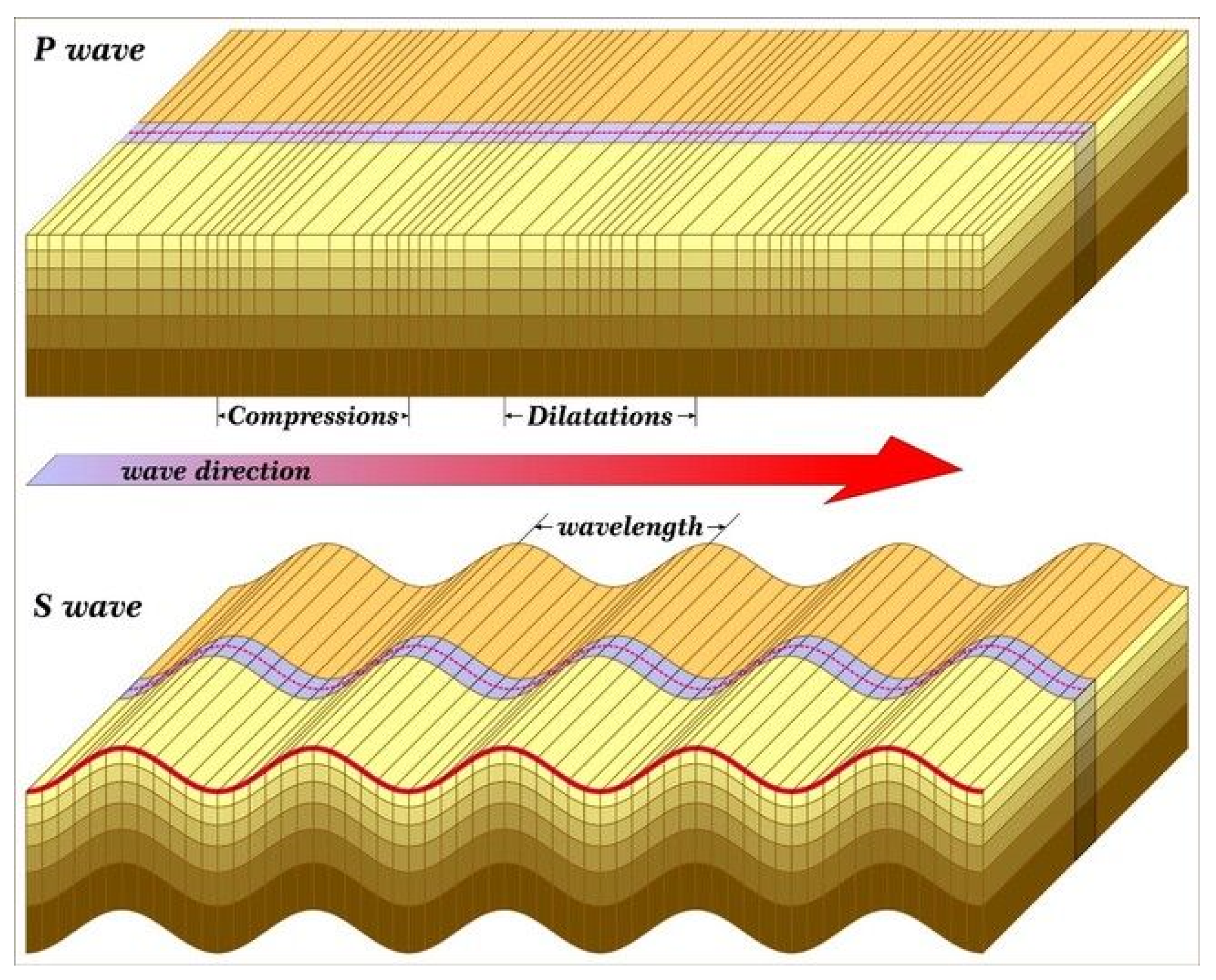
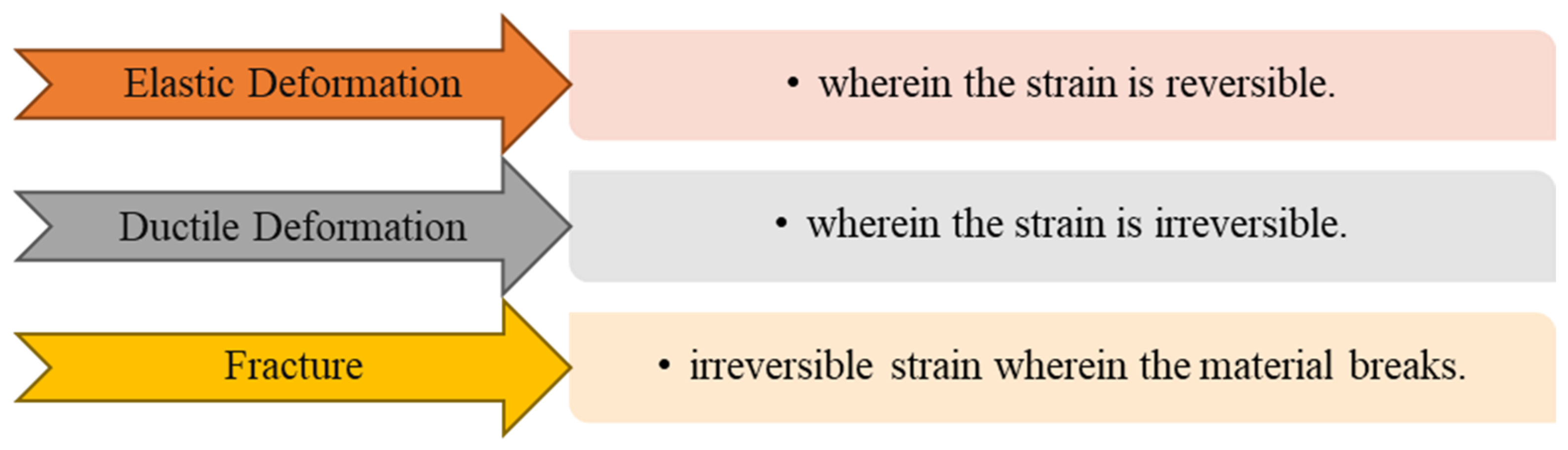
2.1. Seismic Response of Rock
2.2. Seismic Isolation of Rock Tunneling
3. Numerical Modeling
Model Establishment
4. Results
5. Discussion
6. Conclusions
Author Contributions
Funding
Data Availability Statement
Conflicts of Interest
References
- Huo, H.; Bobet, A.; Fernández, G.; Ramírez, J. Load transfer mechanisms between underground structure and surrounding ground: Evaluation of the failure of the Daikai station. J. Geotech. Geoenvironment. Eng. 2005, 131, 1522–1533. [Google Scholar] [CrossRef]
- Li, T. Damage to mountain tunnels related to the Wenchuan earthquake and some suggestions for aseismic tunnel construction. Bull. Eng. Geol. Environ. 2012, 71, 297–308. [Google Scholar] [CrossRef]
- Wang, W.L.; Wang, T.T.; Su, J.J.; Lin, C.H.; Seng, C.R.; Huang, T.H. Assessment of damage in mountain tunnels due to the Taiwan Chi-Chi Earthquake. Tunn. Undergr. Space Technol. 2001, 16, 133–150. [Google Scholar] [CrossRef]
- Wang, H.; Cui, S.; Pei, X.; Zhu, L.; Yang, Q.; Huang, R. Geology amplification of the seismic response of a large deep-seated rock slope revealed by field monitoring and geophysical methods. Environ. Earth Sci. 2022, 81, 191. [Google Scholar] [CrossRef]
- Zhang, Z.; Zhang, Q.; Duan, K.; Ren, M.; Yin, X.; Lin, H.; Xiang, W. Experimental study on the mechanical and permeability behaviors of limestone under hydro-mechanical-coupled conditions. Bull. Eng. Geol. Environ. 2021, 80, 2859–2873. [Google Scholar] [CrossRef]
- Cui, S.; Pei, X.; Jiang, Y.; Wang, G.; Fan, X.; Yang, Q.; Huang, R. Liquefaction within a bedding fault: Understanding the initiation and movement of the Daguangbao landslide triggered by the 2008 Wenchuan Earthquake (Ms = 8.0). Eng. Geol. 2012, 295, 106455. [Google Scholar] [CrossRef]
- Gao, Y.; Xu, F.; Zhang, Q.; He, P.; Qin, Z. Geotechnical monitoring and analyses on the stability and health of a large cross-section railway tunnel constructed in a seismic area. Measurement 2018, 122, 620–629. [Google Scholar] [CrossRef]
- Kontoe, S.; Zdravkovic, L.; Potts, D.M.; Menkiti, C.O. Case study on seismic tunnel response. Can. Geotech. J. 2008, 45, 1743–1764. [Google Scholar] [CrossRef]
- Wang, Z.Z.; Jiang, Y.J.; Zhu, C.A.; Sun, T.C. Shaking table tests of tunnel linings in progressive states of damage. Tunn. Undergr. Space Technol. 2015, 50, 109–117. [Google Scholar] [CrossRef]
- He, J.; Chen, W.; Zhao, W.; Huang, S.; Yao, Y. Numerical test on polystyrene tunnel seismic-isolation material. Pol. J. Chem. Technol. 2016, 18, 122–127. [Google Scholar] [CrossRef]
- Xu, H.; Li, T.; Xia, L.; Zhao, J.X.; Wang, D. Shaking table tests on seismic measures of a model mountain tunnel. Tunn. Undergr. Space Technol. 2016, 60, 197–209. [Google Scholar] [CrossRef]
- Liu, X.; Zhuang, Y.; Zhou, X.; Li, C.; Lin, B.; Liang, N.; Zhong, Z.; Deng, Z. Numerical study of the mechanical process of long-distance replacement of the definitive lining in severely damaged highway tunnels. Undergr. Space 2023, 9, 200–217. [Google Scholar] [CrossRef]
- Wang, Z.Z.; Zhang, Z. Seismic damage classification and risk assessment of mountain tunnels with a validation for the 2008 Wenchuan earthquake. Soil Dyn. Earthq. Eng. 2013, 45, 45–55. [Google Scholar] [CrossRef]
- Zhang, X.; Jiang, Y.; Sugimoto, S. Seismic damage assessment of mountain tunnel: A case study on the Tawarayama tunnel due to the 2016 Kumamoto Earthquake. Tunn. Undergr. Space Technol. 2018, 71, 138–148. [Google Scholar] [CrossRef]
- Wang, Z.Z.; Jiang, Y.J.; Zhu, C.A. Seismic energy response and damage evolution of tunnel lining structures. Eur. J. Environ. Civ. Eng. 2019, 23, 758–770. [Google Scholar] [CrossRef]
- Power, M.; Rosidi, D.; Kaneshiro, J.; Gilstrap, S.; Chiou, S.J. Summary and Evaluation of Procedures for the Seismic Design of Tunnels. Final Report for Task 112-d-5.3 (c); National Center for Earthquake Engineering Research: Buffalo, NY, USA, 1998. [Google Scholar]
- Konagai, K.; Kim, D.S. Simple evaluation of the effect of seismic isolation by covering a tunnel with a thin flexible material. Soil Dyn. Earthq. Eng. 2001, 21, 287–295. [Google Scholar] [CrossRef]
- Kim, K. Konagai, Seismic isolation effect of a tunnel covered with coating material. Tunn. Undergr. Space Technol. 2000, 15, 437–443. [Google Scholar] [CrossRef]
- Shi, Z.; Cheng, Z.; Xiang, H. Seismic isolation foundations with effective attenuation zones. Soil Dyn. Earthq. Eng. 2014, 57, 143–151. [Google Scholar] [CrossRef]
- Lanzano, G.; Bilotta, E.; Russo, G.; Silvestri, F. Experimental and numerical study on circular tunnels under seismic loading. Eur. J. Environ. Civ. Eng. 2015, 19, 539–563. [Google Scholar] [CrossRef]
- Owen, G.N.; Scholl, R.E. Earthquake Engineering of Large Underground Structures. Available online: https://rosap.ntl.bts.gov/view/dot/30095 (accessed on 31 December 2023).
- Chen, Z.Y.; Shen, H. Dynamic centrifuge tests on isolation mechanism of tunnels subjected to seismic shaking. Tunn. Undergr. Space Technol. 2014, 42, 67–77. [Google Scholar] [CrossRef]
- Chen, Z.; Liang, S.; Shen, H.; He, C. Dynamic centrifuge tests on effects of isolation layer and cross-section dimensions on shield tunnels. Soil Dyn. Earthq. Eng. 2018, 109, 173–187. [Google Scholar] [CrossRef]
- Penzien, J.; Wu, C.L. Stresses in linings of bored tunnels. Earthq. Eng. Struct. Dyn. 1998, 27, 283–300. [Google Scholar] [CrossRef]
- Cilingir, U.; Madabhushi, S.G. Effect of depth on seismic response of circular tunnels. Can. Geotech. J. 2011, 48, 117–127. [Google Scholar] [CrossRef]
- Cilingir, U.; Madabhushi, S.G. A model study on the effects of input motion on the seismic behaviour of tunnels. Soil Dyn. Earthq. Eng. 2011, 31, 452–462. [Google Scholar] [CrossRef]
- Cilingir, U.; Madabhushi, S.G. Effect of depth on the seismic response of square tunnels. Soils Found. 2011, 51, 449–457. [Google Scholar] [CrossRef]
- Bobet, A.; Fernandez, G.; Huo, H.; Ramirez, J. A practical iterative procedure to estimate seismic-induced deformations of shallow rectangular structures. Can. Geotech. J. 2008, 45, 923–938. [Google Scholar] [CrossRef]
- Bobet, A. Drained and undrained response of deep tunnels subjected to far-field shear loading. Tunn. Undergr. Space Technol. 2010, 25, 21–31. [Google Scholar] [CrossRef]
- Yuanliang, X.; Chao, Z.; Chun, C.; Yamei, Z. Effect of superabsorbent polymer on the foam-stability of foamed concrete. Cem. Concr. Compos. 2022, 127, 104398. [Google Scholar] [CrossRef]
- Kontoe, S.; Zdravkovic, L.; Potts, D.M.; Menkiti, C.O. On the relative merits of simple and advanced constitutive models in dynamic analysis of tunnels. Geotechnique 2011, 61, 815–829. [Google Scholar] [CrossRef]
- Amorosi, A.; Boldini, D. Numerical modelling of the transverse dynamic behaviour of circular tunnels in clayey soils. Soil Dyn. Earthq. Eng. 2009, 29, 1059–1072. [Google Scholar] [CrossRef]
- Debiasi, E.; Gajo, A.; Zonta, D. On the seismic response of shallow-buried rectangular structures. Tunn. Undergr. Space Technol. 2013, 38, 99–113. [Google Scholar] [CrossRef]
- Patil, M.; Choudhury, D.; Ranjith, P.G.; Zhao, J. A numerical study on effects of dynamic input motion on response of tunnel-soil system. In Proceedings of the 16th World Conference on Earthquake Engineering (16th WCEE 2017), Santiago, Chile, 9–13 January 2017; Volume 3313, pp. 1–10. [Google Scholar]
- Tsinidis, G.; Pitilakis, K.; Madabhushi, G.; Heron, C. Dynamic response of flexible square tunnels: Centrifuge testing and validation of existing design methodologies. Geotechnique 2015, 65, 401–417. [Google Scholar] [CrossRef]
- Tsinidis, G.; Rovithis, E.; Pitilakis, K.; Chazelas, J.L. Seismic response of box-type tunnels in soft soil: Experimental and numerical investigation. Tunn. Undergr. Space Technol. 2016, 59, 199–214. [Google Scholar] [CrossRef]
- Yan, G.; Shen, Y.; Gao, B.; Zheng, Q.; Fan, K.; Huang, H. Damage evolution of tunnel lining with steel reinforced rubber joints under normal faulting: An experimental and numerical investigation. Tunn. Undergr. Space Technol. 2020, 97, 103223. [Google Scholar] [CrossRef]
- Ma, S.; Chen, W.; Zhao, W. Mechanical properties and associated seismic isolation effects of foamed concrete layer in rock tunnel. J. Rock Mech. Geotech. Eng. 2019, 11, 159–171. [Google Scholar] [CrossRef]
- Li, C.; Chen, W. Seismic isolation effect of foamed concrete layer along the longitudinal direction of a mountainous tunnel. Vibroengineering Proc. 2019, 23, 76–80. [Google Scholar] [CrossRef]
- Gong, C.; Ding, W.; Mosalam, K.M.; Günay, S.; Soga, K. Comparison of the structural behavior of reinforced concrete and steel fiber reinforced concrete tunnel segmental joints. Tunn. Undergr. Space Technol. 2017, 68, 38–57. [Google Scholar] [CrossRef]
- Mydin, M.A.O.; Wang, Y.C. Mechanical properties of foamed concrete exposed to high temperatures. Constr. Build. Mater. 2012, 26, 638–654. [Google Scholar] [CrossRef]
- Sharma, S.; Judd, W.R. Underground opening damage from earthquakes. Eng. Geol. 1991, 30, 263–276. [Google Scholar] [CrossRef]
- Wang, J.N. Seismic Design of Tunnels: A State-of-the-Art Approach. Monograph 7; Parsons Brinckerhoff Quade and Douglas. Inc.: New York, NY, USA, 1993. [Google Scholar]
- Zhang, J.; Liu, L.; Cao, J.; Yan, X.; Zhang, F. Mechanism and application of concrete-filled steel tubular support in deep and high stress roadway. Constr. Build. Mater. 2018, 186, 233–246. [Google Scholar] [CrossRef]
- Wang, Z.L.; Liu, Y.S.; Shen, R.F. Stress–strain relationship of steel fiber-reinforced concrete under dynamic compression. Constr. Build. Mater. 2008, 22, 811–819. [Google Scholar] [CrossRef]
- Huang, L.; Xu, L.; Chi, Y.; Xu, H. Experimental investigation on the seismic performance of steel–polypropylene hybrid fiber reinforced concrete columns. Constr. Build. Mater. 2015, 87, 16–27. [Google Scholar] [CrossRef]
- Avanaki, M.J.; Hoseini, A.; Vahdani, S.; de la Fuente, A. Numerical-aided design of fiber reinforced concrete tunnel segment joints subjected to seismic loads. Constr. Build. Mater. 2018, 170, 40–54. [Google Scholar] [CrossRef]
- Gencturk, B.; Elnashai, A.S.; Lepech, M.D.; Billington, S. Behavior of concrete and E.C.C. structures under simulated earthquake motion. J. Struct. Eng. 2013, 139, 389–399. [Google Scholar] [CrossRef]
- Pang, Y.; Cai, L.; Ouyang, H.; Zhou, X. Seismic performance assessment of different fibers reinforced concrete columns using incremental dynamic analysis. Constr. Build. Mater. 2019, 203, 241–257. [Google Scholar] [CrossRef]
- An, D.; Chen, Z.; Cui, G. Research on seismic performance of fiber concrete lining structure of urban shallow-buried rectangular tunnel in strong earthquake area. KSCE J. Civ. Eng. 2021, 25, 2748–2757. [Google Scholar] [CrossRef]
- Kim, G.B.; Pilakoutas, K.; Waldron, P. Development of thin F.R.P. reinforced GFRC permanent formwork systems. Constr. Build. Mater. 2008, 22, 2250–2259. [Google Scholar] [CrossRef]
- Brunet, S.; de la Llera, J.C.; Kausel, E. Non-linear modeling of seismic isolation systems made of recycled tire-rubber. Soil Dyn. Earthq. Eng. 2016, 85, 134–145. [Google Scholar] [CrossRef]
- Yan, G.; Gao, B.; Shen, Y.; Zheng, Q.; Fan, K.; Huang, H. Shaking table test on seismic performances of newly designed joints for mountain tunnels crossing faults. Adv. Struct. Eng. 2020, 23, 248–262. [Google Scholar] [CrossRef]
- Kontoe, S.; Avgerinos, V.; Potts, D.M. Numerical validation of analytical solutions and their use for equivalent-linear seismic analysis of circular tunnels. Soil Dyn. Earthq. Eng. 2014, 66, 206–219. [Google Scholar] [CrossRef]
- Patil, M.; Choudhury, D.; Ranjith, P.G.; Zhao, J. Behavior of shallow tunnel in soft soil under seismic conditions. Tunn. Undergr. Space Technol. 2018, 82, 30–38. [Google Scholar] [CrossRef]
- Sun, Q.; Dias, D.; de Sousa, L.R. Soft soil layer-tunnel interaction under seismic loading. Tunn. Undergr. Space Technol. 2020, 98, 103329. [Google Scholar] [CrossRef]
- Yang, Q.; Geng, P.; Wang, L.; Zhao, B.; Chen, P. Study on Asphalt-Cement Materials for Seismic Isolation Layer of Shield Tunnels. J. Mater. Civ. Eng. 2022, 34, 04022314. [Google Scholar] [CrossRef]
- Yan, G.; Zhao, B. Analytical Solution and Shaking Table Test on Tunnels through Soft-Hard Stratum with a Transition Tunnel and Flexible Joints. Appl. Sci. 2022, 12, 3151. [Google Scholar] [CrossRef]
- Yan, G.; Zhao, B. Analytical Solution for Longitudinal Seismic Responses of Fault-crossing Tunnels. Adv. Eng. Sci. Gongcheng Kexue Yu Jishu 2023, 55, 26–38. [Google Scholar]
- Daller, J. Selection of Construction Methods in Rock Tunneling. In Proceedings of the 11th International Tunnelling and Underground Structures Conference, Ljubljana, Slovenia, 23 November 2017; pp. 51–57. [Google Scholar]
- Civils.ai PTE LTD. Tunnel Cost Calculator. 2022. Available online: https://civils.ai/cost (accessed on 30 January 2024).
- Elgamal, A.; Elfaris, N. Adverse Impact of Earthquake Seismic Loading on Angular Offset Tunnels and Effects of Isolation Grout. Infrastructures 2022, 7, 87. [Google Scholar] [CrossRef]
- Wang, W.; Zhao, W.; Huang, L.; Vimarlund, V.; Wang, Z. Applications of terrestrial laser scanning for tunnels: A review. J. Traffic Transp. Eng. Engl. Ed. 2014, 1, 325–337. [Google Scholar] [CrossRef]
- Koopialipoor, M.; Nikouei, S.S.; Marto, A.; Fahimifar, A.; Jahed Armaghani, D.; Mohamad, E.T. Predicting tunnel boring machine performance through a new model based on the group method of data handling. Bull. Eng. Geol. Environ. 2019, 78, 3799–3813. [Google Scholar] [CrossRef]
- Midas/GTS-NX Manual, version 1.1; Midas Information Technology Co. Ltd.: Seongnam-si, Republic of Korea, 2020.


| Material | (MPa) | Unit Weight (kN/m3) | Cohesion (kN/m2) | Friction Angle (φ) (°) | |
|---|---|---|---|---|---|
| Rock #1 (medium strong) | 6.0 | 0.30 | 23.00 | 700 | 39° |
| Rock #2 (medium weak) | 1.0 | 0.30 | 23.00 | 200 | 30° |
| Material | Modulus of Elasticity (MPa) | Poisson’s Ratio | Unit Weight (kN/m3) |
|---|---|---|---|
| Concrete for segment | 30.0 | 0.20 | 25.00 |
| Grout for the tunnel (pea gravel) | 1.0 | 0.30 | 23.00 |
| Material | Modulus of Elasticity (kN/m2) | Poisson’s Ratio | Unit Weight (kN/m3) |
|---|---|---|---|
| Giso/Grock = 0.4% | 25,000 | 0.35 | 11.50 |
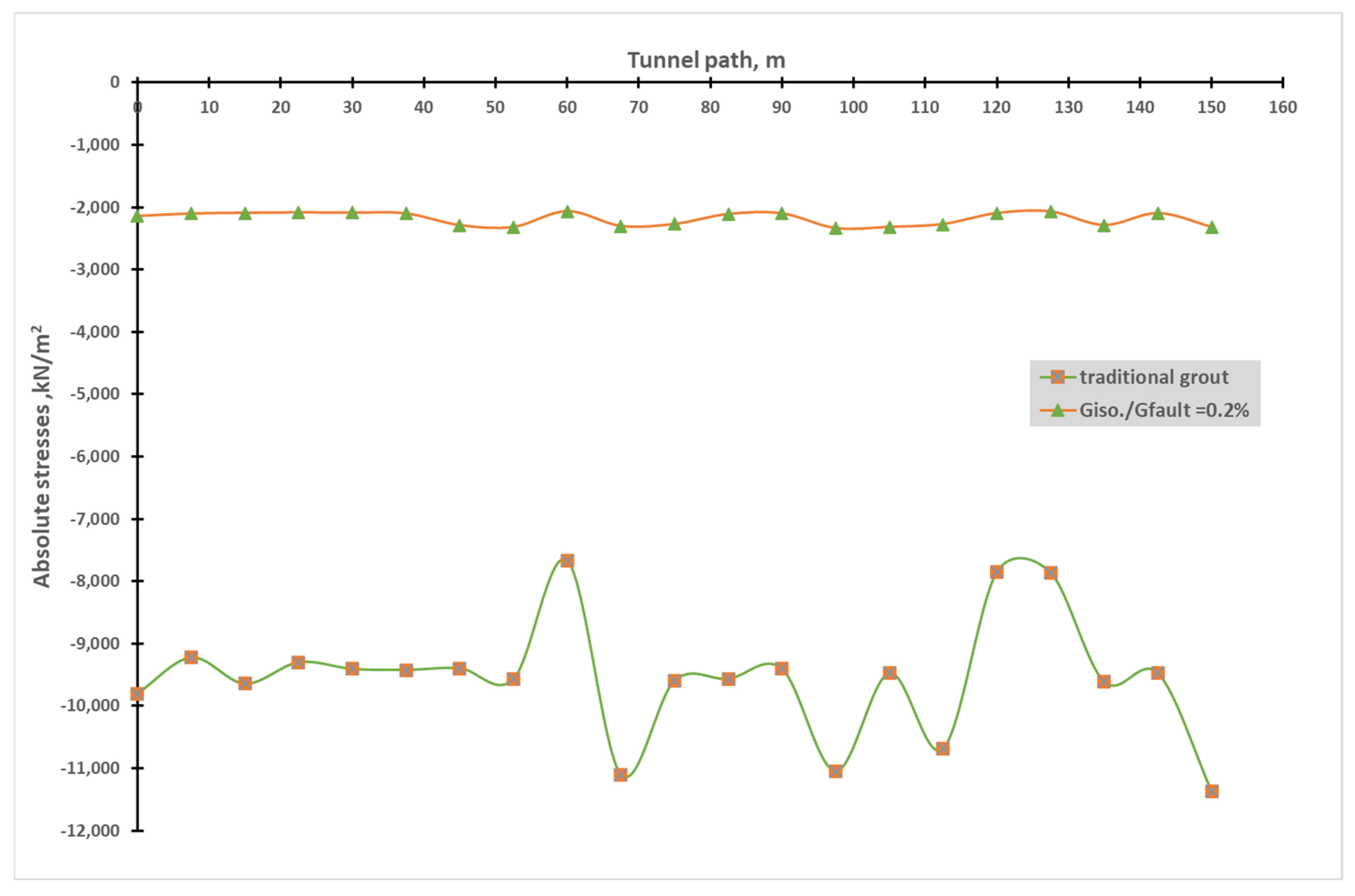
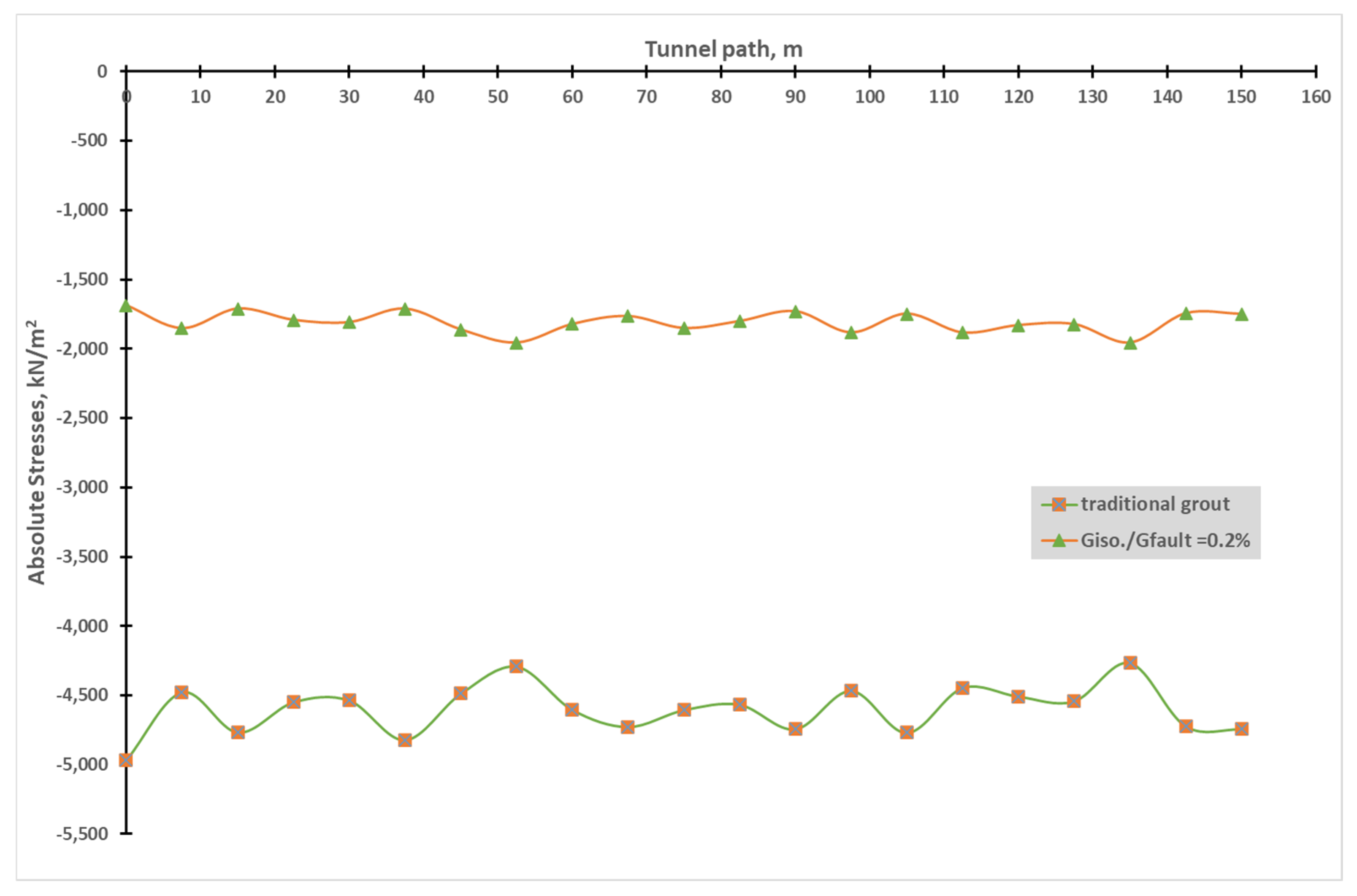
| Giso/Grock = 0.2% | 12,500 | 0.35 | 11.50 |
| Giso/Grock = 0.1% | 6250 | 0.35 | 11.50 |
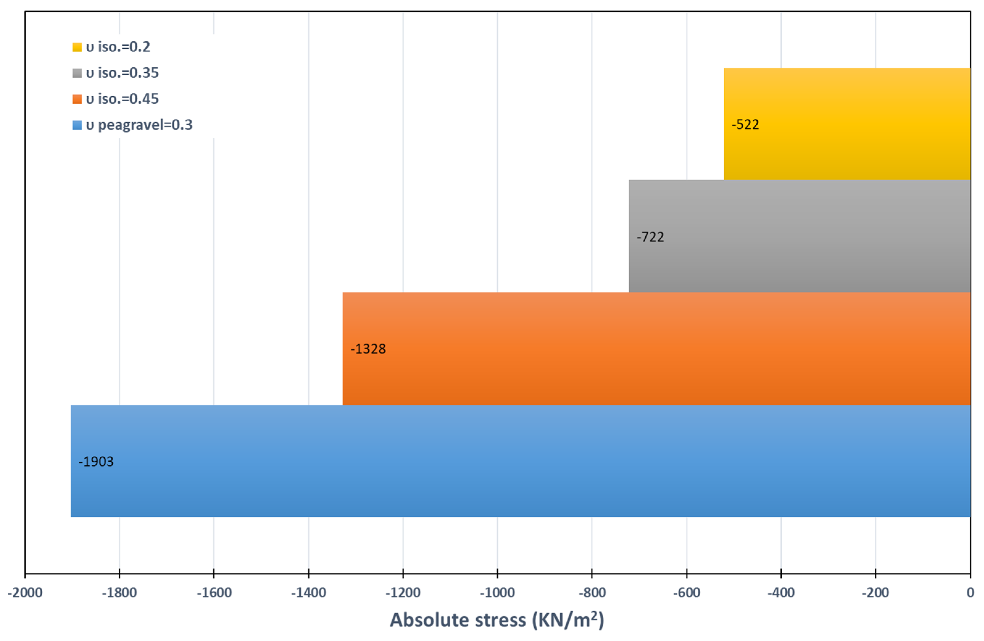
| νiso = 0.45 | 12,500 | 0.45 | 11.50 |
| νiso = 0.35 | 12,500 | 0.35 | 11.50 |
| νiso = 0.20 | 12,500 | 0.20 | 11.50 |
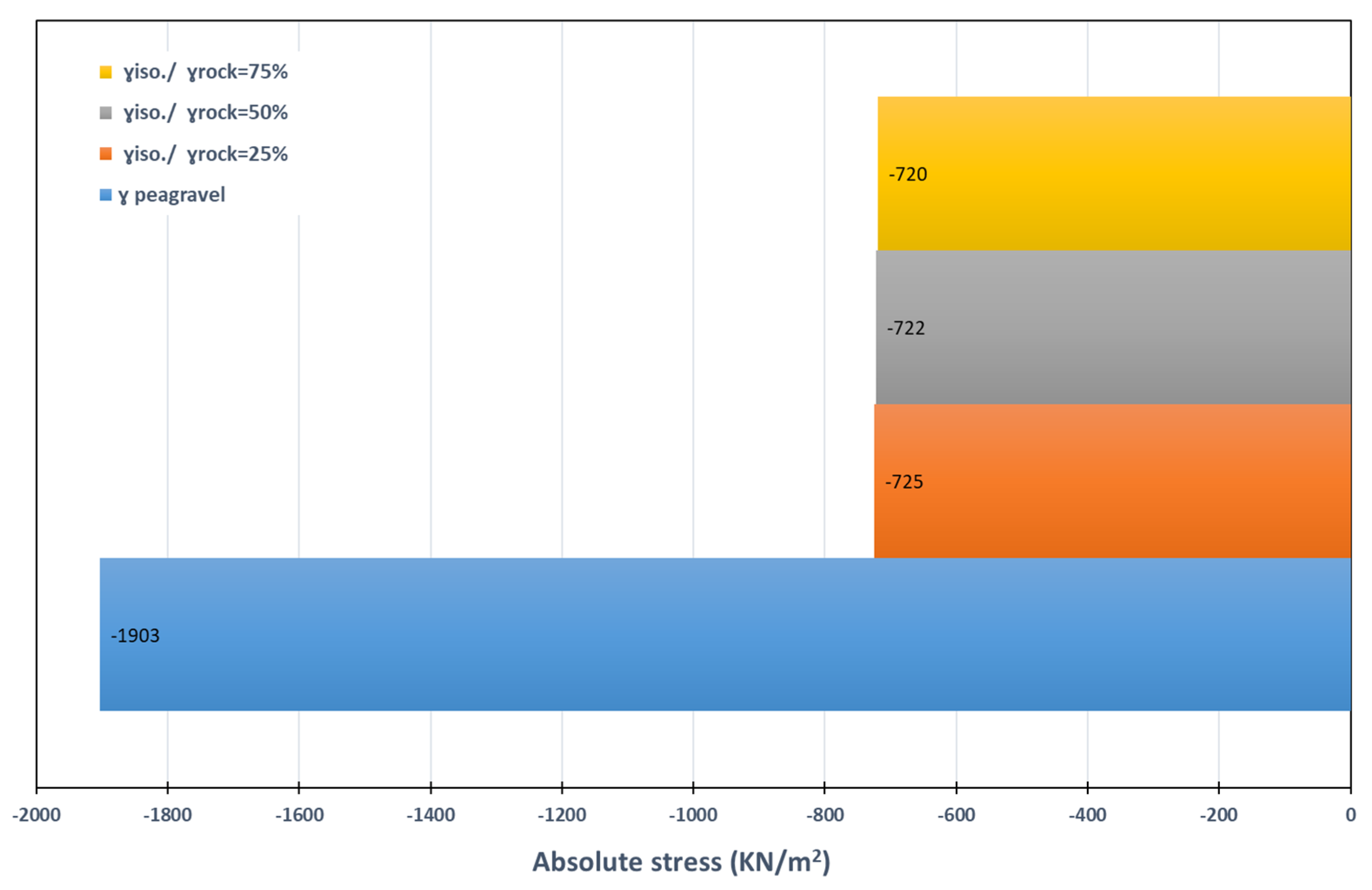
| γiso/γrock = 25% | 12,500 | 0.35 | 5.75 |
| γiso/γrock = 50% | 12,500 | 0.35 | 11.50 |
| γiso/γrock = 75% | 12,500 | 0.35 | 17.50 |
| Material | Modulus of Elasticity (kN/m2) | Poisson’s Ratio | Unit Weight (kN/m3) |
|---|---|---|---|
| Silicon | 500 | 0.48 | 12.00 |
| Geofoam | 4800 | 0.10 | 0.16 |
| Foamed concrete (low E) | 44,720 | 0.35 | 3.00 |
| Foamed concrete (high E) | 760,000 | 0.22 | 7.30 |
| Asphalt | 101,400 | 0.30 | 9.60 |
| Grout/Isolation Descriptions | Absolute Stresses |
|---|---|
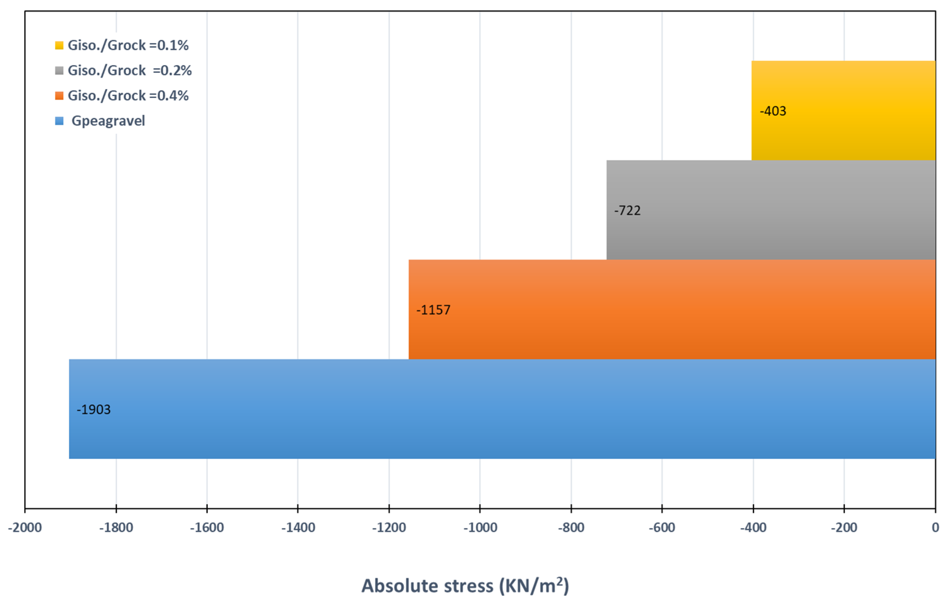
| Giso/Grock = 0.40% | 58–64% |
| Giso/Grock = 0.20% | 34–41% |
| Giso/Grock = 0.10% | 18–24% |
| υiso = 0.45 | 67–73% |
| υiso = 0.35 | 34–41% |
| υiso = 0.20 | 23–31% |
| γiso/γrock = 25% | 34–41% |
| γiso/γrock = 50% | 34–41% |
| γiso/γrock = 75% | 35–41% |
| Silicon | 2–9% |
| Geofoam | 1–10% |
| Foamed concrete (low E) | 62–70% |
| Foamed concrete(high E) | 91–92% |
| Asphalt | 27–101% |
Disclaimer/Publisher’s Note: The statements, opinions and data contained in all publications are solely those of the individual author(s) and contributor(s) and not of MDPI and/or the editor(s). MDPI and/or the editor(s) disclaim responsibility for any injury to people or property resulting from any ideas, methods, instructions or products referred to in the content. |
© 2024 by the authors. Licensee MDPI, Basel, Switzerland. This article is an open access article distributed under the terms and conditions of the Creative Commons Attribution (CC BY) license (https://creativecommons.org/licenses/by/4.0/).
Share and Cite
Elgamal, A.; Elfaris, N. Seismic Isolation Materials for Bored Rock Tunnels: A Parametric Analysis. Infrastructures 2024, 9, 44. https://doi.org/10.3390/infrastructures9030044
Elgamal A, Elfaris N. Seismic Isolation Materials for Bored Rock Tunnels: A Parametric Analysis. Infrastructures. 2024; 9(3):44. https://doi.org/10.3390/infrastructures9030044
Chicago/Turabian StyleElgamal, Ahmed, and Nissreen Elfaris. 2024. "Seismic Isolation Materials for Bored Rock Tunnels: A Parametric Analysis" Infrastructures 9, no. 3: 44. https://doi.org/10.3390/infrastructures9030044