Article

Intrinsic Properties of Composite Double Layer Grid Superstructures †

1
Digital Innovation in Construction Engineering (DICE) Technologies, Calgary, AB T3N 0B3, Canada
2
Department of Digital Engineering and Construction, Karlsruhe Institute of Technology, 76131 Karlsruhe, Germany
*
Author to whom correspondence should be addressed.
This paper was presented at the 10th International Conference on Short and Medium Span Bridges in Quebec City, Quebec, Canada, 31 July–3 August 2018. It has been selected for publication in this journal.
Infrastructures 2023, 8(9), 129; https://doi.org/10.3390/infrastructures8090129
Submission received: 7 July 2023 / Revised: 23 August 2023 / Accepted: 24 August 2023 / Published: 25 August 2023

Abstract

:
This paper examined the opportunities of composite double-layer grid superstructures in short-to-medium span bridge decks. It was empirically shown here that a double-layer grid deck system in composite action with a thin layer of two−way reinforced concrete slab introduced several structural advantages over the conventional composite plate-girder superstructure system. These advantages included improved seismic performance, increased structural rigidity, reduced deck vibration, increased failure capacity, and so on. Optimally proportioned space grid superstructures were found to be less prone to progressive collapse, increasing structural reliability and resilience, while reducing the risk of sudden failure. Through a set of dynamic time-series experiments, considerable enhancement in load transfer efficiency in the transverse direction under dynamic truck loading was gained. Furthermore, the multi-objective generative optimization of the proposed spatial grid bridge (with integral variable depth) using evolutionary optimization methods was examined. Finally, comprehensive discussions were given on: (i) mechanical properties, such as fatigue behavior, corrosion, durability, and behavior in cold environments; (ii) health monitoring aspects, such as ease of inspection, maintenance, and access for the installation of remote monitoring devices; (iii) sustainability considerations, such as reduction of embodied Carbon and energy due to reduced material waste, along with ease of demolition, deconstruction and reuse after lifecycle design; and (iv) lean management aspects, such as support for industrialized construction and mass customization. It was concluded that the proposed spatial grid system shows promise for building essential and sustainable infrastructures of the future.

1. Introduction

Skeletal space structures are composed of a highly redundant set of elements, arranged in the form of single-, double-, or triple-layer flat grids, braced barrel vaults, and braced domes. These systems have been used extensively to cover large spaces [1,2,3]. They were extensively used to aid with the reconstruction needs after World War II due to their reduced material consumption, ease and speed of fabrication and erection, high structural redundancy, and economical mass production through industrialization. Later, attributed to the change in construction demands, the advent of emerging construction methods and materials [4,5], and advancements in digitization and computational technologies [6,7,8,9], spatial structures were used to create innovative structural forms with unique geometric characters, such as free-form structures [10,11]. This latter property together with lean manufacturing principles [12,13] paved the path for the possibility of utilizing spatial structures for mass customization efforts in the construction industry [14,15].
In terms of bridges, planar truss bridges with steel or cast−iron beam elements have been built since the Industrial Revolution due to durability, ease of assembly, and erection. In fact, some efforts in terms of fatigue considerations, seismic response, and lifecycle extension through design for planar truss bridges were reported in [16,17,18], respectively. However, the application of 3-dimensional (3D) modular and lightweight skeletal spatial structure systems for fast construction, durable and circular bridge infrastructures was not investigated outside of the work of the authors [19,20,21]. To this end, this study investigated the potentialities of skeletal space structures in relation to a largely disregarded area of application, namely, short to medium-span bridge superstructures. This study aims to capitalize on the many advantages of 3D modular skeletal spatial structure systems, such as low weight, high structural redundancy and reliability, and mass customization in bridge superstructures. In particular, this study focuses on the advantages of utilizing composite double-layer grid superstructure (CDLGS) over the common composite plate-girder superstructure (CPGS) in application areas where little attention was given [19,20,21]. While the proposed deck system can be adopted irrespective of the bridge typology, here, the feasibility of utilizing modular CDLGS as an alternative to traditional beam bridge structures (the CPGS) was investigated. This study extends on the preliminary investigations of the authors, presented at the 10th International Conference on Short and Medium Span Bridges 2018, by including: (i) new investigations on single and multi-span bridges; (ii) generative design optimization of a newly proposed variable depth integral CDLGS; and (iii) practical operation and management considerations, such as lean construction management, health monitoring and maintenance, and sustainability.
In this manuscript, through a series of experiments, it will be empirically demonstrated that the CDLGS (in different configurations; see Section 2.2) provides a viable alternative to the CPGS system improving important aspects, such as sustainability (e.g., embodied energy and Carbon), affordability, accessibility for infrastructure maintenance and management, ease of construction erection and disassembly, and potentiality for industrialization and mass production.

2. Bridge Decks Composed of Double Layer Grids and Reinforced Concrete Decking

2.1. Characteristics of the Proposed CDLGS

Short-span bridges have been built typically and in large numbers for years with the use of prefabricated reinforced and/or prestressed concrete beams or steel plate girders together with in-situ reinforced concrete topping to form a variety of composite construction decks. In this study, the CDLGS deck is proposed as an alternative to the typical CPGS composite beam bridges. The proposed CDLGS bridge is composed of a 3D double-layer spatial grid system, arranged using modular polyhedron members (e.g., rectangular/square pyramid, hexagonal pyramid, or tetrahedron) in composite action with a thin layer of planar reinforced concrete slab. Figure 1a shows the typical double-layer skeletal spatial structure grid modules with steel elements in the square pyramid arrangement used in this study. Figure 1b,c show the compressive test on a single module, and a 10 × 10 m2 double-layer grid, respectively. Here, the results of the mechanical behavior of these modules, reported in detail in [22,23], were utilized to realistically simulate and model the behavior of these modules. Figure 1d,e show examples of digital modeling of single-span and multi-span bridges of CDLGS nature, respectively.

2.2. Experimental Description

In the remainder of this section, a set of experiments were designed and completed. Among these investigations, first, the particulars of a single-span bridge were considered, and, then the general case of continuous superstructures was investigated. Furthermore, the impact of the number and length of spans, load transfer effects in traverse direction, and earthquake vertical component on the CDLGS and CPGS (benchmark) were examined. Finally, the topic of design optimization of a new variable depth-CDLGS bridge based on various important, but conflicting factors using the established evolutionary algorithm, called, non-dominant Genetic Algorithm (NSGA II) [24,25], was explored. In all cases, the modeling, finite-element analysis, and generative optimization were performed using Formian [26], SAP−2000 [27], and Matlab, respectively. Based on the computational and numerical analysis of the structures, their long-term mechanical behavior, construction management, and fabrication and erection considerations, along with related aspects of sustainability were discussed.
Figure 2 shows the digital models of the CDLGS and CPGS bridges of single, double, triple, and quintuple-span bridges. These models were utilized in different configurations, such as span lengths throughout the experiments (more details on the configurations can be found in each experiment). Table 1 provides the summary of the areas of application, and metrics of validation used for comparison and analysis.

2.3. Single Span Bridges with CDGLS Deck System

Here, we refer to Figure 1d and Figure 2a and examine how a double-layer grid system in composite action with a rather thin layer of reinforced concrete decking can make a considerable difference. For the sake of comparison, we consider a customary type of single-span bridge superstructure consisting of plate girder stringer beams in composite action with a concrete slab, as our benchmark bridge.

2.3.1. Experiment Setup

A series of beam and slab bridges were designed as typical bridges with different numbers of spans and span lengths and were built with minimal modifications across the country of Iran. Here, two single-span benchmark bridges with different span lengths of 22.5 m and 30 m have been considered. The bridges consisted of 1560 mm and 2060 mm deep plate girder stringer beams located at a center-on-center distance of 1800 mm with 200 mm reinforced concrete slab decking. Adopting a normal design practice under the AASHTO standard practices [28,29], while satisfying the Code of Practice for Space Structures [30], a square on square regular rectangular double layer grid consisting of 1760 mm typical pyramidal units was designed for the 22.5 m span bridge. For the 30 m span bridge, the module dimension was taken as 2380 mm. Here, the module dimension applies to the longitudinal and transversal subdivisions as well as the center-on-center distance of the top and bottom layers. With the consideration of the two-way action of the continuous slab deck resting on rather small modules, it was required to take a slab thickness just sufficient for punching shear. The deformed shape of the single-span and two-span CDGLS deck system is schematically presented in Figure 3 for reference.

2.3.2. Result of Comparison with Benchmark Deck

The results of the comparison may be surprising to many bridge engineers. Consider the case of two-stage analysis, design, and construction of the system consisting of the following stages:
  • Stage (1): where the double layer grid should bear its own weight plus the weight of fresh concrete and probable additional construction loads, followed by;
  • Stage (2): in which the composite system after the hardening of concrete should resist any additional dead weight of paving, piping, guard rails, etc., together with live loads on the bridge.
Using the double−layer composite grid system, the weight of steel was reduced to about 43% of the benchmark bridge in the case of the 22.5 m span bridge and to 39% of the original in the case of the 30 m span bridge. Also, live load displacements were reduced by 20% for the 22.5 m and by 28% for the 30 m models [20,21,31] and thus the chance of deck vibration usually observed in composite beam and slab bridges will be reduced. It is quite an easy task to introduce an initial camber to the double−layer grid to limit displacements even further. Optimizing the distance between the transverse grid lines can also lead to a more reduced weight.
Now that the proposed system allows the use of a 120 mm reinforced concrete deck slab in place of the 200 mm slab used in the benchmark bridges, the reduction in concrete consumption of decking becomes 40%. Moreover, if the situation allows the construction of the composite double-layer grid on an elevated ground at one side of the bridge site to be pushed to position with the use of a front runner truss, or the condition permits supporting the space grid temporarily by scaffolding until the concrete hardens, the weight of space grid will be reduced further. In this case, the steel material consumption would be about 33% and 27% of the original benchmark bridges for 22.5 m and 30 m long-span bridges respectively. Here, due to the 3D nature of the behavior of the system, the lateral distribution of concentrated loads acting asymmetrically is much improved compared with the customary beam and slab bridges [32]. Also, due to high redundancy, well-proportioned space structures are less prone to progressive collapse and provide much higher reliability in design, reducing the risk of sudden failure [23,33].

2.4. Extension to Continuous Superstructures Supported by Reinforced Concrete Bents

Assume that a composite double−layer grid system, as discussed above, is now employed as a deck system for a rather regular continuous multi-span bridge, supported by reinforced concrete bents, as shown in Figure 1e. Here, to avoid any complications, the depth of the double-layer grid system is taken as constant. Further assume that the superstructure is supported on elastomeric bearings allowing longitudinal movements, except at an abutment and/or selected piers, but constraining the lateral displacement of the deck to the supporting bents at the locations of supports. Now consider the component of ground motion in the transverse direction. For such regular bridges, it is customary in preliminary design to carry out a preliminary equivalent static analysis, according to AASHTO [28], for non-busy highway bridges, the earthquake forces are considered to be proportional to the dead weight of the bridge.

2.4.1. Weight Reduction Compared to Benchmark

The dead weight of such a composite double−layered grid has been found to be about 30–40% of the customary beam and slab system consisting of composite plate girders with 20 to 30 m long spans. This will be even more pronounced in comparison with voided slab-reinforced concrete superstructures. Accordingly, the equivalent static earthquake forces will be reduced substantially.

2.4.2. Seismic Response Compared to Benchmark

If we keep the stiffness of the bents as it was in the customary bridge, due to lesser mass, the period of vibration will also be reduced. However, in actual practice, the designer proportions the stiffness of the bent accordingly. Hence, an increase in the related response coefficient due to a reduction in period is not expected to be as influential as the effect of a considerable reduction of the dead load. With the consideration of the soil condition and the influence of soil-structure interaction, we still expect a considerably lesser equivalent static earthquake force in our preliminary design. The seismic behavior of bridges with double-layer grid superstructures were studied compared to conventional beam and slab bridges considering 3- and 5-span bridges with 22 and 44 m equal span lengths [34]. The time history analysis results were carried out under the action of 11 recorded time histories of severe earthquakes scaled to values of fractions of the gravitational acceleration, g, (i.e., 0.3 g, 0.5 g, and 0.7 g). For instance, Figure 4a–c show the results of the base shear in the transversal direction for the 0.3 g, 0.5 g, and 0.7 g magnifications of the Tabas earthquake, respectively.
The results demonstrated that the averages of the maximum values of the base shears in the lateral direction for bridges with composite double-layer gride superstructures were considerably less than those of the corresponding composite plate girder string beam and slab bridges. To exemplify, considering the 3- and 5-span bridges with equal spans of 44 m, the maximum calculated average base shears in the lateral direction for the bridges with composite double-layer grid superstructures were found to be, respectively, 42% and 51% less than those of the bridges with steel beam and slab superstructures. Indeed, the lower dead load of the composite double-layer superstructure in association with the resulting reduced seismic response will combinatorically lead to a considerable reduction in the dimensions of the piers and foundations as well, leading to much lower construction costs and efforts. Since the upper layer of the superstructure is acting together with the reinforced concrete slab, their slenderness is not of concern. By limiting a few compression members in the vicinity of supports, controllable stiffness, and ductility can be achieved.

2.5. Impact of Number and Lengths of Spans

2.5.1. Experiment Configuration

Additional investigations focused on increasing the bridge span from one to three spans with identical widths of 12 m while considering four separate span lengths of 20, 26, 32, and 40 m. The 2- and 3-span continuous bridges were supported by reinforced concrete bents through appropriate elastomeric bearings. The concrete topping slab was 200 mm thick, however, as discussed, the slab thickness could be reduced due to the two−way slab action of the CDLGS. This two-way slab action reduces the dead load demand and consequentially reduces the consumed concrete. Here, steel class ASTM A615 [35] along with normal strength concrete with characteristic compressive strength [36] of 300 N/mm2 was assumed in all cases. The configurations used for the CPGS and CDLGS were as follows:
  • CPGS bridge configurations: The lateral distance between the stringer beams was taken at 2 m and, the heights of plate girders were taken as 1/20 of the span lengths. The longitudinal distance between the transverse vertical diaphragms for the CPGS was between 5 to 6 m.
  • CDLGS bridge configurations: The transversal subdivisions were considered at 2 m and the longitudinal subdivisions were equal to 2, 2.6, 3.2, and 4 m for the 20, 26, 32, and 40m span bridges, respectively. Three different ratios of the heights of superstructures to span lengths of 1/12.5, 1/15, and 1/17.5 were investigated for each span length (a total of 12 cases).

2.5.2. Weight Reduction Compared to Benchmark

It was observed that the rigidity of the deeper CDLGS was higher than CPGS. Furthermore, in all cases, the maximum live load displacements of the CDLGS were well below the permissible live load displacements specified by AASHTO [28]. In terms of material consumption, the results can be summarized as follows:
  • Single-span bridges: The reduction in steel material consumption was calculated as 33%, 36%, 40%, and 43% for the 20, 26, 32, and 40 m bridge spans, respectively.
  • Two-span bridges: The weight of steel reduction was higher, ranging from 45%, 47%, 50%, and 52% for 2 × 20, 2 × 26, 2 × 32, and 2 × 40 m span bridges, respectively.
  • Three-span bridges: The reduction was even higher ranging from 47%, 50%, 52%, and 56% for 3 × 20, 3 × 26, 3 × 32, and 3 × 40 m span bridges, respectively.
In the range of span lengths under investigation, it was observed that the weight of steel per unit area of superstructure increased almost linearly as the span length increased for both systems. The rate of increase of material, however, was considerably smaller in the CDLGS, compared to the CPGS. As such, the use of the latter benchmark system becomes inefficient for larger spans. Furthermore, it was observed that as the span length and the number of spans increased, greater saving in steel consumption was achieved. Through deductive reasoning, it is, hence, expected that the higher the number of spans of a continuous CDLGS system, the greater the material reduction compared with the corresponding benchmark bridge.

2.6. Load Transfer in the Traverse Direction

2.6.1. Experiment Configuration

Through a series of static and dynamic vibration analyses, the present section investigated the load transfer efficiency of CDLGS under passing truck loading to AASHTO [28]. The widely used CPGS was employed as a benchmark for comparison. The HL-93 truck passing through the dark−blue lane, shown in Figure 5a is utilized. As a point of reference, the ratio of the weight of the HL-93 truck (roughly 33 tons) to the weight of the designed CDLGS (roughly 193 tons) was around 17%. Furthermore, Figure 5a, the plan view of Figure 2c, shows the two points that were chosen to assess the load transfer capabilities of both systems in the transverse direction. One of the points, Point 1, was a mid-span point lying under the longitudinal axis of the passing truck, and the other, Point 2, was selected at the mid-span of the bridge near the unloaded edge of the superstructure. The linear elastic dynamic analysis was performed for the extreme vehicle speed of 40 m/s. For the composite steel-concrete constructions in the analysis, the damping ratio of 0.04 was considered.

2.6.2. Load Transfer Efficiency Compared to Benchmark

Figure 5b,c show the results of the load transfer efficiency test, represented by the deflection time-series of the two considered points for the CPGS and CDLGS, respectively. By virtue of its nature, the displacement in Point 1, which is directly beneath the truck’s path, is larger than that of Point 2. As observed from the amplitude of the deflections, the load transfer efficiency in the transverse direction of the CDLGS is far superior to the benchmark, CPGS with intermediate vertical diaphragms.

2.7. Effect of the Vertical Component of Earthquake Ground Motion

2.7.1. Experimental Setup

Here, this effect was investigated by performing the pushover as well as the nonlinear dynamic analyses on both the CDLGS and CPGS systems. Single-span and two-span bridges (Figure 2a,b) with 20, 30, and 40 m span lengths were considered for the analysis. The superstructure width was taken as 10 m in all cases. ASTM A283 steel was used in all cases. The following configurations for CDLGS and benchmark CPGS were taken:
  • CPGS bridge configurations: The span-to-length ratio was considered as 20. The side-by-side distance of the stringer beams was 2 m. The slab thickness was calculated as 180 mm and taken as 200 mm for the analysis to account for the one-way behavior and arching action in CPGS bridges. The distance between the transverse vertical diaphragms was set as 5 m in all cases for the CPGS.
  • CDLGS bridge configurations: The span length to depth ratios were taken as 16. Regular 2 × 2 m modules (Figure 1a) were employed. The slab thickness was calculated as 120 mm controlled by punching shear, however, increased to 150 mm to preserve practicality and durability.

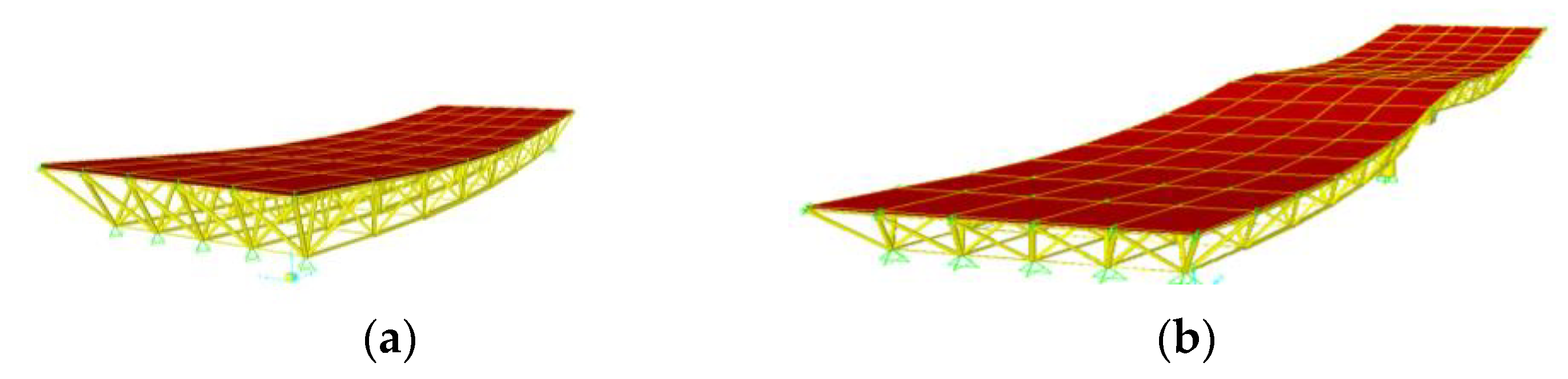
2.7.2. Space Grid CDLGS Member Modelling

Figure 6a provides the idealizations for each space grid member. The members were defined as a combination of a three-node line-element with the capability of geometric nonlinearity at the middle node along with two linearly elastic beam elements where each end was defined as hinged. The choice of such member modeling was made as a result of a study on the suitability of a number of models [23,30,33]. A practical range of values of the slenderness ratios, were considered (i.e., 50, 80, 120 and 200). Joint flexibility was adopted through [21]. A Formax [26,37] approach to sub-structuring, presented in [23,33] was adopted, which is shown suitable for modular structures, such as the CDLGS. The member’s initial imperfection was modeled through the introduction of the initial eccentricity e 0 , shown in Figure 6b. The influence of the eccentricity on the load-displacement response curve of a member is shown in Figure 6c as reference. For this, a bilinear material model along with a damping ratio of 0.04 for the composite steel-concrete constructions under investigation were considered.

2.7.3. Nonlinear Static Analyses Results

First, a pushover analysis under displacement control conditions that preserve the fundamental mode (dominant) of vibration in the vertical direction was performed. To consider the cyclic nature of continuous load reversal in actual earthquake excitations, the following two cases were considered:
  • push from the top towards the bottom, in which the incremental loading was applied in the same direction as the gravity loading (Figure 7a); and
  • push from the bottom towards the top, in which the incremental loading was applied in the opposite direction of the gravity loading.
Figure 7b represents the results of the pushover analyses for two span superstructures with 20, 30, and 40 m span lengths in terms of the capacity (in excess of the dead loads) versus maximum vertical displacement near the midspan. Focusing on strength, stiffness, and ductility, single-span bridges behaved well. However, the bottom layer members in two-span bridges required strengthening in the vicinity of the middle piers when exposed to push from top to bottom (case 1). This was solved by restricting (increasing) the slenderness ratios for these members. Furthermore, no strengthening was required at and near the middle support for the case when pushing was applied from the bottom towards the top (case 2). This was attributed to the presence of compressive concrete at the middle support after counteracting the gravity loading. Finally, it was observed that the superstructure could undergo sufficient plastic deformation considering: (i) the composite action of the top layer of the space grid with the reinforcing steel of the concrete slab-even after concrete cracking-, while (ii) the bottom layer performed acceptably well by limiting the member slenderness ratios to achieve a controllable ductility.

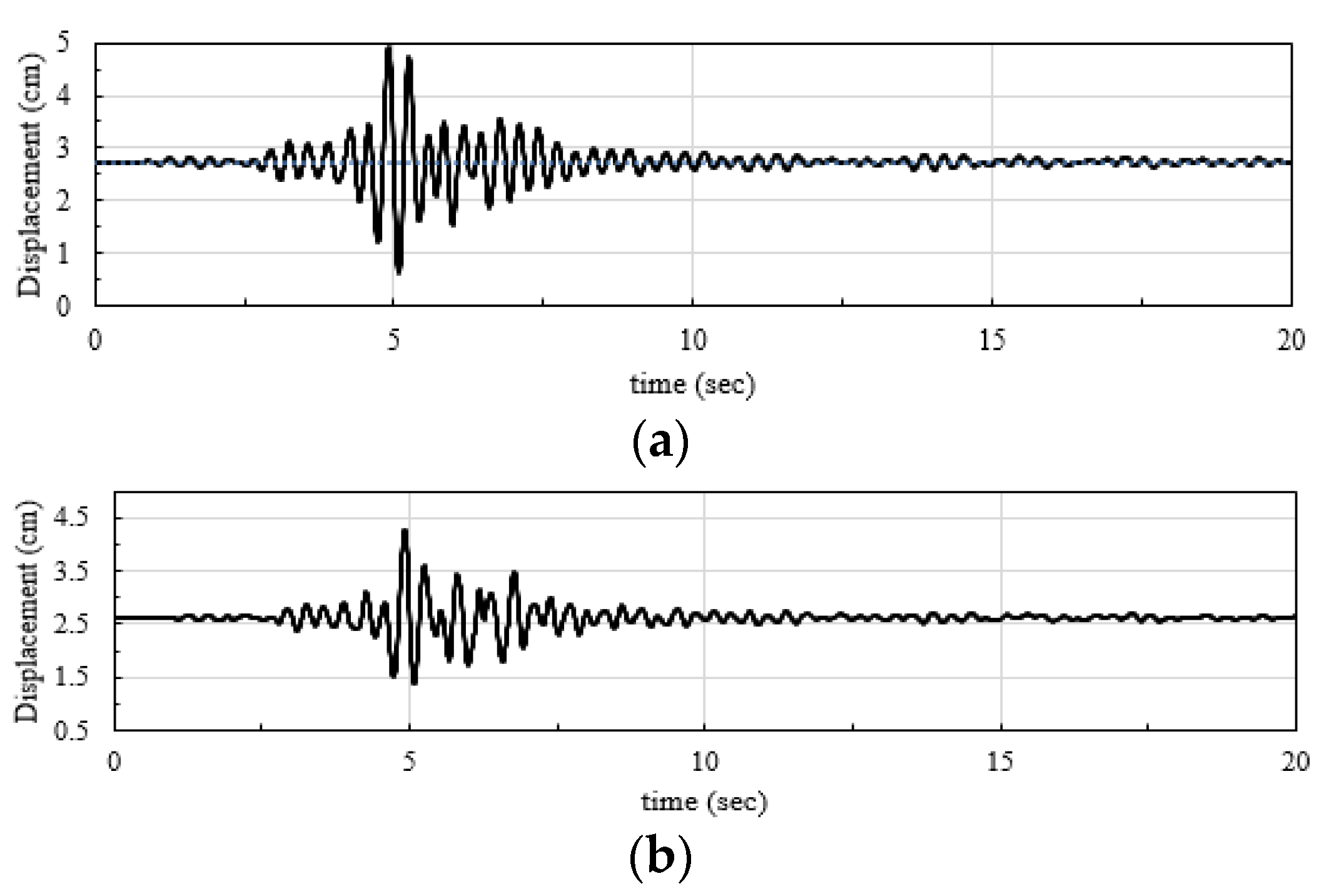
2.7.4. Nonlinear Dynamic Analyses Results

A series of nonlinear time history analyses were carried out under the application of the vertical component of earthquake excitation for all bridge configurations introduced in Section 2.5.1. Identical excitation was assumed at all the supports. The corresponding analysis was performed under the Kobe earthquake data with the peak acceleration in the vertical direction of 0.43 g, where g is the gravitational acceleration. Sample results for 40 m long two-span CPGS (benchmark) and CDLGS bridges are shown in Figure 8a,b, respectively. It was observed that the maximum calculated displacement amplitude in the case of the CDLGS was 55% of the corresponding value for the CPGS. Similarly, the maximum stress range of members of the CDLGS was found to be considerably smaller than that at critical locations of the sample CPGS design.

2.8. Multi-Objective Design Optimization

So far, it was observed that the application of the composite double-layer grid superstructures (CDLGS) as short to medium-span bridge superstructures led to a desirable overall behavior compared to the conventional CPGS. During the current investigations, the authors found that the benefit will be even more pronounced in skewed bridges. Further improvements will be gained by adopting variable depths along the double-layer grid [38]. Figure 9a shows a sample 3D design of such bridges consisting of variable depth composite grid superstructure with integral spatial grid piers, hereon referred to as the integral variable depth composite double layer grid system (IVD-CDLGS). The goal of this section is to optimize the design of the IVD-CDLGS using NSGA II to satisfy multiple (and conflicting) objectives, namely, weight (representing embodied energy and Carbon [39,40,41]), fundamental frequency, strain energy, and cost of construction. In this case, the fundamental frequency must be maximized, while the weight, strain energy, and construction cost must be minimized.

2.8.1. Design Optimization Setup

Figure 6b shows the nine (9) decision variables for the multi-objective optimization. The size of the bridge in terms of height and length of spans (for the three spans) were taken (fixed) as 20 and 25-50-25 m, respectively. Amongst the nine (9) decision variables used, two, namely, k and l , were integers. The range and constraints of these variables are as follows:
{ 4 r b 3 6 0.5 r b 1 , r b 2 r b 3 1 h c ( 20 r b 3 ) .0.8 1 r c 2 min ( r c 3 , r c 1 ) 2 r c 3 , r c 1 10 10 k 60   ( i n t e g e r ) 3 l 10   ( i n t e g e r ) ,
Given the multi-objective nature of the problem, and the complexity of the decision variables, traditional and deterministic gradient-based minimizations will fail since a single optimum solution may not be available. To this end, the NSGA II heuristic evolutionary multi-objective optimization was utilized to generate many Pareto optimal solutions (also referred to as Pareto Front). Here, 100 Pareto front solutions were generated using the NSGA II algorithm.

2.8.2. Design Optimization Results

Figure 10 shows the optimal solutions obtained from the NSGA II algorithm for the problem under consideration. Figure 7a shows the resulting design that maximizes the fundamental frequency (without considering the other objectives). Consequentially, Figure 10b–d shows the resulting designs that minimizes strain energy, weight of consumed material, and construction cost. Some visual interpretations of the results were made as follows. The design shape in Figure 10a suggests that the increase in the vertical divisions of the piers, l , leads to optimal performance in terms of fundamental frequency. The shape in Figure 10b suggested that the performance in terms of strain energy improved when the number of subdivisions decreased, and the depth variation for both deck and piers increased. The design that minimized the weight (Figure 10c) demonstrated that the increase in the number of horizontal subdivisions while reducing the depth variation, can lead to less material consumption. Figure 10d shows that the length of installed members decreased when the depth variation and horizontal subdivisions increased. These observations also show that one single design cannot satisfy all objectives simultaneously. As such, with the assumption that all objectives have equal importance, the best design was found and shown in Figure 10e. This design has some properties from all the best individual designs, such as decreased depth variation, increased pier width, and so on.
As a point of reference, the modal eigenvalue analysis of the best overall design (Figure 10e) was performed and shown in Figure 11 for the first four mode shapes.

3. Discussions: General Construction and Functionality Considerations

Practical construction considerations of the proposed system in terms of corrosion, maintenance, inspection and health monitoring, fatigue behavior, erection strategies, industrialized mass production, quality control, economic development, and sustainability are discussed in the following.

3.1. Further Design Considerations

In the case of short bridges with short to medium length spans on closed abutments, the CDGLS is sufficiently stiff to prevent large lateral displacements. As such, the short CDGLS can act as an effective diaphragm in the plane of the deck without causing unwanted longitudinal support actions. In such cases, it may not be necessary to design the bents for lateral seismic actions. If the deck, however, is designed to move freely with respect to its supporting bents but kept restrained at both abutments against lateral movements, the abutments and their supports can be effectively designed to take the full lateral seismic forces. In such cases, considering the light weight of the superstructure by design, concerns may arise in relation to their performance under the action of wind against uplift, overturning, etc.; hence, the authors are currently investigating the behavior of such bridges under extreme wind conditions. The results obtained until now, particularly for aerodynamic optimization of the drag and lift coefficients, have been promising.

3.2. Corrosion

In this case, suitable strategies may be employed for different climatic conditions. Such space grids may be protected by painting or hot-dip galvanization of the members and joints during production and manufacturing. In severe conditions, stainless still may be used for susceptible and at-risk parts of the structure.

3.3. Maintenance, Inspection, and Health Monitoring

Ease of inspection and maintenance is an important advantage for taking timely preventive measures. Mechanical and Electrical facilities may be passed through the space between the double layers with no difficulties. Consequently, drainage is a simple task. Any required super-elevation can be accommodated in the design. Almost all parts of the structure are available for easy access for the installation of health monitoring devices, such as strain gauges, fiber optic sensors, and accelerometers, along with optical metrology for visual assessment [42] through smartphones and mobile laser scanners [43]. These devices can not only facilitate the development of digital twins [44,45] of the infrastructure in real-time (or near real-time) but also foster the incorporation of digital technologies within lifecycle civil integrated management (CIM) best practices [46,47].

3.4. Fatigue

The fatigue behavior of joints needs careful investigation. It seems that by means of conceptually sound design and detailing of joints the risk of fatigue failure associated with welded plate girder stringer beams could be reduced. Comprehensive programs of work should be conducted before any design recommendations can be given in that respect. In cold environments, the risk of brittle fracture increases, particularly when extraordinarily the temperature reduces to a value less than the material transition temperature. In damp and aggressive climates, special measures need to be taken to prevent or minimize the effects of corrosion fatigue and/or stress corrosion. The authors are currently conducting an experimental and numerical investigation of the fatigue behavior of a variety of space grid joints aiming at possible improvements to ensure the safe fatigue life of the bridge superstructure system under consideration.

3.5. Mass Production and Industrialization

In the mass production of typical bridges, urgently needed in developing countries to expand their infrastructure, there will be a need for an initial expenditure for the construction of a manufacturing plant to serve a decided area for a decided number of years. Hence, management decision-making should consider not only the initial cost but also the costs of normal activities and maintenance of the plant as well as the life cycle costs of the fabricated and erected projects. The immediate and short−term answer to the question of construction of just a small number of bridges along a single road is to choose one of the immediately available methods of construction of customary bridges. This is because in the framework of a single project, the initial expenditure and time required for the construction of the manufacturing plant may not be justifiable. As such, this must be decided on a much wider area of strategic planning for the development and extension of regional infrastructures. Using a realistic economic model, a simple analysis-accounting for the initial investment-will prevail over the economic advantage of the proposed double-layer grid system after a few years of production. For many countries, within strategic planning of the development of their infrastructures, value engineering, and target value design charrettes/workshops may be formed. Site selection for such production factories can be optimized within an initial feasibility study based on project demand and schedule. Each factory can be planned to serve a region and can be programmed to produce continuously in 3 shifts. Further capacity and location optimization [48,49,50] can be performed to satisfy multiple criteria, such as embodied energy, affordability, pace of construction, etc. using evolutionary optimization strategies, such as the NSGA II discussed in Section 2.6. Under efficient management, the initial expenditure per meter of the constructed deck falls sharply in a short period of time.

3.6. Quality Control

The possibility of applying the principles of industrial management, total quality management [51], operational research, and facility management in a production line will be a great advancement over the tedious cutting and welding of plate girders and their stiffeners on-site for which under the best quality control procedures, weld deficiencies, and distortions the problem may persist. Further quality control strategies may include the utilization of optical metrology devices, such as laser scanners, coupled with advanced, automatic, and reliable structural recognition techniques from point clouds [52,53,54,55] to control the quality of built modules in the manufacturing plant, before they are shipped to site. These strategies have already been shown to be effective in the quality control of mass-customized pipe and flange modules in the Canadian oil and gas industry [56].

3.7. Economic and Affordability Considerations

Regarding the considerable savings in material consumption, ease and speed of fabrication and erection, and other economic advantages mentioned above, with the consideration of a realistic economical model, it has been demonstrated that the initial expenditure necessary for setting up the required production plant will return within a few early years followed by significant savings for a rather long time in the following years. This enables efficient infrastructure development with an optimal utilization of available financial resources. For a given area, a production plant can be provided to serve an area within an optimized distance to the factory to mass produce typical bridges necessary for the development of new highways/railways or replacement of old bridges that are not suited to retrofitting. Permanent work and job security for production workers as well as the inspection and maintenance teams are additional aspects of such an approach. Continuously, well-trained technicians and engineers are the driving force behind the continuous quality improvements in lean management to extend the ideas to deal with a variety of larger scale projects such as the application of double-layer grid deck systems to cable-stayed bridges considering their light weight and high rigidity. These types of structures due to their light weight can be erected with ordinarily available construction equipment; however, multi-span bridges of this type can be built in composite form at shore and pushed to position using a space grid front runner truss where applicable.

3.8. Sustainability

With the consideration of all the above, the construction of bridges of the proposed type is in line with recent environmental awareness to enhance sustainability in design. In place of customary beam and slab bridges, the mass production of many typical straight or skewed bridges all over the world reduces material consumption considerably. This great reduction in material (around 40% as derived above for bridges under consideration) will consequentially reduce both the embodied energy and the embodied Carbon equivalent of construction materials in proportion. These include less harm to the environment and natural resources and the reduction in direct costs of embodied energy (and the associated pollution) required for the production and transportation of additional steel and concrete materials. With the advent of new smart and sustainable materials and strategies to substitute steel and concrete, the environmental impact of these structures can be reduced even further. Durability and maintainability are also other key advantages of the system. Bolted grid-works can be designed to be dismountable for further usage or neat dissembling/recycling if needed. Considering only the material consumption, the amount and cost of materials that we are spending to build one of such customary bridges can be spent to build about three to four bridges of the proposed space grid system. Here, the structural design concept can lead to true resource management in the spread of essential infrastructures for social exchange and economic development for many societies across the globe.

4. Conclusions

The application of a new bridge deck system, referred here to as the Composite Double Layer Grid Superstructure (CDLGS), for short to medium-span bridges was investigated. The advantages and considerations of the CDLGS system were compared with a common type of bridge system as a benchmark, namely, the Composite Plate Girder Superstructure (CPGS). It was observed that the CDLGS system compared to the CPGS considerably improved seismic response, and reduced material consumption—similar to other space frame structures [57]—(both structural steel and required concrete slab cover). Considering its lightweight and high redundancy, an increased reliability against progressive collapse, and enhanced overall bridge seismic performance can be expected. Moreover, the material consumption reduction was found to be even more pronounced for larger spans with a greater number of spans. As such, the light dead weight of the CDLGS encourages the possibility of longer spans. In terms of load transfer efficiency, it was empirically shown that the proposed CDLGS system performed superior to the CPGS in the transverse direction during dynamic truck loading. Nonlinear time-series analysis revealed reduced superstructure seismic displacement under the vertical component of earthquake excitation.
The reduction in material consumption not only reduces the construction cost but also reduces lifecycle embodied carbon, embodied energy, pollution of engineered material manufacturing, and material waste during demolition and disassembly of the bridge, directly supporting sustainability and the environment [58,59]. Further improvements in mechanical properties and weight were found through the design of the variational depth CDLGS deck with integral piers (IVD-CDLGS). Here, the opportunities for multi-objective generative optimization of the IVD-CDLGS bridge system were investigated. Optimal values for nine (9) decision variables to achieve a fair balance between weight (representative of embodied energy and Carbon), strain energy, fundamental frequency, and construction cost, were obtained using the NSGA II algorithm. By virtue of the problem’s nature, the optimization does not yield a single result that maximizes the fundamental frequency and minimizes the rest. However, given the exact weight of importance a-priori, it was possible to find the best solution (here, equal importance was considered). In terms of weight, the best design that minimized weight and achieved a fair balance reduced overall material consumption for steel by 28% and 17% on average, respectively (when compared to the final Pareto front solutions). This result demonstrated considerable material weight reduction from the original CDLGS when the design decision variables of the IVD−CDLGS were optimized. Considering only the material consumption, the cost of materials that is spent to build one CPGS bridge can be spent to build around two or three bridges of the proposed CDLGS and IVD-CDLGS bridge systems, leading to enhanced economic and social development.
To conclude, the skeletal spatial structure systems offer many advantages to satisfy the diverse needs of contemporary societies, combining technical, economic, and environmental aspects to build sustainable and resilient bridges in essential infrastructure development programs. To this end, the proposed system can provide a viable alternative during strategic planning stages for the development and extension of regional infrastructures.

Author Contributions

Conceptualization, S.M. and R.M.; methodology, S.M. and R.M.; software, S.M. and R.M.; validation, R.M., B.M. and S.M.; formal analysis, S.M.; investigation, S.M., B.M. and R.M.; resources, S.M.; data curation, S.M.; writing—original draft preparation, S.M.; writing—review and editing, R.M. and B.M.; visualization, S.M. and R.M.; supervision, S.M.; project administration, S.M.; funding acquisition, S.M. and R.M. All authors have read and agreed to the published version of the manuscript.

Funding

The author wishes to acknowledge the support provided by the KIT Publication Fund of the Karlsruhe Institute of Technology in supplying the APC. This research received no additional external funding.

Data Availability Statement

Research data can be requested from the corresponding author.

Conflicts of Interest

The authors declare no conflict of interest.

References

  1. Behnejad, S.A.; Parke, G.A.R. Half a Century with the Space Structures Research Centre of the University of Surrey. Int. J. Sp. Struct. 2014, 29, 205–214. [Google Scholar] [CrossRef]
  2. Makowski, Z.S. New trends in spatial structures. J. Int. Assoc. Shell Spat. Struct. 1986, 90, 21–43. [Google Scholar]
  3. Parke, G.A.R.; Behnejad, S.A. Z S Makowski: A Pioneer of Space Structures. Int. J. Sp. Struct. 2015, 30, 191–201. [Google Scholar] [CrossRef]
  4. Krishnan, S.; Liao, Y. Geometric Design of Deployable Spatial Structures Made of Three-Dimensional Angulated Members. J. Archit. Eng. 2020, 26, 04020029. [Google Scholar] [CrossRef]
  5. Dev, K.N.; Das, A.K. Design of Bamboo Shelter Kit for Post-Disaster Temporary Shelter Response. In Smart Innovation, Systems and Technologies; Springer: Singapore, 2021; Volume 221. [Google Scholar]
  6. Luo, Y.; Bao, J. A Material-Field Series-Expansion Method for Topology Optimization of Continuum Structures. Comput. Struct. 2019, 225, 106122. [Google Scholar] [CrossRef]
  7. Brütting, J.; Senatore, G.; Fivet, C. Design and Fabrication of a Reusable Kit of Parts for Diverse Structures. Autom. Constr. 2021, 125, 103614. [Google Scholar] [CrossRef]
  8. Rao, S.S. Engineering Optimization: Theory and Practice; John Wiley & Sons Inc.: Hoboken, NJ, USA, 2019. [Google Scholar]
  9. Deb, K. Multi-Objective Optimization Using Evolutionary Algorithms Kalyanmoy; Wiley: Hoboken, NJ, USA, 2001; Volume 16. [Google Scholar]
  10. Chilton, J. Space Grid Structures; Routledge: London, UK, 2007. [Google Scholar]
  11. Schober, H. Transparent Shells: Form, Topology, Structure; Wiley: Hoboken, NJ, USA, 2015. [Google Scholar]
  12. Tzortzopoulos, P.; Kagioglou, M.; Koskela, L. Lean Construction-Core Concepts and New Frontiers; Routledge: London, UK, 2020; Volume 53, ISBN 9780429203732. [Google Scholar]
  13. Baldwin, A.; Bordoli, D. Handbook for Construction Planning and Scheduling; John Wiley & Sons, Ltd.: Hoboken, NJ, USA, 2014; ISBN 9781118838167. [Google Scholar]
  14. Da Silveira, G.; Borenstein, D.; Fogliatto, F.S. Mass Customization: Literature Review and Research Directions. Int. J. Prod. Econ. 2001, 72, 1–13. [Google Scholar] [CrossRef]
  15. Li, X.; Wu, C.; Yang, Z.; Guo, Y.; Jiang, R. Knowledge Graph-Enabled Adaptive Work Packaging Approach in Modular Construction. Knowl.-Based Syst. 2023, 260, 110115. [Google Scholar] [CrossRef]
  16. Bertolesi, E.; Buitrago, M.; Adam, J.M.; Calderón, P.A. Fatigue Assessment of Steel Riveted Railway Bridges: Full-Scale Tests and Analytical Approach. J. Constr. Steel Res. 2021, 182, 106664. [Google Scholar] [CrossRef]
  17. Nettis, A.; Iacovazzo, P.; Raffaele, D.; Uva, G.; Adam, J.M. Displacement-Based Seismic Performance Assessment of Multi-Span Steel Truss Bridges. Eng. Struct. 2022, 254, 113832. [Google Scholar] [CrossRef]
  18. Pipinato, A. Extending the Lifetime of Steel Truss Bridges by Cost-Efficient Strengthening Interventions. Struct. Infrastruct. Eng. 2018, 14, 1611–1627. [Google Scholar] [CrossRef]
  19. Shahbazi-Reveshti, P.; Maalek, S.; Akbari, R. Buckling Behaviour of Composite Double-Layer Braced Barrel Vaults. Proc. Inst. Civ. Eng. Struct. Build. 2022, 175, 387–400. [Google Scholar] [CrossRef]
  20. Maalek, S. Shear Testing of Butt Joints. J. Test. Eval. 2014, 42, 1025–1045. [Google Scholar] [CrossRef]
  21. Ahmadizadeh, M.; Maalek, S. An Investigation of the Effects of Socket Joint Flexibility in Space Structures. J. Constr. Steel Res. 2014, 102, 72–81. [Google Scholar] [CrossRef]
  22. Gholampour, S.; Maalek, S. Experimental Study of the Influence of the Degree of Bolt Tightness on the Effective Length of Compression Members of Double Layer Space Structures Composed of Ball Joints. Modares Civ. Eng. J. 2012, 12, 37–50. [Google Scholar]
  23. Maalek, S. Structural Assessment and Quality Control Procedures for the Homa Aircraft Hangar No. 3. Int. J. Sp. Struct. 1999, 14, 167–184. [Google Scholar] [CrossRef]
  24. Peng, J.; Feng, Y.; Zhang, Q.; Liu, X. Multi-Objective Integrated Optimization Study of Prefabricated Building Projects Introducing Sustainable Levels. Sci. Rep. 2023, 13, 2821. [Google Scholar] [CrossRef] [PubMed]
  25. Deb, K.; Pratap, A.; Agarwal, S.; Meyarivan, T. A Fast and Elitist Multiobjective Genetic Algorithm: NSGA-II. IEEE Trans. Evol. Comput. 2002, 6, 182–197. [Google Scholar] [CrossRef]
  26. Nooshin, H.; Disney, P. Formex Configuration Processing II. Int. J. Sp. Struct. 2001, 16, 1–56. [Google Scholar] [CrossRef]
  27. Computers and Structures Inc. (CSi). SAP2000–Version 14. In Structural and Earthquake Engineering Software; Computers and Structures Inc.: Walnut Creek, CA, USA, 2009. [Google Scholar]
  28. American Association of State Highway and Transportation Officials (AASTHO). LRFD Bride Design Specifications, 9th ed.; AASHTO: Washington, DC, USA, 2020. [Google Scholar]
  29. Maalek, S.; Akbari, R.; Maheri, M.R. The Effect of Higher Modes on the Regularity of Single-Column-Bent Highway Viaducts. Bridg. Struct. 2009, 5, 29–43. [Google Scholar] [CrossRef]
  30. Maalek, S.; Nooshin, H.; Dianat, N.; Abedi, K.; Heristchian, M.; Chenaghlou, M.R. Code of Practice for Skeletal Steel Space Structures; Management and Planning Organization of Iran: Tehran, Iran, 2011. [Google Scholar]
  31. Ghadirli, B.; Maalek, S. A Feasibility Study on the Application of Composite Space Grid to Straight Bridges—A Technical and Economical Investigation. In Proceedings of the 4th National Conference on Spatial Structures, Terhan, Iran, 25–26 May 2014. [Google Scholar]
  32. Heydari-Digehsara, P.; Maalek, S. An Investigation of the Dynamic Vibration Behavior 0f Composite Space Grid Superstructures. In Proceedings of the 6th International Conference on Structures and Earthquakes, Christchurch, New Zealand, 1–4 November 2015; Kerman Bahonar University: Kerman, Iran, 2015. [Google Scholar]
  33. Maalek, S. A Formex Formulation for Substructure Analysis of Open Web Grids. Int. J. Sp. Struct. 1989, 4, 43–64. [Google Scholar] [CrossRef]
  34. Pirhadi, P.; Maalek, S. Seismic Behavior of Bridges with Composite Double Layer Grid Superstructures. In Proceedings of the 11th International Congress on Civil Engineering, Tehran, Iran, 8–10 May 2018. [Google Scholar]
  35. ASTM International ASTM A615; Standard Specification for Deformed and Plain Carbon-Steel Bars for Concrete Reinforcement. ASTM International: West Conshohocken, PA, USA, 2016.
  36. Vu, C.C.; Plé, O.; Weiss, J.; Amitrano, D. Revisiting the Concept of Characteristic Compressive Strength of Concrete. Constr. Build. Mater. 2020, 263, 120126. [Google Scholar] [CrossRef]
  37. Nooshin, H. The Formex Approach. J. Int. Assoc. Shell Spat. Struct. 1988, 96, 25–41. [Google Scholar]
  38. Baqershahi, M.H.; Maalek, S. Dynamic Transverse Load Distribution in Integral Bridges Composed of Tapered Composite Double Layer Superstructure and Tree-Shaped Piers. In Proceedings of the 5th International Conference on Bridges (5IBC 2019), Tehran, Iran, 1–3 May 2019. [Google Scholar]
  39. Jones, C.; Hammond, G. Inventory of Carbon and Energy (ICE); Version 3.0; Sustainable Energy Research Team, Department of Mechanical Engineering, University of Bath: Bath, UK, 2019. [Google Scholar]
  40. Hammond, G.; Jones, C. Embodied Carbon: The Inventory of Carbon and Energy (ICE); Version 2.0; A Building Services Research & Information Association (BSRIA) Guide; Institution of Civil Engineers (ICE): Berkshire, UK, 2011. [Google Scholar]
  41. Hammond, G.P.; Jone, C.I. Inventory of Carbon and Energy (ICE); Version 1.6a; University of Bath: Bath, UK, 2008. [Google Scholar]
  42. Kaartinen, E.; Dunphy, K.; Sadhu, A. LiDAR-Based Structural Health Monitoring: Applications in Civil Infrastructure Systems. Sensors 2022, 22, 4610. [Google Scholar] [CrossRef]
  43. Sánchez-Rodríguez, A.; Riveiro, B.; Soilán, M.; González-deSantos, L.M. Automated Detection and Decomposition of Railway Tunnels from Mobile Laser Scanning Datasets. Autom. Constr. 2018, 96, 171–179. [Google Scholar] [CrossRef]
  44. Boje, C.; Guerriero, A.; Kubicki, S.; Rezgui, Y. Towards a Semantic Construction Digital Twin: Directions for Future Research. Autom. Constr. 2020, 114, 103179. [Google Scholar] [CrossRef]
  45. Maalek, R.; Maalek, S. Automatic Recognition and Digital Documentation of Cultural Heritage Hemispherical Domes Using Images. J. Comput. Cult. Herit. 2023, 16, 6. [Google Scholar] [CrossRef]
  46. Sankaran, B.; Nevett, G.; O’Brien, W.J.; Goodrum, P.M.; Johnson, J. Civil Integrated Management: Empirical Study of Digital Practices in Highway Project Delivery and Asset Management. Autom. Constr. 2018, 87, 84–95. [Google Scholar] [CrossRef]
  47. Sankaran, B.; O’Brien, W.J. Impact of CIM Technologies and Agency Policies on Performance for Highway Infrastructure Projects. J. Constr. Eng. Manag. 2018, 144, 04018052. [Google Scholar] [CrossRef]
  48. Martínez, J.A.S.; Román, D.; Ozuna, L. Mixed Integer Programming Model for Facility Location Problems: Case Study for Consolidation Centers. Mob. Networks Appl. 2020, 25, 2118–2125. [Google Scholar] [CrossRef]
  49. Dutta, P.; Das, D.; Schultmann, F.; Fröhling, M. Design and Planning of a Closed-Loop Supply Chain with Three Way Recovery and Buy-Back Offer. J. Clean. Prod. 2016, 135, 604–619. [Google Scholar] [CrossRef]
  50. Hsu, P.Y.; Angeloudis, P.; Aurisicchio, M. Optimal Logistics Planning for Modular Construction Using Two-Stage Stochastic Programming. Autom. Constr. 2018, 94, 47–61. [Google Scholar] [CrossRef]
  51. Petersen, P.B. Total Quality Management and the Deming Approach to Quality Management. J. Manag. Hist. 1999, 5, 468–488. [Google Scholar] [CrossRef]
  52. Lehtola, V.V.; Kaartinen, H.; Nüchter, A.; Kaijaluoto, R.; Kukko, A.; Litkey, P.; Honkavaara, E.; Rosnell, T.; Vaaja, M.T.; Virtanen, J.P.; et al. Comparison of the Selected State-of-the-Art 3D Indoor Scanning and Point Cloud Generation Methods. Remote Sens. 2017, 9, 796. [Google Scholar] [CrossRef]
  53. Wang, Q.; Tan, Y.; Mei, Z. Computational Methods of Acquisition and Processing of 3D Point Cloud Data for Construction Applications. Arch. Comput. Methods Eng. 2020, 27, 479–499. [Google Scholar] [CrossRef]
  54. Ma, Z.; Liu, S. A Review of 3D Reconstruction Techniques in Civil Engineering and Their Applications. Adv. Eng. Inform. 2018, 37, 163–174. [Google Scholar] [CrossRef]
  55. Son, H.; Bosché, F.; Kim, C. As-Built Data Acquisition and Its Use in Production Monitoring and Automated Layout of Civil Infrastructure: A Survey. Adv. Eng. Inform. 2015, 29, 172–183. [Google Scholar] [CrossRef]
  56. Maalek, R.; Lichti, D.D.; Walker, R.; Bhavnani, A.; Ruwanpura, J.Y. Extraction of Pipes and Flanges from Point Clouds for Automated Verification of Pre-Fabricated Modules in Oil and Gas Refinery Projects. Autom. Constr. 2019, 103, 150–167. [Google Scholar] [CrossRef]
  57. Xu, X.; You, J.; Wang, Y.; Luo, Y. Analysis and Assessment of Life-Cycle Carbon Emissions of Space Frame Structures. J. Clean. Prod. 2023, 385, 135521. [Google Scholar] [CrossRef]
  58. United Nations Environment Programme. Global Status Report for Buildings and Construction: Towards a Zero-Emission, Efficient and Resilient Buildings and Construction Sector; United Nations Environment Programme: Nairobi, Kenya, 2022. [Google Scholar]
  59. Laali, A.; Nourzad, S.H.H.; Faghihi, V. Optimizing Sustainability of Infrastructure Projects through the Integration of Building Information Modeling and Envision Rating System at the Design Stage. Sustain. Cities Soc. 2022, 84, 104013. [Google Scholar] [CrossRef]
Figure 1. Details of the CDLGS: (a) single square pyramid module; (b) example of a buckled member under compressive load; (c) example compressive test on 10 × 10 m2 double-layer grid spatial structure; (d) digital model of single span (top) and deformed shape (bottom); and (e) digital model of a multi-span CDLGS bridge.
Infrastructures 08 00129 g001
Figure 2. 3D model of the proposed CPGS−benchmark (top) and CDLGS (bottom) deck systems used in this study: (a) single-span; (b) two-span; (c) three-span; and (d) five-span.
Infrastructures 08 00129 g002
Figure 3. Deformed shape of the CDGLS for reference: (a) single−span and (b) two−span.
Infrastructures 08 00129 g003
Figure 4. Base shear latitude (transversal) results of Tabas earthquake for magnifications: (a) 0.3 g; (b) 0.5 g; and (c) 0.7 g.
Infrastructures 08 00129 g004
Figure 5. (a) The plan view of the 32m long single-span bridge deck on which the vehicle passageway and points 1 and 2 are shown; (b) time history of the displacement response calculated at points 1 and 2 for the CPGS; (c) time history of the displacement response calculated at points 1 and 2 for the CDLGS.
Infrastructures 08 00129 g005
Figure 6. (a) Space grid member modeling; (b) eccentricity of loading applied to account for imperfection; (c) axial force-displacement curves for different slenderness ratios and eccentricities.
Infrastructures 08 00129 g006
Figure 7. Pushover analysis of two−span CDLGS: (a) push from top to bottom; (b) pushover curves.
Infrastructures 08 00129 g007
Figure 8. The nonlinear time history analysis results under the action of the vertical component of the Kobe ground motion in terms of the mid-span displacement: (a) CPGS (benchmark); and (b) CDLGS.
Infrastructures 08 00129 g008
Figure 9. Variable depth composite double-layer grid superstructure with integral spatial grid piers (IVD-CDLGS): (a) sample 3D design; (b) design optimization decision variables.
Infrastructures 08 00129 g009
Figure 10. Best designs for: (a) fundamental frequency; (b) strain energy; (c) weight of material consumed; (d) construction cost; and (e) overall with equal importance for all objectives.
Infrastructures 08 00129 g010
Figure 11. Results of the eigenvalue modal analysis of the best overall bridge for the: (a) 1st; (b) 2nd; (c) 3rd; and (d) 4th mode-shapes.
Infrastructures 08 00129 g011
Table 1. Summary of experiments, and metrics used for analysis/comparison in this manuscript.
Considered Application AreasMetrics of Validation/Comparison
Composite Steel Double Layer Grid Superstructure (CDLGS)
vs.
Composite Plate-Girder Superstructure (CPGS-Benchmark)
Single Span BridgesMaterial Consumption (Weight).
Continuous Superstructures on Reinforced Concrete BentsMaterial Consumption (Wight);
Seismic Response.
Impact of Number and Length of SpansMaterial Consumption (Weight).
Load Transfer Efficiency in Traverse DirectionTime−series Deflection.
Effect of Vertical Component of Earthquake Ground MotionNon-linear Static;
Non-linear Dynamic.
Integral Variable Depth Spatial Grid Bridge Structures (IVD-CDLGS)Multi-objective Design OptimizationWeight (representing Embodied Carbo and Energy);
Fundamental Frequency;
Strain Energy;
Cost of Construction.
Disclaimer/Publisher’s Note: The statements, opinions and data contained in all publications are solely those of the individual author(s) and contributor(s) and not of MDPI and/or the editor(s). MDPI and/or the editor(s) disclaim responsibility for any injury to people or property resulting from any ideas, methods, instructions or products referred to in the content.

