
On Liquid Flow Maldistribution through Investigation of Random Open-Structure Packings

Abstract
:1. Introduction
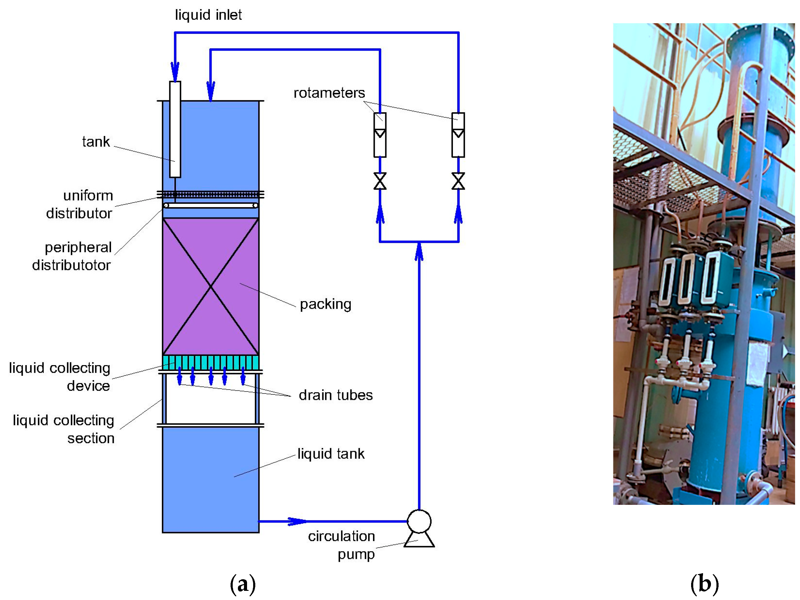
2. Materials and Methods
3. Results and Discussion
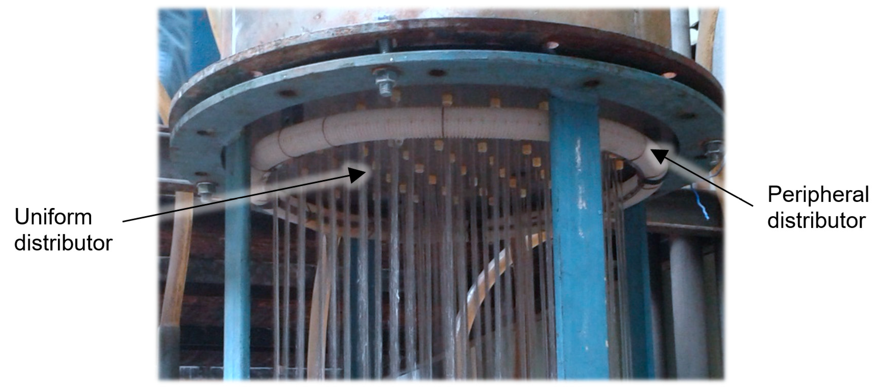
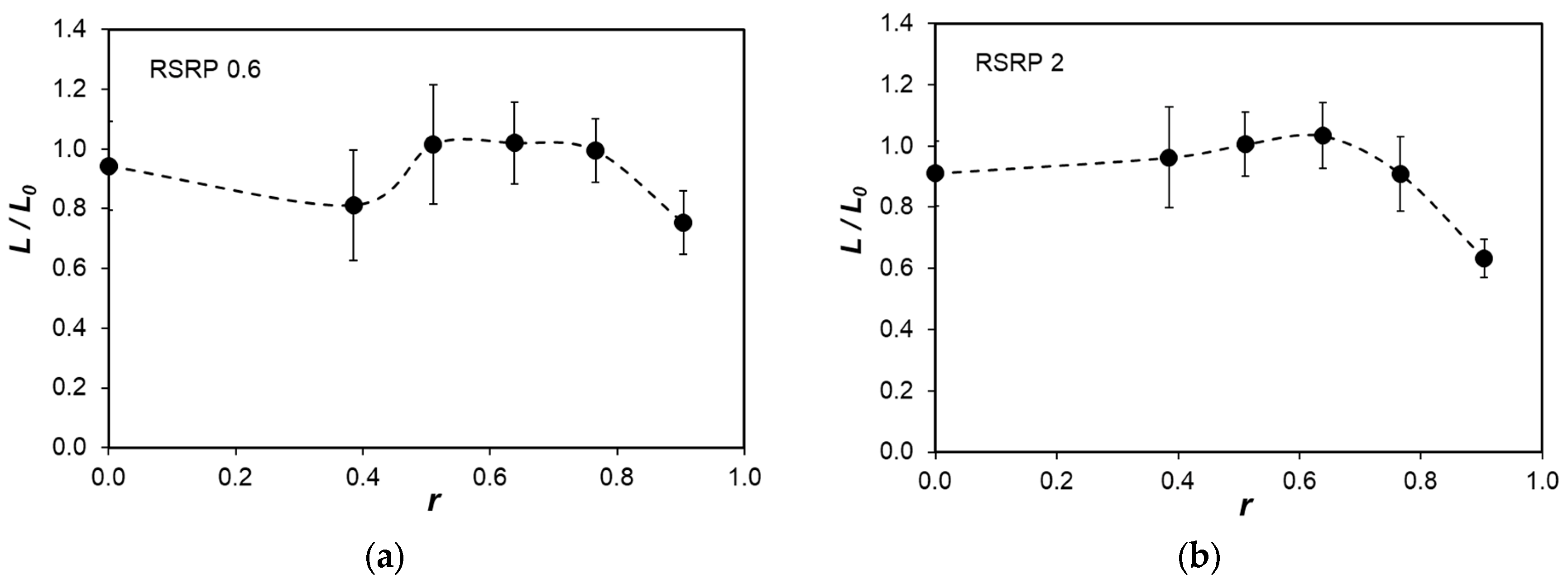
3.1. Uniform Initial Liquid Distribution
3.2. Peripheral Initial Liquid Distribution
3.3. Evaluation of the Liquid Radial Maldistribution
- 1.
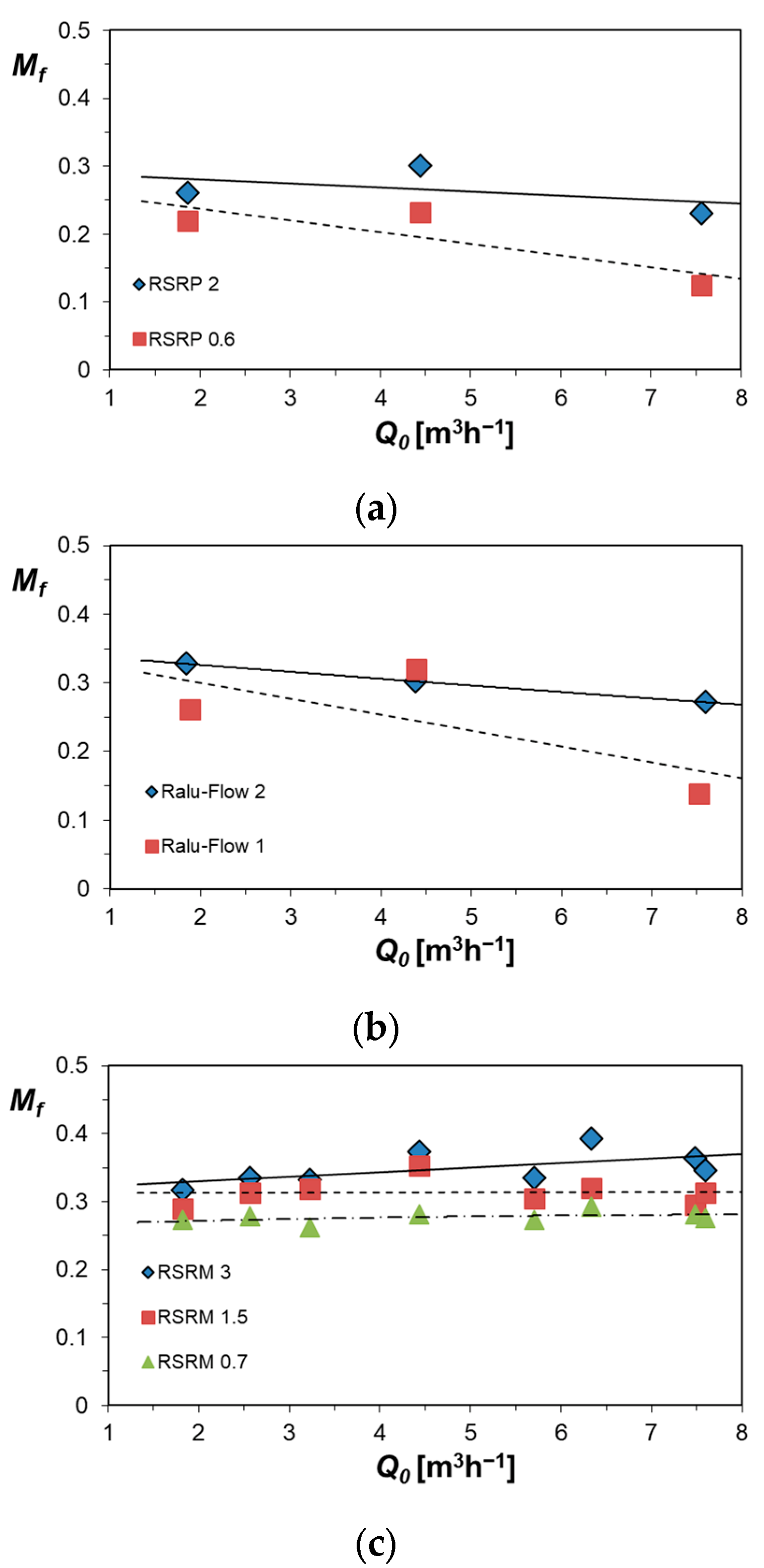
- The maldistribution factor depends strongly on the liquid load and decreases with the increase in liquid load at low gas loads up to the loading point. On the contrary, at high gas loads above the loading point, the maldistribution increases with the increase in liquid load.
- 2.
- The maldistribution factor is almost independent of the gas load up to the loading point and it sharply increases with the further increase in the gas load to a maximal value in flooding conditions.
- 3.
- Below the loading point, the maldistribution slightly increases with the increase in packing height; however, after a certain height (above 2.5 m), it becomes constant and the liquid distribution assumes an equilibrium state. At gas loads above the loading point, the influence of the gas load is much stronger than that of the bed height and the data at different heights almost coincide.
4. Conclusions
- 1.
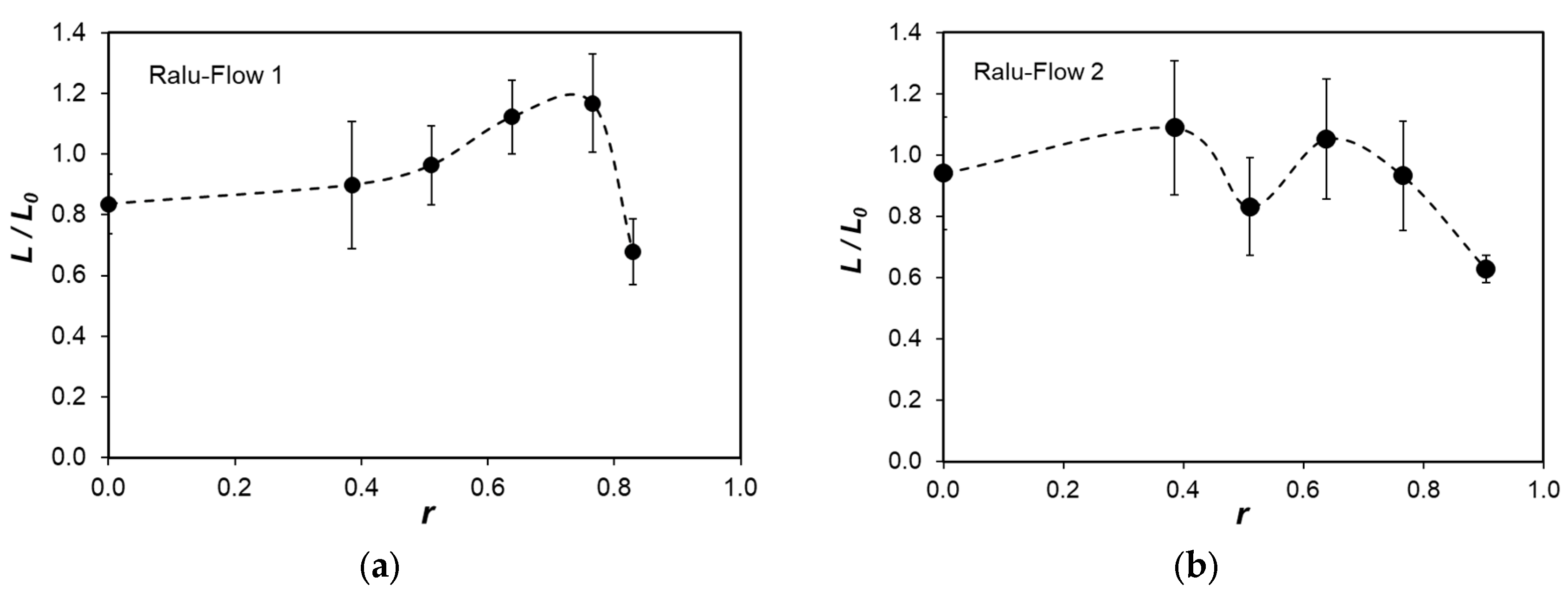
- In uniform initial irrigation, the liquid superficial velocity profiles in RSRP and RF are practically uniform in the column bulk and independent of the liquid load.
- 2.
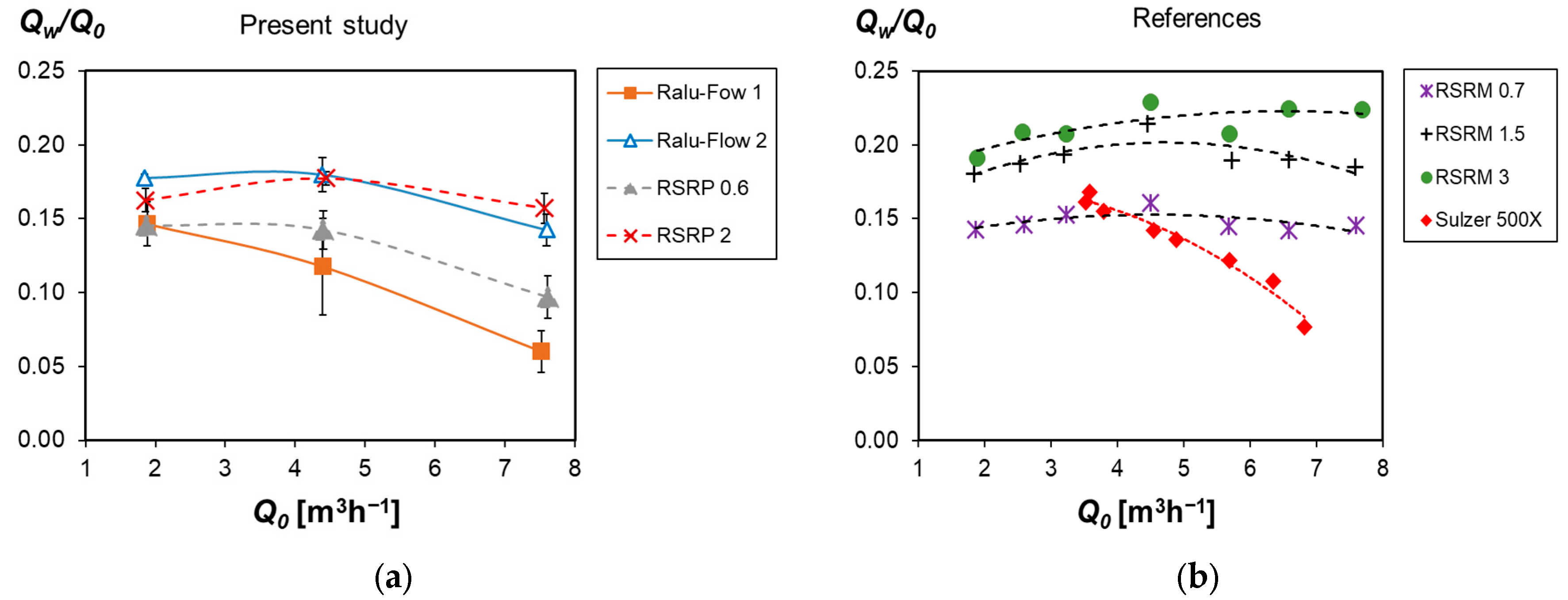
- The relative wall flow in uniform initial distribution increases with the increase in nominal packing size, which leads to a higher value of the maldistribution factor. The relative wall flow and, consequently, the maldistribution factor decrease with the increase in liquid load except for a packed bed with a small height, where a small wall flow increase is observed in some packings.
- 3.
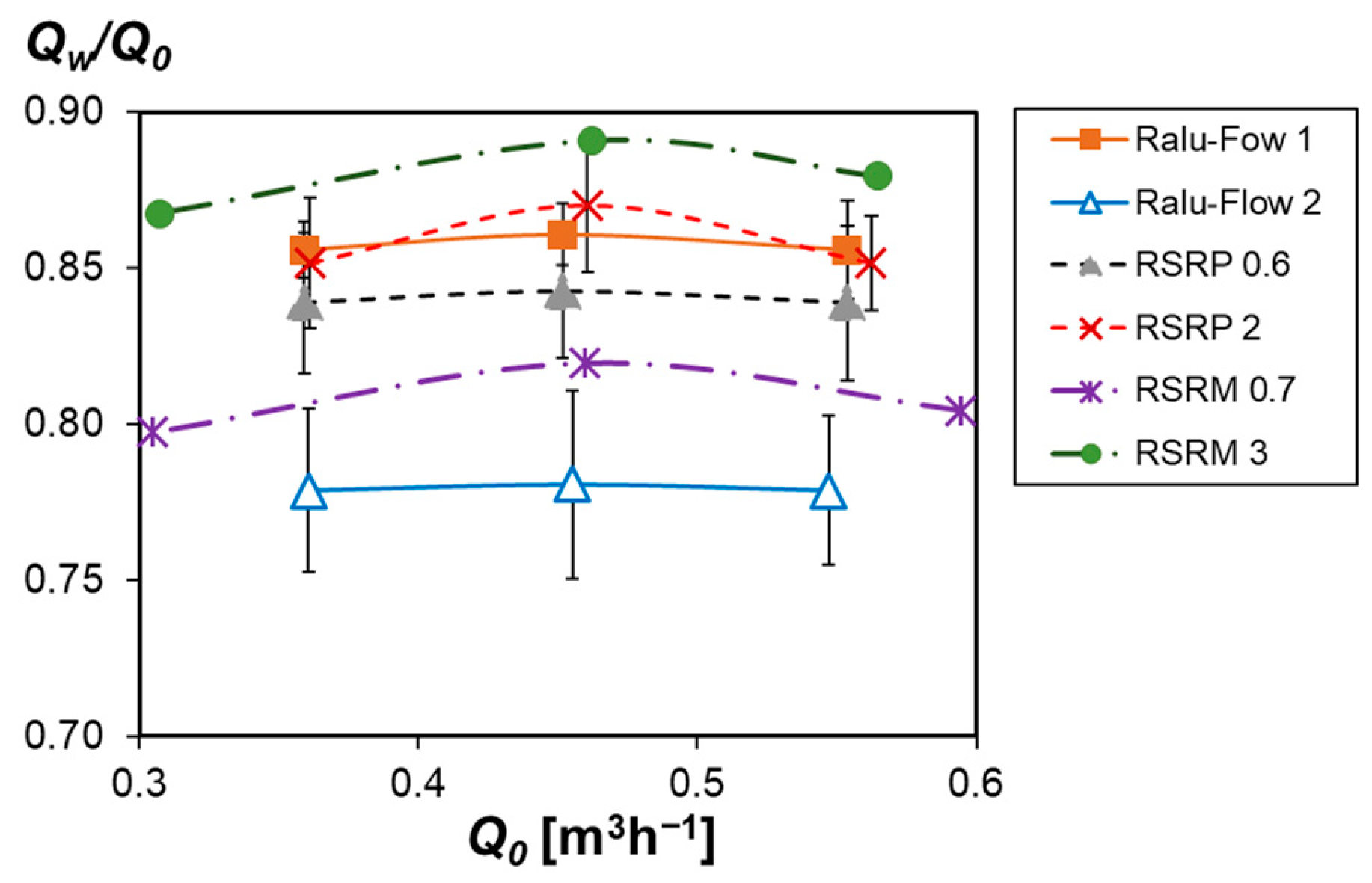
- The evaluation of the ability of the packings to return part of the wall flow in the column bulk in peripheral irrigation shows that the packings which retain more liquid in the wall flow are characterized by lower spreading capacity. The spreading capacity of the packing is independent of the liquid load and is evaluated by the spreading coefficients, calculated in point source initial distribution.
- 4.
- As expected, the large-scale liquid maldistribution in RSRP and RF is higher (Mf is two–three times higher) than in structured packings. However, there are operating conditions when Mf decreases close to the values of some structured packings.
Author Contributions
Funding
Data Availability Statement
Conflicts of Interest
Glossary
| D | column diameter [m] |
| Dr | liquid spreading coefficient [m] |
| F0 | cross-section area of the column [m2] |
| Fi | cross section area of the collection annulus i [m2] |
| Fv | gas/vapor capacity factor [Pa0.5] |
| h | axial coordinate [m] |
| H | height of the packing layer [m] |
| L0 | liquid load [m3m−2s−1] |
| Li | local liquid superficial velocity in a collection annulus i [m3m−2s−1] |
| Mf | liquid maldistribution factor [–] |
| Q0 | total liquid flow rate [m3h−1] |
| Qi | liquid flow rate in a collection annulus i [m3h−1] |
| dimensionless radial cooridante, r = R/R0 [–] | |
| R | radial coordinate [m] |
| R0 | column radius [m] |
| Ri | outer radius of a collection section [m] |
| Abbreviations | |
| CFD | Computational Fluid Dynamics |
| IMTP | Intalox Metal Tower Packing |
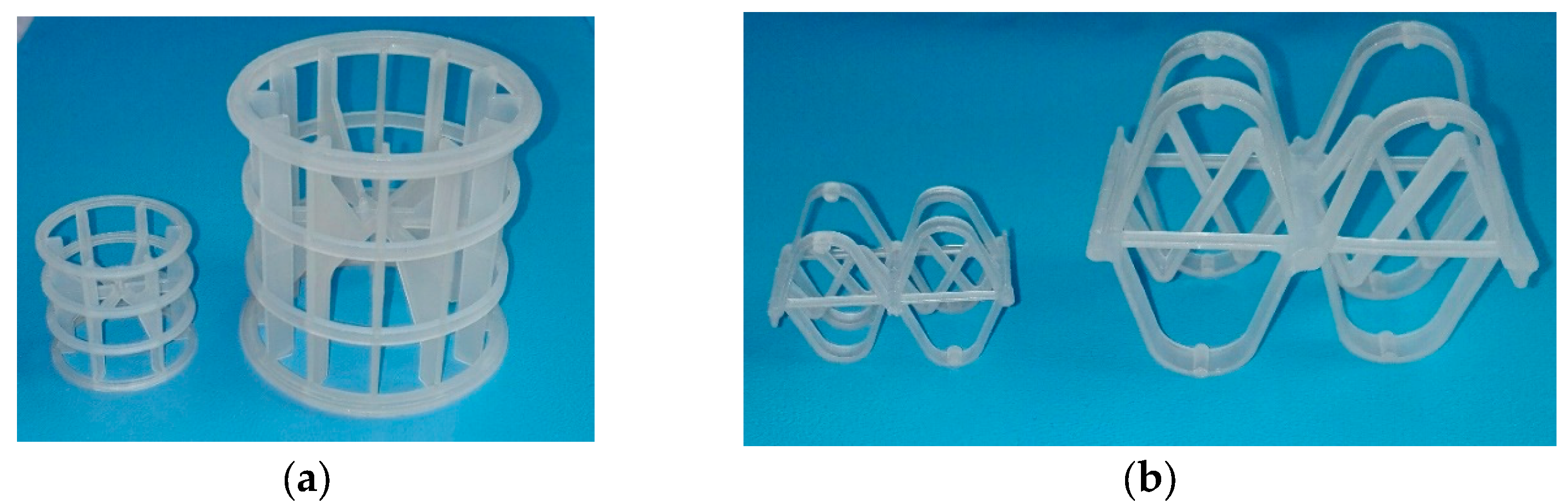
| RF | Ralu–Flow |
| RMSR | Rauschert Metal Saddle Ring |
| RSRM | metal Raschig Super-Ring |
| RSRP | plastic Raschig Super-Ring |
References
- Kolev, N. Packed Bed Columns: For Absorption, Desorption, Rectification and Direct Heat Transfer; Elsevier: Amsterdam, The Netherlands, 2006; p. 662. [Google Scholar]
- Darakchiev, R.; Darakchiev, S.; Dzhonova-Atanasova, D.; Nakov, S. Ceramic block packing of Honeycomb type for absorption processes and direct heat transfer. Chem. Eng. Sci. 2016, 155, 127–140. [Google Scholar] [CrossRef]
- Mackowiak, J. Model for the prediction of liquid phase mass transfer of random packed columns for gas–liquid systems. Chem. Eng. Res. Design 2011, 89, 1308–1320. [Google Scholar] [CrossRef]
- Schultes, M. Raschig Super-Ring. A New Fourth Generation Packing Offers New Advantages. Chem. Eng. Res. Des. 2003, 81, 48–57. [Google Scholar] [CrossRef] [Green Version]
- Billet, R.; Schultes, M. Prediction of mass transfer columns with dumped and arranged packings. Updated summary of the calculation method of Billet and Schultes. Chem. Eng. Res. Des. 1999, 77, 498–504. [Google Scholar] [CrossRef]
- Mackowiak, J. Fluid Dynamics of Packed Columns; Springer: Berlin/Heidelberg, Germany, 2010; p. 140. [Google Scholar]
- Marchot, P.; Toye, D.; Crine, M.; Pelsser, A.-M.; L’Homme, L. Investigation of liquid maldistribution in packed columns by x-ray tomography. Trans. IChemE 1999, 77, 511–518. [Google Scholar] [CrossRef]
- Hoek, P.J.; Wesselingh, J.A.; Zuiderweg, F.J. Small scale and large scale liquid maldistribution in packed columns. Chem. Eng. Res. Design 1986, 64, 431–449. [Google Scholar]
- Cihla, Z.; Schmidt, O. A study of the flow of liquid when freely trickling over the packing in a cylindrical tower. Collect. Czechoslov. Chem. Commun. 1957, 22, 896–907. [Google Scholar] [CrossRef]
- Staněk, V.; Kolář, V. Distribution of liquid over random packing. Collect. Czechoslov. Chem. Commun. 1965, 30, 1054–1059. [Google Scholar]
- Porter, E.; Templeman, J. Liquid flow in packed columns. Part III: Wall flow. Trans. Instn. Chem. Engrs. 1968, 46, T86–T94. [Google Scholar]
- Pavlenko, A.N.; Zhukov, V.E.; Sukhorukova, E.Y.; Dzhonova-Atanasova, D.B.; Stefanova, K.V. Experimental study of liquid flow maldistribution in Sulzer 500X structured packing and Raschig Super-Ring random packing. J. Eng. Thermophys. 2021, 30, 171–183. [Google Scholar] [CrossRef]
- Hanusch, F.; Rehfeldt, S.; Klein, H. Liquid maldistribution in random packed columns: Experimental investigation of influencing factors. Chem. Eng. Technol. 2018, 41, 2241–2249. [Google Scholar] [CrossRef]
- Dzhonova-Atanasova, D.; Kolev, N.; Nakov, S. Determination of liquid radial spreading coefficient of some highly effective packings. Chem. Eng. Technol. 2007, 30, 202–288. [Google Scholar] [CrossRef]
- Spiegel, L. The Maldistribution Story—An Industrial Perspective. Chem. Eng. Trans. 2018, 69, 715–720. [Google Scholar] [CrossRef]
- Zuiderweg, F.J.; Kunesh, J.G.; King, D.W. A model for the calculation of the effect of maldistribution on the efficiency of a packed column, Trans. IChemE 1993, 71, 38–44. [Google Scholar]
- Hanusch, F.; Künzler, M.; Renner, M.; Rehfeldt, S.; Klein, H. Liquid distributor design for random packed columns. Chem. Eng. Res. Design 2019, 147, 689–698. [Google Scholar] [CrossRef]
- Pavlenko, A.N.; Pecherkin, N.I.; Zhukov, V.E.; Meski, G.; Houghton, P. Overview of methods to control the liquid distribution in distillation columns with structured packing: Improving separation efficiency. Renew. Sustain. Energy Rev. 2020, 132, 110092. [Google Scholar] [CrossRef]
- Kouri, R.; Sohlo, J. Liquid and gas flow patterns in random packings. Chem. Eng. J. 1996, 61, 95–105. [Google Scholar] [CrossRef]
- Semkov, K.; Kolev, N.; Stanek, V. Theoretical and experimental investigation of the function of the wall flow deflecting ring. The determination of the optimum distance between deflecting rings. Collect. Czechoslov. Chem. Commun. 1987, 52, 2438–2446. [Google Scholar] [CrossRef]
- Schultes, M. Influence of Liquid Redistributors on the Mass-Transfer Efficiency of Packed Columns. Ind. Eng. Chem. Res. 2000, 39, 1381–1389. [Google Scholar] [CrossRef]
- Semkov, K.; Darakchiev, S. The influence of small scale maldistribution in the vapor phase on the efficiency of the rectification in packed columns. Bulg. Chem. Commun. 2010, 42, 194–204. [Google Scholar]
- Darakchiev, S.; Petrova, T.; Darakchiev, R. Gas distribution in packed-bed columns with IMTP-ring and Ralu-flow. Chem. Biochem. Eng. Q. 2005, 19, 147–152. [Google Scholar]
- Petrova, T.; Vaklieva-Bancheva, N.; Darakchiev, S.; Popov, R. Quantitative estimates of gas maldistribution and methods for their localization in absorption columns. Clean Technol. Environ. Policy 2014, 16, 1381–1392. [Google Scholar] [CrossRef]
- Lockett, M.J.; Billingham, J.F. The Effect of Maldistribution on Separation in Packed Distillation Columns. Trans. IChemE 2003, 81, 131–135. [Google Scholar] [CrossRef] [Green Version]
- Hanley, B. The influence of flow maldistribution on the performance of columns containing random packings: A model study for constant relative volatility and total reflux. Separ. Purific. Tech. 1999, 16, 7–23. [Google Scholar] [CrossRef]
- Yin, F. Liquid Maldistribution and Mass Transfer Efficiency in Randomly Packed Distillation Columns. Ph.D. Thesis, University of Alberta, Edmonton, AB, Canada, 1999. [Google Scholar]
- Boyadjiev, B.; Boyadjiev, C.; Popova-Krumova, P. Convective type models of co-current absorption processes in column apparatuses. Bulg. Chem. Commun. 2020, 52, 74–79. [Google Scholar]
- Boyadjiev, C.; Doichinova, M.; Boyadjiev, B.; Popova-Krumova, P. Modeling of Column Apparatus Processes, 2nd ed.; Springer: Berlin/Heidelberg, Germany, 2018. [Google Scholar]
- Chr, B.; Doichinova, M.; Boyadjiev, B.; Popova-Krumova, P. Transfer processes in industrial column apparatuses. Math. Model. 2017, 1, 23–27. [Google Scholar]
- Boyadjiev, C.; Boyadjiev, B.; Popova-Krumova, P.; Doichinova, M. An innovative approach for adsorption column modeling. Chem. Eng. Technol. 2015, 38, 675–682. [Google Scholar] [CrossRef]
- Dang-Vu, T.; Doan, H.D.; Lohi, A.; Zhu, Y. A new liquid distribution factor and local mass transfer coefficient in a random packed bed. Chem. Eng. J. 2006, 123, 81–91. [Google Scholar] [CrossRef]
- Winkler, T.; Klein, H.; Rehfeldt, S. Experimental investigation of liquid maldistribution in random packed columns using temperature measurements. Chem. Eng. Sci. 2022, 249, 117350. [Google Scholar] [CrossRef]
- Hanusch, F.; Engel, V.; Kender, R.; Rehfeldt, S.; Klein, H. Development and application of the TUM-WelChem cell model for prediction of liquid distribution in random packed columns. Chem. Eng. Trans. 2018, 69, 739–744. [Google Scholar]
- Hanusch, F.; Kender, R.; Engel, V.; Rehfeldt, S.; Klein, H. TUM–WelChem cell model for the prediction of liquid distribution in random packed columns. AIChE J. 2019, 65, e16598. [Google Scholar] [CrossRef]
- Boyadjiev, C.; Dzhonova-Atanasova, D.; Popova-Krumova, P.; Stefanova, K.; Pavlenko, A.; Zhukov, V.; Slesareva, E. Liquid wall flow in counter-current column apparatuses for absorption processes with random packings. Bulg. Chem. Commun. 2020, 52, 74–79. [Google Scholar]
- Mackowiak, J. Pressure drop in irrigated packed columns. Chem. Eng. Process. 1991, 29, 93–105. [Google Scholar] [CrossRef]
- Nakov, S.T.; Dzhonova-Atanasova, D.B.; Kolev, N.N. Pressure drop of high performance random Intalox Metal Tower Packing. Bulg. Chem. Commun. 2012, 44, 283–288. [Google Scholar]
- Stanek, V.; Kolar, V. Distribution of liquid over a random packig. VII. The dependence of distribution parameters on the column and packing diameter. Collect. Czechoslov. Chem. Commun. 1973, 38, 1012–1026. [Google Scholar] [CrossRef]
- Petrova, T.S.; Dzhonova-Atanasova, D.B. Simulation of the liquid distribution in the wall zone of a packed column: Case study. Bulg. Chem. Commun. 2019, 51, 91–98. [Google Scholar]
- Dzhonova-Atanasova, D.; Petrova, T.; Semkov, K.; Darakchiev, S.; Stefanova, K.; Nakov, S.; Popov, R. Experimental investigation of liquid distribution in open structure random packings as a basis for model refinement. Chem. Eng. Trans. 2018, 70, 2077–2082. [Google Scholar] [CrossRef]
- Petrova, T.; Semkov, K.; Dzhonova-Atanasova, D. Modeling of liquid distribution in a packed column with open-structure random packings. Chem. Eng. Trans. 2018, 70, 1051–1056. [Google Scholar] [CrossRef]


| Collection Section | Ri [m] | Fi [m2] | |
|---|---|---|---|
| 1 | 0.076 | 0.0181 | 10.5 |
| 2 | 0.105 | 0.0165 | 9.5 |
| 3 | 0.135 | 0.0226 | 13 |
| 4 | 0.165 | 0.0283 | 16.3 |
| 5 | 0.195 | 0.0339 | 19.6 |
| 6 | 0.230 | 0.0467 | 26.9 |
| 7 | 0.235 | 0.0730 | 4.2 |
Disclaimer/Publisher’s Note: The statements, opinions and data contained in all publications are solely those of the individual author(s) and contributor(s) and not of MDPI and/or the editor(s). MDPI and/or the editor(s) disclaim responsibility for any injury to people or property resulting from any ideas, methods, instructions or products referred to in the content. |
© 2023 by the authors. Licensee MDPI, Basel, Switzerland. This article is an open access article distributed under the terms and conditions of the Creative Commons Attribution (CC BY) license (https://creativecommons.org/licenses/by/4.0/).
Share and Cite
Dzhonova-Atanasova, D.; Stefanova, K.; Nakov, S. On Liquid Flow Maldistribution through Investigation of Random Open-Structure Packings. Designs 2023, 7, 47. https://doi.org/10.3390/designs7020047
Dzhonova-Atanasova D, Stefanova K, Nakov S. On Liquid Flow Maldistribution through Investigation of Random Open-Structure Packings. Designs. 2023; 7(2):47. https://doi.org/10.3390/designs7020047
Chicago/Turabian StyleDzhonova-Atanasova, Daniela, Konstantina Stefanova, and Svetoslav Nakov. 2023. "On Liquid Flow Maldistribution through Investigation of Random Open-Structure Packings" Designs 7, no. 2: 47. https://doi.org/10.3390/designs7020047