
A Numerical Thermal Analysis of a Battery Pack in an Electric Motorbike Application


 ,
,  ,
, 

Abstract
:1. Introduction
2. Methodology and Simulation
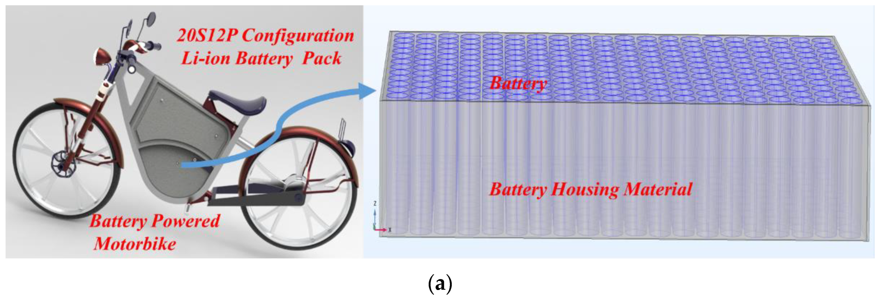
2.1. Battery Pack Configuration
2.2. Battery Thermal Model
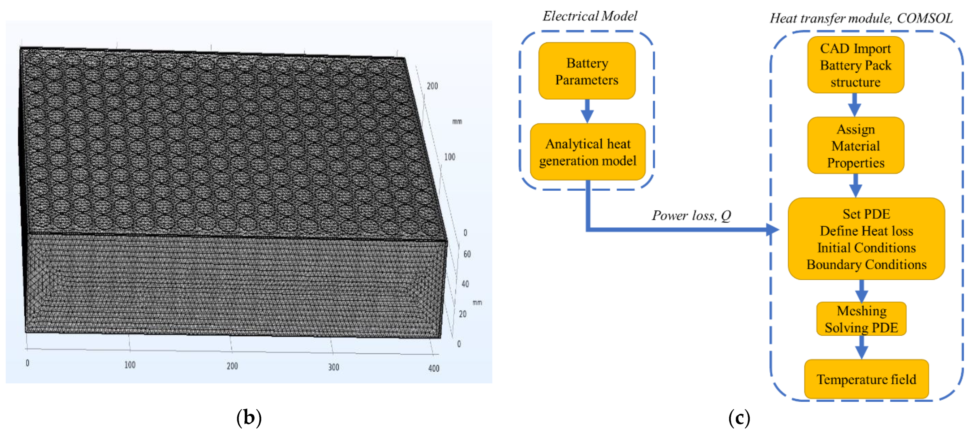
2.3. FEA Model Development
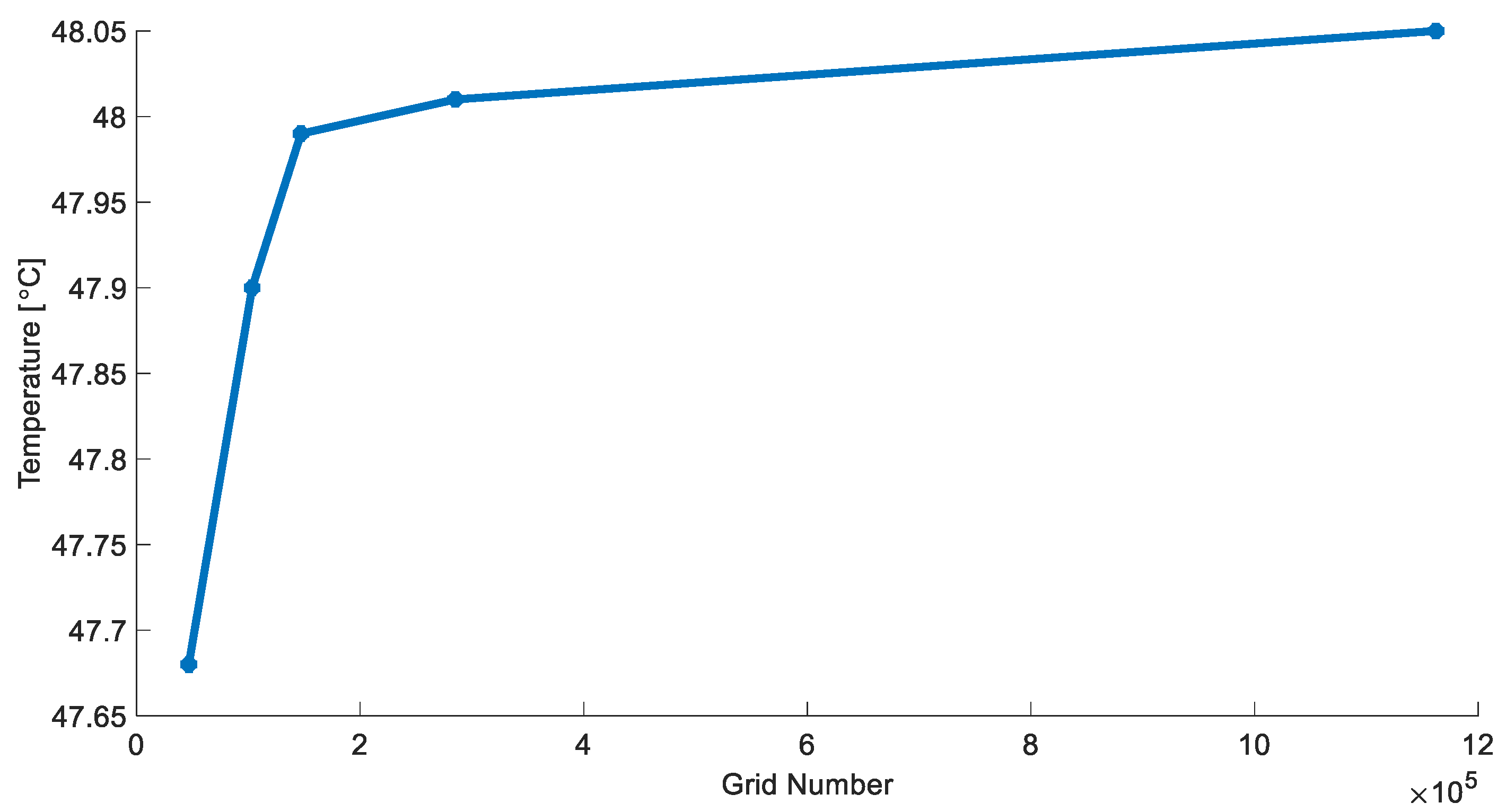
2.4. Mesh Independence Test
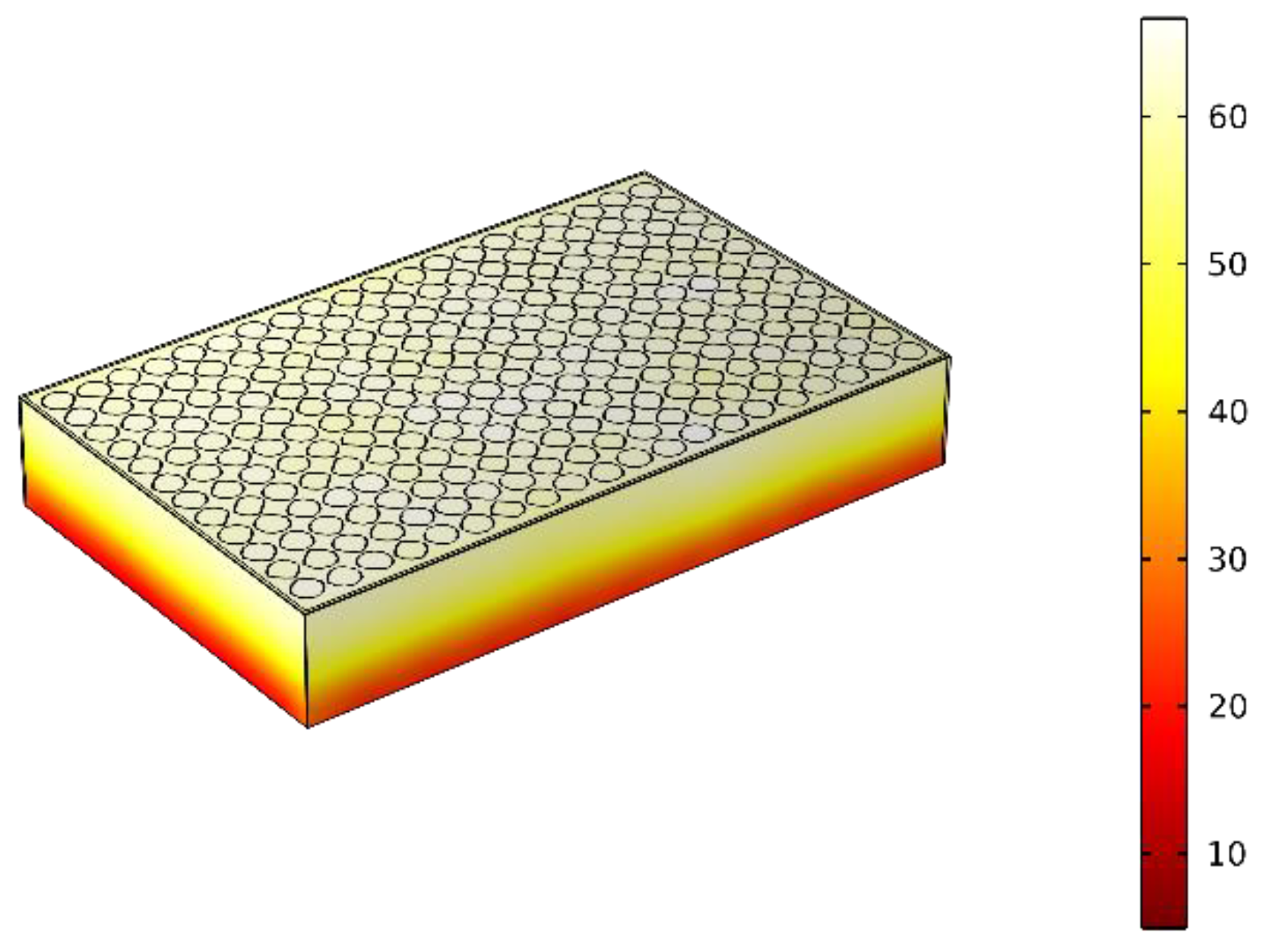
3. Results and Discussion
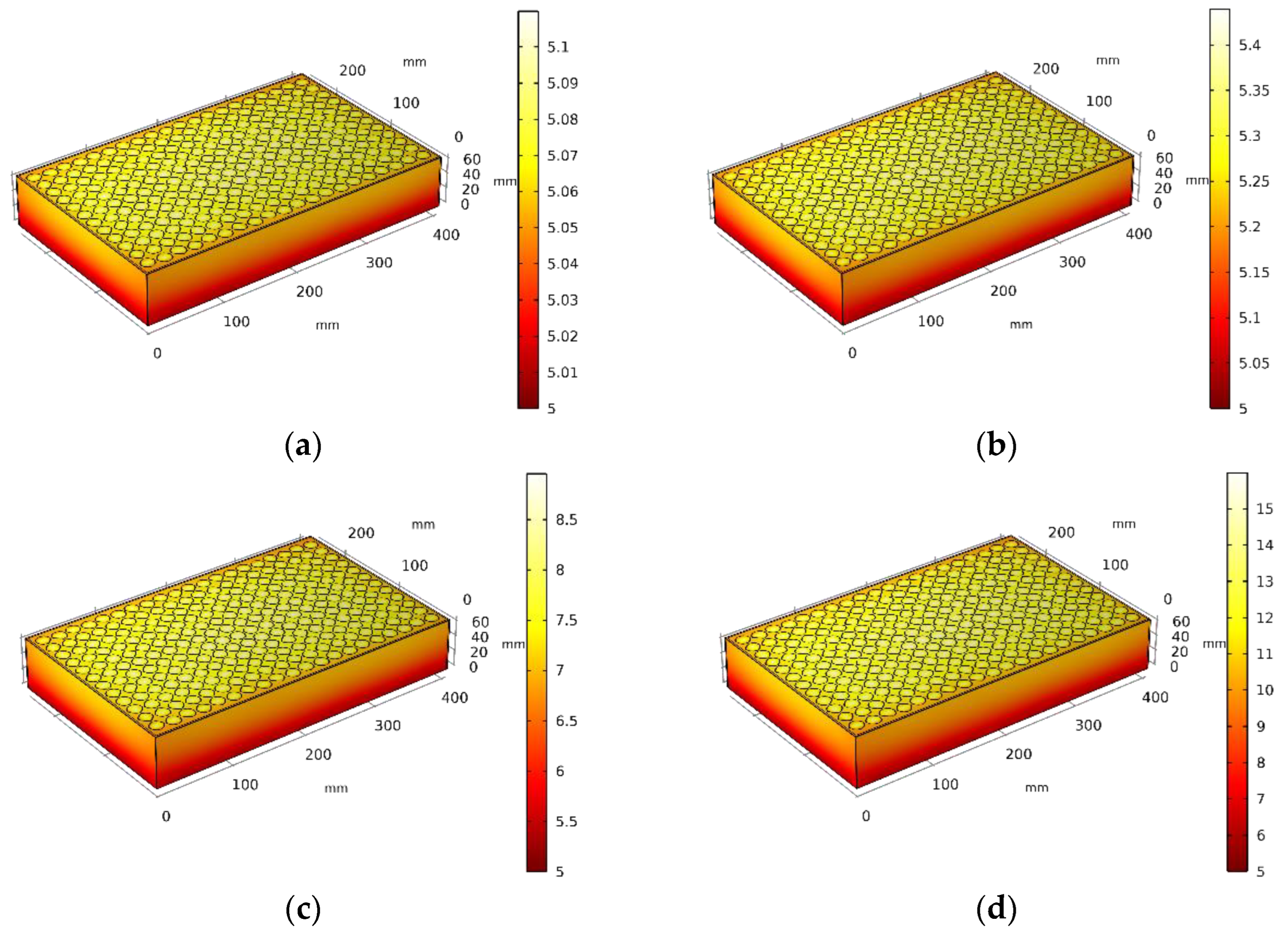
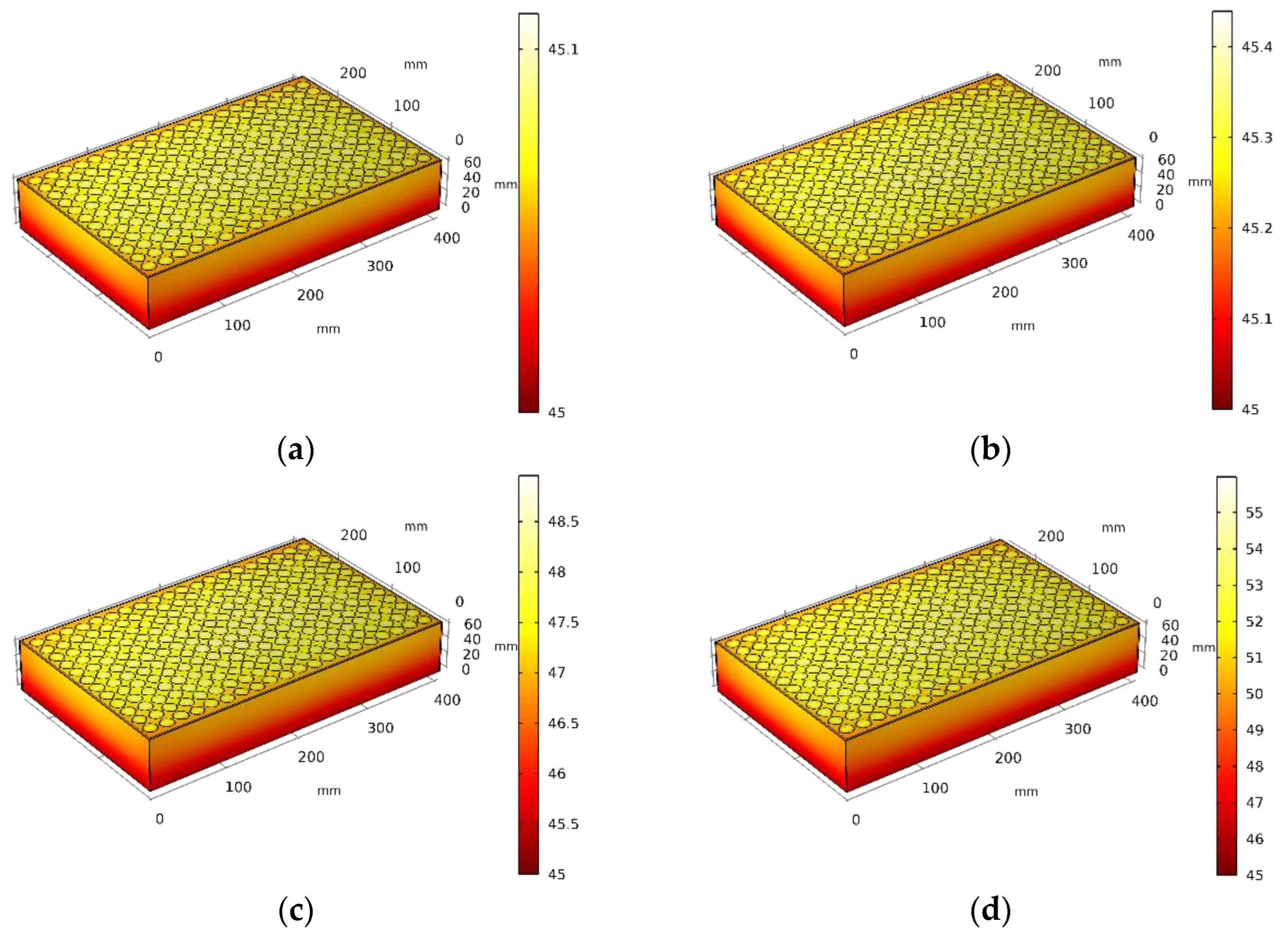
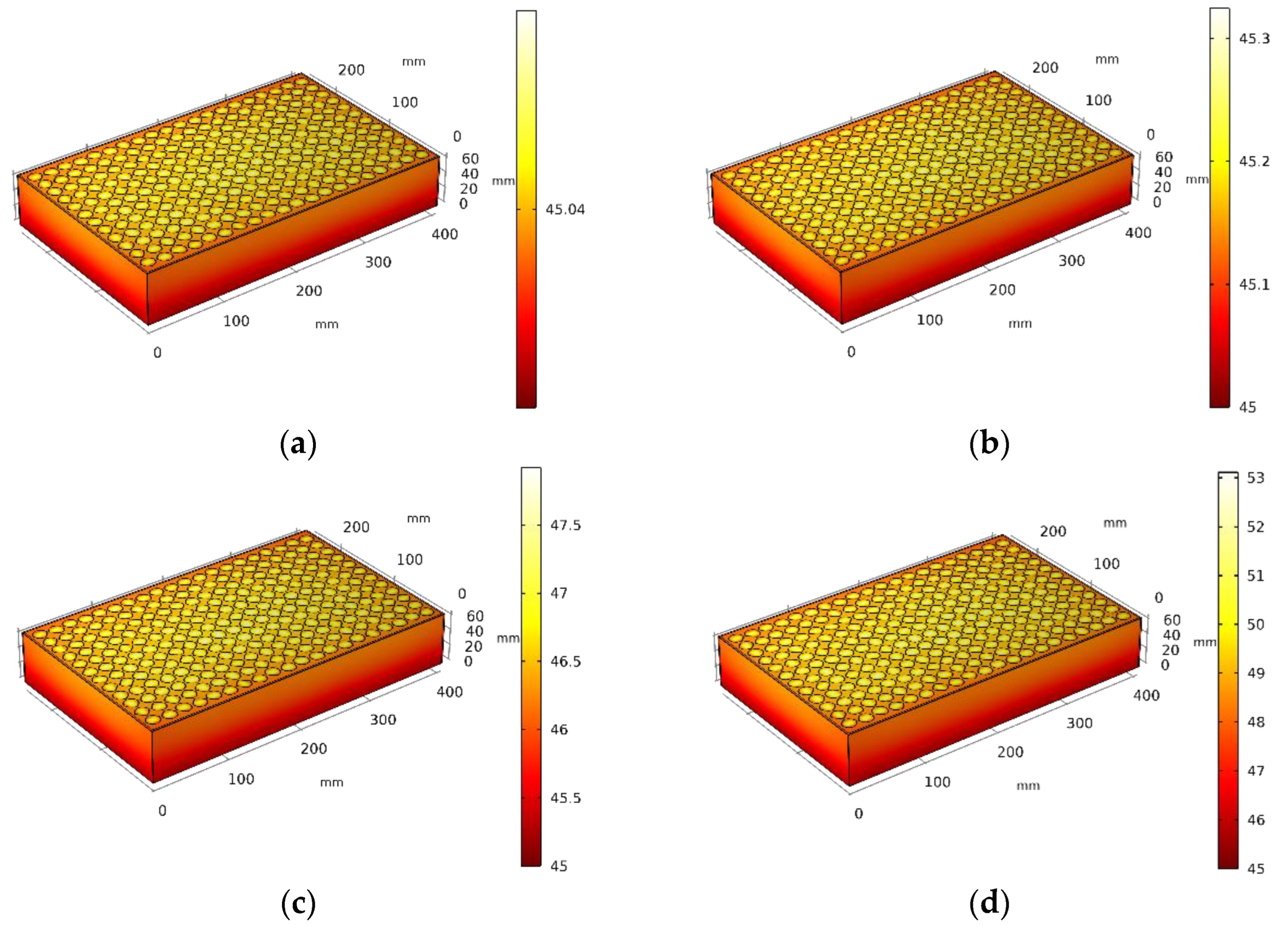
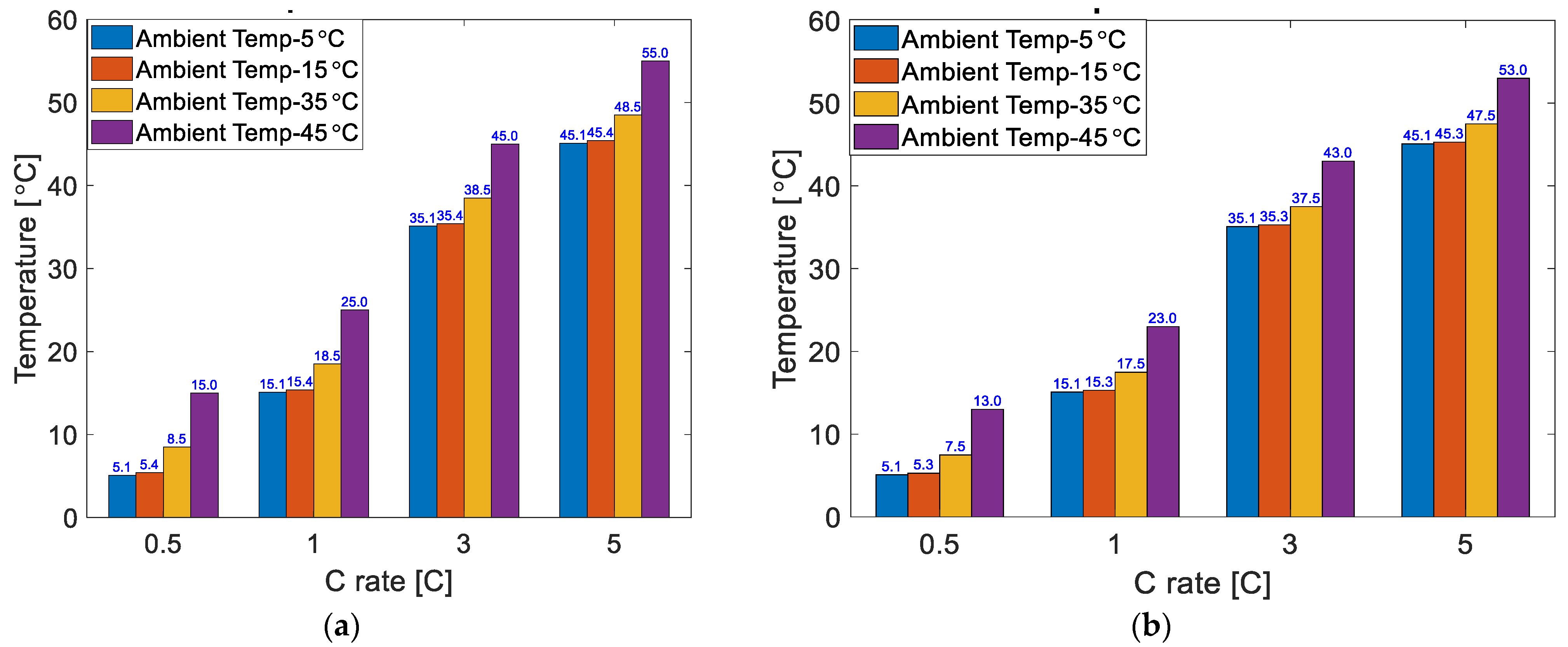
3.1. Effect of Ambient Temperature
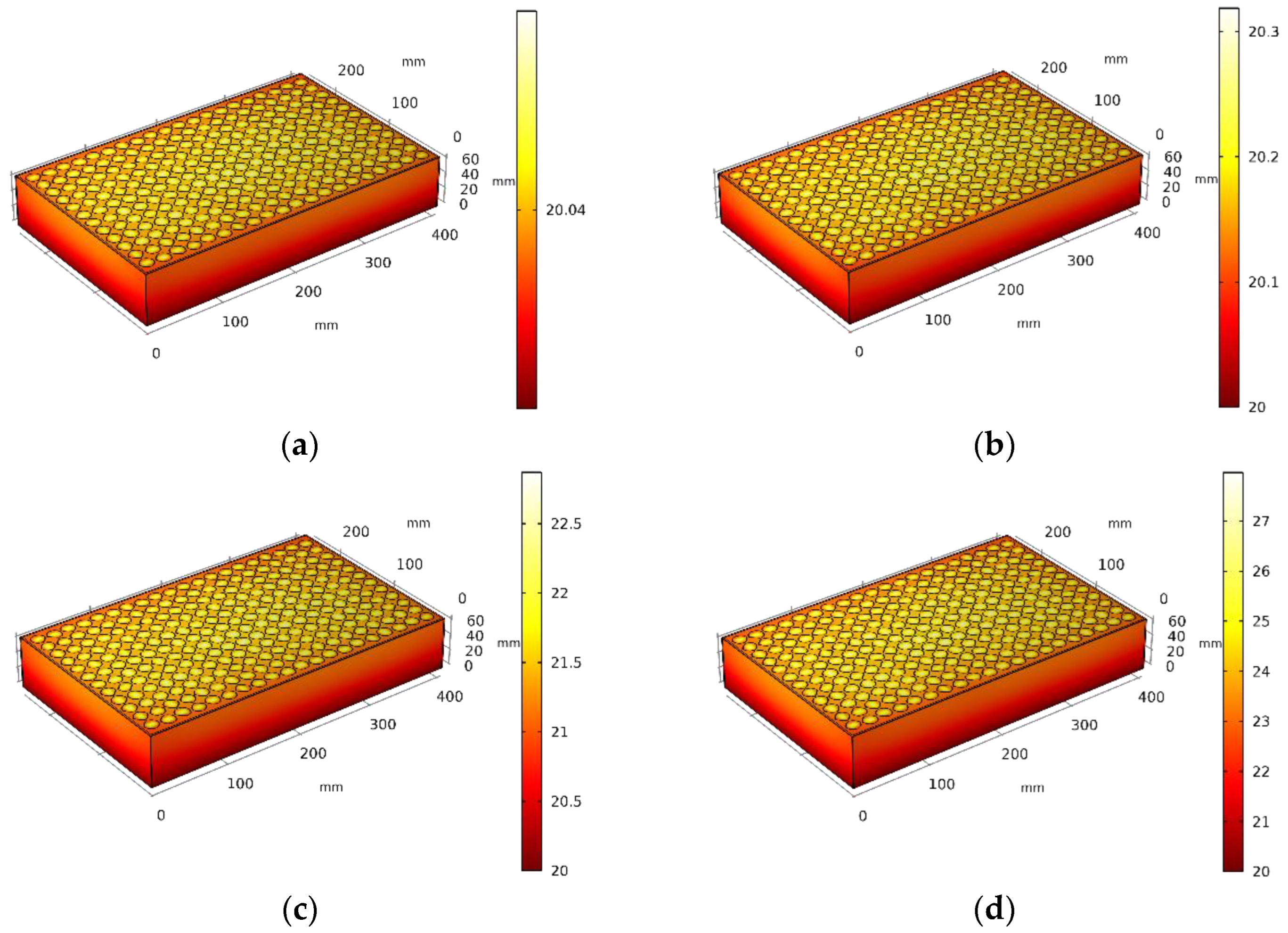
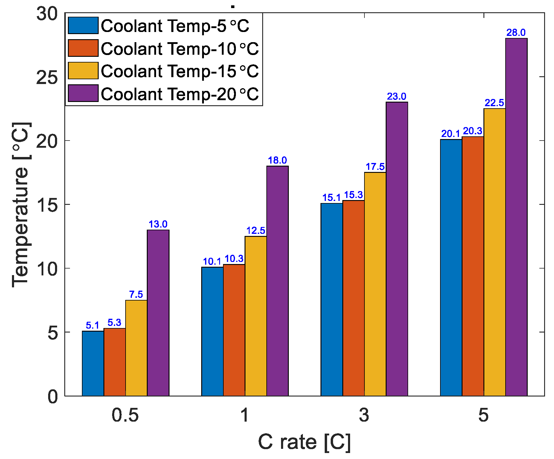
3.2. Effect of Coolant Temperature
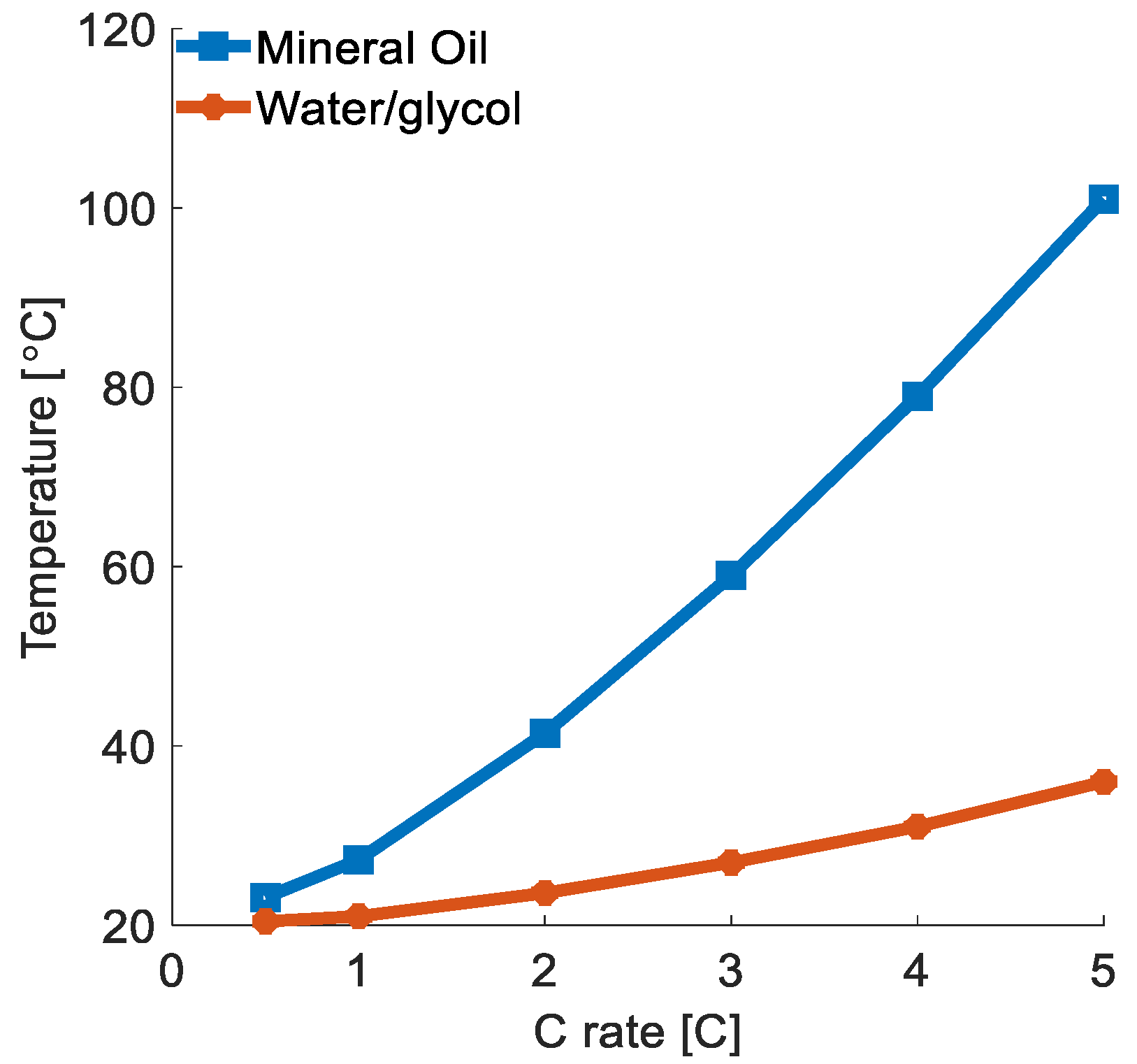
3.3. Effect of Coolant Types
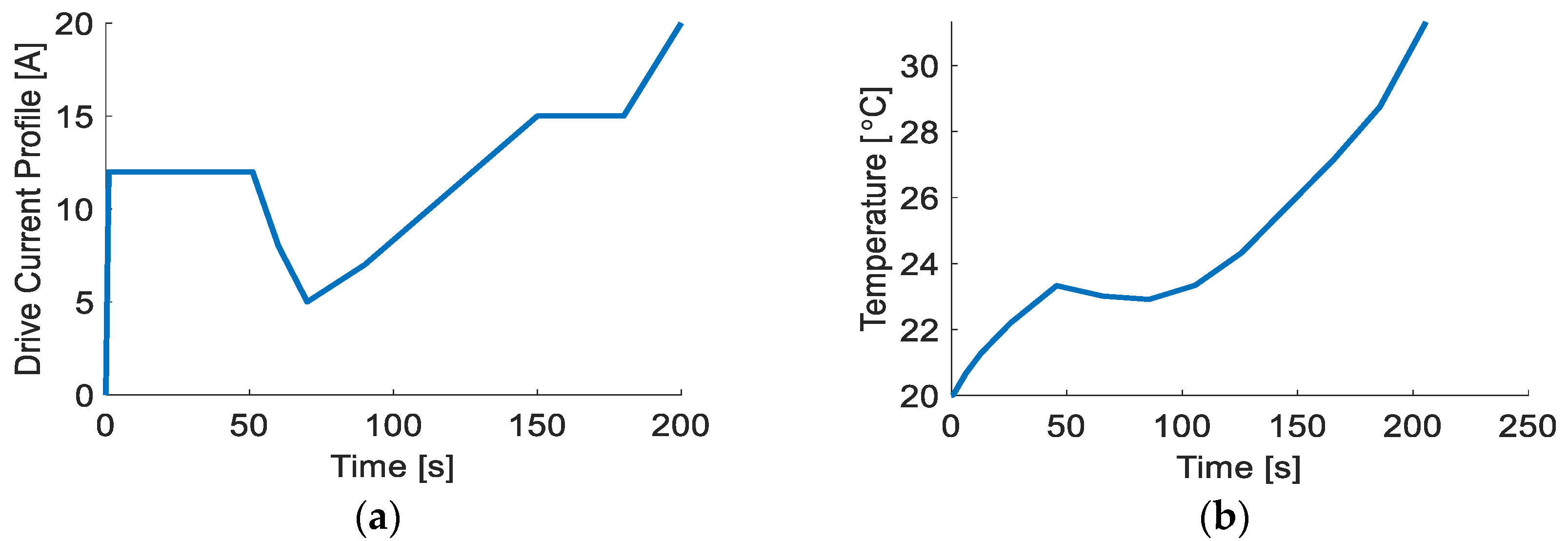
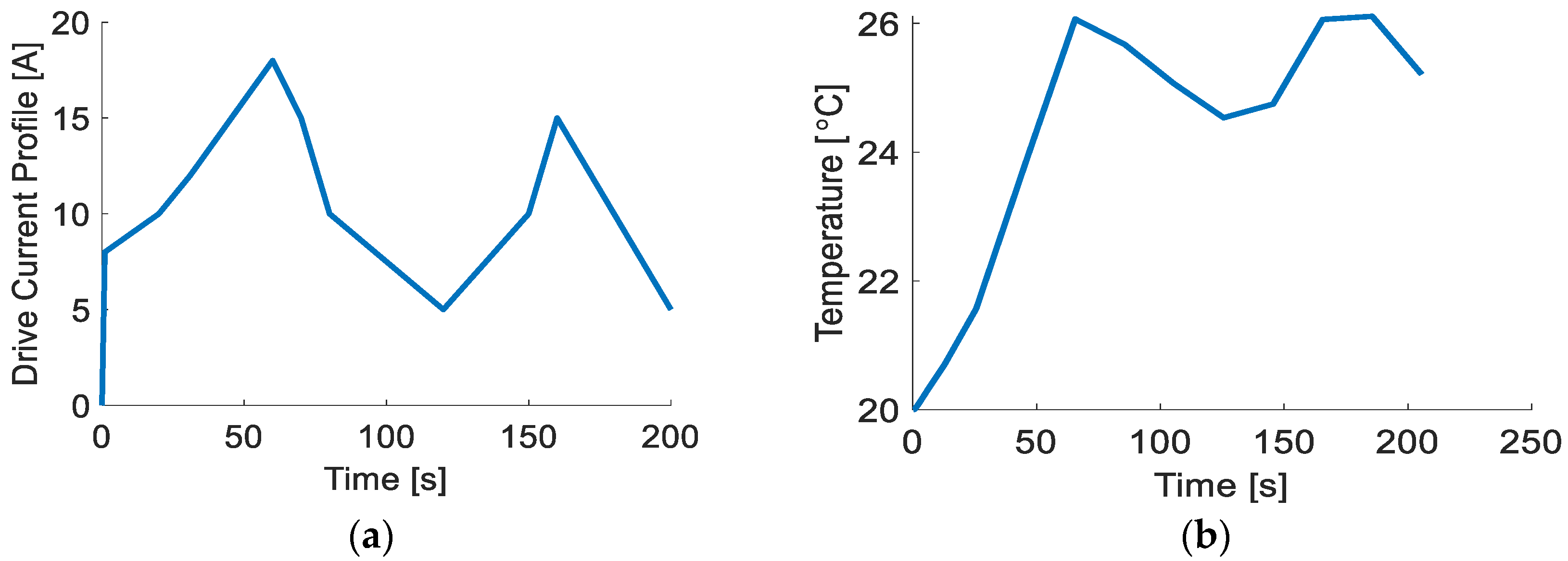
3.4. Validation of Thermal Performance Analysis under Custom Drive Profile
3.5. Uncertainity Analysis
3.6. General Discussion
4. Conclusions
Author Contributions
Funding
Institutional Review Board Statement
Informed Consent Statement
Data Availability Statement
Acknowledgments
Conflicts of Interest
References
- Zhang, J.; Zhang, L.; Sun, F.; Wang, Z. An overview on thermal safety issues of lithium-ion batteries for electric vehicle application. IEEE Access 2018, 6, 23848–23863. [Google Scholar] [CrossRef]
- Kuang, X.; Li, K.; Xie, Y.; Wu, C.; Wang, P.; Wang, X.; Fu, C. Research on control strategy for a battery thermal management system for electric vehicles based on sec-ondary loop cooling. IEEE Access 2020, 8, 73475–73493. [Google Scholar] [CrossRef]
- Sundin, D.W.; Sponholtz, S. Thermal Management of Li-Ion Batteries with Single-Phase Liquid Immersion Cooling. IEEE Open J. Veh. Technol. 2020, 1, 82–92. [Google Scholar] [CrossRef]
- Hu, Z.; He, X.; Restuccia, F.; Yuan, H.; Rein, G. Numerical study of scale effects on self-heating ignition of lithium-ion batteries stored in boxes, shelves and racks. Appl. Therm. Eng. 2021, 190, 116780. [Google Scholar] [CrossRef]
- Behi, H.; Karimi, D.; Jaguemont, J.; Gandoman, F.H.; Kalogiannis, T.; Berecibar, M.; Van Mierlo, J. Novel thermal management methods to improve the performance of the Li-ion batteries in high discharge current applications. Energy 2021, 224, 120165. [Google Scholar] [CrossRef]
- Li, Y.; Yang, J.; Song, J. Design principles and energy system scale analysis technologies of new lithium-ion and alumi-num-ion batteries for sustainable energy electric vehicles. Renew. Sustain. Energy Rev. 2017, 71, 645–651. [Google Scholar] [CrossRef]
- Wang, Q.; Sun, Q.; Ping, P.; Zhao, X.; Sun, J.; Lin, Z. Heat transfer in the dynamic cycling of lithium–titanate batteries. Int. J. Heat Mass Transf. 2016, 93, 896–905. [Google Scholar] [CrossRef]
- Ge, H.; Huang, J.; Zhang, J.; Li, Z. Temperature-adaptive alternating current preheating of lithium-ion batteries with lithium deposition prevention. J. Electrochem. Soc. 2015, 163, A290. [Google Scholar] [CrossRef]
- Liang, J.; Gan, Y.; Li, Y. Investigation on the thermal performance of a battery thermal management system using heat pipe under different ambient temperatures. Energy Convers. Manag. 2018, 155, 1–9. [Google Scholar] [CrossRef]
- Vetter, J.; Novák, P.; Wagner, M.R.; Veit, C.; Möller, K.-C.; Besenhard, J.O.; Winter, M.; Wohlfahrt-Mehrens, M.; Vogler, C.; Hammouche, A. Ageing mechanisms in lithium-ion batteries. J. Power Sources 2005, 147, 269–281. [Google Scholar] [CrossRef]
- Abraham, D.P.; Liu, J.; Chen, C.; Hyung, Y.; Stoll, M.; Elsen, N.; MacLaren, S.; Twesten, R.; Haasch, R.; Sammann, E.; et al. Diagnosis of power fade mechanisms in high-power lithium-ion cells. J. Power Sources 2003, 119, 511–516. [Google Scholar] [CrossRef]
- Spotnitz, R.; Franklin, J. Abuse behavior of high-power, lithium-ion cells. J. Power Sources 2003, 113, 81–100. [Google Scholar] [CrossRef]
- Spotnitz, R.M.; Weaver, J.; Yeduvaka, G.; Doughty, D.H.; Roth, E.P. Simulation of abuse tolerance of lithium-ion bat-tery packs. J. Power Sources 2007, 163, 1080–1086. [Google Scholar] [CrossRef]
- Bandhauer, T.M.; Garimella, S.; Fuller, T.F. A critical review of thermal issues in lithium-ion batteries. J. Electrochem. Soc. 2011, 158, R1. [Google Scholar] [CrossRef]
- Greco, A.; Jiang, X.; Cao, D. An investigation of lithium-ion battery thermal management using paraffin/porous-graphite-matrix composite. J. Power Sources 2015, 278, 50–68. [Google Scholar] [CrossRef]
- Ni, P.; Wang, X. Temperature field and temperature difference of a battery package for a hybrid car. Case Stud. Therm. Eng. 2020, 20, 100646. [Google Scholar] [CrossRef]
- Behi, H.; Karimi, D.; Jaguemont, J.; Gandoman, F.H.; Khaleghi, S.; Van Mierlo, J.; Berecibar, M. Aluminum heat sink assisted air-cooling thermal management system for high current applications in electric vehicles. In Proceedings of the 2020 AEIT International Conference of Electrical and Electronic Technologies for Automotive (AEIT AUTOMOTIVE), Turin, Italy, 18–20 November 2020; pp. 1–6. [Google Scholar]
- Akbarzadeh, M.; Kalogiannis, T.; Jaguemont, J.; Jin, L.; Behi, H.; Karimi, D.; Berecibar, M. A comparative study between air cooling and liquid cooling thermal management systems for a high-energy lithium-ion battery module. Appl. Therm. Eng. 2021, 198, 117503. [Google Scholar] [CrossRef]
- Chen, F.; Huang, R.; Wang, C.; Yu, X.; Liu, H.; Wu, Q.; Bhagat, R. Air and PCM cooling for battery thermal management considering battery cycle life. Appl. Therm. Eng. 2020, 173, 115154. [Google Scholar] [CrossRef]
- Lu, M.; Zhang, X.; Ji, J.; Xu, X.; Zhang, Y. Research progress on power battery cooling technology for electric vehicles. J. Energy Storage 2020, 27, 101155. [Google Scholar] [CrossRef]
- Karimi, D.; Khaleghi, S.; Behi, H.; Beheshti, H.; Hosen, M.S.; Akbarzadeh, M.; Berecibar, M. Lithium-ion capacitor lifetime extension through an optimal thermal management system for smart grid applications. Energies 2021, 14, 2907. [Google Scholar] [CrossRef]
- Yu, G.; Zhang, X.; Wang, C.; Zhang, W.; Yang, C. Convective dimensionless method for measurement of heat genera-tion in a lithium thionyl chloride battery. J. Electrochem. Soc. 2013, 160, A2027. [Google Scholar] [CrossRef]
- Meng, F.; Chen, L.; Xie, Z. Numerical simulations and analyses on thermal characteristics of 18650 lithium-ion batteries with natural cooling conditions. Int. J. Energy Environ. 2017, 8, 43. [Google Scholar]
- Wang, D.; Bao, Y.; Shi, J. Online lithium-ion battery internal resistance measurement application in state-of-charge es-timation using the extended kalman filter. Energies 2017, 10, 1284. [Google Scholar] [CrossRef] [Green Version]
- LITHIUM-ION/NNP + HRL Technology. Available online: https://www.imrbatteries.com/content/panasonic_ncr18650b-2.pdf (accessed on 20 May 2022).
- Yang, N.; Zhang, X.; Li, G.; Hua, D. Assessment of the forced air-cooling performance for cylindrical lithium-ion bat-tery packs: A comparative analysis between aligned and staggered cell arrangements. Appl. Therm. Eng. 2015, 80, 55–65. [Google Scholar] [CrossRef]
- Rao, Z.; Qian, Z.; Kuang, Y.; Li, Y. Thermal performance of liquid cooling based thermal management system for cylin-drical lithium-ion battery module with variable contact surface. Appl. Therm. Eng. 2017, 123, 1514–1522. [Google Scholar] [CrossRef]
- Panchal, S.; Khasow, R.; Dincer, I.; Agelin-Chaab, M.; Fraser, R.; Fowler, M. Thermal design and simulation of mini-channel cold plate for water cooled large sized prismatic lithium-ion battery. Appl. Therm. Eng. 2017, 122, 80–90. [Google Scholar] [CrossRef]
- Kim, G.-H.; Pesaran, A. Battery thermal management design modeling. World Electr. Veh. J. 2007, 1, 126–133. [Google Scholar] [CrossRef] [Green Version]
- Bergman, T.L.; Incropera, F.P.; DeWitt, D.P.; Lavine, A.S. Fundamentals of Heat and Mass Transfer; John Wiley & Sons: Hoboken, NJ, USA, 2011. [Google Scholar]


| Battery Specifications | Values |
|---|---|
| Diameter (mm) | 18 |
| Height (mm) | 65 |
| Weight (g) | 45 |
| Chemistry | Nickel/Cobalt/Rechargeable |
| Maximum Charging Voltage | 4.2 |
| Nominal Voltage (V) | 3.7 |
| Minimum Cut-off Voltage (V) | 2.5 |
| Maximum Capacity (mAh) | 3350 |
| Nominal Capacity (mAh) | 3200 |
| Internal Resistance (mΩ) | 38 |
| Battery Pack Configuration | 20S12P |
| Working temperature range (°C) | Charge: 0 to +45 Discharge: −20 to +60 |
| Material | Density | Specific Heat | Thermal Conductivity |
|---|---|---|---|
| Battery | 2500 | 1200 | 4 |
| Al | 2719 | 871 | 202 |
| Cu | 8960 | 385 | 400 |
| Ambient Temperature (°C) | Al Housing, Predicted Temperature (°C) at Different Discharge Rates | Cu Housing, Predicted Temperature (°C) at Different Discharge Rates | ||||||
|---|---|---|---|---|---|---|---|---|
| 0.5C | 1C | 3C | 5C | 0.5C | 1C | 3C | 5C | |
| 5 | 5.1 | 5.4 | 8.5 | 15 | 5.08 | 5.3 | 7.5 | 13 |
| 15 | 15.1 | 15.4 | 18.5 | 25 | 15.08 | 15.3 | 17.5 | 23 |
| 35 | 35.1 | 35.4 | 38.5 | 45 | 35.08 | 35.3 | 37.5 | 43 |
| 45 | 45.1 | 45.4 | 48.5 | 55 | 45.08 | 45.3 | 47.5 | 53 |
| Material | Mineral Oil | Water/Glycol |
|---|---|---|
| 924.1 | 1069 | |
| 1900 | 3323 | |
| 0.13 | 0.3892 | |
| 5.6 × 10⁻⁵ | 2.58 × 10⁻⁶ |
| Parameters | Values |
|---|---|
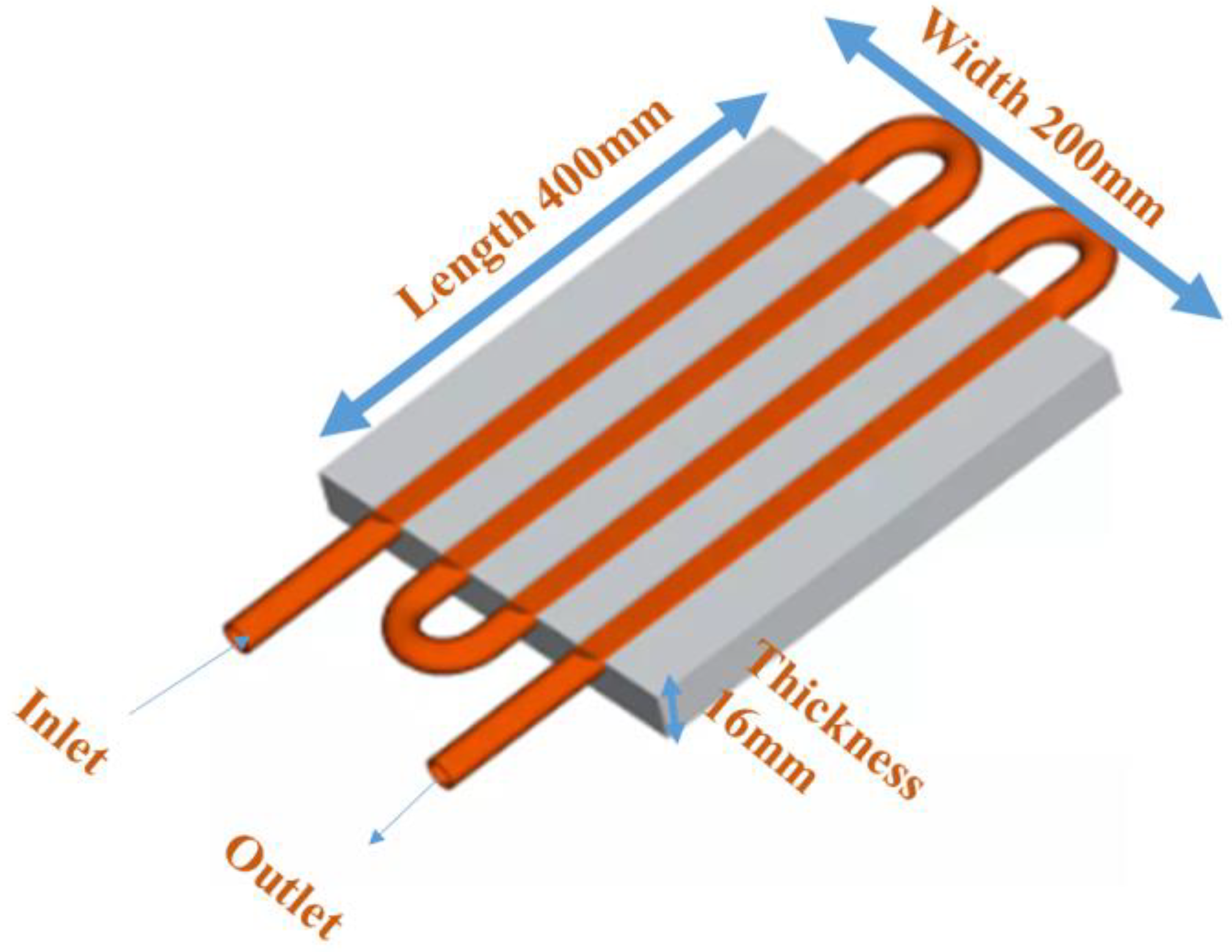
| Liquid cold plate size | 400 mm × 200 mm × 16 mm |
| Maximum Diameter of the outer channel (mm) | 9 mm |
| Channel pass | 4 |
| Working liquid | 45 |
| Channel | Cu |
| Working coolant temperature range (°C) | 5–20 |
| C-Rate [C] | Predicted Battery Temperature, [°C] @ Mineral Oil | Predicted Battery Temperature, [°C] @ Water/Glycol [50% + 50%] |
|---|---|---|
| 0.5 | 23.10 | 20.44 |
| 1 | 27.30 | 21.00 |
| 2 | 41.40 | 23.60 |
| 3 | 59.00 | 27.00 |
| 4 | 79.00 | 31.00 |
| 5 | 101.00 | 36.00 |
| C-Rate [C] | Predicted Battery Temperature, [°C] | Predicted Battery Temperature, [°C] @ 5% Variation in Charging Current + Heat Transfer Coefficient | Predicted Battery Temperature, [°C] @ 10% Variation in Charging Current + Heat Transfer Coefficient | |||||||
|---|---|---|---|---|---|---|---|---|---|---|
| Heat Transfer Coefficient [W·m−2·K−1] | No Variation | +5% Variation | −5% Variation | Relative Error @ +5% (%) | Relative Error @ −5% (%) | +10% Variation | −10% Variation | Relative Error @ +5% (%) | Relative Error @ −5% (%) | |
| 1 | 2647 | 21.00 | 21.10 | 21.00 | 0.47 | 0.00 | 21.20 | 20.90 | 0.95 | 0.47 |
| 2 | 3432 | 23.60 | 23.80 | 23.40 | 0.84 | 0.84 | 24.00 | 23.00 | 1.69 | 2.54 |
| 3 | 4321 | 27.00 | 27.50 | 26.50 | 1.85 | 1.85 | 28.00 | 26.00 | 3.70 | 3.70 |
| 4 | 5165 | 31.00 | 32.00 | 30.50 | 3.22 | 1.61 | 33.00 | 29.50 | 6.45 | 4.83 |
| 5 | 5976 | 36.00 | 37.00 | 35.00 | 2.77 | 2.78 | 39.00 | 34.00 | 8.33 | 5.55 |
Publisher’s Note: MDPI stays neutral with regard to jurisdictional claims in published maps and institutional affiliations. |
© 2022 by the authors. Licensee MDPI, Basel, Switzerland. This article is an open access article distributed under the terms and conditions of the Creative Commons Attribution (CC BY) license (https://creativecommons.org/licenses/by/4.0/).
Share and Cite
Shahjalal, M.; Shams, T.; Hossain, S.B.; Roy, P.K.; Jion, A.A.; Ahsan, M.; Chowdhury, J.I.; Ahmed, M.R.; Alam, S.B.; Haider, J. A Numerical Thermal Analysis of a Battery Pack in an Electric Motorbike Application. Designs 2022, 6, 60. https://doi.org/10.3390/designs6040060
Shahjalal M, Shams T, Hossain SB, Roy PK, Jion AA, Ahsan M, Chowdhury JI, Ahmed MR, Alam SB, Haider J. A Numerical Thermal Analysis of a Battery Pack in an Electric Motorbike Application. Designs. 2022; 6(4):60. https://doi.org/10.3390/designs6040060
Chicago/Turabian StyleShahjalal, Mohammad, Tamanna Shams, Sadat Bin Hossain, Probir Kumar Roy, Arafat Alam Jion, Mominul Ahsan, Jahedul Islam Chowdhury, Md Rishad Ahmed, Syed Bahauddin Alam, and Julfikar Haider. 2022. "A Numerical Thermal Analysis of a Battery Pack in an Electric Motorbike Application" Designs 6, no. 4: 60. https://doi.org/10.3390/designs6040060