
Event-Based PID Control of a Flexible Manufacturing Process
by
 , , , and
Octavian Duca
1,2,* ,
,
Eugenia Minca
1,3, 
Adrian Filipescu
1,4 ,
,
Daniela Cernega
4,
Razvan Solea
4 and
and
Claudiu Bidica
1 1
Doctoral School of Fundamental Sciences and Engineering, “Dunarea de Jos” University of Galati, 800008 Galati, Romania
2
Institute of Multidisciplinary Research for Science and Technology, “Valahia” University of Tâgoviste, 130024 Târgoviste, Romania
3
Department of Automation, Computer Science and Electrical Engineering, “Valahia” University of Tâgoviste, 130024 Târgoviste, Romania
4
Department of Automation and Electrical Engineering, “Dunarea de Jos” University of Galati, 800008 Galati, Romania
*
Author to whom correspondence should be addressed.
Inventions 2022, 7(4), 86; https://doi.org/10.3390/inventions7040086
Submission received: 26 August 2022
/
Revised: 19 September 2022
/
Accepted: 21 September 2022
/
Published: 26 September 2022
(This article belongs to the Special Issue Perspectives and Challenges in Doctoral Research—Selected Papers from the 10th Edition of the Scientific Conference of the Doctoral Schools of “Dunărea de Jos” University of Galati (SCDS-UDJG))
Abstract
:In most cases, the system control is made in a sampled manner, measuring the controlled value at a predefined frequency given by the sampling time. However, not all processes provide relevant information at regular intervals, especially in manufacturing. To reduce the costs and complexity of systems, event-based measuring is necessary. To control this kind of process, an event-based controller is needed. This poses some challenges, especially between the event-triggered measurement, as the process runs in an open loop. In the literature, most event-based controllers are based on the comparison of the error value with a predefined value and activate the controller if this value is crossed. However, in this type of controller, the measured value is measured at a predefine interval and is not suited for most event-based processes. In manufacturing systems, the most usual event-based process is represented by the conveyor transportation system. In this process, the product position is measured only in key locations on the conveyor. For the optimal operation of a flexible manufacturing system, the presence of a product in a key location at predetermined intervals is necessary. For this purpose, this article presents an event-based PID controller implemented on a conveyor transportation system.
1. Introduction
In a flexible manufacturing environment, most processes need precise control of the output value, especially the transport durations. These values cannot always be measured in a continuous manner, basing the control of the process on a discrete event measurement [1]. Especially in the transportation of the product in the flexible manufacturing system, the measurement of the product position is made based on binary sensors at a predefined location [2]. This determines the necessity for event-based control of the process. In most cases, this event-based control is made in a non-adaptive manner [3]. The control is usually made using a rule-based controller that sets a predefined control value based on an event [4]. In some cases, the controller needs a higher degree of adaptability to cope with variations in the system [5].
In most types of controls, the output value is measured at regular intervals, so the update of the control value is made in a time-triggered manned [6]. Even if studied extensively, the time-triggered control cannot cope with most of the event-based processes, especially because of the asynchronistic behavior of the system and, in some cases, the binary measurements [7]. To compensate for the asynchronistic behavior, some proposals were made in the literature but only for measurement losses, not being suited for an even-based control [8]. In the literature, event-based control, e.g., the arrival of a product to a certain location as an event trigger, has little coverage [6]. In most event-based control studies, the event-trigger is given by arriving at the error level of the output to a certain predefined value [9,10]. This type of even-based control is unsuitable for most event-based processes [11].
Based on event-triggered control, by combining it with impulsive control, further development of event-triggered impulsive control was proposed. In this type of control, the conditions and functions of the event-trigger are pre-set and some specific events determine impulsive instants [12,13,14].
This type of event-based control has as objective the reduction of control value updates and, as a result, the reduction of computational and power usage, especially in low-power devices [15]. However, to measure the error level, it is necessary to measure the output value at a certain predefine duration [16]. This can be done using an intelligent sensor or allocating controller computational power. This is not suitable for most event-based processes, as the output value cannot be measured at regular intervals.
The differences between the time-triggered mechanism and the event-triggered mechanism, based on the occurrence of a preset event, stirred up research, especially in the state estimation of a system [17,18,19]. In estimating the state and controlling the system, fuzzy or neural network control is implemented [20,21,22].
In the manufacturing process, the product position is known only at key locations, usually measured using binary presence sensors. Using this type of sensor, an error-based event-triggering or time-triggering controller cannot be implemented [23]. The inability to implement most types of controllers is due to the measurement of the continuous process in a discreet manner [24]. The number of discreet values measured would be defined by the key locations on the system and would determine the continuous running of most control algorithms [25]. This continuous running would be determined by the error values, but as the measurement is done in a few key points, the controller would run based on the old value [26]. This can determine unintended results due to the small number of input values.
In the literature for event-trigger control, multiple solutions are proposed, such as the event-trigger sliding mode control in [27] or the use of a Markov model in [28]. However, in terms of some advantages, a PID control can be implemented, similar to [29] or [16]. In most cases, the PID controller is adopted for simple structure and adaptability in most control cases. In this article, a control algorithm similar to the error event-based algorithm in [9,16] is proposed, as the computation of the controller will start only at the moment a certain event is happening. As the error level trigger case cannot be implemented in the case of a conveyor, a modification of the event trigger is implemented. An activation of the control algorithm is proposed based on the arrival of the product at a certain point on the conveyor and a sensor is activated. From the perspective of the number of activations, the necessary event-based controller would have fewer activations than the proposed literature controllers. The number of activations is given by the key locations where the position of the product is measured.
This paper is organized as follows: Section 2 presents the time-triggered PID control as a reference base in the event-base controller and details the error variation event-trigger controller. Section 3 presents the flexible manufacturing process in which an event-based controller is necessary. Section 4 presents the proposed event-based algorithm and the expected results of the controller in a transportation system. Section 5 presents the implementation of the controller in a flexible manufacturing system and the results obtained.
2. PID Control
As PID control is one of the most studied types of control, in controlling the event-trigger transportation system, PID event-based control was considered. For better comprehension of the proposed event-based algorithm in this chapter, the time-based PID control and the error trigger event-based PID control found in the literature will be reviewed.
2.1. Time-Based PID Control
For the PID control, the S-domain equation that represents the base for the controller is given by:
defining the command value in the S-domain, based on the error between the reference and actual value of the output, [9].
The control equation is composed of three parts: proportional, integral and derivative, represented by , defined by the integral gain , the integral time , and derivative time . The parameters of these three parts are modified regarding the controller specifications to obtain the desired performance. In some cases, the weighting of the setpoint can be applied for a more flexible structure. The structure of the three components of the PID controller can be represented as follows:
with defining the integral component gain, and the derivative component gain [15].
To compensate for the possibility of high-frequency noise from the measurements to the derivative part, a low-pass filter can be added, resulting in:
with as the filter gain [15].
In the case of a real process, the value of the command can increase or decrease until a certain point, as more controlled elements have minimal and maximal values. To corelate the controller with the physical capabilities of the system, a set of command saturation rules needs to be implemented, resulting in the following:
with representing the command value sent to the executing element, is defined by a minimal value, , and a maximal value, .
If the command value falls outside the desired interval, in addition to the saturation rules, an anti-windup method must be implemented. This eliminated the delays introduced by the integrator factor. The most commonly used method is the clamping method. This method disengages the integrator factor for the duration in which the command falls outside the desired limits.
Considering the mapping of the PID controller from the S-domain to the discrete-time domain, the following is obtained:
with the control value in the time domain , and it’s components for the proportional, integral and derivative parts, where represents the instant moment of the sampling, having the constant sampling period [15]. Similar to the continuous time controller relation to the S-domain, the relation is similar in the Z-domain with discrete time. The proportional part results in:
with the discrete time form as [15]:
In the case of the integrator and derivative parts of the PID controller, several solutions can be applied. One of the solutions, backward difference approximation, is a method based on first-order Taylor series expansion. In this expansion resulting in
relating to the time domain as [15]:
The approximations in the case of the discrete-time controller are more accurate as the sampling duration, , is smaller.
2.2. Error Trigger Event-Based PID Controll
The first proposed event-based PID controller consisted of two main parts: an event detector and an PID controller activated based on the detected event. The event detector, with time-based sampling, ensures that the error value is maintained in a certain range and that the duration since the last controller activation is not over a certain limit. Similar to the time-sampling PID, the event detector samples the controlled value at an sampling period. Based on the setpoint and the measured value, the event detector sends a signal to the PID part of the controller when the error level falls outside a certain predefined limit, considered an event. As presented in the literature cases, the event-trigger is considered to be the absolute error value, , crossing a predefined level. As a result, the event condition is [9,15]:
with , with a variable activation period determined in the moment a new event is taking place.
After an event is detected, the PID event-based controller updates the control signal based on the measurements received from the event detector and the previous controller values. In between the event-triggers, the control signal is constant for the duration. Applying the backward difference method approximation in the case of the integrative and derivative parts results in [16]:
having replacing the constant period in Equation (9).
Considering the event-triggering condition from (10), as an event is recorded only when the error value is larger than a certain level, the activation interval can become very long, as the variation of the output can be very small. Some compensations are applied predominantly to the integrator and derivative parts. A diminishing factor for the activation interval is introduced, resulting in the reduction of after a long duration of steady output, reducing its effects on the control values. This approach is very similar to the anti-windup method, compensating for errors in the case of saturation of the control value.
For the integral term, an exponential function determines the decrease in the impact of the activation interval as the steady-state duration increases [15,16]:
with used to directly influence the importance of the activation interval. This determines the value to get closer to when the activation duration is small and to get very small when the activation duration gets longer.
In the case of the derivate part, similarly, results in:
with used to increase or decrease the influence of the exponential factor. The results show that the value will be closer to when the activation value is small and closer to the last activation period when the activation duration gets bigger.
3. Flexible Manufacturing System
Considering the literature in the event-based control area, the research is centered on the reduction of computation power through the reduction of controller activation and control values. This control is based on the sampled measurement of the output value. This is not always possible in a manufacturing system, for example, as the position of a product is measured only in key positions. In this chapter, the hardware and process structure of the flexible manufacturing system considered in the application of event-based control will be presented.
3.1. Flexible Manufacturing System Hardware
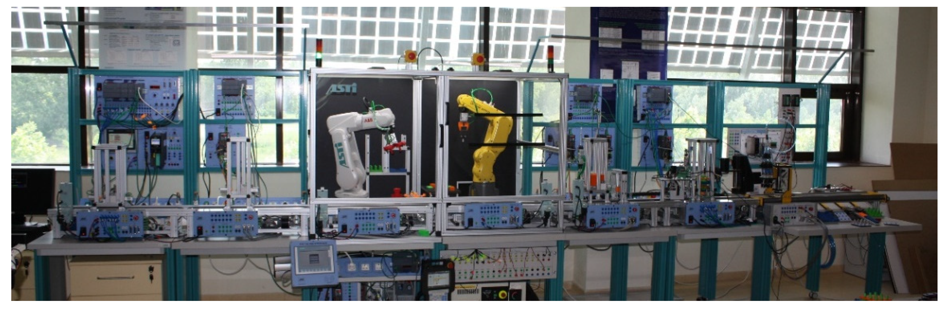
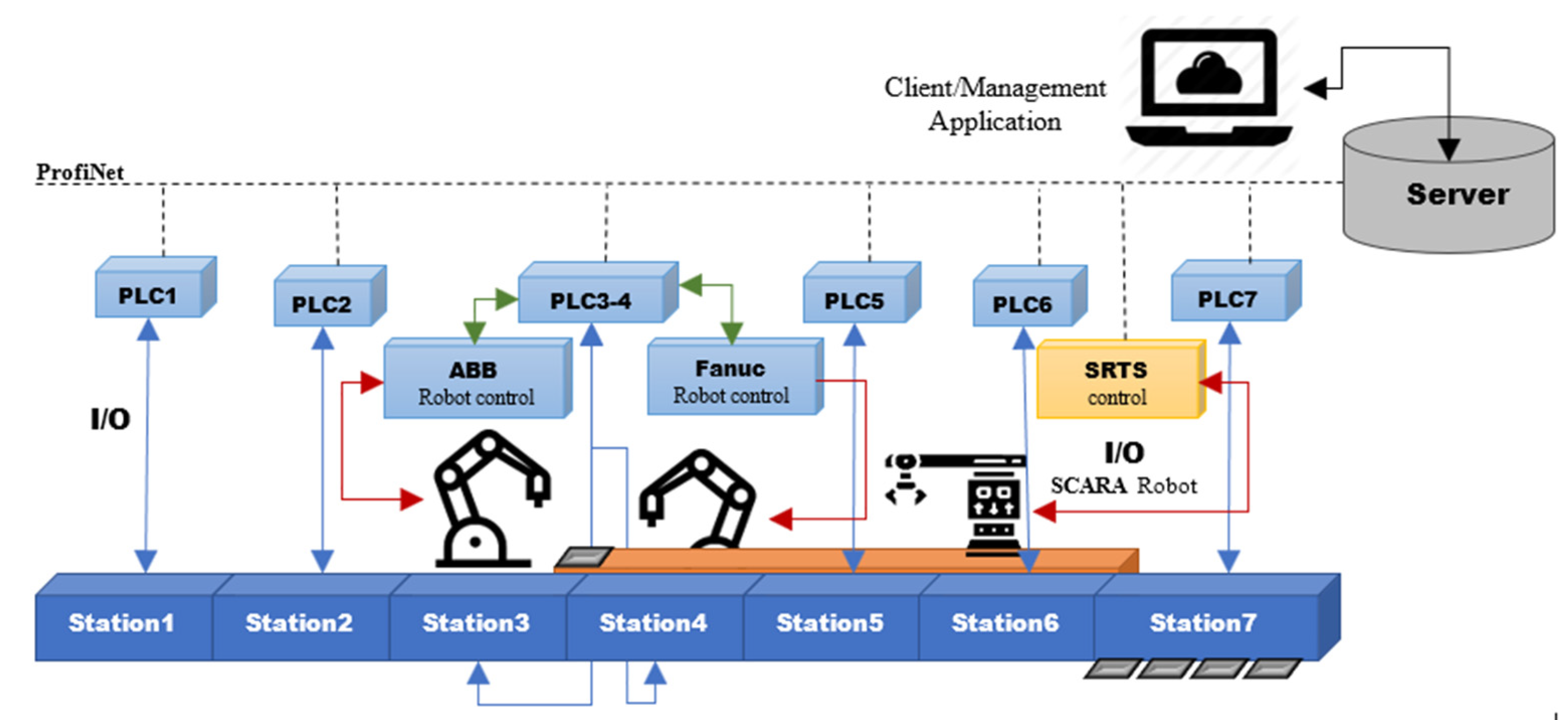
The flexible manufacturing system (FMS) is composed of 7 interlocked workstations arranged in a linear manner (Figure 1). The FMS is equipped with three robotic systems, two robotic arms, placed in two of the workstations and a SCARA robotic transportation system (SRTS) placed parallel to the workstations. Each workstation is equipped with a PLC used in the individual control of the station (Figure 2). This also ensures the flexible integration of equipment into the manufacturing system. All PLCs are interconnected on a ProfiNet network, ensuring fast information transmission between PLCs. Having the possibility of PLC interoperability, decision making is made in two stages. This is composed of centralized decision making, centered on the optimization of production, and local decision making, which ensures the achievement of the proposed production durations.
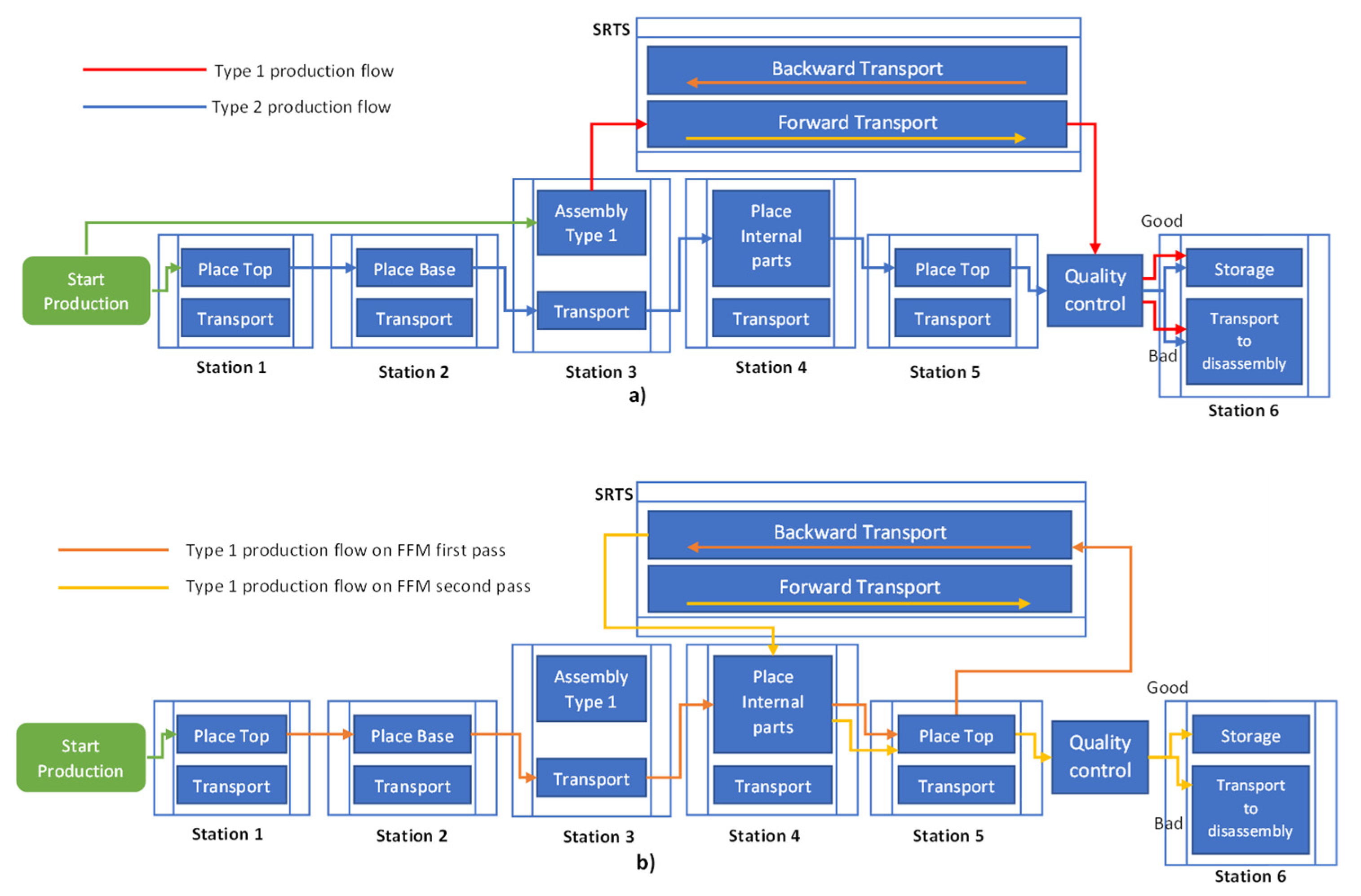
Besides the flexibility given by the possibility of integrating new equipment with ease, the FMS presents flexibility in the production process, being able to produce a multitude of products with a minimum of equipment. This is ensured through two production concepts: flexible flow manufacturing (FFM) and flexible manufacturing in cells (FMC). On the FFM, the product travels in a linear manner through 5 workstations of the FMS, schematically represented in Figure 3, each station performing an assembly operation. In FFM production, one of the robotic arms will perform an assembly operation, placing a series of internal parts in a personalized manner, based on the client’s request.
In the FMS, two principal types of products are considered for production: a single internal layer product and a multiple internal layer product. For the multi-layered product, a series of assembly operations are repeated. Both products can be assembled in the FFM process using SRTS. For the multi-layer product, the SRTS transports the product back to one of the previous stations from where a new set of assembly operations are performed. This ensures that the assembly uses a minimal amount of equipment.
For the FMC process, the second robotic arm is used. At workstation 3, the robotic arm can perform some assembly operations on the FFM or perform a competing assembly of a product in a dedicated area. Workstation 3 is equipped with warehouses for each component, allowing for the assembly of any type of product. From the FMC assembly area, the SRTS transports the product on the FFM to the quality control (QC) area at the entry of workstation 6. The FMC is considered only the production of multi-layer products, as robotic arm flexibility gives the possibility of manufacturing more complex products in a much shorter time.
The intersection of the FFM and FMC processes in the QC area and the usage of the SRTS in both processes create some challenges in the optimization of the entire manufacturing system. To ensure the optimal transportation of products on the FMS, the SRTS is placed parallel to the FFM transportation conveyor. This ensures the usage of minimal workstations but also the minimization of some transportation durations.
The placement of the robotic arms is made considering the possibility of increasing the personalization of each product. To compensate for the increased complexity of the assembly process, a robotic arm was introduced in the specific personalization workstation, permitting the manufacturing of a multitude of products based on client requests. The client request is received directly by the FMS, the manufacturing system being connected to a local server. The server receives the client request and processes the information through an optimization algorithm. The output of the algorithm is represented by a production schedule based on assembly and transportation duration. To ensure these durations, a control algorithm is necessary in each station, especially on the transportation side, that can compensate for some of the assembly delays.
3.2. Flexible Manufacturing System Production Process and Control Necessities
Given the production flows of the two considered types of products (Figure 4), in some situations, we have intersecting paths for some products. To ensure optimal manufacturing, the products must arrive at designated locations at a certain time in the process. In the case of the SRTS transport of products, the transport duration is known to be ensured by the robot control system.
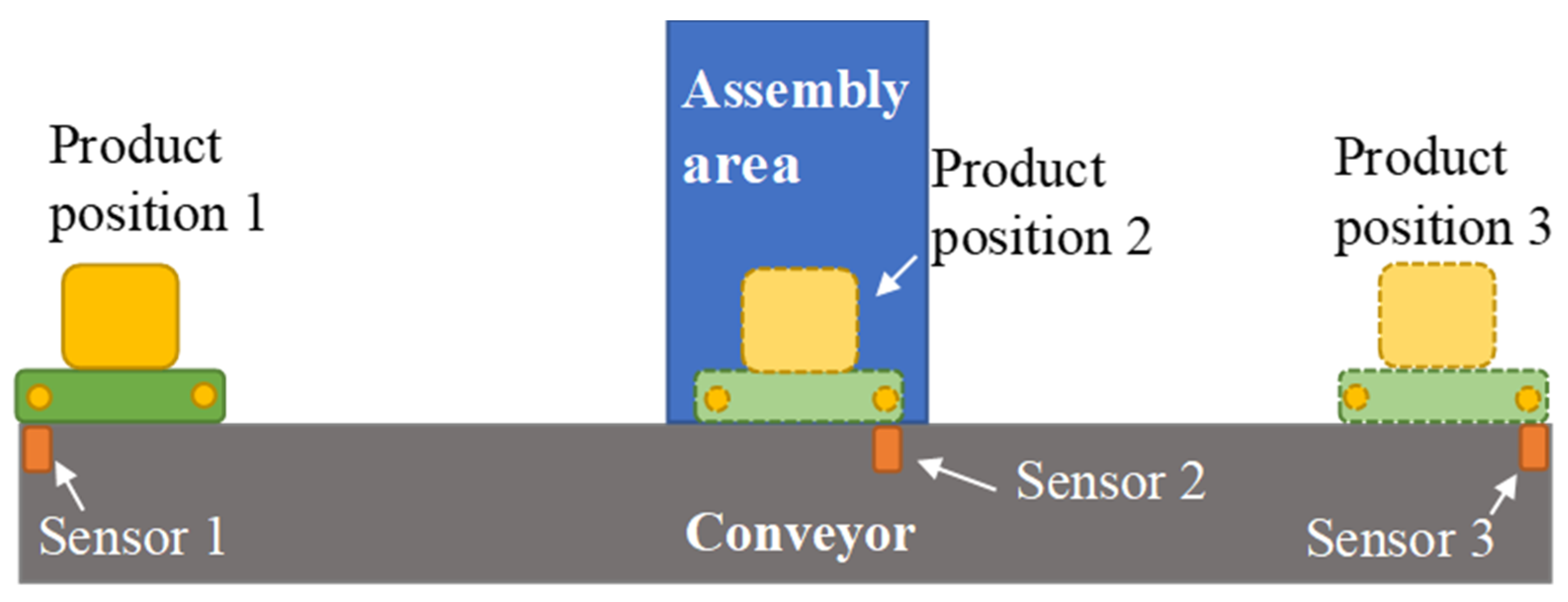
In the case of workstation transportation using conveyors, this duration cannot always be guaranteed with sequential control. On a workstation, the position of a product is measured in three key locations using binary location sensors (Figure 3). On a basic conveyor, the position of a product is measured at the entry of the station, the exit and the working area. At a certain moment on the conveyor, only one product is present. In the classic programming of the station PLC, a series of events starts when a certain sensor is activated and continues in a sequential manner until the next sensor is activated. This method of control cannot ensure the transportation of a certain product between two points in a predefined amount of time. To ensure that a product arrives at a certain point at a certain time, an adaptable control algorithm must be implemented.
In the case of a workstation, perturbations on the arrival of a product to a certain location can be introduced mainly by the assembly process. If the process has a longer duration, then the transportation system can compensate for the delay by varying the speed. The control algorithm must also consider some limitations. As a transportation system in a manufacturing process, the direction of transportation should be predefined, meaning that the product cannot travel backwards to a certain location. This can introduce some errors, as the product cannot be positioned at a precise point at the sensor location but position around it. In this case, the error is expected to be lower than the sequential control.
The second factor considered in the control algorithm is the minimal and maximal command values. To ensure that the command value is kept in the desired range, a saturation method is applied. This ensures that the system runs within the desired parameters.
4. Event-Based PID Conveyor Control
As the event-based error triggering method presented in the literature cannot be applied, some modifications were made to this type of control. Considering the number and type of sensors, one of the modifications to the control algorithm needs to be activated if the product is present at one of the sensors. This ensures that the position of the products is known with precision. This leads to a new control algorithm, which is presented in the next pages.
4.1. Event-Based PID Algorithm Structure
Based on the literature on event-based PID with the error level as a trigger event, a new algorithm, Algorithm 1, was designed to replace the error level trigger with a product position trigger. This is accomplished by sending an activation signal to the control part of the algorithm. Based on the product position on the conveyor and the reference set by the production stage, the algorithm calculates the speed of the conveyor and sends it to the conveyor motor. Based on the sensors’ positions, in key locations, after the first algorithm activation and arriving of the product to the second sensor, the system will wait for the completion of the production processes and then set the next position reference that starts the transportation. Additionally, between the sensors, the algorithm retains the last known position of the product. In the case of the workstation presented in Figure 3, the activation of the control algorithm is determined by the activation of the sensors present at the entry, assembly area and exit of the workstation. This results in the event-based control algorithm presented below, which calculates the control signal for the transportation of a product between two locations.
| Algorithm 1: Algorithm for Event-Based PID Control. | ||||||
| Input: | y_ref //position reference given by production stage | |||||
| y //product location given by sensor activation | ||||||
| // actv event triggered by sensors | ||||||
| actv= | 1, if one of the sensors is active | |||||
| 0, otherwise | ||||||
| Output: u_com //conveyor speed | ||||||
| 1 | //Calculate time between updates: t_pres = t_pres + t_nom | |||||
| 2 | if (actv = 1) | |||||
| 3 | er = y_ref − y | |||||
| 4 | up = K * (beta * y_ref − y) | |||||
| 5 | ud = Td/(N * t_pres + Td) * ud_old − K * Td * N/(N * t_pres + Td) * (y − y_old) | |||||
| 6 | ui = ui_old + K/Ti − t_pres * e | |||||
| 7 | u = up + ui + ud | |||||
| 8 | //saturation and anti-windup | |||||
| 9 | if (u < u_inferior) then //command under a limit | |||||
| 10 | u_com = u_inferior | |||||
| 11 | ui = ui_old | |||||
| 12 | else if (u > u_superior) then//command over a limit | |||||
| 13 | u_com = u_superior | |||||
| 14 | ui = ui_old | |||||
| 15 | else | |||||
| 16 | u_com = u | |||||
| 17 | ui = ui_old + K/Ti − t_pres * e | |||||
| 18 | end | |||||
| 19 | end | |||||
| 20 | //update values | |||||
| 21 | ui_old =ui | |||||
| 22 | ud_old =ud | |||||
| 23 | y_old = y | |||||
| 24 | t_pres = 0 //reset of working time | |||||
| 25 | End | |||||
4.2. Product Conveyor Transportation Simulation Study
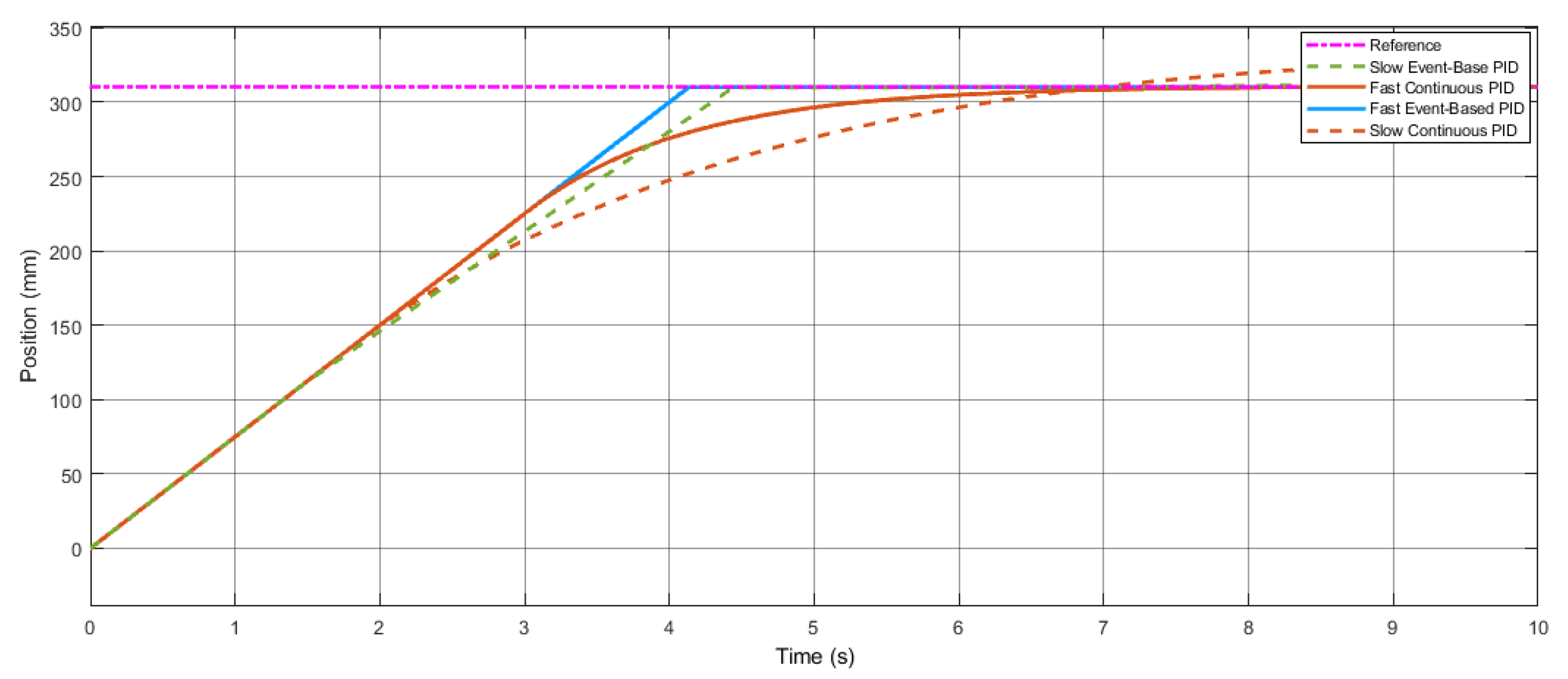
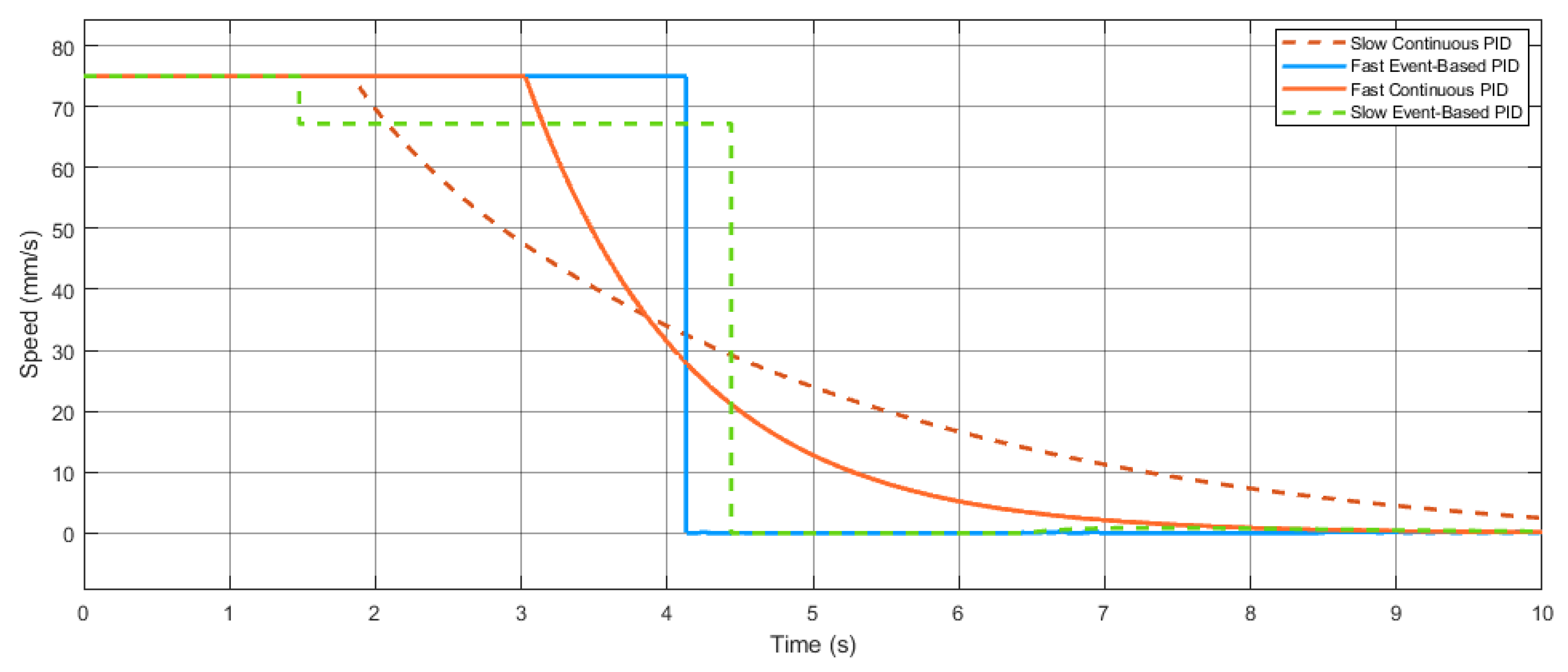
Considering conveyor transportation, the process has as output the product position and as an input the speed of the conveyor. In the S-domain, this translates into a simple transfer function . Based on the transfer function, a series of simulations were made to observe the behavior of the system with event-based and continuous PID control. Two situations were considered, one in which the continuous PID controller output is saturated most of the time (Figure 5), resulting in a continuous speed output of the event-based PID (Figure 6). The other situation is considered so that the event-based PID controller changes the output value as the controller is activated the second time the product activates the same sensor.
The first activation of the event-based PID is determined by the product arriving in the sensor area, determining its activation. The second activation is determined by arriving at the end of the product in the activation area of the sensor. This allowed us to determine the position of the product given by the length of the product. Based on the second activation, a recalculation of the control output is made and an update is made.
It can be observed that the error between the proposed event-based PID and the continuous PID results bets larger with an increase in the transition time. This is determined by the greater speed at the start of the continuous PID, which is similar to the one in the event-based PID. However, in an event-based PID, the speed is calculated only when a sensor is activated; the speed will be kept constant until a new sensor activation occurs.
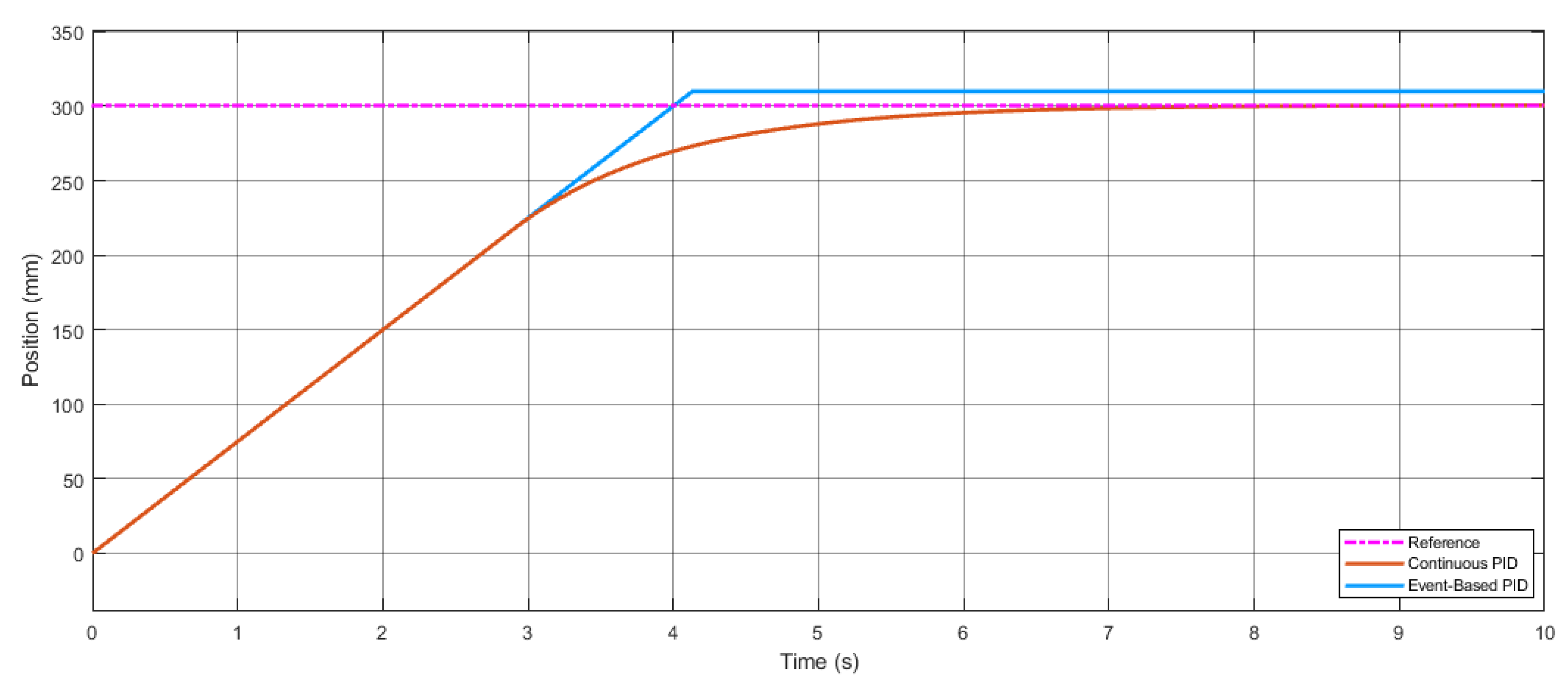
As the location of the product is usually measured by binary sensors on key locations on the conveyor, in the case of event-based control, the setpoint needs to take values from a discrete interval, given by the number of sensors. This represents the main case of even-based control, as if the setpoint is outside the discrete interval considered, then the product will stop at the next sensor after the setpoint. This is determined by the inability to measure the position of the product between sensors. This could be compensated for by the introduction of digital twins, but this represents future research on this subject. In Figure 7, the error between the setpoint and the event-base PID result can be observed if the setpoint takes a value outside the predefined discrete range. The stabilization of the event-based PID above the setpoint is also given by the introduction of saturation on the command value, assuming that the conveyor can only travel in one direction.
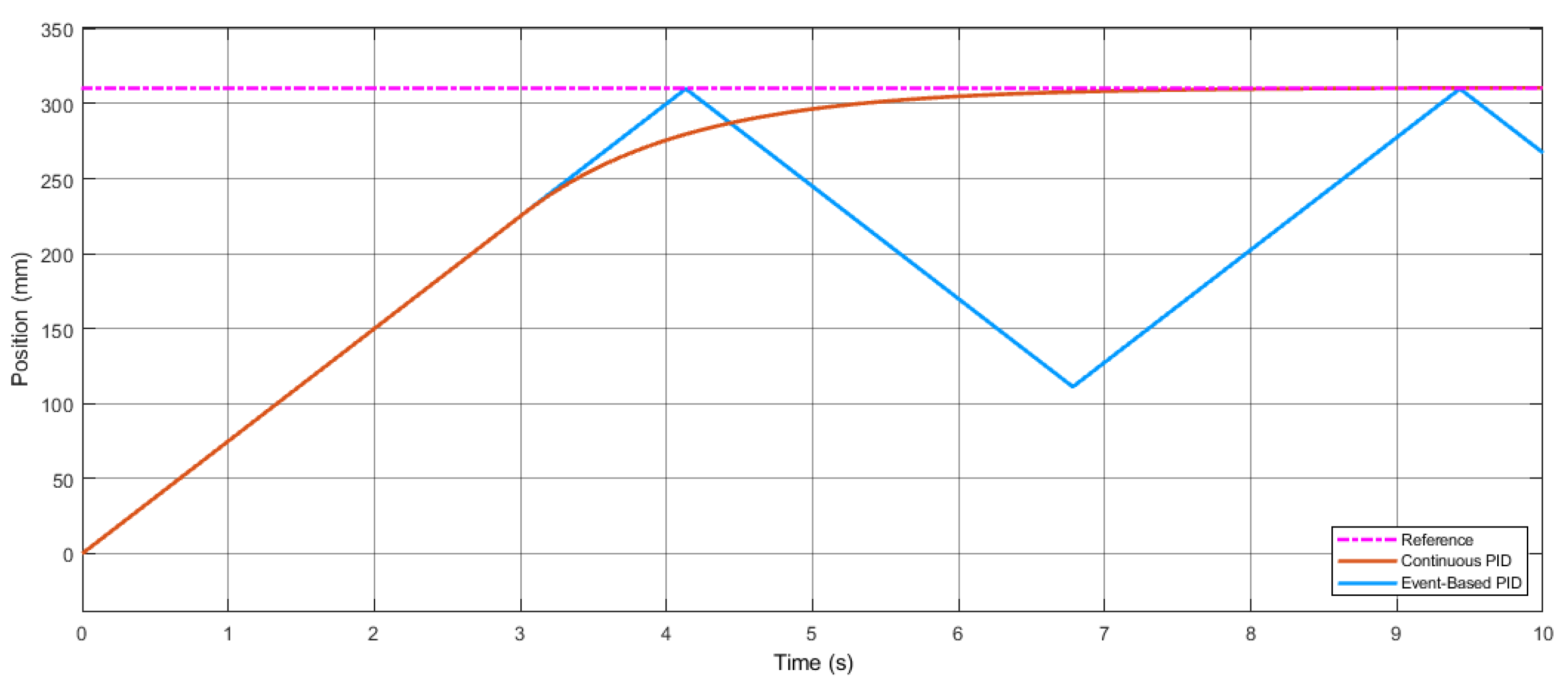
If saturation over the control value would not be implemented or the limitation would determine a bidirectional travel of the product, the system would become unstable. In the case of setting a setpoint outside the defined interval, the product would start to travel backward from the sensor after the setpoint to the wone before it. As the product could not settle on the desired setpoint, an infinite oscillation between the two sensors would start. This would also be possible in normal operation, as the setpoint takes values in the desired interval. As the product arrives at a certain sensor, the inertial forces and conveyor error determine the product to overshoot the sensor, triggering an oscillation between sensors (Figure 8). This problem is eliminated by limiting the control value so that the conveyor travels only in one direction, as bidirectional travel is not needed.
5. Flexible Manufacturing System Conveyor Control
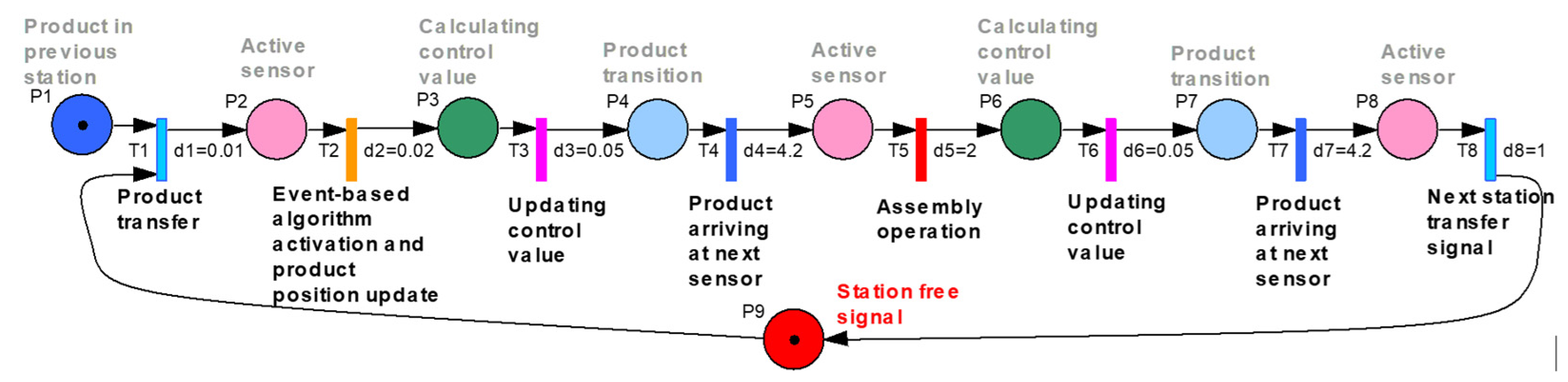
Based on the simulation results, an event-based algorithm was implemented, and a series of measurements were made on one of the FMS workstation conveyors. In addition to the calculations of the control value, a series of information transmission durations introduce some delays in system operations. These can be observed in the differences between the algorithm computation durations and the measurements but also by model, using a Petri net (Figure 9). For the simplification of the model, only the first activation of the control algorithm and the corresponding durations for the computation and transport until arriving at the second sensor were considered. This permits more uniform modeling for all situations. The first operation in the conveyor process starts with the previous conveyor, with the transfer of the product and the activation of the first sensor. This is followed by the activation of the control algorithm and the calculation of the control value. This value is sent to the system, and product transportation starts. After the product arrives at the second sensor, assembly operation is started. After the assembly operation is finished, the control value calculation begins. With the control value updated, new transportation of the product is started. As the product arrives at the third sensor, the product is transferred to the next station.
Figure 10 shows the duration of each step of the conveyor process, from the algorithm activation to the product leaving the workstation. From the control update duration, the time taken by the control value calculation and sending the obtained information to the conveyor can be observed. The value of this duration, even small, can influence the entire production system, especially the production optimization algorithms. This computation and information transmission duration also explain some of the differences between the control algorithm and the measurement duration.
As at a certain moment on the conveyor is present a single product, represented by the station-free signal in the Petri net, a non-Zeno behavior can be ensured. Zeno behavior is defined by the probability of the execution of an infinite number of events in a finite duration. This is represented in most cases as requiring the execution of two or more events at the same moment in time, as presented in [30,31]. As only one product is presented on the conveyor, the activation of the control algorithm is ensured in a sequential manner, as the product arrives at one of the three positions. As one of the sensors is activated, the controller start is triggered. As none of the events that are executed are considered instantaneous and the events are proposed in a sequential manner, the system has a non-Zeno behavior, as illustrated in [30]. Some Zeno behavior can be introduced by faults in the hardware of the system. As certain defects on the sensor side can determine the false activation of certain sensors, the system can interpret the fault as the product being at two positions at the same time, introducing Zeno behavior in the controller. This behavior can be used as a fault detector or eliminated by introducing certain precautions in the system software.
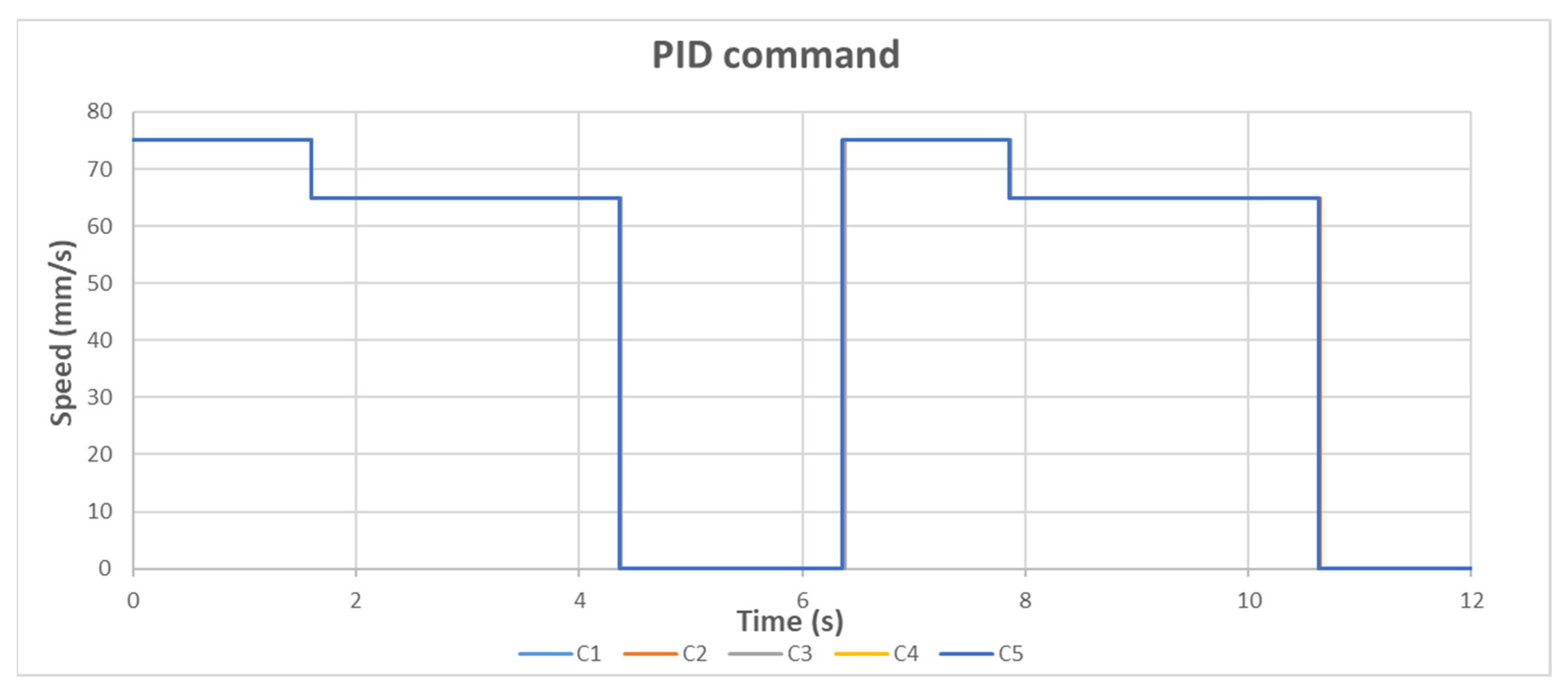
In Figure 11, Figure 12 and Figure 13, the control algorithm and model implementation measurements can be observed. Figure 10 represents the control value sent to the conveyor based on the event-based control algorithm. In the graphic, the second update of the control value can be observed as the back of the product crosses the sensor, reducing the conveyor speed. This follows the pattern present in the control algorithm simulation, with minor modifications introduced by data transmission delays and calculation approximations. As the same algorithm is used on the first and second parts of the conveyor and the distances are similar, the results are identical, with minor differences.
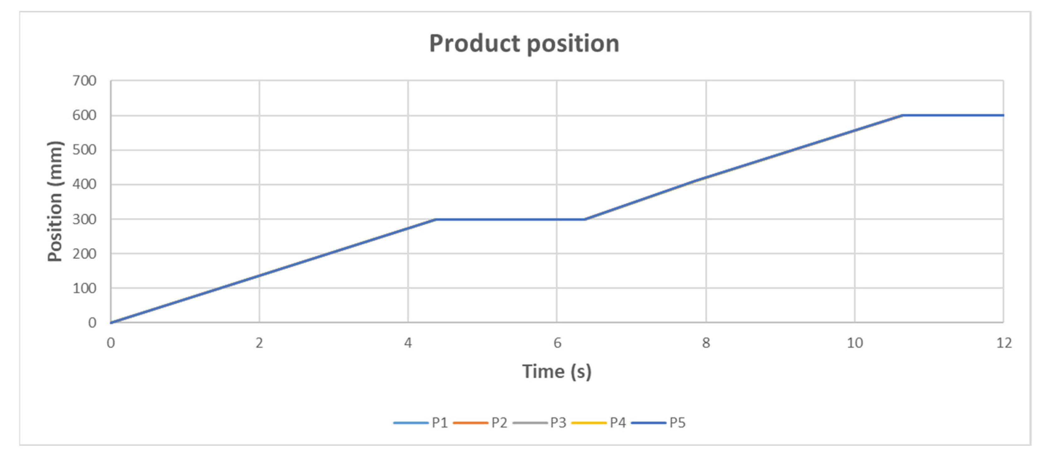
Based on the control value transmitted to the conveyor, Figure 12 shows the position of the product on the duration between entering the workstation and waiting to leave it. Considering the small variation in speed between the product entering and leaving the sensor area, a notable modification in the product transition rate is not visually observable.
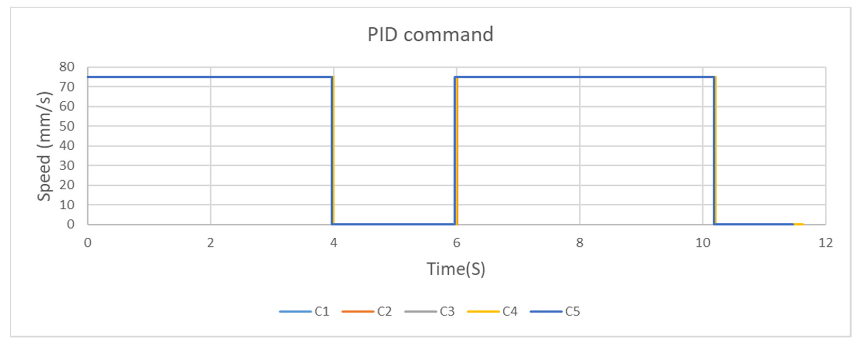
In cases in which some durations need to be compensated for based on assembly delays, the controller can set the control value for the conveyor at the maximal value for the entire transport duration between the two locations. These results can be observed in Figure 13, where, for the entire duration of transport, the conveyor speed is kept at the maximum value. This ensures compensation for possible delays.
The proposed algorithm presents control possibilities for a limited number of transportation cases. These cases cannot be controlled in the usual manner, as the measurement of the controlled value is made in a discrete manner. These discrete measurements, done mostly by binary sensors, cannot ensure an optimal number of measurements for a standard PID control. In most cases, and especially in industry, this type of system is controlled using a sequential algorithm. In these usual algorithms, a predefined value is set to the control value, depending on the algorithm step the system is at the given moment. This can be detrimental in some cases if a variable control value is needed.
One type of sequential control algorithm can be based on a Petri net model of the manufacturing system; this determines what actions need to take place at a certain sensor activation. As the resulting actions are predefined, the command values are mostly set at an optimal working speed. This determines a behavior similar to the system, as in the event-based maximal speed case in Figure 13, where the control output is kept at a certain level as the product is transported between the desired positions. This type of control cannot adapt easily to certain disturbances compared to other types of control.
In the case of the proposed event-based algorithm, the best results are obtained if the system is run as a faster process, as the saturation of the control value influences the output of the controller. This brings the event-based controller output closer to the continuous controller.
Another important aspect of the proposed event-based controller is the rapid increase or decrease in the control value. This can further limit the applicability of the controller. In the case of transporting products with a high inertial mass, this type of control can determine big positioning errors and hardware problems. However, in low mas product transportation, this type of problem should not have a definitive impact, permitting the implementation of such a controller.
6. Conclusions
In today’s manufacturing environment, most product position measurements are made in an event-triggering manner. As the product arrives in a key position, its location is updated. In most cases, the control of transporting a product between two key locations is carried out by a sequential control algorithm. In this type of control, one sequence of events is activated as the previous sections finish, and some sensors have achieved predefined values. However, using a predefined sequence and value in controlling product transportation limits the possibility of duration compensation in case of product delays. As in flexible manufacturing systems, products need to be at key locations at predefined intervals, so a rigid control algorithm cannot cope with the necessary control requirements.
In this situation, an event-based PID controller is presented for the presented fabrication system. Most of the event-based PID controllers presented in the literature have an event trigger set based on the error value. This means that the output of the system needs to be measured in a sampled manner at regular intervals. This is not possible in most manufacturing systems because the sensors are placed only in key positions.
Starting from the literature algorithms, the main improvement proposed in this article is represented by the modification of the event-trigger from an error level to a position activation event. This is representative of systems where the output of the system, in this case the product position, cannot be measured in a sampled manner. In this case, the error level of the output cannot be determined because the product position is determined only in key positions. This determines the necessity of introducing a new type of event-triggered, as proposed in this paper.
Based on the obtained results, the event-based controller can achieve similar results with the continuous PID in cases in which the control value is limited in a predefined range. In addition, this saturation of the control value results in the stabilization of the event-based controller, as without limitation, the controller would be unstable.
This type of event-based control could be improved by introducing a digital twin in the calculation of the control value and compensating for the error between the digital twin and the real system based on event-triggered measurements. This represents further research on event-based control, with this research being a reference base. Based on the obtained results, further comparisons can be made in developing a digital twin of the system and integrating it into the control loop.
Author Contributions
Conceptualization, O.D., E.M., A.F., R.S., D.C. and C.B.; methodology O.D., E.M., A.F., R.S., D.C. and C.B.; software, O.D.; validation E.M., A.F., R.S. and D.C.; formal analysis E.M., A.F., R.S., D.C. and C.B.; writing—original draft preparation O.D. and E.M.; writing—review and editing E.M., A.F.; supervision E.M., A.F.; project administration E.M.; funding acquisition E.M., A.F. and O.D. All authors have read and agreed to the published version of the manuscript.
Funding
This article (APC) was supported by the Doctoral School of Fundamental Sciences and Engineering, “Dunarea de Jos” University of Galati.
Institutional Review Board Statement
Not applicable.
Informed Consent Statement
Not applicable.
Data Availability Statement
Data availability is not applicable to this article as the study did not report any data.
Acknowledgments
The results of this work were presented to the 10th edition of the Scientific Conference organized by the Doctoral Schools of “Dunarea de Jos” University of Galati (SCDS-UDJG) http://www.cssd-udjg.ugal.ro/ (accessed on 10 May 2022), held on 9th and 10th of June 2022, in Galati, Romania.
Conflicts of Interest
The authors declare no conflict of interest.
References
- Kamble, S.S.; Gunasekaran, A.; Ghadge, A.; Raut, R. A Performance Measurement System for Industry 4.0 Enabled Smart Manufacturing System in SMMEs—A Review and Empirical Investigation. Int. J. Prod. Econ. 2020, 229, 107853. [Google Scholar] [CrossRef]
- Huang, D.; Lv, J. Run-to-Run Control of Batch Production Process in Manufacturing Systems Based on Online Measurement. Comput. Ind. Eng. 2020, 141, 106298. [Google Scholar] [CrossRef]
- Zhang, D.; Zhang, L.; Yu, Z.; Li, H.; Shu, L. Dynamic Output Feedback Control for Networked Control Systems: A Sum-Based Discrete Event-Triggered Approach. IFAC-PapersOnLine 2022, 55, 61–66. [Google Scholar] [CrossRef]
- Liu, L.; Li, X.; Liu, Y.-J.; Tong, S. Neural Network Based Adaptive Event Trigger Control for a Class of Electromagnetic Suspension Systems. Control. Eng. Pract. 2021, 106, 104675. [Google Scholar] [CrossRef]
- Borase, R.P.; Maghade, D.K.; Sondkar, S.Y.; Pawar, S.N. A Review of PID Control, Tuning Methods and Applications. Int. J. Dyn. Control. 2021, 9, 818–827. [Google Scholar] [CrossRef]
- Visioli, A. Research Trends for PID Controllers. Acta Polytech. 2012, 52, 144–150. [Google Scholar] [CrossRef]
- Durand, S.; Marchand, N.; Guerrero-Castellanos, J.F. Event-Based Stabilization of Nonlinear Time-Delay Systems. IFAC Proc. Vol. 2014, 47, 6953–6958. [Google Scholar] [CrossRef]
- Prabhat Dev, M.; Jain, S.; Kumar, H.; Tripathi, B.N.; Khan, S.A. Various Tuning and Optimization Techniques Employed in PID Controller: A Review. In Proceedings of International Conference in Mechanical and Energy Technology: ICMET 2019, India; Yadav, S., Singh, D.B., Arora, P.K., Kumar, H., Eds.; Springer: Singapore, 2020; pp. 797–805. ISBN 978-981-15-2647-3. [Google Scholar]
- Åarzén, K.-E. A Simple Event-Based PID Controller. IFAC Proc. Vol. 1999, 32, 8687–8692. [Google Scholar] [CrossRef]
- Durand, S. Event-Based Stabilization of Linear System with Communication Delays in the Measurements. In Proceedings of the 2013 American Control Conference, Washington, DC, USA, 17–19 June 2013; pp. 152–157. [Google Scholar]
- Ma, B.; Wang, Y.; Chen, G. Event-Triggered Type-2 Fuzzy-Based Sliding Mode Control for Steer-by-Wire Systems. Mechatronics 2022, 82, 102704. [Google Scholar] [CrossRef]
- Han, X.; Zhao, X.; Sun, T.; Wu, Y.; Xu, N.; Zong, G. Event-Triggered Optimal Control for Discrete-Time Switched Nonlinear Systems With Constrained Control Input. IEEE Trans. Syst. Man Cybern. Syst. 2021, 51, 7850–7859. [Google Scholar] [CrossRef]
- Zhu, W.; Wang, D. Leader-Following Consensus of Multi-Agent Systems via Event-Based Impulsive Control. Meas. Control. 2019, 52, 91–99. [Google Scholar] [CrossRef]
- Bai, Q.-Z. WeiTI-Event-Triggered Impulsive Optimal Control for Continuous-Time Dynamic Systems with Input Time-Delay. Mathematics 2022, 10, 279. [Google Scholar] [CrossRef]
- Durand, S.; Guerrero-Castellanos, J.F. Event-Based Digital PID Control. In Proceedings of the 2015 International Conference on Event-based Control, Communication, and Signal Processing (EBCCSP), Krakow, Poland, 17–19 June 2015; pp. 1–7. [Google Scholar]
- Durand, S.; Boisseau, B.; Marchand, N.; Guerrero-Castellanos, J. Event-Based PID Control: Application to a Mini Quadrotor Helicopter. Control. Eng. Appl. Inform. 2018, 20, 36–47. [Google Scholar]
- Heemels, W.P.M.H.; Johansson, K.H.; Tabuada, P. An Introduction to Event-Triggered and Self-Triggered Control. In Proceedings of the 2012 IEEE 51st IEEE Conference on Decision and Control (CDC), Maui, HI, USA, 10 December 2012; pp. 3270–3285. [Google Scholar]
- Ge, X.; Han, Q.-L.; Zhang, X.-M.; Ding, L.; Yang, F. Distributed Event-Triggered Estimation Over Sensor Networks: A Survey. IEEE Trans. Cybern. 2020, 50, 1306–1320. [Google Scholar] [CrossRef]
- Qin, J.; Ma, Q.; Shi, Y.; Wang, L. Recent Advances in Consensus of Multi-Agent Systems: A Brief Survey. IEEE Trans. Ind. Electron. 2017, 64, 4972–4983. [Google Scholar] [CrossRef]
- Xu, B.; Li, B. Event-Triggered State Estimation for Fractional-Order Neural Networks. Mathematics 2022, 10, 325. [Google Scholar] [CrossRef]
- Yan, S.; Aly, A.A.; Felemban, B.F.; Gheisarnejad, M.; Tian, M.; Khooban, M.H.; Mohammadzadeh, A.; Mobayen, S. A New Event-Triggered Type-3 Fuzzy Control System for Multi-Agent Systems: Optimal Economic Efficient Approach for Actuator Activating. Electronics 2021, 10, 3122. [Google Scholar] [CrossRef]
- Sun, H.; Yang, Y.; Yu, J.; Zhang, Z.; Xia, Z.; Zhu, J.; Zhang, H. Artificial Intelligence of Manufacturing Robotics Health Monitoring System by Semantic Modeling. Micromachines 2022, 13, 300. [Google Scholar] [CrossRef]
- Yan, J.; Mo, Y.; Ishii, H. Event-Based Control for Synchronization of Stochastic Linear Systems with Application to Distributed Estimation. IFAC-PapersOnLine 2022, 55, 115–120. [Google Scholar] [CrossRef]
- Li, W.; Li, H.; Wang, S. An Event-Driven Multi-Agent Based Distributed Optimal Control Strategy for HVAC Systems in IoT-Enabled Smart Buildings. Autom. Constr. 2021, 132, 103919. [Google Scholar] [CrossRef]
- Krenczyk, D.; Davidrajuh, R.; Skolud, B. An Activity-Oriented Petri Net Simulation Approach for Optimization of Dispatching Rules for Job Shop Transient Scheduling. In Proceedings of the International Joint Conference SOCO’17-CISIS’17-ICEUTE’17 León, Spain, 6–8 September 2017; Pérez García, H., Alfonso-Cendón, J., Sánchez González, L., Quintián, H., Corchado, E., Eds.; Springer International Publishing: Cham, Switzerland, 2018; pp. 299–309. [Google Scholar]
- Kučera, E.; Nižnanská, M.; Kozák, Š. Advanced Techniques for Modelling of AS/RS Systems in Automotive Industry Using High-Level Petri Nets. In Proceedings of the 2015 16th International Carpathian Control Conference (ICCC), Szilvasvarad, Hungary, 27–30 May 2015; pp. 261–266. [Google Scholar]
- Tran, T.D.; Nguyen, T.T.; Duong, V.T.; Nguyen, H.H.; Nguyen, T.T. Parameter-Adaptive Event-Triggered Sliding Mode Control for a Mobile Robot. Robotics 2022, 11, 78. [Google Scholar] [CrossRef]
- Chen, H.; Liu, R.; Xia, W.; Li, Z. Event-Triggered Filtering for Delayed Markov Jump Nonlinear Systems with Unknown Probabilities. Processes 2022, 10, 769. [Google Scholar] [CrossRef]
- Du, S.; Yan, Q.; Qiao, J. Event-Triggered PID Control for Wastewater Treatment Plants. J. Water Process Eng. 2020, 38, 101659. [Google Scholar] [CrossRef]
- Zhang, J.; Johansson, K.H.; Lygeros, J.; Sastry, S. Zeno Hybrid Systems. Int. J. Robust Nonlinear Control. 2001, 11, 435–451. [Google Scholar] [CrossRef]
- Yu, H.; Chen, T. A New Zeno-Free Event-Triggered Scheme for Robust Distributed Optimal Coordination. Automatica 2021, 129, 109639. [Google Scholar] [CrossRef]
Figure 1.
Flexible manufacturing system.

Figure 2.
Flexible manufacturing system structure.

Figure 3.
Workstation conveyor sensor placement.

Figure 4.
Manufacturing flow for (a) single-layer product on FFM and multilayer product on FMC and (b) multilayer product on FFM.
Figure 4.
Manufacturing flow for (a) single-layer product on FFM and multilayer product on FMC and (b) multilayer product on FFM.

Figure 5.
Event-based and continuous PID-measured responses in two different speed conditions.

Figure 6.
Event-based and continuous PID speed output in two different speed conditions.

Figure 7.
Event-based PID stationary error in the case of reference outside possible discrete points.
Figure 7.
Event-based PID stationary error in the case of reference outside possible discrete points.

Figure 8.
Event-based PID oscillations in the case of negative output signal limits (conveyor moving backward).
Figure 8.
Event-based PID oscillations in the case of negative output signal limits (conveyor moving backward).

Figure 9.
Modeling of the control algorithm in workstation operation.

Figure 10.
Model simulation duration results.

Figure 11.
Event-based control speed output in regular cases.

Figure 12.
Event-based control product position results in a regular case.

Figure 13.
Event-based control speed output in the maximum speed case.

Publisher’s Note: MDPI stays neutral with regard to jurisdictional claims in published maps and institutional affiliations. |
© 2022 by the authors. Licensee MDPI, Basel, Switzerland. This article is an open access article distributed under the terms and conditions of the Creative Commons Attribution (CC BY) license (https://creativecommons.org/licenses/by/4.0/).
Share and Cite
MDPI and ACS Style
Duca, O.; Minca, E.; Filipescu, A.; Cernega, D.; Solea, R.; Bidica, C. Event-Based PID Control of a Flexible Manufacturing Process. Inventions 2022, 7, 86. https://doi.org/10.3390/inventions7040086
AMA Style
Duca O, Minca E, Filipescu A, Cernega D, Solea R, Bidica C. Event-Based PID Control of a Flexible Manufacturing Process. Inventions. 2022; 7(4):86. https://doi.org/10.3390/inventions7040086
Chicago/Turabian StyleDuca, Octavian, Eugenia Minca, Adrian Filipescu, Daniela Cernega, Razvan Solea, and Claudiu Bidica. 2022. "Event-Based PID Control of a Flexible Manufacturing Process" Inventions 7, no. 4: 86. https://doi.org/10.3390/inventions7040086