
Modification of the Leeb Impact Device for Measuring Hardness by the Dynamic Instrumented Indentation Method


Abstract
:1. Introduction
2. Materials and Methods
3. Results
4. Discussion
Author Contributions
Funding
Conflicts of Interest
References
- Armstrong, R.W.; Elban, W.L.; Walley, S.M. Elastic, plastic, cracking aspects of the hardness of materials. Int. J. Mod. Phys. B 2013, 27, 1330004. [Google Scholar] [CrossRef] [Green Version]
- Tabor, D. The Hardness of Metals; Oxford University Press: Oxford, UK, 2000. [Google Scholar]
- Herrmann, K. (Ed.) Hardness Testing: Principles and Applications; ASM International: Russell Township, OH, USA, 2011; p. 255. [Google Scholar]
- Matlin, M.M.; Kazankin, V.A.; Kazankina, E.N.; Kostyukov, V.A. Hardness Control of Large Metal Articles (Survey of Published Studies). Chem. Pet. Eng. 2021, 56, 835–840. [Google Scholar] [CrossRef]
- Gogolinskii, K.V.; Syasko, V.A.; Umanskii, A.; Nikazov, A.A.; Bobkova, T.I. Mechanical properties measurements with portable hardness testers: Advantages, limitations, prospects. J. Phys. Conf. Ser. 2019, 1384, 012012. [Google Scholar] [CrossRef]
- ISO 18265:2013; Metallic Materials—Conversion of Hardness Values. ISO: Geneva, Switzerland, 2013.
- Formisano, A.; Dessì, E., Jr.; Chiumiento, G. Non-Destructive Tests on Carpentry Steels. Open Constr. Build. Technol. J. 2019, 13, 214–249. [Google Scholar] [CrossRef]
- Liu, D.; Liu, X.; Fu, F.; Wang, W. Nondestructive Post-fire Damage Assessment of Structural Steel Members Using Leeb Harness Method. Fire Technol. 2020, 56, 1777–1799. [Google Scholar] [CrossRef] [Green Version]
- Leeb, D. Dynamic hardness testing of metallic materials. NDT Int. 1979, 12, 274–278. [Google Scholar] [CrossRef]
- Kompatscher, M. Equotip—Rebound hardness testing after D. Leeb. In Proceedings of the IMEKO TC5 Conference on Hardness Measurements Theory and Application in Laboratories and Industries HARDMEKO 2004, Washington, DC, USA, 11–12 November 2004; pp. 66–72. Available online: https://www.imeko.org/publications/tc5-2004/IMEKO-TC5-2004-014.pdf (accessed on 26 December 2021).
- Vriend, N.M.; Kren, A.P. Determination of the viscoelastic properties of elastomeric materials by the dynamic indentation method. Polym. Test. 2004, 23, 369–375. [Google Scholar] [CrossRef]
- Anton, R.J.; Subhash, G. Dynamic Vickers indentation of brittle materials. Wear 2000, 239, 27–35. [Google Scholar] [CrossRef]
- Tabor, D. A Simple Theory of Static and Dynamic Hardness. Proc. R. Soc. Lond. Ser. A-Math. Phys. Sci. 1948, 192, 247–274. [Google Scholar] [CrossRef]
- Johnson, K.L. Dynamic effects and impact. In Contact Mechanics; Cambridge University Press: Cambridge, UK, 2013. [Google Scholar] [CrossRef]
- Subhash, G.; Koeppel, B.; Chandra, A. Dynamic Indentation Hardness and Rate Sensitivity in Metals. J. Eng. Mater. Technol. 1999, 121, 257–263. [Google Scholar] [CrossRef]
- Sundararajan, G. Understanding dynamic indentation behaviour of metallic materials. Mater. Sci. Technol. 2012, 28, 1101–1107. [Google Scholar] [CrossRef]
- Calle, M.A.G.; Mazzariol, L.M.; Alves, M. Strain rate sensitivity assessment of metallic materials by mechanical indentation tests. Mater. Sci. Eng. A 2018, 725, 274–282. [Google Scholar] [CrossRef]
- Almasri, A.H.; Voyiadjis, G.Z. Effect of Strain Rate on the Dynamic Hardness in Metals. J. Eng. Mater. Technol. 2007, 129, 505–512. [Google Scholar] [CrossRef]
- Arizzi, F.; Rizzi, E. Elastoplastic parameter identification by simulation of static and dynamic indentation tests. Model. Simul. Mater. Sci. Eng. 2014, 22, 35017. [Google Scholar] [CrossRef]
- Maki, S.; Yamamoto, T. Computer Simulation of Micro Rebound Hardness Test. Procedia Eng. 2014, 81, 1396–1401. [Google Scholar] [CrossRef] [Green Version]
- Lee, A.; Komvopoulos, K. Dynamic spherical indentation of strain hardening materials with and without strain rate dependent deformation behavior. Mech. Mater. 2019, 133, 128–137. [Google Scholar] [CrossRef]
- Lu, J.; Suresh, S.; Ravichandran, G. Dynamic indentation for determining the strain rate sensitivity of metals. J. Mech. Phys. Solids 2003, 51, 1923–1938. [Google Scholar] [CrossRef]
- Ito, K.; Arai, M. Simple estimation method for strain rate sensitivity based on the difference between the indentation sizes formed by spherical-shaped impactors. Int. J. Mech. Sci. 2021, 189, 106007. [Google Scholar] [CrossRef]
- Xiaoyan, N.; Shenzhen, L.; Xuchen, G.; Cong, C.; Jiang, Z. Design and theoretical analysis of dynamic indentation experimental device. Mater. Today Commun. 2020, 25, 101275. [Google Scholar] [CrossRef]
- Oliver, W.C.; Pharr, G.M. Measurement of hardness and elastic modulus by instrumented indentation: Advances in understanding and refinements to methodology. J. Mater. Res. 2004, 19, 3–20. [Google Scholar] [CrossRef]
- Rudnitsky, V.A.; Djakovicht, V.V. Material testing by the method of dynamic indentation. Nondestruct. Test. Eval. 1996, 12, 253–261. [Google Scholar] [CrossRef]
- Rudnitskii, V.A.; Rabtsevich, A.V. Method of dynamic indentation for evaluating the mechanical characteristics of metallic materials. Russ. J. Nondestruct. Test. 1997, 33, 266–271. [Google Scholar]
- Rudnitsky, V.; Djakovich, V. The Estimation of Elastic Modulus of Metallic Materials by Dynamic Indentation Method. Mater. Sci. Forum 1996, 210–213, 391–396. [Google Scholar] [CrossRef]
- Rudnitsky, V.A.; Kren, A.P.; Lantsman, G.A. Determining Yield Strength of Metals by Microindentation with a Spherical Tip. Russ. J. Nondestruct. Test. 2019, 55, 162–168. [Google Scholar] [CrossRef]
- Kren, A.P.; Rudnitskii, V.A. Determination of the Strain-Hardening Exponent of a Metallic Material by Low-Speed Impact Indentation. Russ. Met. (Metally) 2019, 2019, 478–483. [Google Scholar] [CrossRef]
- ISO 16859-1-3; Metallic Materials—Leeb Hardness Test. ISO: Geneva, Switzerland, 2015.
- Gogolinskii, K.; Syasko, V.; Umanskii, A.; Kazieva, T.; Gubskiy, K.; Kuznetsov, A.; Gluhov, R. Impactor velocity measurement system for dynamic hardness testers and calibration machines on Leeb scales. Measurement 2021, 173, 108632. [Google Scholar] [CrossRef]
- Syasko, V.; Nikazov, A. Research and Development of Metrological Assurance Elements for Leeb Hardness Measurements. Inventions 2021, 6, 86. [Google Scholar] [CrossRef]
- Rudnitsky, V.; Kren, A.; Matsulevich, O. Magnetic Induction Transducer for Dynamic Indentation Hardness Measurements. Republic of Belarus Patent 99117098, MPK G 01N 3/48, 2001. [Google Scholar]


| № | Microscope, μm | DII, μm |
|---|---|---|
| 1 | 22.0 | 22.8 |
| 2 | 22.7 | 21.2 |
| 3 | 19.6 | 19.9 |
| 4 | 19.2 | 19.0 |
| 5 | 20.3 | 21.4 |
| Average | 20.9 | 20.5 |
| S. Deviation | 1.9 | 1.6 |
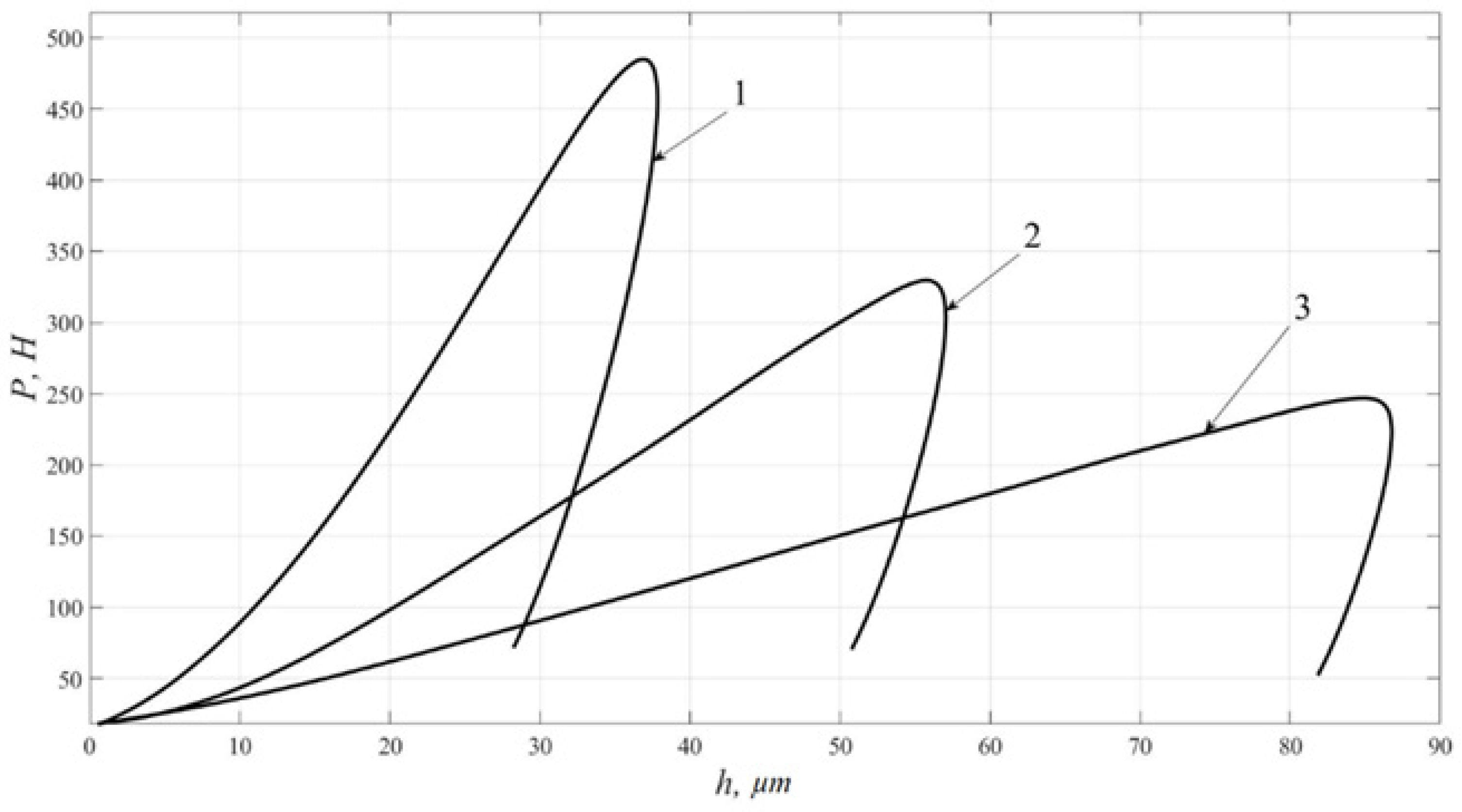
| Test Piece | HV | Maximal Load Pmax, H | Maximal Depth, µm | Residual Depth, µm | Dissipated Energy, mJ | Elastic Energy, mJ | Contact Pressure Pmax/Sres, MPa |
|---|---|---|---|---|---|---|---|
| Al | 30 | 247 | 87 | 81 | 10.8 | 0.7 | 320 |
| Cu | 78 | 330 | 57 | 50 | 10.1 | 1.4 | 689 |
| Fe-C | 206 | 485 | 38 | 28 | 8.7 | 2.8 | 1824 |
Publisher’s Note: MDPI stays neutral with regard to jurisdictional claims in published maps and institutional affiliations. |
© 2022 by the authors. Licensee MDPI, Basel, Switzerland. This article is an open access article distributed under the terms and conditions of the Creative Commons Attribution (CC BY) license (https://creativecommons.org/licenses/by/4.0/).
Share and Cite
Umanskii, A.; Gogolinskii, K.; Syasko, V.; Golev, A. Modification of the Leeb Impact Device for Measuring Hardness by the Dynamic Instrumented Indentation Method. Inventions 2022, 7, 29. https://doi.org/10.3390/inventions7010029
Umanskii A, Gogolinskii K, Syasko V, Golev A. Modification of the Leeb Impact Device for Measuring Hardness by the Dynamic Instrumented Indentation Method. Inventions. 2022; 7(1):29. https://doi.org/10.3390/inventions7010029
Chicago/Turabian StyleUmanskii, Aleksander, Kirill Gogolinskii, Vladimir Syasko, and Artem Golev. 2022. "Modification of the Leeb Impact Device for Measuring Hardness by the Dynamic Instrumented Indentation Method" Inventions 7, no. 1: 29. https://doi.org/10.3390/inventions7010029