1. Introduction
Pumps with progressive cavities allow the circulation of fluids with high viscosity at a constant flow and high pressure [
1,
2,
3]. Among the most used progressive cavity pumps are single screw pumps, consisting of an external helical rotor that rotates eccentrically inside a double internal helical stator [
4,
5]. The active surface of the rotor is a cylindrical helical surface of constant pitch, and the stator, whose active surface is a double helical surface, is also cylindrical and with constant pitch. The stator is usually made of rubber [
6,
7], and the rotor is made of steel, often superficially hardened. The exploitation activity of the pumps with progressive cavities has highlighted the fact that traditional pumps with a rubber stator, which surrounds the rotor, do not allow the existence of an interstice between them, which limits their activity until the stator wears out [
8,
9]. Alternatively, a new class of pumps that do not use elastomers has been developed, in which the rotor and the stator are made of metal, and are used in drilling activities in high temperature wells [
10,
11,
12,
13]. This eliminates the wear and greatly increases the lifetime of the pump for use with viscous, high density, and abrasive liquids, and with liquids containing material in suspension. To ensure proper operation, there must be a space between the rotor and the stator to ensure the leakage of the fluid. If this space is not well defined in the rotor and stator design stage, the efficiency of the pump will be seriously affected. Consequently, dimensional designs and optimizations of the rotor and stator, respectively, using analytical and dynamic simulations of the fluid flow through these pumps, have previously been explored [
14,
15,
16,
17,
18].
The productive functioning of pumps with progressive cavities depends on proper design of the rotor profiles, respecting the technical conditions of their form. The cross-section form of helical pump rotors as ensembles of profiles associated with the rolling centrodes are determined based on the fundamental theorems of the enveloping surfaces (curves) and calculated based on Olivier’s first theorem, the Gohman general theorem, or the Willis theorem (normals method) [
19,
20].
The geometric characteristics of the rotor, namely, the helical surface with long length and rounded profile, determine that it can be processed by volumetric deformation, using tools in the form of profiled rollers with axes parallel to the axis of the processing blank. The algorithm by which the tool profile can be determined contains the following steps: defining the analytical equations in the own reference system of the piece of the generated profile; defining the absolute movements of the piece and the blank during the generating process; defining the relative movements between the piece and the tool; calculation of the trajectories of the points on the piece profile that execute a relative movement towards the tool; defining the condition which allows the determination of these points, called the enveloping condition—these points belong to the trajectory’s family and to the enveloping of that family; and association of the enveloping condition at the equations of the trajectory’s family, a connection that allows the determination of the parametric equations of the tool profile [
21,
22]. The tool’s profiling for generating surfaces of the rotors and the stators of the pump can start either from a physical model or from 3D models obtained by rapid prototyping. In practical activity, the determination of the rotor and the stator form can be undertaken with the help of measuring machines in high precision coordinates when the axial profiles of the generating tools in numerical form are known [
23]. By comparison, these axial and graphical profiles can be determined using facilities of programming and graphical representation environments, such as the CATIA software application [
24].
2. Materials and Methods
2.1. Generating Principle
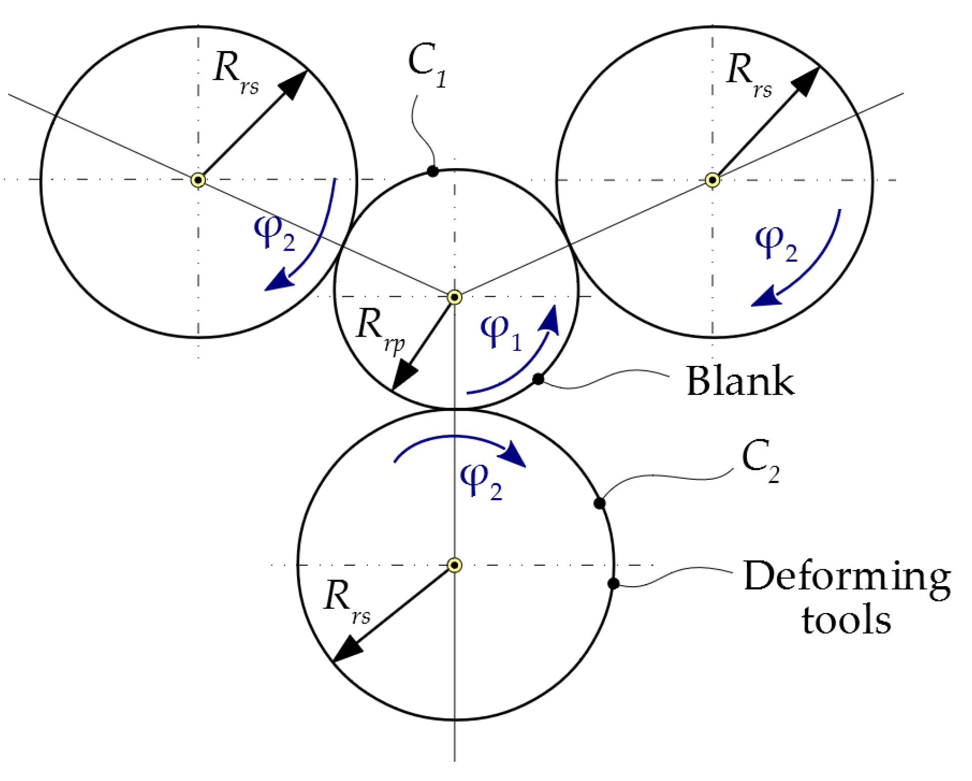
The processing scheme involves the generating of a cylindrical helical surface of constant pitch, using helical deforming tools, with axes parallel to the axis of the deformed screw.
Figure 1 shows the two rolling centrodes:
C1—the centrode of the blank, having the radius
Rrp, and
C2—the centrode of the tool of radius
Rrs.
Note that although three tools are used in the generating process to ensure the balance of large radial loads during processing, it is sufficient to consider a single tool for the tool profiling. The active profile is identical for all three tools being processed simultaneously. In the following, reference will be made to a single generating tool.
The rolling condition between the
C1 and
C2 centrodes has the form:
where, noting
is obtained:
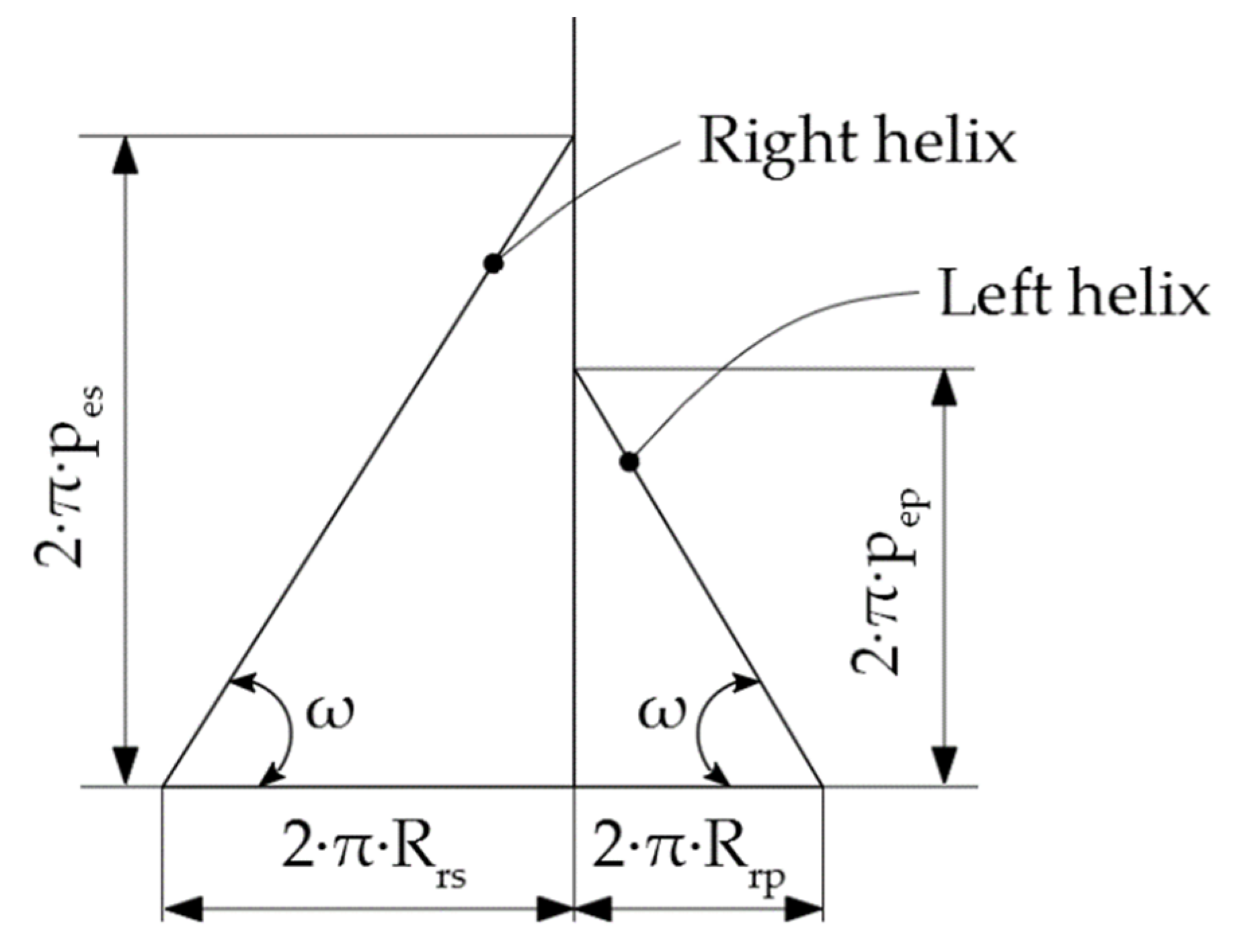
Because the plastic deformation process occurs in the cross-section of the blank, the study of the enwrapping between the two helical surfaces can be performed as for a plane enveloping process in a common plane, perpendicular to the two axes of the tool, with respect to the blank.
To ensure the generation of the active surface of the pump screw, it is necessary that the two helical surfaces, the tool and the blank, have opposite directions and have the same inclination to their own axes on the rolling circles.
Noting the inclination angle of the helix to its own axis with ω, the above condition has the mathematical form given by Equation (3):
where
pet represents the helical parameter of the tool and
pep is the helical parameter of the piece; also see
Figure 2.
2.2. The Equations of the Active Surface of the Rotor
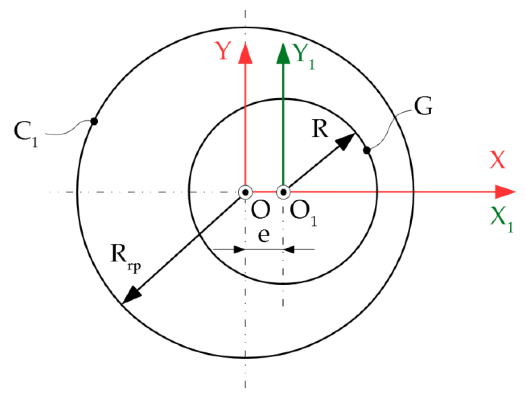
2.2.1. Cross-Section of the Screw
The cross-section of the active surface of the rotor is a circle of radius R, eccentric to the C1 centrode, with e size.
The reference systems used for the active surface determination are presented in
Figure 3.
To solve the profiling problem of the generating tool, the following reference systems are used: xyz is a fixed reference system, with its origin in the center of the blank centrode and the z-axis superimposed on the rotational axis of the blank; x1y1z1 is a fixed reference system, with its origin in the center of the tool centrode and the z1 axis superimposed on the rotational axis of the tool; XYZ is a mobile reference system, joined with the blank—this system performs a rotational movement with the blank around the axis; ξηζ is a mobile reference system, joined with the tool—the axis and the system has a rotational movement around it.
The generating profile of the active helical surface of the screw, the surface
Σ, is given by the equations:
2.2.2. Helical Surface
The helical movement of the
G-profile, the
Z-axis, and the
pep helical parameter, generates the
Σ surface:
By development, the following is obtained:
2.3. Determination of the Virtual Pole Position
The determination of the virtual pole position is made from the condition that the normal to the profile of the piece intersects the centrode associated with it.
The profile of the piece has the equations given by (4), so its direction will be:
with
and
resulting in:
In the current point, the normal to the profile can be written as:
with variable scalar
λ.
By development, the following is obtained:
The
C1 centrode has the equations:
According to the virtual pole method [
17,
18], it is located at the intersection of the normal at the
G profile at the current point with the centrode associated with the piece. The intersection condition becomes:
By removing the parameter
λ from Equation (12), the following is obtained:
2.4. Contact Curve Determination
The determination of the contact curve equations is undertaken by applying the absolute movement of the piece (the angle rotation φ1 around the origin O) to the current point.
When the current point passes through the entire G profile, the curve obtained represents the contact curve.
If the current point is denoted with
T, its coordinates in the own system of the piece will be:
When β goes through the entire domain of values, from 0 to the current point goes through the entire contact curve.
At some point, the coordinates of the current point in the fixed system
xyz will be given by:
which can be developed as:
2.5. The Determination of the Cross-Section of the Active Surface
The determination of the cross-sectional profile of the active surface of the helical tool is undertaken by applying a movement corresponding to the absolute movement of the tool to each point determined on the contact curve.
The determination of the cross-section can be made if the problem is treated as a plane enwrapping problem, in a plane perpendicular to the rotational axes of the two elements, the X-axis of the blank, and the ζ axis of the tool.
The absolute movement of the tool is given by the transformation:
Between the movement of the tool and that of the blank, Equation (2) is respected by the rolling condition.
Knowing the coordinates of the points on the contact curve in the
xyz system, in the absolute movement of the
ξηζ system, these are given by the following transformations:
where:
where:
By development, the following is obtained:
The cross-section of the tool is obtained by intersecting the active surface with a plane perpendicular to the
ζ axis,
3. Results
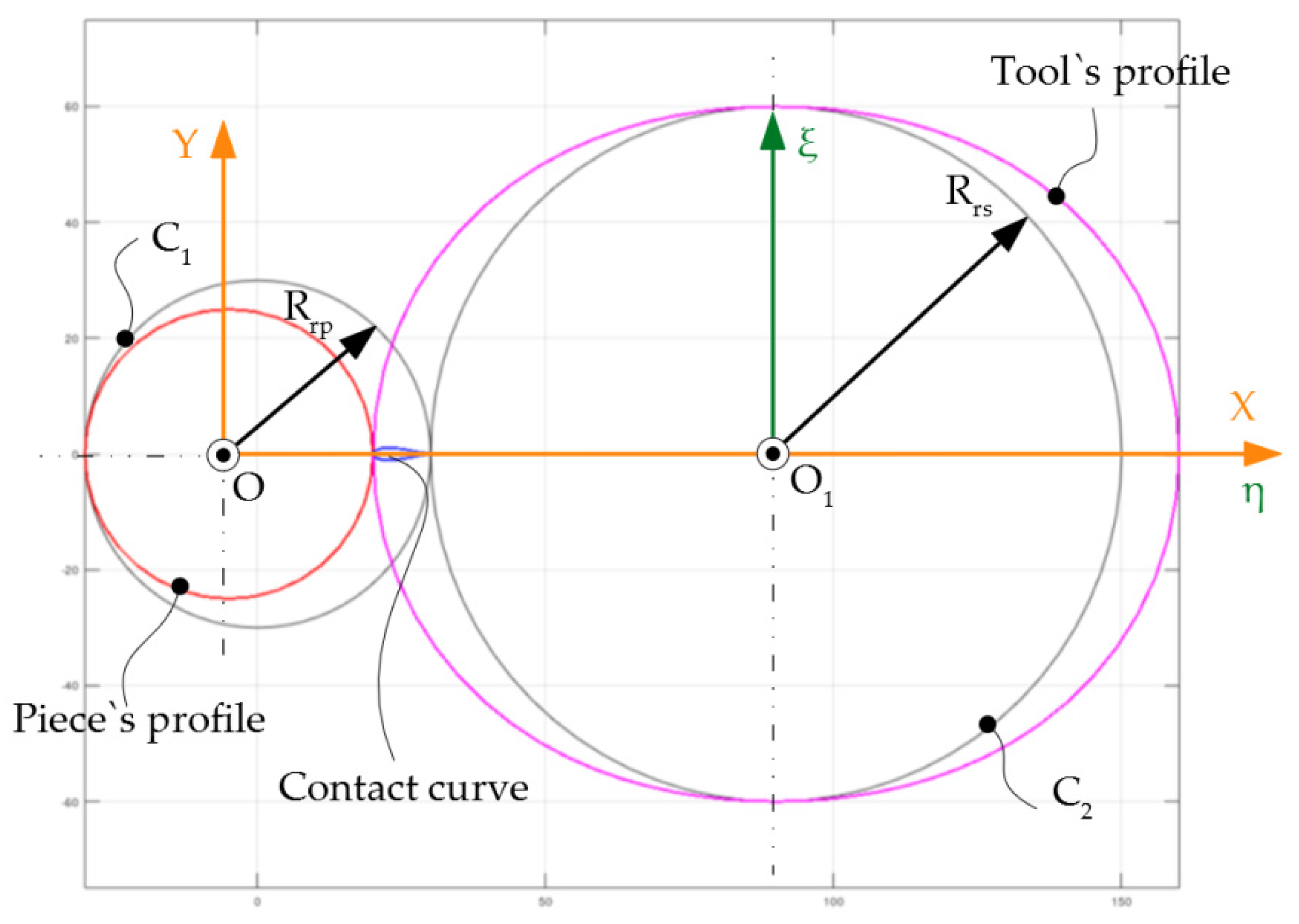
A numeric application was developed for the following values: Rrp = 30 mm; Rrs = 60 mm; R = 25 mm; e = −5 mm; the piece’s pitch.
The numerical application was undertaken using the GNU Octave software program, a computer application for performing numerical calculations that is generally compatible with the MATLAB program.
The values table of the tool’s profile and the contact curve are presented in
Table 1 and graphically in
Figure 4.
Figure 4 shows an axial view of the piece profile, tool profile, and the contact curve (treated as a plane problem). In reality, the enwrapping surfaces are helical (three-dimensional) surfaces and
Table 1 shows the 3D coordinates of the points belonging to the contact curve in the two reference systems: the tool system (
ξηζ) and the piece system (
XYZ).
4. Conclusions
This paper presented an algorithm for profiling the rollers for processing the helical surfaces of a pump rotor with progressive cavities.
The algorithm is based on the virtual pole method, which is a variant of the normal theorem.
The new form of this theorem allows the determination of the enwrapping equations of a family of profiles generated in the rolling movement of two centrodes, eliminating the need to write the equations of relative movements between the generating profile and the profile to be generated. This eliminates an important source of possible errors and greatly simplifies the process of calculating the profile of the generating tool.
In future work, the aim is to apply the “virtual pole” method for the study of surfaces obtained by computer-aided inspection, using a three-dimensional measurement technique, namely, the reverse engineering concept. In other words, the surfaces will be scanned, using equipment based on a 3D optical scanner, without physical contact, existing within the Dunarea de Jos University of Galati, Faculty of Engineering. This device is an Atos Core, produced by GOM GmbH (Schmitzstraße 2, 38122, Braunschweig, Germany), which uses a modern and innovative technology for the fully automated inspection and measurement of the pieces. The scanning accuracy with the GOM 3D scanner is very high, almost entirely covering the surface of the pieces and providing all the details of the measured piece with great precision. The GOM 3D scanning system also ensures the identification of the manufacturing problems, based on the possibility of comparing the theoretical and real geometries of the obtained pieces. Therefore, using this scanning system, the geometric generation errors of surfaces can be estimated based on the “virtual pole” theorem.
Author Contributions
Conceptualization, N.B. and N.O.; methodology, V.-G.T.; software, V.-G.T.; validation, N.B., V.-G.T. and N.O.; formal analysis, N.O.; investigation, N.B.; resources, N.B.; data curation, V.-G.T.; writing—original draft preparation, G.-A.M.; writing—review and editing, G.-A.M.; visualization, N.B.; supervision, N.O.; project administration, N.B.; funding acquisition, G.-A.M. All authors have read and agreed to the published version of the manuscript.
Institutional Review Board Statement
Not applicable.
Informed Consent Statement
Not applicable.
Acknowledgments
The results of this work will be also presented to the 9th edition of the Scientific Conference organized by the Doctoral Schools of Dunarea de Jos University of Galati (SCDS-UDJG)
http://www.cssd-udjg.ugal.ro/ (accessed on 13 May 2021) that will be held on 10th and 11th of June 2021, in Galati, Romania.
Conflicts of Interest
The authors declare no conflict of interest.
References
- Lehman, M. Progressing cavity pumps in oil and gas production. World Pumps 2004, 2004, 20–22. [Google Scholar] [CrossRef]
- Dunn, L. Progressing Cavity Pumping Systems Overview with a Focus on Coal Seam Gas Applications. Available online: https://fdocuments.in/document/progressing-cavity-pumping-systems-overview-with-a-focus-on-.html (accessed on 19 April 2021).
- Chaudhary, P. Review on Optimization of PC-Pumps Installation in CBM Reservoirs and Troubleshooting Problems Faced By Them during Dewatering Imperial. J. Interdiscip. Res. 2016, 2, 1150–1155. [Google Scholar]
- Progressive cavity pumps, S.C.; Confind, S.R.L. Câmpina, România. Available online: http://www.confind.ro/pompe_cavitati_progresive.html (accessed on 19 April 2021).
- Wittrisch, C.; Cholet, H. Progressing Cavity Pumps Oil Well Production Artificial Lift; Editions Technip: Paris, France, 2013. [Google Scholar]
- Liang, Y.; Cao, G.; Shi, G.; Wang, G.; Li, J.; Zhao, Y. Progressing cavity pump anti-scaling techniques in alkaline-surfactant-polymer flooding in the Daqing Oilfield. Pet. Explor. Dev. 2011, 38, 483–490. [Google Scholar] [CrossRef]
- Al Naboulsi, M.I.; Antonescu, N.N.; Dinita, A.; Morosanu, M. Tribological Characterization of Some Elastomers Used at Progressive Cavity and Piston Pumps. In Proceedings of the MATEC Web of Conferences 2020, 318, 7th International Conference of Materials and Manufacturing Engineering (ICMMEN), Thessaloniki, Greece, 2–3 July 2020. [Google Scholar]
- Wang, H.; Wang, S.; Lv, H. The effects of temperature on the mechanical and tribological properties of progressing cavity pump NBR stator rubber. J. Mater. Sci. 2016, 22, 308–312. [Google Scholar] [CrossRef] [Green Version]
- Merey, S. Comparison of Sucker Rod Pump and Progressive Cavity Pump Performances in Batı Raman Heavy Oil Field of Turkey. Celal Bayar Univ. J. Sci. 2020, 16, 191–199. [Google Scholar]
- Arredondo, M.; Caballero, D.; Morety, R.; Delgado, A.; Ortegano, B.J. All Metal PCP Experiences in Orinoco Belt; SPE Artificial Lift Conference & Exhibition-North America: Houston, TX, USA, 2014. [Google Scholar]
- Bybee, K. First Metal-PCP SAGD Field Test Shows Promise for Heavy-Oil Hot Production. J. Pet. Technol. 2015, 60, 70–73. [Google Scholar] [CrossRef]
- Li, M.; Jiang, D.; Guo, H.; Meng, F.; Yu, M.; Du, W.; Zhang, G. Study on clearance optimization of all-metal screw pumps: Experiment and simulation. Mechanika 2017, 23, 735–742. [Google Scholar] [CrossRef] [Green Version]
- Zhang, H.; Wu, X.; An, Y. Study on Speed and Clearance Optimization of All-Metal Progressing Cavity Pumps: Experiment and Simulation. ACS Omega 2020, 5, 19533–19540. [Google Scholar] [CrossRef] [PubMed]
- Zhou, D.; Yuan, H. Design of Progressive Cavity Pump Wells. In SPE Progressing Cavity Pumps Conference; Society of Petroleum Engineers: Houston, TX, USA, 2008. [Google Scholar] [CrossRef]
- Ceballos, J.B.; Vivas, O.A. Mathematical model of controllers for progressive cavity pumps. Rev. UIS Ing. 2019, 18, 17–30. [Google Scholar] [CrossRef]
- Nguyen, T.; Tu, H.; Al-Safran, E.; Saasen, A. Simulation of single-phase liquid flow in progressing cavity pump. J. Pet. Sci. Eng. 2016, 147, 617–623. [Google Scholar] [CrossRef]
- SH Lee, S.H.; Kwak, H.S.; Han, G.B.; Kim, C. Design of Gerotor Oil Pump with 2-Expanded Cardioids Lobe Shape for Noise Reduction. Energies 2019, 12, 1126. [Google Scholar]
- Om, I.L.; Ryo, S.I.; Kim, C.Y. Calculation for cross section and area efficiency of progressing cavity pump with hypotrochoidal multilobe using the differential geometric envelope approach. J. Pet. Sci. Eng. 2018, 171, 211–217. [Google Scholar] [CrossRef]
- Litvin, F.L. Theory of Gearing, Reference Publication 1212; NASA, Scientific and Technical Information Division: Washington, DC, USA, 1984.
- Oancea, N. Surfaces Generation through Winding, Vol. I-III; Galati University Press: Galati, Romania, 2004. [Google Scholar]
- Costin, G.A.; Teodor, V.G.; Oancea, N. Virtual Pole Method-Alternative Method for Profiling Tools Which Generate by Enwrapping. Ann. Dunarea Jos Univeristy 2019, 5, 31–34. [Google Scholar]
- Teodor, V.G.; Costin, G.A. Virtual Pole Method-Alternative Method for Profiling Rack Tools. Ann. Dunarea Jos Univeristy 2019, 5, 5–8. [Google Scholar]
- Popa, C.L.; Teodor, V.G.; Baroiu, N.; Oancea, N. Side Mill Tool Profiling for Generation of Helical Surfaces Determined by Reverse Engineering. Appl. Mech. Mater. Eng. Solut. Technol. Manuf. 2014, 657, 28–32. [Google Scholar] [CrossRef]
- Berbinschi, S.; Teodor, V.G.; Baroiu, N.; Oancea, N. Profiling Methodology for Side Mill Tools for Generation of Helical Compresor Rotor Using Reverse Engineering. Ann. Dunarea Jos Univ. Galati Fascicle V Technol. Mach. Build. 2011, 2, 111–116. [Google Scholar]
| Publisher’s Note: MDPI stays neutral with regard to jurisdictional claims in published maps and institutional affiliations. |
© 2021 by the authors. Licensee MDPI, Basel, Switzerland. This article is an open access article distributed under the terms and conditions of the Creative Commons Attribution (CC BY) license (https://creativecommons.org/licenses/by/4.0/).


