Article

A Robust Interval Type-2 Fuzzy Logic Controller for Variable Speed Wind Turbines Based on a Doubly Fed Induction Generator

by
Ahmed Vall Hemeyine
1,*,
Ahmed Abbou
1,
Anass Bakouri
1,
Mohcine Mokhlis
1 and
Sidi Mohamed ould Mohamed El Moustapha
2
1
Mohammadia School of Engineers (EMI), Mohammed V University in Rabat, 6203 Rabat, Morocco
2
Faculty of Science and technology, Alasriya University in Nouakchott, BP 880 Nouakchott, Mauritania
*
Author to whom correspondence should be addressed.
Inventions 2021, 6(2), 21; https://doi.org/10.3390/inventions6020021
Submission received: 22 January 2021 / Revised: 19 March 2021 / Accepted: 19 March 2021 / Published: 24 March 2021
(This article belongs to the Special Issue New Advances and Challenges in Wind Energy Extraction II)

Abstract

:
This paper presents an implementation of a new robust control strategy based on an interval type-2 fuzzy logic controller (IT2-FLC) applied to the wind energy conversion system (WECS). The wind generator used was a variable speed wind turbine based on a doubly fed induction generator (DFIG). Fuzzy logic concepts have been applied with great success in many applications worldwide. So far, the vast majority of systems have used type-1 fuzzy logic controllers. However, T1-FLC cannot handle the high level of uncertainty in systems (complex and non-linear systems). The amount of uncertainty in a system could be reduced by using type-2 fuzzy logic since it offers better capabilities to handle linguistic uncertainties by modeling vagueness and unreliability of information. A new concept based on an interval type-2 fuzzy logic controller (IT-2 FLC) was developed because of its uncertainty management capabilities. Both these control strategies were designed and their performances compared for the purpose of showing the control most efficient in terms of reference tracking and robustness. We made a comparison between the performance of the type-1 fuzzy logic controller (T1-FLC) and interval type-2 fuzzy logic controller (IT2-FLC). The simulation results clearly manifest the height robustness of the interval type-2 fuzzy logic controller in comparison to the T1-FLC in terms of rise time, settling time, and overshoot value. The simulations were realized by MATLAB/Simulink software.

1. Introduction

Recently, renewable energies have experienced strong progress in their development thanks to their significant contribution to minimizing polluting CO2 emissions and avoiding the high cost of energy production induced by the conventional energy sources [1]. Therefore, the use of renewable energies is the only way to reduce the dependence on fossil fuel energies (coal, oil, natural gas, etc.) that generate carbon dioxide (CO2) and other polluting gases. Among the renewable energy sources are solar energy, hydropower, and wind energy [2].
For its profitability, cleanliness, and inexhaustibility, wind power has become one of the most promising and important renewable energy technologies in the world. Indeed, this renewable energy respects the environment and helps to avoid or, in some cases, minimize using production sources that produce unwanted carbon dioxide (CO2) [3].
Recently, fixed speed wind turbines have been replaced by variable speed wind turbines. Indeed, operating at variable speed allows the wind turbine to extract the maximal power from wind. Four types of generators can be used with the variable speed wind turbines; there is the squirrel cage induction generator (SCIG), the dual field induction generator (DFIG), the permanent magnet synchronous generator (PMSG), and the wound field synchronous generator (WFSG) [4,5].
The DFIG has become widely used due to its efficiency, minimum power losses, robustness, ease of control, reduced cost, and ability to work at a speed that varies by ±33% around the synchronous speed. Moreover, this generator requires only slight maintenance [6]. The studied system is illustrated in Figure 1a.
The presence of wind does not ensure production of a high quality of wind energy without using an adequate control strategy. In fact, that motivated the researchers to propose and develop many control strategies able to obtaining a high quality of wind energy. In the literature, there are control strategies such as the vector control concept (voltage orientation or stator flux) combined with various controllers (such as proportional-integral controllers). Unfortunately, when the internal parameters of the machine change, this control strategy loses his robustness [6,7].
Conventional proportional-integral (PI) controllers are the most commonly used in the control strategy of wind energy conversion system due to their simple implementation and deliver a good performance under normal conditions. However, under challenging operating conditions such as parameter variations, and the wind disturbance effect, the control strategies based on the PI controller do not give a satisfactory performance in terms of accuracy [8].
However, to solve tracking trajectory and stabilization problems, and to adapt for parameter variations of the DFIG-based WECS, many controllers have been developed in nonlinear form, such as the sliding mode controller, the backstepping sliding mode controller (BSMC), and the fuzzy logic controller [9].
The sliding mode controller is most studied in the literature [9,10]. It is a robust nonlinear controller that can reject uncertainty and perturbation, but the major drawback of the sliding mode controller is the chattering phenomena. To solve this problem, many solutions are presented in the literature, such as the high order sliding mode, and the backstepping sliding mode controller (BSMC) that consists of two nonlinear controllers (backstepping and sliding mode). Despite the tracking performance of the BSMC controller, it remains complex to implement [10].
In recent years, many researchers focused on improvements of the control strategy based on fuzzy logic. The first fuzzy theory was proposed and discussed by Prof. Lotfi Aliasker Zadeh [9,11]. Thus, the classical fuzzy logic called today fuzzy logic type 1 has been generalized to a new fuzzy logic called fuzzy logic type 2. Now we are working with a new type of fuzzy logic controller called type 2. In this paper, we propose to use an interval type-2 fuzzy logic controller (IT2-FLC) in order to overcome the limitations of fuzzy logic type 1 previously developed.
A T1-FLC has successfully been applied to control a DFIG-based WECS. This controller presents a better performance compared with the previous controllers. However, the main inconvenience of T1-FLC is the limitation in the face of the significant uncertainties in the system parameters [12].
This limitation is due mainly to the use of simple membership functions (MFs) characterized by the T1-FLC controller. To manage the uncertainties, we used an IT2-FLC controller to control a DFIG-based WECS. This controller is characterized by using the other three-dimensional MFs for the purpose of ensuring an additional degree of freedom to manage the uncertainties.
Finally, the IT2-FLC controller is compared with the T1-FLC controller in order to show its tracking performance (rapidity and accuracy) and also to show its robustness against the rapid changes of the reference signal.
This work is structured as following. Section 2 discusses the modeling of the DFIG as well as the wind energy conversion system, the MPPT control strategy and the pitch control. Section 3 discusses the simulation results and demonstrates the performance and robustness of the proposed interval type-2 fuzzy controller (IT2-FLC) and also presents comparison between this controller and the conventional type-1 fuzzy controller (T1-FLC). The last section is devoted to the conclusion.

2. WEC System Model

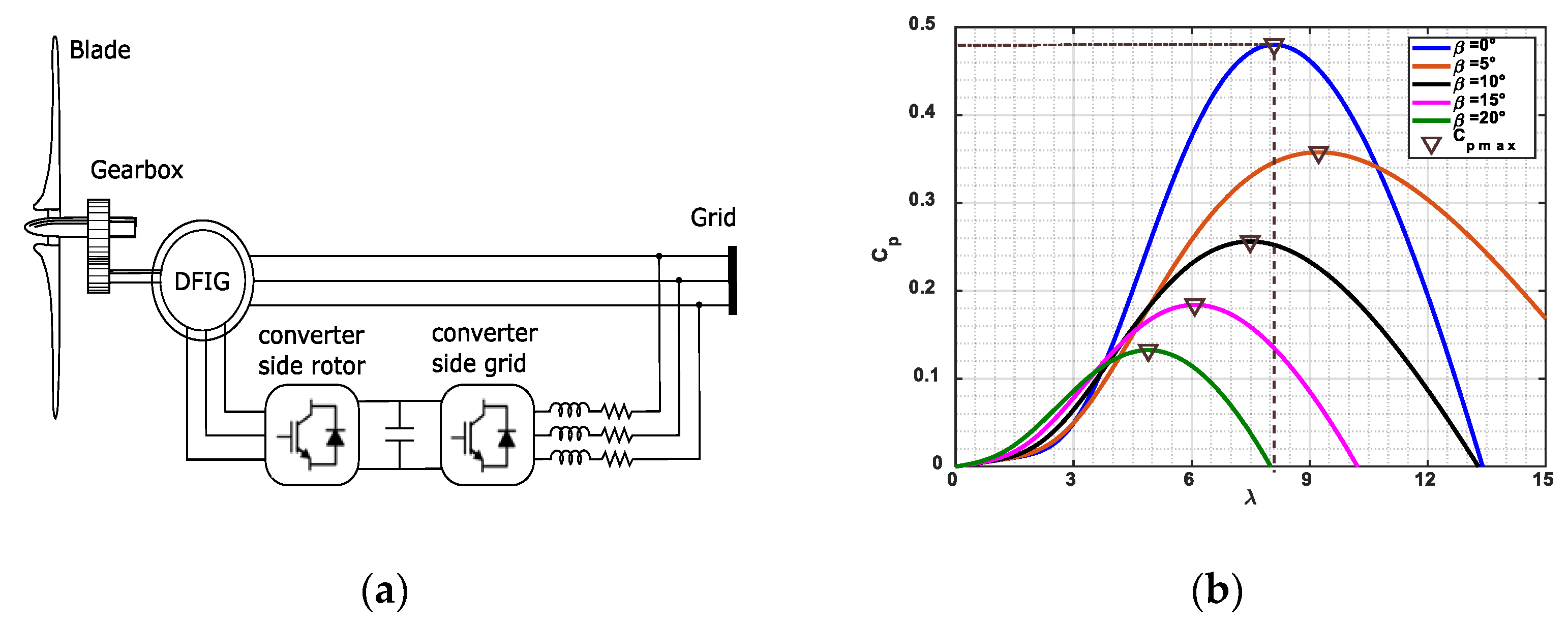
2.1. Modeling of the Wind Turbine

The following equation describes the aerodynamic power that can be extracted from the wind [13].
P w = 0.5 C p λ , β ρ π R 2 V w 3
where ( ρ ) is the air density (1.225 kg/m3), ( R ) presents the turbine blades’ radius, ( λ ) is the speed ratio, ( V w ) is the speed of wind (m/s), while ( C p ) presents the power coefficient that depends on the pitch angle ( β ). The parameters λ and C p can be expressed as described in the following equations:
λ = R Ω t V w
C p λ ,   β = C 1 C 2 λ i C 3 β C 4 exp C 5 λ i + C 6 λ
with
C 1 = 0.5176 ,   C 2 = 116 ,   C 3 = 0.4 ,   C 4 = 5 ,   C 5 = 21   and   C 6 = 0.0068
where   1 λ i = 1 λ + 0.08 . β 0.035 β 3 + 1
Figure 1b illustrates curves of the power coefficient ( C p ) as a function of ( λ ) obtained for various cases of pitch angle β and under variable speed. Here, C p m a x = 0.48 presents the maximal value of C p λ ,   β obtained for β = 0 and λ o p t = 8.1 .
In order to be able to produce power from wind energy, it is essential to adapt the wind turbine to the DFIG. For this reason, the gearbox (with a gear ratio G ) is added in the studied system [14]. The mechanical speed and the generator torque can be expressed as described in Equations (5) and (6).
Ω m = G Ω t
T e m = T t G
Effectively, the MPPT control strategy is essential for extracting maximal power for an average and low wind speed. The main aim behind using this control strategy is to maximize the power captured by the turbine rotor. However, to achieve this objective, it is necessary to control the electromagnetic torque T e m of the DFIG so as to fix the DFIG rotation speed at the rotation speed reference [14,15]. Indeed, this latter can be expressed as described in the following equation:
Ω t o p t = V w λ o p t R
In this study, the maximal speed ratio is supposed equal to the optimal value C p m a x = 0.48 which, as discussed previously, is obtained considering λ o p t = 8.1 and assuming that β is equal to 0, which allows extracting the maximum of power. So, under these conditions, the maximum mechanical power that can be extracted from the wind is expressed as described in the following form:
P m e c = π ρ R 5 C p m a x Ω m e c 3 2 λ o p t 3
The reference torque T e m r e f is given by the following equation:
T e m r e f = π ρ R 5 C p m a x Ω m e c 2 2 λ o p t 3
If the wind speed is too high, the turbine rotation speed has to be limited to a maximum value in order to avoid the possible damage in the turbine structure. For this, the system controller, which is the pitch control, is used. As a result, the electrical energy produced by the wind turbine can be kept constant and equal to the nominal value.

2.2. Modeling of DFIG

The model of the DFIG is described in the ( d , q ) reference frame [16] by the following set of equations.
V s d = R s I s d + d φ s d d t ω s φ s q V s q = R s I s q + d φ s q d t + ω s φ s d V r d = R r I r d + d φ r d d t ω r φ r q V r q = R r I r q + d φ r q d t + ω r φ r d
The rotor and stator flux are expressed in the following forms:
φ s d = L s I s d + L m I r d φ s q = L s I s q + L m I r q   φ r d = L r I r d + L m I s d φ r q = L r I r q + L m I s q
where V r is rotor voltage, V s is stator voltage, is rotor current, I s   is stator current, R s : is stator resistance, R r is rotor resistance, L r is rotor leakage inductance, L s is stator leakage inductance. L m is mutual inductance, ω s is stator pulsation.
T e m = P M L s I r d φ s q I r q φ s d
The system mechanical equation is:
J d Ω m d t = T m T e m f Ω m
Moreover, to be able to control the DFIG easily, we will achieve independent control of active and reactive power by the stator flux orientation. The principle is to align the stator flux along the d-axis of the rotating frame. For medium and high-power machines used in wind energy conversion systems, the stator resistance R s can be neglected; the electrical equations of the DFIG model are expressed as below:
φ s d = φ s   And   φ s q = 0
In addition, the stator voltage equations are reduced to:
V s d = 0 V s q = V s = ω s φ s
The active and reactive powers at the stator side are written as
P s = V s d I s d + V s q I s q = V s L m L s I r q Q s = V s q I s d V s d I s d = V s 2 ω s L s V s q L m L s I r d
Thereafter, we establish the equations showing the relationship between the rotor voltages and rotor currents:
V r d = R r i r d + L r σ d I r d d t g L r σ ω s I r q V r q = R r i r d + L r σ d I r q d t + g ω s L r σ I r d + L m V s L s
With the leakage coefficient σ is given by:
σ = 1 L m 2 L r L s
Figure 2 illustrates the global scheme of the proposed control strategy. As can be seen, the rotor side converter is controlled to regulate the active and reactive power to specific references. Effectively, there are two controllers for regulating the rotor currents to their reference values; the first one acts on the D axis while the second one acts on the Q axis. Additionally, two types of controller are investigated, the interval type-2 fuzzy logic (IT2-FLC) and the classic (T1-FLC).

2.3. Description of Fuzzy Logic SETs

To overcome the problems of the classical control method such as, these performances are assigned when the real machine parameters differ from those values used in the control system. We opted for using a fuzzy logic controller to control the behaviors of the DFIG wind turbine and mainly to regulate active and reactive power.

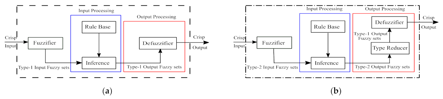
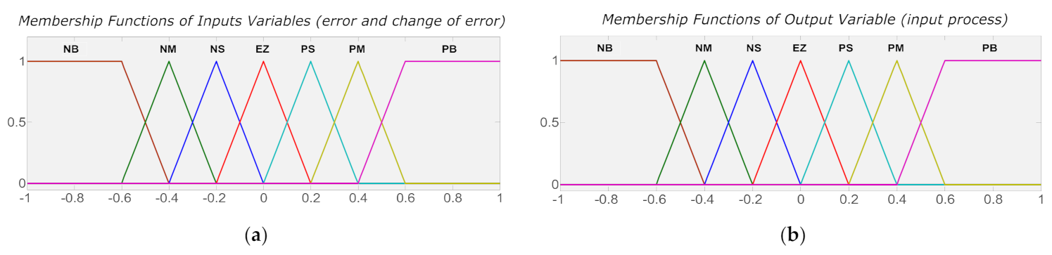
2.3.1. Overview of Type-1 Fuzzy Logic Sets (T1-FLS)

A type-1 fuzzy set in the universe X is characterized by a membership function μ A x taking values on the interval 0,1 and can be represented as a set of ordered pairs of an element. The membership degree of an element to the set is defined by the following Equation (19):
A = x , μ A x | x X
where                                                                                       μ A : X 0,1
In this definition, μ A x represents the membership degree of the element x X to the set A . In this work we are going the use the following notation:
A x = μ A x                                               For   all                             x X

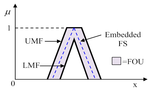
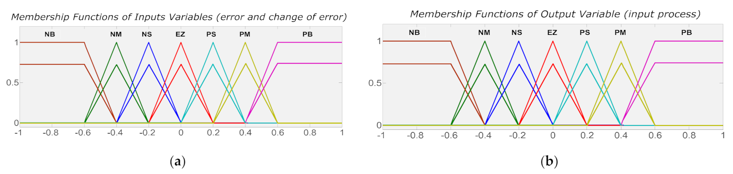
2.3.2. Basic Concepts of Interval Type-2 Fuzzy Logic Sets (IT2-FLS)

According to the definition of Zadeh, A type-2 fuzzy sets are the generalized forms of type-1 fuzzy sets [17,18]. An interval type-2 fuzzy set denoted as A ˜ is characterized by a type-2 membership function μ A ˜ x , u and can be described as:
A ˜ = x , u , μ A ˜ x , u | x X , u J x u 0,1
in which
x X     ,   u J x 0,1                     And                 0 μ A ˜ x , u 1
  A ˜ can be also expressed as
A ˜ = x X u J x μ A ˜ x , u / x , u , J x 0,1
where x X u J x denote union over all admissible input variables x and u .
Here, X is the primary domain of the input variable,   x is the value of the input variable, u is the primary grade of a type-2 fuzzy set, and J x is called the primary membership of a type-2 fuzzy set of x and μ A ˜ x , u is the secondary membership function equal to 1 .
Another expression for A ˜ is
A ˜ = x X u J x 1 / μ A ˜ x , u , J x 0,1
A ˜ : X a , b : 0 a b 1                        
The union of all the primary memberships represents the uncertainty about A ˜ , which is called the footprint of uncertainty F o u of A ˜ as shown in Figure 3, i.e., [19].
F o u A ˜ = X   J x = x , u : u J x 0,1
The F o u of A ˜ is bounded by two type-1 MFs called upper membership function (UMF) and lower membership function (LMF) as shown in Figure 3. The LMF and UMF are denoted as μ A ˜ x and μ ¯ A ˜ x , respectively, and are defined as follows:
μ _ A ˜ x = F o u A ˜ _ , x X
μ ¯ A ˜ x = F o u A ˜ ¯ , x X
Note that J x is an interval set; i.e.,
J x = x , u : u μ ¯ A ˜ x , μ _ A ˜ x
An embedded fuzzy set A ˜ e for a continuous universe of discourse x and u is described as
A ˜ e = x X 1 / u x , u J x
The set A ˜ e is embedded in A ˜ in such a way that the secondary membership functions (MFs) are always one at each value of x . A large number of such embedded type-1 fuzzy sets (T1-FSs) are combined to form the type-2 fuzzy set (T2-FS), which enables the detailed description of the analytical control surface; the addition of the extra levels of classification gives a much smoother control surface and response. The T2-FS can be considered as a combination of many different type-1 fuzzy sets where each (T1-FS) is embedded to form the F o u [20].

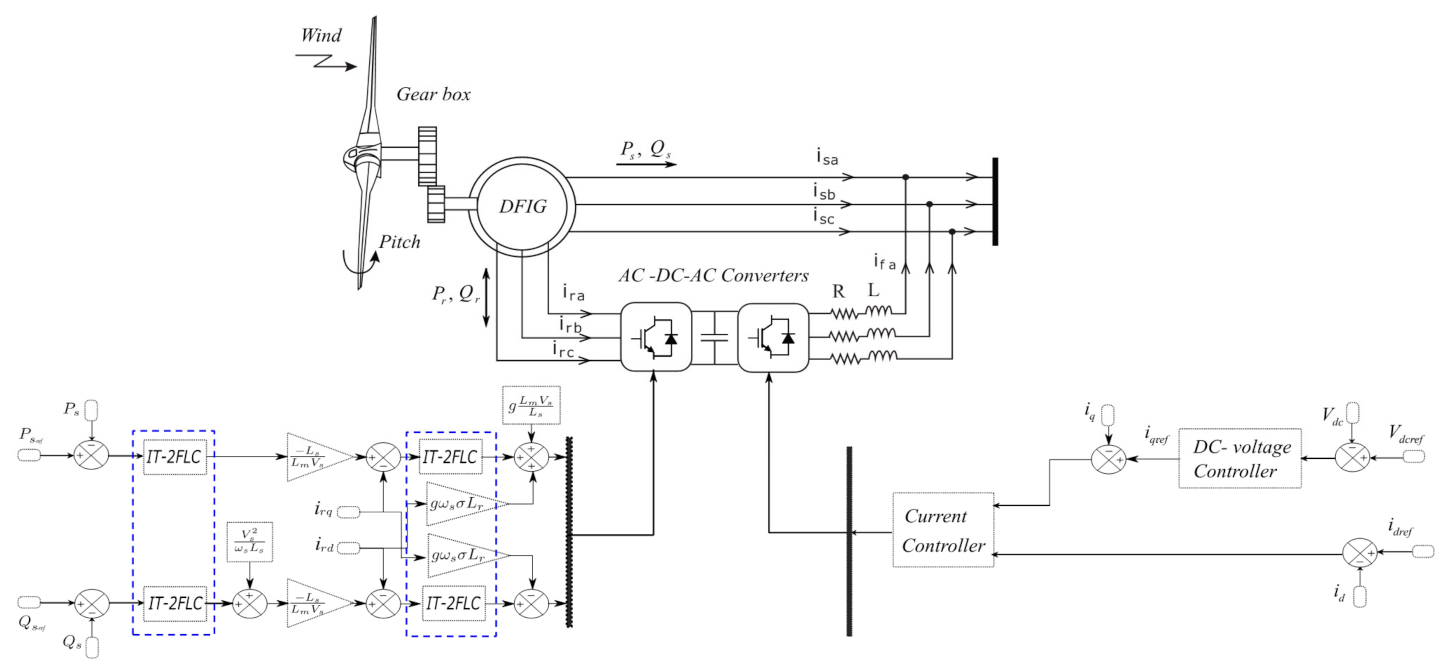
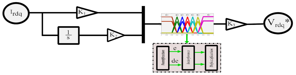
2.3.3. Control of Doubly Fed Induction Generator Using IT2-FL

The type-2 fuzzy logic controller (IT2-FLC) is very useful in circumstances where we need to take into consideration the different uncertainties as the real machine parameters change, and as the controller for a variable speed wind turbine-based on DFIG is used mainly to regulate active and reactive power exchanged with an electrical network. To control a DFIG-based wind energy conversion system easily, we used the independent control of active and reactive power using the stator flux orientation. In the control diagram, the classical rotor currents controllers were replaced by an IT 2-FLC [21].
The DFIG-based WEC system model was simulated first using a conventional T1-FLC and then an IT2-FLC. The rule base was the same for both type-1 and type-2 fuzzy logic controllers. The fuzzy control strategy is based on a human operator experience to interpret a situation and initiate its control action. The global scheme of the control of the DFIG-based WEC system using an IT2-FLC and T1-FLC is presented in Figure 2.
The core of the type-2 fuzzy logic controller (IT2-FLC) was the type-1 fuzzy logic controller (T1-FLC), as Figure 4 shows. The IT2-FLC was constituted of four functional blocks, the three blocks of type-1 fuzzy and a fourth functional block that ensured the type reducer transformed a type-2 fuzzy set into a type-1 fuzzy set [22]. The structures of IT2-FLS and T1-FLS are shown in Figure 4a,b, respectively.
-
The fuzzifier stage is used to translate inputs (real values) to fuzzy values.
-
The inference (reasoning) stage consists of two blocks, the rules base and the inference engine; it works the same way as for type-1 fuzzy systems, except the antecedents’ fuzzy sets and the consequent are represented by type-2 fuzzy sets.
-
The process consists of combining the rules base to produce a mapping from input to the output type-2 fuzzy set [23]. It is necessary to calculate the intersection, union and composition of type-2 relations in order to realize this mapping.
-
The type reducer is used to convert all type-2 fuzzy sets into a type-1 fuzzy set on the output. There are several methods to calculate the reduced set, such as joint center, center of sums, height, and center joint, among others [24].
-
The defuzzification stage translates an output into precise values.
A comparison between a T1-FLC and an IT2-FLC is given in the following.
In this paper, seven triangular membership functions were chosen for the IT2-FLC and T1-FLC, because these membership functions are easier to implement in practical hardware, used as the inputs and outputs, which are also shown in Figure 5 and Figure 6, respectively. The maximum and minimum values of the universe of discourse for all inputs and output were −1 to +1 [25].
The controller inputs are error (e) and its derivative (de). The only output of the controller is the control signal (u). Each input and output contains seven membership functions, two trapezoidal and five triangular [26]. Input and output membership functions (MFs) of the T1-FLC and IT2-FLC are demonstrated in Figure 5 and Figure 6, respectively.
For the optimal performance of the controllers, a 49-rule base was designed for the IT2-FLC and T1-FLC, as shown in Table 1. Referring to this table, NL defines the negative large. NM and NS are the negative medium and the negative small, respectively. ZR is zero while PL , PM , and PS are the positive large, positive medium, and the positive small, respectively. The rule base is the core part of the IT2-FLC and T1-FLC design which is based on process dynamics, experts’ knowledge, and experience.
The IT2-FLC was modeled on the MATLAB environment as depicted in Figure 7 and the parameters of the type-2 fuzzy ( k 1 , k 2 , k 3 ) were determined by the trial-and-error method [27].

3. Simulation Results

The control strategy proposed in this study was evaluated and compared in order to test its tracking performances under MATLAB software. The system parameters are listed in Table 2 and Table 3.

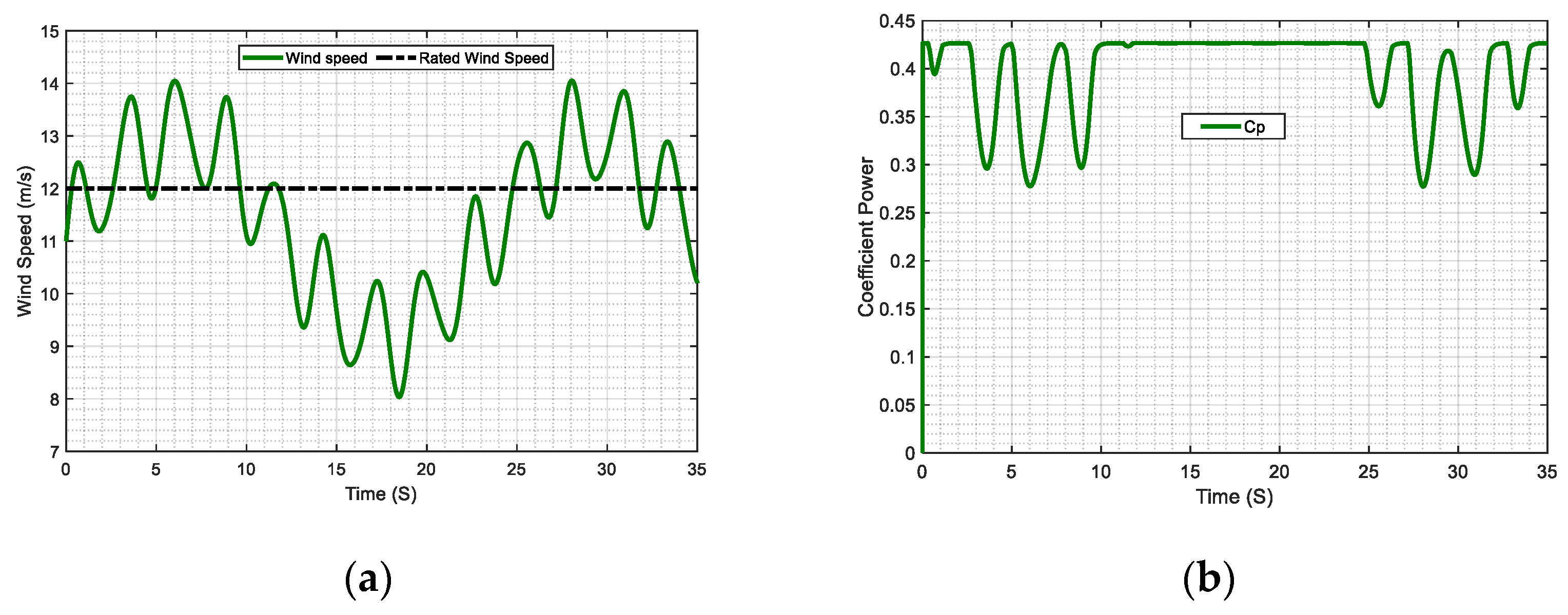
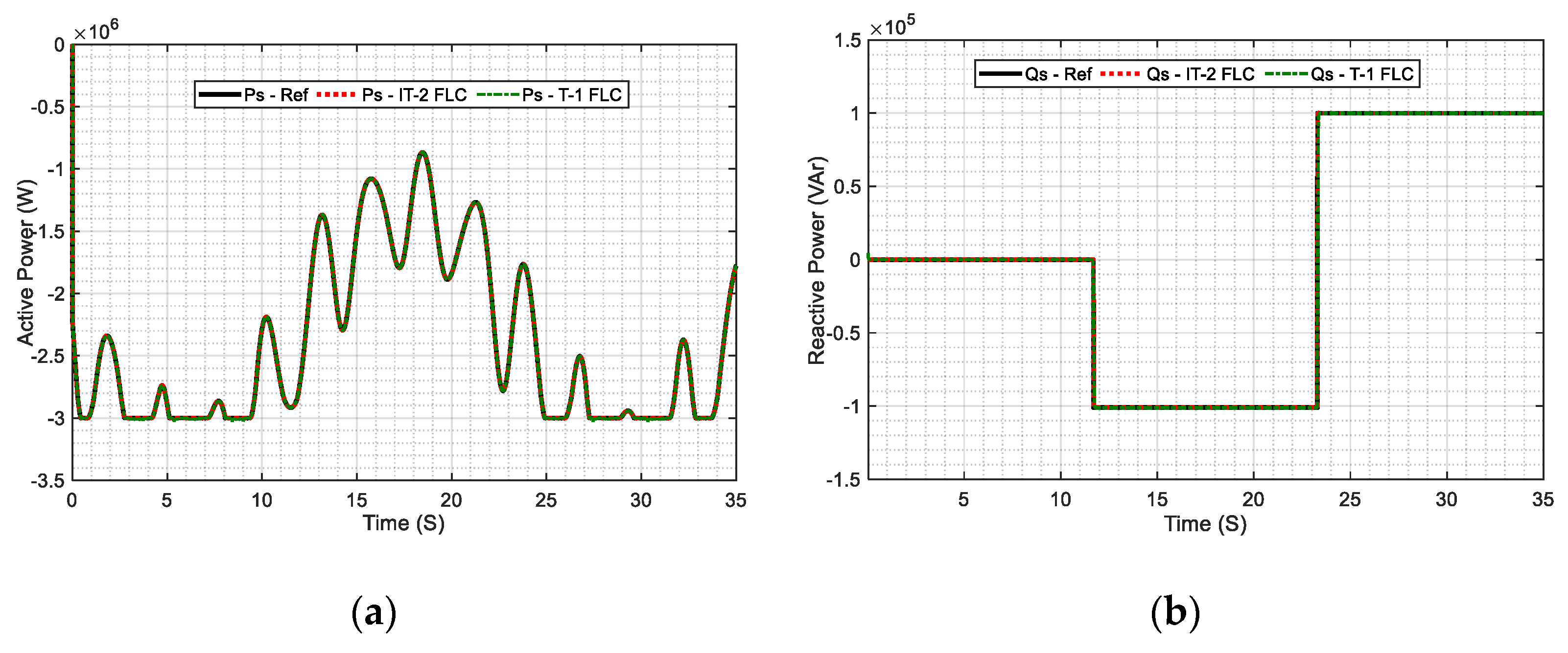
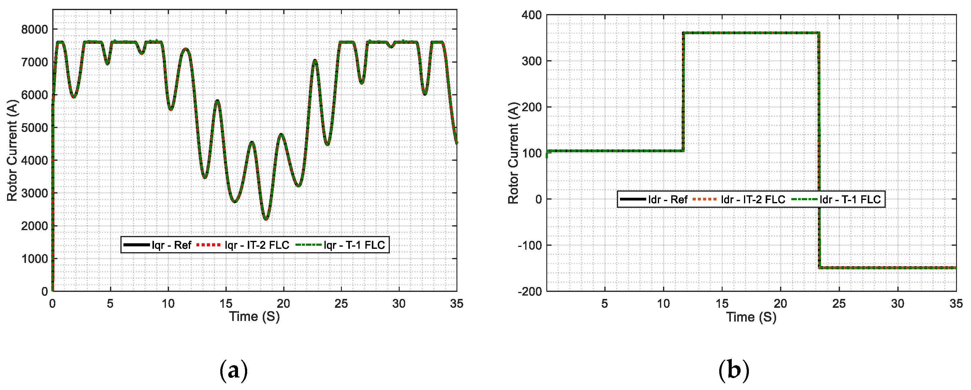
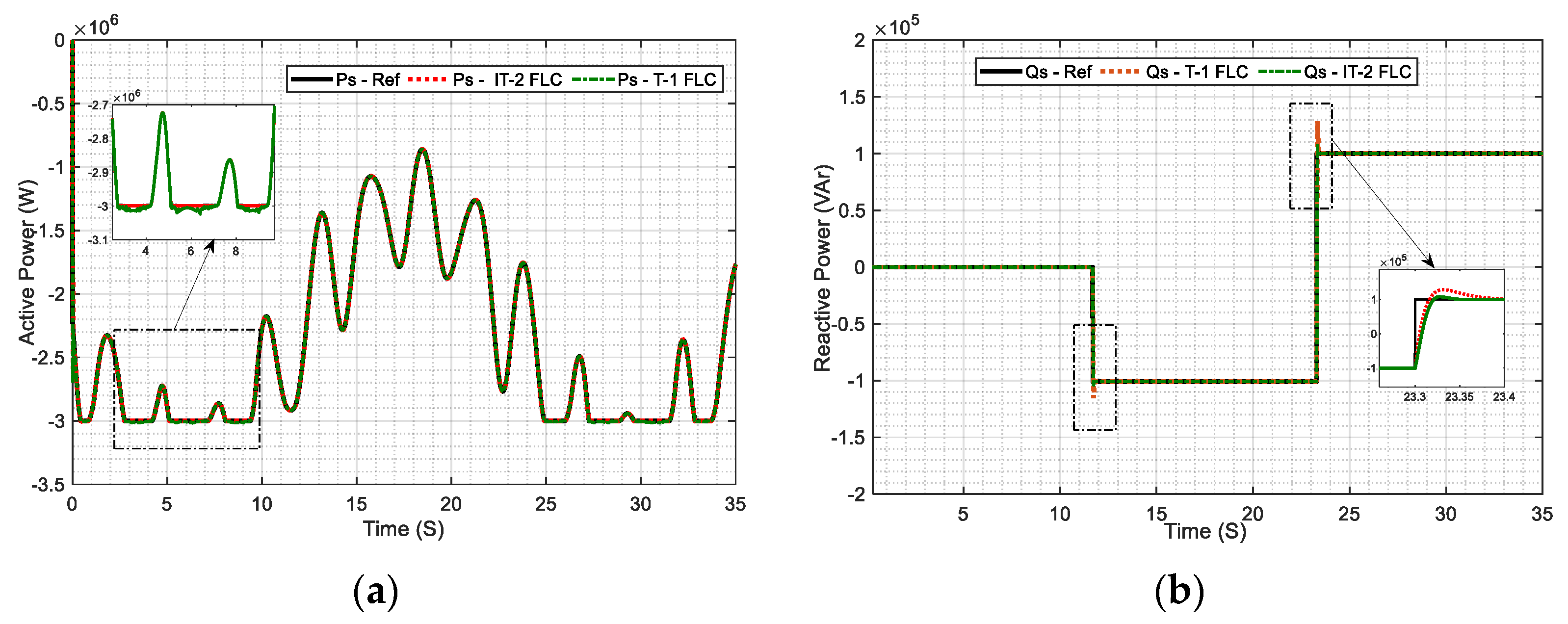
3.1. Reference Tracking

This part investigates the control strategies proposed and tracking performance when the DFIG was working in ideal conditions without perturbations and variations of the parameters.
Figure 8a shows the wind speed profile of the DFIG-based WECS. The wind speed varied around the rated wind speed, which is V n = 12   m / s . The variation of the wind speed provoked the change of functioning in the system, as follows:
-
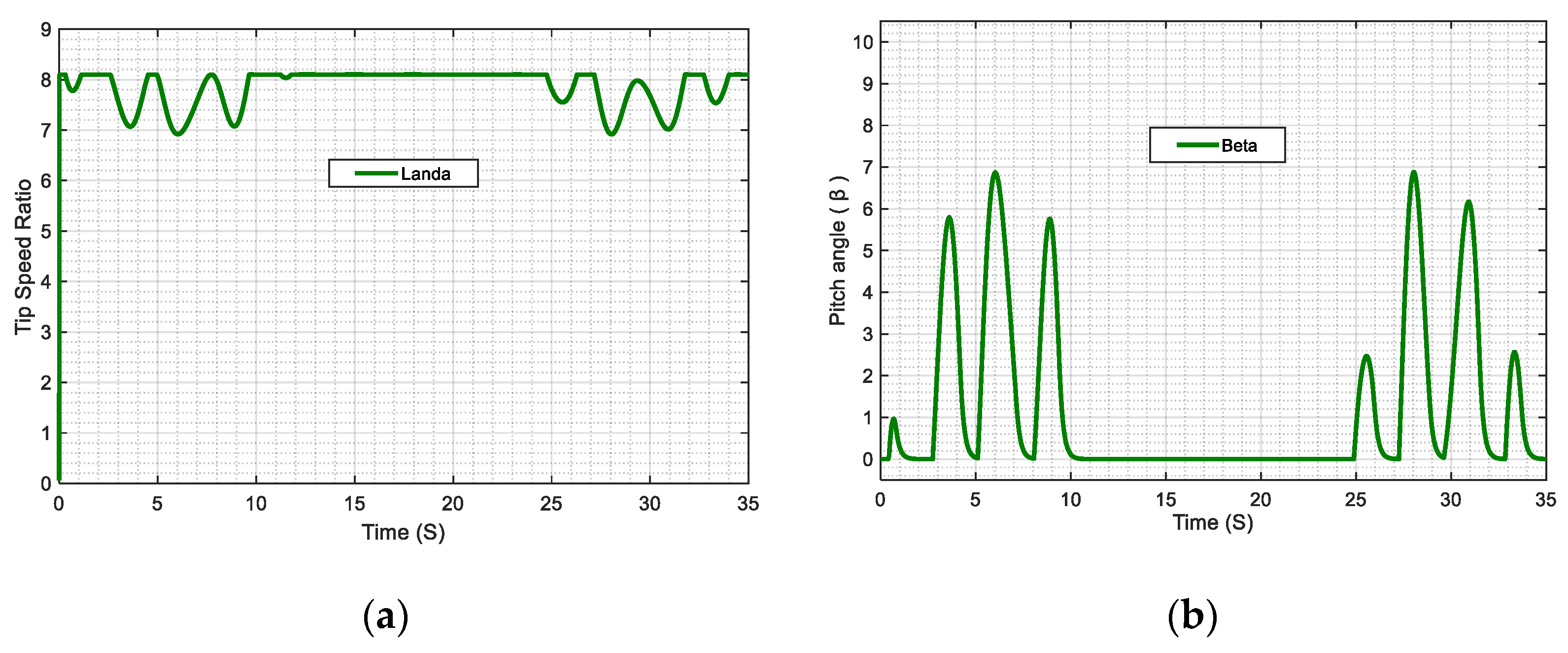
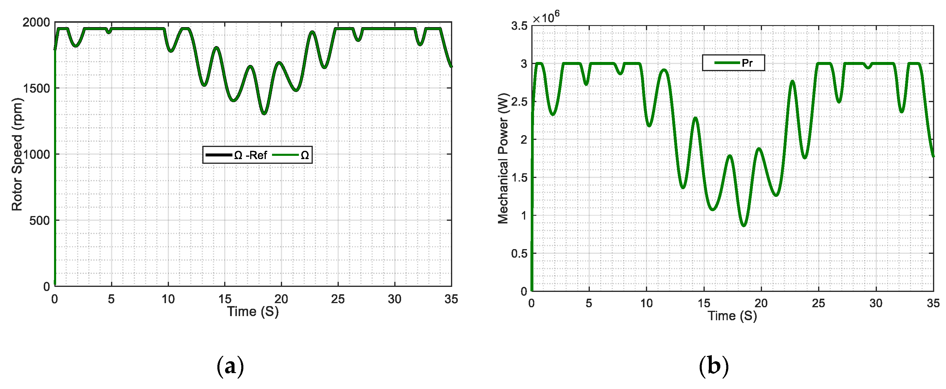
Case 1: The wind turbine operated in the MPPT operating mode when the speed of wind was lower than the rated speed V n = 12   m / s , therefore the wind turbine could generate the maximum power according to the specific wind speed.
-
Case 2: In high wind speeds, the pitch control started operating. Therefore, the pitch angle was increased in order to limit the captured wind energy to its nominal value.
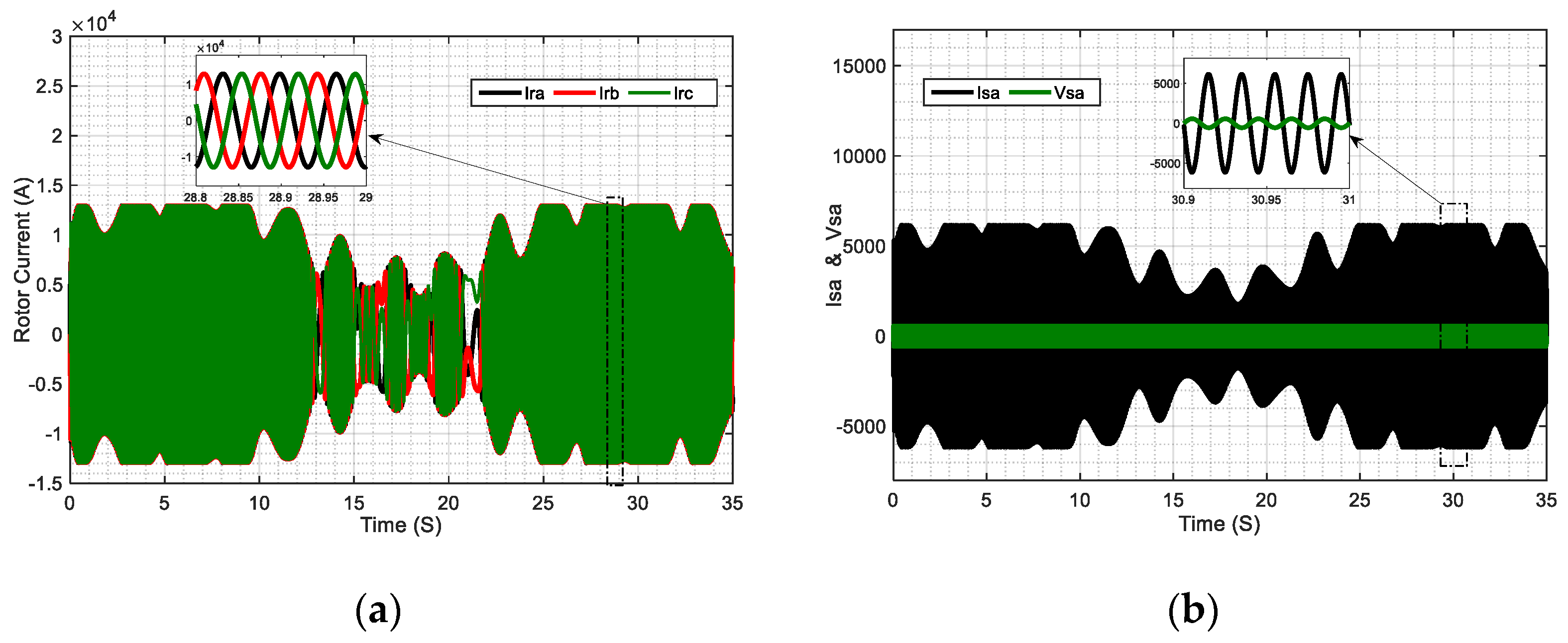
The Figure 8b shows the coefficient of power, which is ( C p ) equal to 0.48 for the MPPT mode and inferior to 0.48 for the pitch control mode.
Figure 9a shows the tip speed ratio λ was maintained at its optimal value λ o p t = 8.1 by the MPPT control and degraded if pitch control mode was activated when the wind speed exceeded the nominal speed. Figure 9b represents the pitch angle controller response for variable wind speed β , which was equal to 0 in MPPT mode, and varied according to the wind speed in pitch control mode to keep the output power at the rated value.
Figure 10a shows the high tracking performance of mechanical speed response ( Ω ) of the proposed controller under a variable turbine speed. It should be noted that the reference speed is given by the MPPT control strategy and the mechanical speed response was stable and tracked the reference value and the shape was similar to the wind variation.
The mechanical turbine power illustrated in Figure 10b changed according to the wind speed variation; also it was maintained in a nominal state when the pitch angle controller was activated.
Figure 11a shows the active power response that tracked the trajectory of wind speed evolution. When the pitch control was activated, the DFIG speed was kept at the nominal values, which implies that the extracted power was maximal. The nominal power ( 3   MW ) was obtained at the rated wind speed V n = 12   m / s and a speed of N m = 1950   rpm . Effectively, as can be seen in this figure, the active power had a negative sign, which means that the DFIG produced and distributed energy to the grid. In Figure 11b, the reactive power response was regulated to zero during the time intervals   0   s ,   11.6   s to get the unity power factor operation. Afterward, it tracked accurately and rapidly the reference power, so it can be noted that the power response was identical to the reference value.
Figure 12a,b illustrates the rotor current responses I q r and I d r under normal conditions (the perturbations and the variations of the parameters of the DFIG do not apply). It can be noted that the rotor currents tracked the reference trajectories without overshooting.
Figure 13a shows that the rotor currents I r a b c , of the DFIG are three-phase and in sinusoidal form. While Figure 13b presents the voltage and current I s a , V s a of a phase of the grid. It can be seen in Figure 13b that the voltage and the current were in phase opposition which means that the active power was injected into the grid and that the power factor was unitary.

3.2. Robustness

This part investigates and tests the proposed controllers’ robustness and the performance under unfavorable variations of the control system parameters and wind speed perturbations.
In the aim to test the robustness of the proposed controller, the parameter values of the DFIG were changed as follows: the rotor resistance R r was increased by 50 % of its nominal value. In addition, the inductors of stator and rotor ( L s , L r ) were varied by 30 % of their nominal values, and L m was decreased by 60 % of the initial value.
Figure 14a,b, shows the result of the comparison between the two controllers, which were the type-1 fuzzy logic controller (T1-FLC), and the proposed interval type-2 fuzzy controller (IT2-FLC). The aim was to test the effectiveness and the robustness of the proposed controller in the case of parametric uncertainties and disturbances. We note that the T1-FLC regulator made small overshooting errors during small intervals of time, then tracked the reference signal, whereas the proposed controller (IT2-FLC) was accurate and did not make any overshooting errors, which proved its robustness against rapid changes of the reference signal, and in the case of disturbances and internal variations in system parameters.
Thus, it can be concluded from simulation results that the proposed controller (IT2-FLC) proved to be a better choice in the case of variations of the parameters and the uncertainties of disturbances of the system.

4. Conclusions

In this paper, we have applied a new control strategy based on an interval type-2 fuzzy logic controller and a doubly fed induction generator (DFIG). First a mathematical model of the DFIG and wind turbine model were presented. Then, two control strategies, pitch control and MPPT mode, were presented; the profile of the wind speed used made it possible to observe the operation of the wind turbine in the two modes according to the value of the wind speed: MPPT mode and pitch control mode.
In order to show the effectiveness of the proposed control strategy, the system was controlled using both the T1-FLC and IT2-FLC. Then, the system was tested in two different cases: in the case of very high wind speed disturbances, and in the case of parameter variations in the system. The results were obtained with both the T1-FLC and IT2-FLC.
Results showed that the interval type-2 fuzzy logic controller had better performance and outperformed the type-1 fuzzy logic controller (T1-FLC), especially in the case of disturbances, also the IT2-FLC had lower overshoot and fast rise time, making its performance more superior to that of the T1-FLC.
Future work will focus on the use of other types of robust controllers. We are currently designing and implementing an intelligent hybrid controller based on interval type-2 fuzzy logic, and a second-order sliding-mode controller proposed to control a variable speed wind turbine based on a doubly fed induction generator (DFIG).

Author Contributions

A.V.H. and A.B. developed the idea and supervised the project and executed the simulation. A.A. and S.M.o.M.E.M. supervised the project. A.V.H. and A.B. helped during the revised version in responding to the editor/reviewers’ comments. A.V.H. and M.M. helped in writing and proofreading the manuscript. All authors have read and agreed to the published version of the manuscript.

Funding

This research received no external funding.

Acknowledgments

Authors are thankful to Mohammadia School of Engineers (EMI), Mohammed V University in Rabat, Morocco where this work was conducted.

Conflicts of Interest

Authors declare no conflicts of interest.

References

  1. ÓhAiseadha, C.; Quinn, G.; Connolly, R.; Connolly, M.; Soon, W. Energy and Climate Policy—An Evaluation of Global Climate Change Expenditure 2011–2018. Energies 2020, 13, 4839. [Google Scholar] [CrossRef]
  2. Flores-Granobles, M.; Saeys, M. Minimizing CO2 emissions with renewable energy: A comparative study of emerging technologies in the steel industry. Energy Environ. Sci. 2020, 13, 1923–1932. [Google Scholar] [CrossRef]
  3. Gargab, F.Z.; Allouhi, A.; Kousksou, T.; El-Houari, H.; Jamil, A.; Benbassou, A. A New Project for a Much More Diverse Moroccan Strategic Version: The Generalization of Solar Water Heater. Inventions 2021, 6, 2. [Google Scholar] [CrossRef]
  4. Moutchou, R.; Abbou, A.; Hemeyine, A.V. Control of the active and reactive powers of a permanent magnet synchronous generator using singular perturbations decouplage. In Proceedings of the 9th International Renewable Energy Congress (IREC), Hammamet, Tunisia, 20–22 March 2018; pp. 1–6. [Google Scholar]
  5. Rhaili, S.; Abbou, A.; Marhraoui, S.; El Hichami, N.; Hemeyine, A.V. Robustness investigation of Vector Control of Five-phase PMSG based Variable-Speed Wind Turbine under faulty condition. In Proceedings of the 2018 Renewable Energies, Power Systems & Green Inclusive Economy (REPS-GIE), Casablanca, Morocco, 23–24 April 2018; pp. 1–6. [Google Scholar]
  6. Khan, D.; Ansari, J.A.; Khan, S.A.; Abrar, U. Power Optimization Control Scheme for Doubly Fed Induction Generator Used in Wind Turbine Generators. Inventions 2020, 5, 40. [Google Scholar] [CrossRef]
  7. Abdelrahem, M.; Hackl, C.M.; Kennel, R. Limited-Position Set Model-Reference Adaptive Observer for Control of DFIGs without Mechanical Sensors. Machines 2020, 8, 72. [Google Scholar] [CrossRef]
  8. Kaloi, G.S.; Baloch, M.H.; Kumar, M.; Soomro, D.M.; Chauhdary, S.T.; Memon, A.A.; Ishak, D. An LVRT Scheme for Grid Connected DFIG Based WECS Using State Feedback Linearization Control Technique. Electronics 2019, 8, 777. [Google Scholar] [CrossRef] [Green Version]
  9. Hemeyine, A.V.; Abbou, A.; Tidjani, N.; Mokhlis, M.; Bakouri, A. Robust takagi sugeno fuzzy models control for a variable speed wind turbine based a DFI-generator. Int. J. Intell. Eng. Syst. 2020, 13, 90–100. [Google Scholar] [CrossRef]
  10. Xiong, L.; Li, P.; Li, H.; Wang, J. Sliding Mode Control of DFIG Wind Turbines with a Fast Exponential Reaching Law. Energies 2017, 10, 1788. [Google Scholar] [CrossRef] [Green Version]
  11. Hemeyine, A.V.; Abbou, A.; Bakouri, A.; Labbadi, M.; El Moustapha, S.M.o.M. Power Control for Wind Turbine Driving a Doubly Fed Induction Generator using Type-2 Fuzzy Logic Controller. In Proceedings of the 7th International Renewable and Sustainable Energy Conference (IRSEC), Agadir, Morocco, 27–30 November 2019; pp. 1–6. [Google Scholar]
  12. Rocha-Osorio, C.; Solís-Chaves, J.; Casella, I.R.; Capovilla, C.; Puma, J.A.; Filho, A.S. GPRS/EGPRS standards applied to DTC of a DFIG using fuzzy—PI controllers. Int. J. Electr. Power Energy Syst. 2017, 93, 365–373. [Google Scholar] [CrossRef]
  13. Sami, I.; Ullah, S.; Ali, Z.; Ullah, N.; Ro, J.-S. A Super Twisting Fractional Order Terminal Sliding Mode Control for DFIG-Based Wind Energy Conversion System. Energies 2020, 13, 2158. [Google Scholar] [CrossRef]
  14. Prajapat, G.P.; Bhui, P.; Kumar, P.; Varma, S. Estimation based Maximum Power Point Control of DFIG based Wind Turbine Systems. In Proceedings of the IEEE PES GTD Grand International Conference and Exposition Asia (GTD Asia), Bangkok, Thailand, 19–23 March 2019; pp. 673–678. [Google Scholar]
  15. Bakouri, A.; Mahmoudi, H.; Abbou, A. Intelligent control for doubly fed induction generator connected to the electrical network. Int. J. Power Electron. Drive Syst. 2016, 7, 688–700. [Google Scholar] [CrossRef]
  16. Hemeyine, A.V.; Abbou, A.; Tidjani, N.; Mokhlis, M.; Bakouri, A. Takagi Sugeno Fuzzy Models for Wind Turbine Driving a DFI-Generator via Linear Matrix Inequalities. In Proceedings of the 5th International Conference on Renewable Energies for Developing Countries (REDEC), Marrakech, Morocco, 24–26 March 2020; pp. 1–6. [Google Scholar]
  17. Naik, K.A.; Gupta, C.P. Performance comparison of type-1 and type-2 fuzzy logic systems. In Proceedings of the 4th International Conference on Signal Processing, Computing and Control (ISPCC), Solan, India, 21–23 September 2017; pp. 72–76. [Google Scholar]
  18. Pramanik, T.; Samanta, S.; Sarkar, B.; Pal, M. Fuzzy f-tolerance competition graphs. Soft Comput. 2017, 21, 3723–3734. [Google Scholar] [CrossRef]
  19. Lathamaheswari, M.; Nagarajan, D.; Kavikumar, J.; Phang, C. A review on type-2 fuzzy controller on control system. J. Adv. Res. in Dyn. Control Syst. 2018, 10, 430–435. [Google Scholar]
  20. Bai, Y.; Wang, D. On the Comparison of type-1 and Interval type 2 Fuzzy Logic Controllers Used in a Laser Tracking System. IFAC-PapersOnLine 2018, 51, 1548–1553. [Google Scholar] [CrossRef]
  21. Naik, K.A.; Gupta, C.P.; Fernandez, E. Design and implementation of interval type-2 fuzzy logic-PI based adaptive controller for DFIG based wind energy system. Int. J. Electr. Power Energy Syst. 2020, 115, 105468. [Google Scholar] [CrossRef]
  22. Yassin, H.; Hanafy, H.; Mohab, M. Enhancement Low-voltage Ride Through Capability of Permanent Magnet Synchronous Generator-based Wind Turbines Using Interval Type-2 Fuzzy Control. IET Renew. Power Gener. 2016, 10, 339–348. [Google Scholar] [CrossRef]
  23. Kumbasar, T. A simple design method for interval type-2 fuzzy PID controllers. Soft Comput. 2014, 18, 1293–1304. [Google Scholar] [CrossRef]
  24. LathaMaheswari, M.; Nagarajan, D.; Kavikumar, J.; Broumi, S. Triangular interval type-2 fuzzy soft set and its application. Complex Intell. Syst. 2020, 6, 531–544. [Google Scholar] [CrossRef]
  25. Raju, S.K.; Pillai, G.N. Design and Implementation of Type-2 Fuzzy Logic Controller for DFIG-Based Wind Energy Systems in Distribution Networks. IEEE Trans. Sustain. Energy 2015, 7, 345–353. [Google Scholar] [CrossRef]
  26. Hamza, M.F.; Yap, H.J.; Choudhury, I.A. Recent advances on the use of meta-heuristic optimization algorithms to optimize the type-2 fuzzy logic systems in intelligent control. Neural. Comput. Appl. 2017, 28, 979–999. [Google Scholar] [CrossRef]
  27. Taskin, A.; Kumbasar, T. An Open Source Matlab/Simulink Toolbox for Interval type-2 Fuzzy Logic Systems. In Proceedings of the IEEE Symposium Series on Computational Intelligence, Cape Town, South Africa, 7–10 December 2015; Volume 1, pp. 1561–1566. [Google Scholar]
Figure 1. (a) Wind energy conversion system (WECS) based on a direct drive dual field induction generator (DFIG); (b) curves of the power coefficient ( C p ) as a function of λ and β .
Inventions 06 00021 g001
Figure 2. The schematic of the control of the DFIG-based WECS using the IT2-FLC.
Inventions 06 00021 g002
Figure 3. Type-2 fuzzy logic sets with footprint of uncertainty (FOU) and embedded fuzzy set (FS).
Inventions 06 00021 g003
Figure 4. Structures of fuzzy logic control: (a) type-1 fuzzy logic controller (T1-FLC); (b) interval type-2 fuzzy logic controller (IT2-FLC).
Inventions 06 00021 g004
Figure 5. Type-1 fuzzy membership functions (MFs): (a) MFs for input variable ‘e’ and ‘de’ of the T1-FLC; (b) MFs for output variable ‘u’ of the T1-FLC.
Inventions 06 00021 g005
Figure 6. Type-2 fuzzy membership functions (MFs): (a) MFs for input variable ‘e’ and ‘de’ of the IT2-FLC; (b) MFs for output variable ‘u’ of the IT2-FLC.
Inventions 06 00021 g006
Figure 7. Schematic model of the interval type-2 fuzzy controller (IT2-FLC).
Inventions 06 00021 g007
Figure 8. (a) Wind speed ( V w ) profile; (b) power coefficient ( C p ).
Inventions 06 00021 g008
Figure 9. (a) Tip speed ratio ( λ ); (b) pitch angle variations (β).
Inventions 06 00021 g009
Figure 10. (a) Rotor speed ( ); (b) mechanical power ( P r ) of the DFIG.
Inventions 06 00021 g010
Figure 11. (a) Active power ( P s ) comparison under normal conditions; (b) reactive power ( Q s ) comparison under normal conditions.
Inventions 06 00021 g011
Figure 12. Rotor current response comparison under normal conditions; (a) rotor current ( I q r ); (b) rotor current ( I d r ).
Inventions 06 00021 g012
Figure 13. (a) Rotor currents I r a , I r b , and I r c ; (b) Stator currents I s a and stator voltage V s a .
Inventions 06 00021 g013
Figure 14. (a) Active power tracking comparison under parameters variation; (b) reactive power tracking comparison under parameters variation.
Inventions 06 00021 g014
Table 1. Fuzzy logic control rule base tables.
Error E r r o r
NBNMNSEZPSPMPB
NBNBNBNBNBNMNSEZ
NMNBNBNBNMNSEZPS
NSNBNBNMNSEZPSPM
EZNBNMNSEZPSPMPB
PSNMNSEZPSPMPBPB
PMNSEZPSPMPBPBPB
PBEZPSPMPBPBPBPB
Table 2. Wind turbine parameters.
ParametersValues
Radius of the blades 45   m
Gear ratio 100
Total Inertia 254   Kg . m 2
Friction coefficient 0.24
Table 3. Doubly fed induction generator parameters.
ParametersValues
Rated power 3 MW
Frequency 50 Hz
Stator voltage 690 V
Stator inductance 12.241   mH
Stator resistance 2.97   m
Rotor resistance 3.82   m
Rotor inductance 12.177   mH
Mutual inductance 12.12   mH
Number of pole pairs 2
Publisher’s Note: MDPI stays neutral with regard to jurisdictional claims in published maps and institutional affiliations.

