1. Introduction
Advanced initiatives in the synergistic fields of particle physics and photon production dictate an increasing need for high-energy linear accelerators (linacs). This need has motivated the investigation of novel techniques to obtain the highest achievable accelerating gradients. During the last decades, several conceptual linear collider facilities relying on diverse concepts have indeed been investigated, with proposed solutions that range from C-band (∼6 GHz) and X-band (∼12 GHz) radio-frequency (RF) linacs to superconductivity and plasma acceleration [
1,
2,
3,
4]. Each technique presents advantages in different aspects, such as the maximum field strength, power consumption, beam quality, and maturity of the technology. Among the latter, plasma wakefield acceleration schemes [
5,
6] certainly constitute an attractive technique to achieve strong accelerating gradients that are up to three orders of magnitude higher compared to conventional RF structures. In particular, particle-driven plasma wakefield acceleration (PWFA) is a configuration obtained by using the intense wakefields excited in the plasma by a high-charge
driver beam in order to accelerate a low-charge
witness beam that is properly delayed. Moreover, driver beams also exist in the form of multi-pulse, optionally charge-modulated, trains that can resonantly enhance the excitation of the plasma, resulting in stronger accelerating fields. The aforementioned PWFA configurations are known as
laser comb beams since they are obtained by shaping the longitudinal structure of the UV photons impinging on the photocathode [
7,
8,
9]. Comb beams are typically pre-accelerated in an injector stage, usually made by RF accelerating structures, before the injection into one or more plasma stages occurs. The dynamics characterizing the RF injector are very rich and somewhat challenging. Indeed, in addition to boosting the beam energy, the injector stage also allows one to manipulate the time-structure of the comb beam, whose impact is crucial in PWFA schemes. Moreover, the low-energy regime (typically below a few hundreds of MeV) that is characteristic of the injector stage makes the beam more sensitive to imperfections of the machine and the excitation of parasitic wakefield effects induced in the RF linacs [
10]. Thus, this paper focuses on the dynamics of comb beams in the RF injector stages preceding the plasma, with particular emphasis on the longitudinal phase space manipulation and the emittance dilution induced by parasitic short-range wakefields (SRWF) excited in the surrounding linac structures. Both aspects are in fact crucial for an efficient acceleration process in the plasma since the former allows one to control the individual length of the pulses as well as their separation, whereas the latter is responsible for either parasitic intra-pulse coupling or mutual coupling among different pulses. The analyses presented in this paper are performed with the tracking code MILES [
11], a tool developed by us utilizing semi-analytical models for a fast evaluation of space charge forces and wakefield effects. Given the computational advantages of the simplified models over conventional methods, such as particle-in-cell (PIC) for space charge and convolution integrals for wakefields, we extended this tool to describe the dynamics of beams in the comb configuration. It has to be stressed that, as the beam–plasma interaction is a complex process, to find simplified models capable of describing such a problem is beyond our scopes, and dedicated PIC codes should be used for this task (e.g., [
12,
13]). However, we believe that the study of comb beam manipulation, as well as the evaluation of SRWF effects in the injector, is still a subject of interest.
This paper is organized as follows.
Section 2 describes the longitudinal manipulation of a driver plus witness beam achieved in the “velocity bunching” configuration.
Section 3 demonstrates the possibility of tracking multi-pulse driver beams with MILES, and finally,
Section 4 summarizes our investigation of SRWF effects in a comb beam accelerated in the RF linac prior to a plasma stage. Moreover, the examples discussed within this paper are primarily based on two different facilities: the SPARC linac [
14] (
Section 2 and
Section 3), in operation at Frascati National Laboratories, and EuPRAXIA@SPARC_LAB [
15] (
Section 4), under development in the same site.
2. Velocity Bunching and Longitudinal Manipulation of a Comb Beam
Time-harmonic accelerating structures crucially affect the longitudinal dynamics of charged particles. Indeed, the time-dependent acceleration that particles experience in RF fields introduces a time–energy correlation that leads, eventually, to phase slippage effects. This mechanism can be utilized to introduce advantageous manipulations of the longitudinal phase space. In this section, we discuss the longitudinal compression of a comb beam obtained in the so-called velocity bunching configuration.
The longitudinal dynamics of charged particles in RF accelerating structures can be described by the phase-energy equation set [
16]. It is customary to define the dynamical variables
where the RF angular frequency
and wavenumber
,
c being the speed of light in vacuum, normalize the longitudinal position
z occupied at time
t, while
T is the kinetic energy. The evolution of the phase and energy variables in a traveling wave (TW) accelerating structure is described by the coupled first-order differential equations
where the parameter
accounts for the amplitude of the RF field potential, with
being the average accelerating field and the prime symbol representing differentiation with respect to
z. From the top equation in (
2), it can be deduced that significant phase variations are only expected at low energy, since for
, one has
. Nevertheless, a positive phase slippage occurs at low
values and the phase approaches the upper bound
as
. This process is utilized in rectilinear compressors where acceleration and longitudinal beam focusing are provided simultaneously by injecting the beam off-crest [
17]. Indeed, injecting the beam centroid close to
introduces a large time–energy correlation that allows for a strong compression while the beam slips to accelerating phases, increasing its energy. This configuration, known as
velocity bunching, is often employed in linac boosters following RF guns to enhance the peak current up to one order of magnitude and is also compatible with the emittance compensation scheme [
18,
19]. In the comb beam configuration, the velocity bunching can be utilized to manipulate both the individual length of the driver and witness beams as well as their separation [
20], which are both crucial in PWFA schemes.
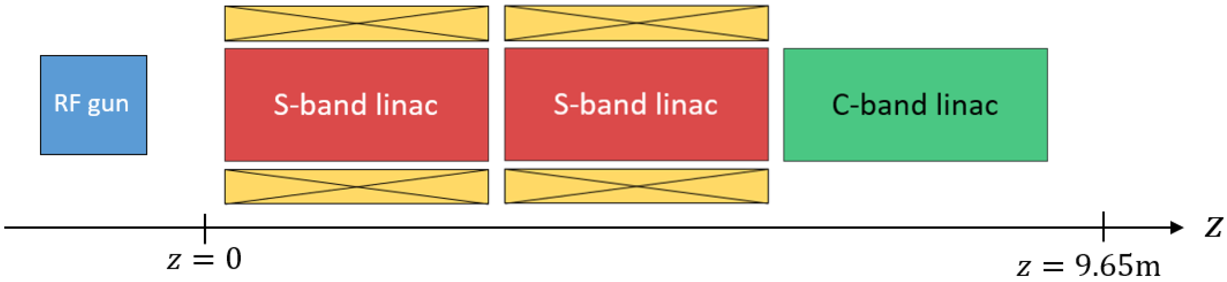
In the remaining part of this section, we use MILES to investigate the injection of a typical comb beam from the SPARC [
14] RF gun into a TW linac. The overall injector stage for SPARC, shown in
Figure 1, is approximately 12 m long, and it comprises an S-band (2.856 GHz) RF gun, two S-band TW linacs surrounded by focusing solenoid magnets, and a C-band (5.712 GHz) TW linac.
The charge configuration in the current working point foresees a
driver and a
witness beam. For fine control of the individual bunch lengths as well as the final separation, the beam is launched with the witness in front, and the velocity bunching technique is employed in the first S-band accelerating section to move it behind the driver and obtain, at the same time, the desired compression. The beam energy at the injection into the booster linac is ∼
, and the witness-driver separation is ∼4 ps. In
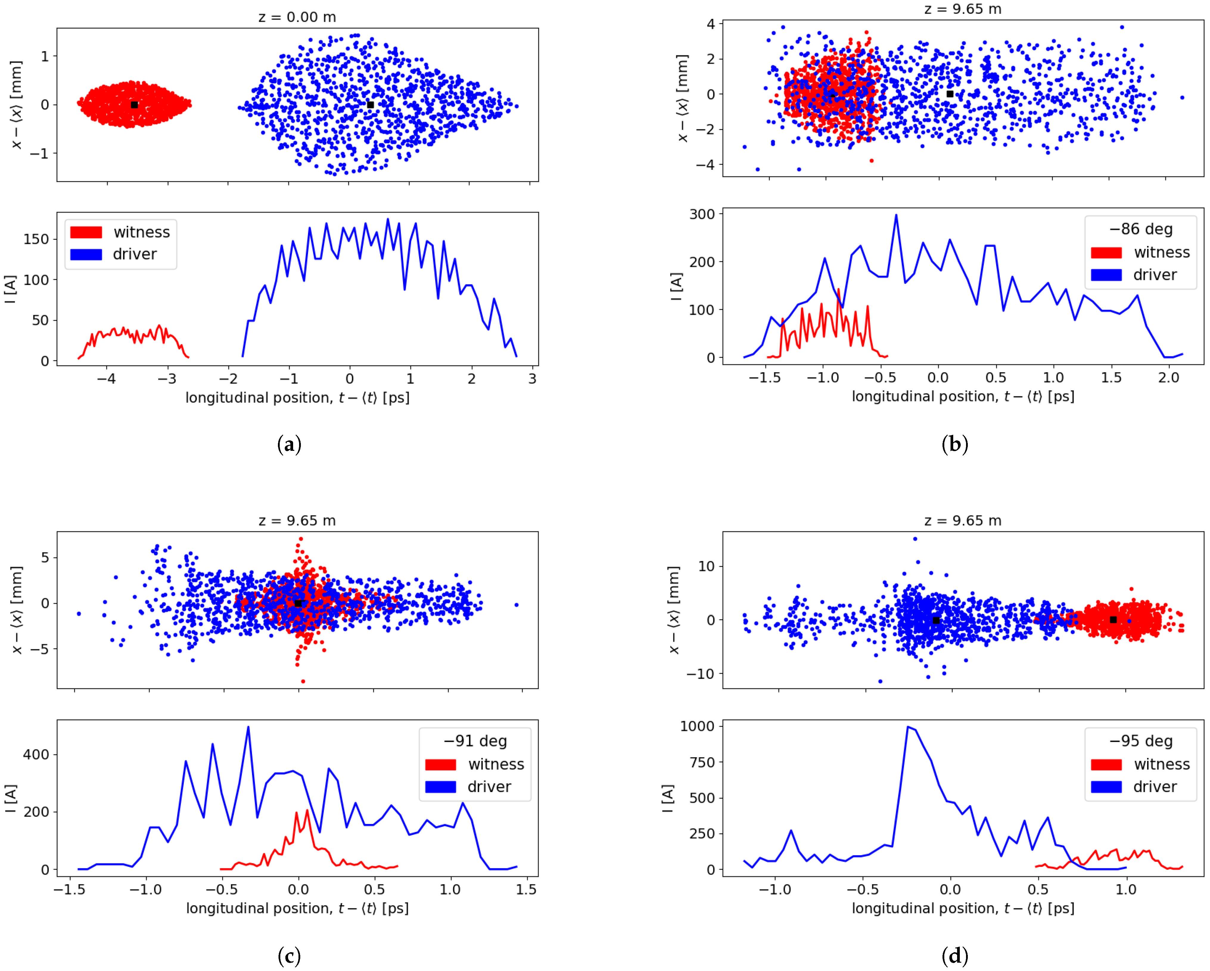
Figure 2, we show the effect of the injection phase in the first section on the longitudinal compression of the comb beam. In particular, Equation (
2) is introduced in MILES to take into account the phase slippage of the beam center with respect to the RF crest in addition to the usual energy variations. The initial spatiotemporal configuration before the beam enters the linac booster, arbitrarily chosen as z = 0, is shown in
Figure 2a; the witness, in red, is ∼4 ps ahead of the driver, in blue. The two centroids (black squares) and the slice current profiles (bottom) are also represented. We should also point out that in the spatiotemporal plots, the macro-charge assigned to the macro-particles in the driver and in the witness differs by a factor ten. In
Figure 2b–d, the beam is shown at the exit of the injector stage, approximately 12 m from the cathode and at an energy of ∼95 MeV, for different values of the injection phase in the first S-band section. The figure shows that the operation at injection phases close to the zero-crossing introduces a significant time–velocity correlation such that, as the bunching effect becomes stronger, the two beams gradually swap their position and the driver propagates in front. We note that, as the beam distribution is compressed, the longitudinal space charge (LSC) force intensifies, acting against the TW fields whose action must, in general, be strong in order to perform the manipulation successfully. In addition, such a force exhibits a gradient across the beam (see, e.g., [
21]) that affects the net energy chirp introduced by the off-crest TW field. As a consequence, we observe that the maximum compression occurs a few degrees away from the zero-crossing.
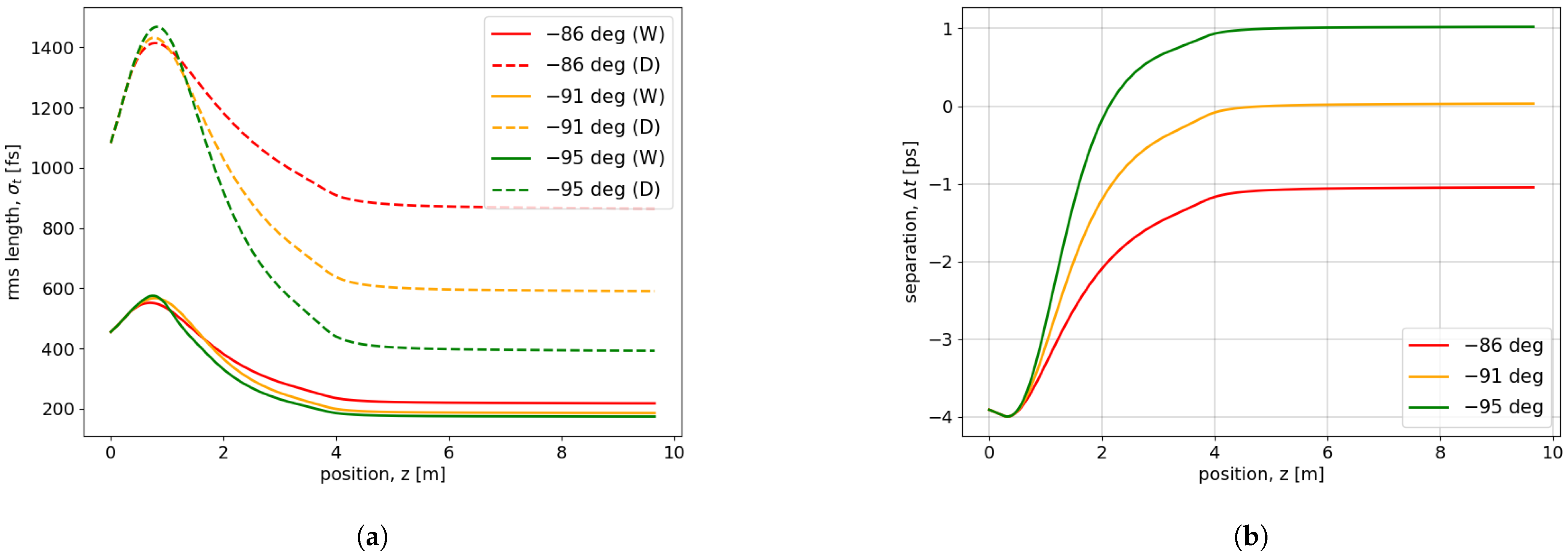
Additional aspects of the velocity bunching process in the injector stage are also reported in
Figure 3, where the individual compression of the pulses as well as their separation are shown along the linac. In particular,
Figure 3a shows that both the driver and witness beams become shorter, thus increasing their brightness, for the −95 degree injection phase. Similarly, the distance between the two centroids is shown in
Figure 3b, where positive distances correspond to the driver being in front. It can be observed that the −95 degree case provides a final separation of ∼1 ps (i.e., 300
m), which is close to the characteristic plasma wavelength of the plasma capillary installed downstream of the injector stage at the SPARC lab, thus representing a good working point.
3. Tracking of Multi-Pulse Driver Beams
The purpose of this section is to demonstrate the possibility of tracking multi-driver pulse trains in MILES, a natural extension of the single driver plus witness configuration. The use of multi-pulse driver beams with proper spacing and, optionally, a charge modulation resonantly excites the plasma, enhancing the strength of the resulting accelerating wakefield experienced by the witness beam. Therefore, there is a large interest in exploiting the benefits associated with this scheme [
22,
23]. In our example, we will consider the configuration described in
Section 4 of ref. [
22] concerning the measured longitudinal phase space of a four driver plus witness comb beam from the SPARC injector stage. The individual beam parameters measured at the exit of such a stage are summarized in
Table 1, and the relative distances among consecutive pulses are as follows: 270
m (D1-D2), 240
m (D2-D3), 420
m (D3-D4), 495
m (D4-W).
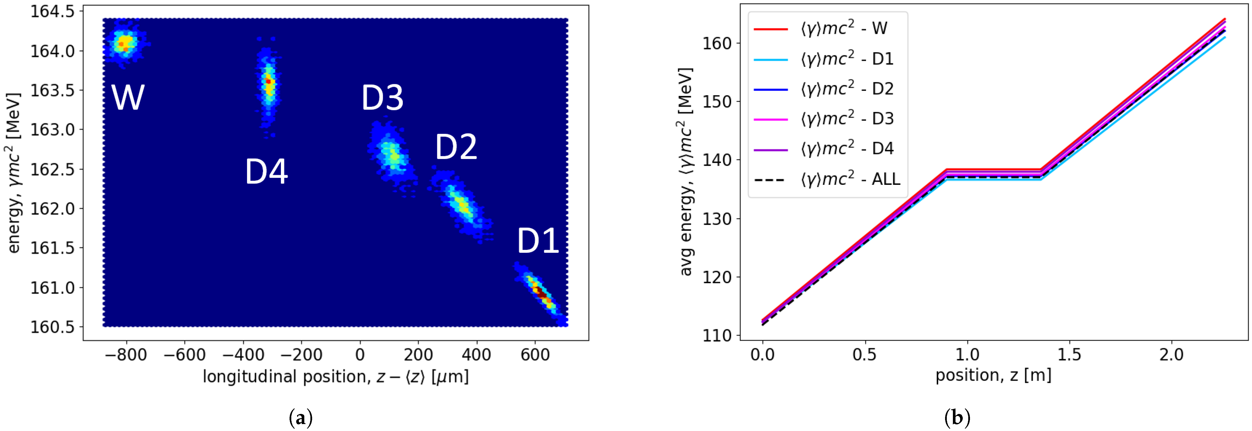
For the purpose of our demonstration, we perform a simple tracking exercise considering an X-band (∼12 GHz) TW linac made of two 0.9 m long sections operated at
accelerating gradient.
Figure 4 shows the longitudinal phase space after the aforementioned linac stage as well as the evolution of the mean energy for each pulse in the multi-driver comb beam (the brackets
in the axis label imply an average over each pulse subset). The time structure of such a beam does not change with the acceleration and shows the irregular pulse-to-pulse spacing discussed by the authors in [
22]. As commented by them, the irregular spacing can, in principle, be adjusted in the future by inserting delay lines for each laser pulse illuminating the photo-cathode instead of using a fixed separation. However, the hybrid spacing utilized in the current working point at SPARC also shows some advantages. Indeed, if a plasma wavelength of
m (
cm
−3 density) is assumed, such a configuration has the first three bunches at a similar separation of ∼
and the last two at ∼
. The wakefield produced by this hybrid spacing was found to show a good compromise between the amplitude of the accelerating field and the net driver-to-witness energy transfer.
4. Short-Range Wakefield Effects in Comb Beams
Charged beams propagating in RF accelerating structures excite self-induced electromagnetic fields that, once diffracted by the discontinuities in the surrounding geometry, perturb the motion of the beam itself. This parasitic interaction over the typical beam time-scale is known as
short-range wakefield (SRWF) and introduces mutual coupling, which is responsible for effects such as undesired energy exchange and transverse deflection [
10]. In particular, the former leads to intra-beam energy spread, whereas the slice-dependent deflection leads to larger projected RMS emittance, thus reducing the beam brightness. In the case of comb beam configuration, it is important to evaluate the impact of SRWFs, which cause intra-pulse coupling as well as driver-to-witness coupling, which constitute a potential source of quality loss. Such effects are notoriously present in periodic RF accelerating structures, where the wakefields are mainly induced by the field scattered by the cell irises. This process is described by use of diffraction theory [
24,
25,
26] and well-known asymptotic formulas for the monopole, and dipole wake functions per unit length of short bunches can be found in [
27]. The latter express the momentum change induced by a source particle on a test particle traveling a distance
behind and are given by
where
,
, with
a being the iris radius,
g the gap size, and
p the period length of the unit cell.
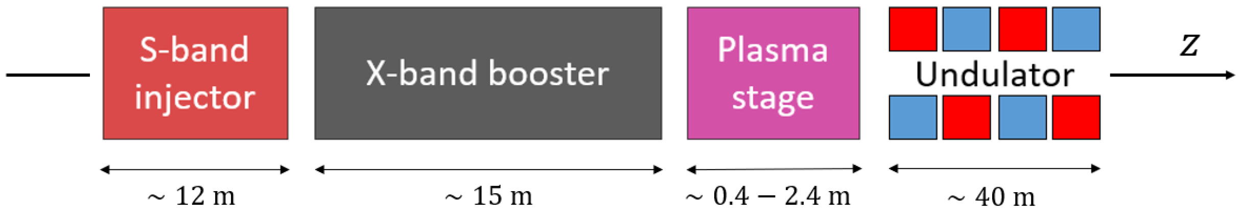
In this section, we aim to investigate the effects of short-range wakefields excited in the RF linac preceding a plasma stage on a comb beam. The example we discuss refers to the X-band linac booster of EuPRAXIA@SPARC_LAB (European Plasma Research Accelerator with eXcellence In Applications), a plasma-based X-ray FEL user facility under development at Frascati National Laboratories (INFN-LNF) [
15]. This facility pre-accelerates comb (driver plus witness) beams in an RF linac stage made by an S-band (2.856 GHz) injector followed by a X-band (11.9942 GHz) booster where the electrons achieve up to ∼
and ∼
energies, respectively. Subsequently, a PWFA plasma stage increases the energy of the witness beam up to ∼
, after which an undulator system induces the lasing process, as illustrated in
Figure 5.
As suggested by Equation (3), wakefield effects in RF linacs are especially relevant for small cell irises, which are characteristic of high-frequency structures such as those in the X-band stage. In particular, transverse dipole wakes represent a main issue since they are responsible for beam breakup (BBU) effects [
28], leading to instabilities and degradation of the projected emittance [
29]. Therefore, in this section, we use the code MILES to investigate the emittance growth in the presence of alignment errors in the X-band linac stage of the EuPRAXIA@SPARC_LAB facility.
Table 2 summarizes the main parameters characterizing the driver and the witness beams at the output of the S-band injector, which precedes the X-band linac, as shown in the layout of
Figure 5.
A single stage of X-band linac at EuPRAXIA@SPARC_LAB consists of eight traveling wave accelerating sections operating in the
phase advance mode. The length of a single section is approximately 0.9 m, and the accelerating gradient is ∼
. The transverse focusing is provided by a set of alternating gradient quadrupoles with strength
located in the drift spaces among consecutive linac sections. In
Figure 6, we assume that the eight TW structures constituting a single X-band linac stage are affected by offset errors with alternate sign. In the plots, the linac stage starts at
after a matching section made of quadrupole magnets separated by drift regions, and the errors are
m (left) and
m (right). It can be noticed that, as the beam travels off-axis in the linac exciting dipole wakefields, the emittance of the driver grows and so does the emittance of the overall distribution. However, for both cases, the witness is only slightly affected by this process since, due to its short dimensions, the intra-beam correlation remains moderate. Nevertheless, the efficient operation of a PWFA stage requires one to properly match the beam to the plasma channel. Thus, the change in the spotsize and divergence resulting from the magnification of the driver emittance can lead to a slight mismatch and compromise the acceleration process in the plasma. As the transverse spot size is given by
, where
is the betatron function and
is the RMS geometric emittance, the resulting spot size scales as the square root of the emittance variation. In the case of 50
m misalignments, the spot size magnifies by a factor of ∼1.3, which does not represent a concern. The matching can, in fact, be easily restored by acting on the optics to modify the betatron function and adjust the beam envelope. Instead, for the 150
m case, the final emittance of the driver is four times the original value, which duplicates the nominal spot size. Based on the machine design report [
15] and dedicated discussions with its authors, this level of mismatch was found to be unacceptable, thus setting the tolerances for the section-to-section alignment in the X-band stage. However we should also note that, more generally, it is possible to mitigate the emittance dilution by use of correction techniques for the trajectory aimed at suppressing the excitation of dipole wakefields. Such schemes exploit beam-based alignment (BBA) concepts [
30,
31], where correction kicks are provided by a set of steering magnets to adjust the beam trajectory, which allows one to keep the emittance degradation under control.
5. Conclusions
The investigation of novel high-gradient techniques represents a priority in the accelerator community as such concepts can strongly improve the performance of current and future facilities, extending the panorama of their applications. In particular, plasma wakefield acceleration constitutes a breakthrough toward higher accelerating fields and thus provides an attractive alternative to RF linacs. However, the dynamics of charged particles in the intense plasma wakefields are extremely challenging, and preserving the high beam quality demanded by the applications becomes arduous. Such a problem requires careful study, which affects, in addition, the design of the injector stage preceding the plasma. In this paper, we have discussed some peculiar aspects characterizing the beam dynamics in such RF injector stages’ pre-accelerating particle distributions in the comb configuration. The first part of the paper is focused on the longitudinal phase space manipulation, aimed at obtaining comb beams with the desired time-structure. We have investigated different injection scenarios obtained with the velocity bunching technique, which provides longitudinal compression and acceleration simultaneously. As a result, we observed the individual bunching of the driver and the witness beam while adjusting at the same time their separation. Moreover, we have also presented an additional example with a multi-pulse driver beam, discussing the impact of the irregular time-structure on PWFA schemes. The second part of the paper is dedicated to studying emittance dilution effects on comb beams that are induced by the excitation of dipole SRWFs in multi-cell RF linacs. Preserving the beam brightness is notoriously crucial, and the time-dependent deflection generally degrades the projected emittance, leading to considerable mismatches. We have shown two cases of alignment errors to discuss the tolerances for an X-band linac stage and discussed possible mitigation techniques for smaller errors.


 ,
, 


