
Advances in P(VDF-TrFE) Composites: A Methodical Review on Enhanced Properties and Emerging Electronics Applications

 ,
,
Abstract
:1. Introduction
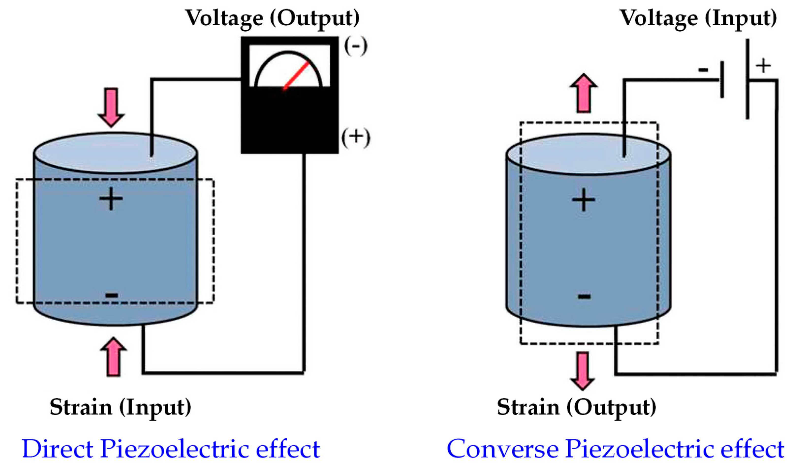
1.1. Piezoelectric Effect
- S: the strain, relative deformation
- : compliance, inverse of elasticity, under constant electric field
- T: applied stress
- d: piezoelectric charge constant
- E: applied electric field
- D: dielectric displacement
- : dielectric constant under constant stress
1.2. Piezoelectric and Ferroelectric Polymer
1.3. General Mechanism to Enhance the Properties of Polymer
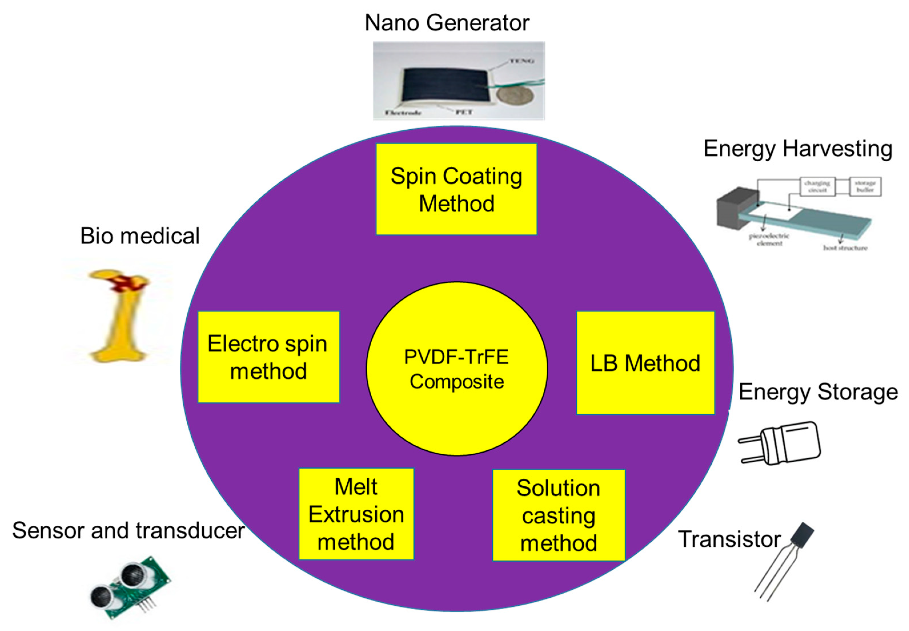
2. Synthesis Methods of P(VDF-TrFE) Composite and Their Applications
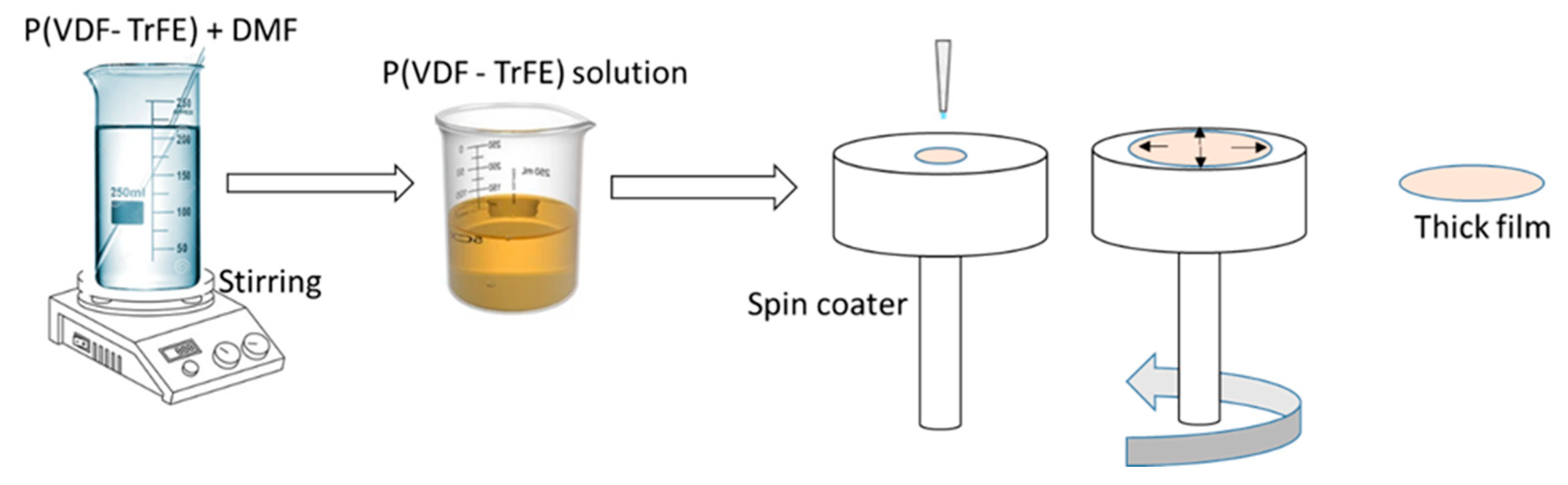
2.1. Composite Prepared from Spin-Coating Method
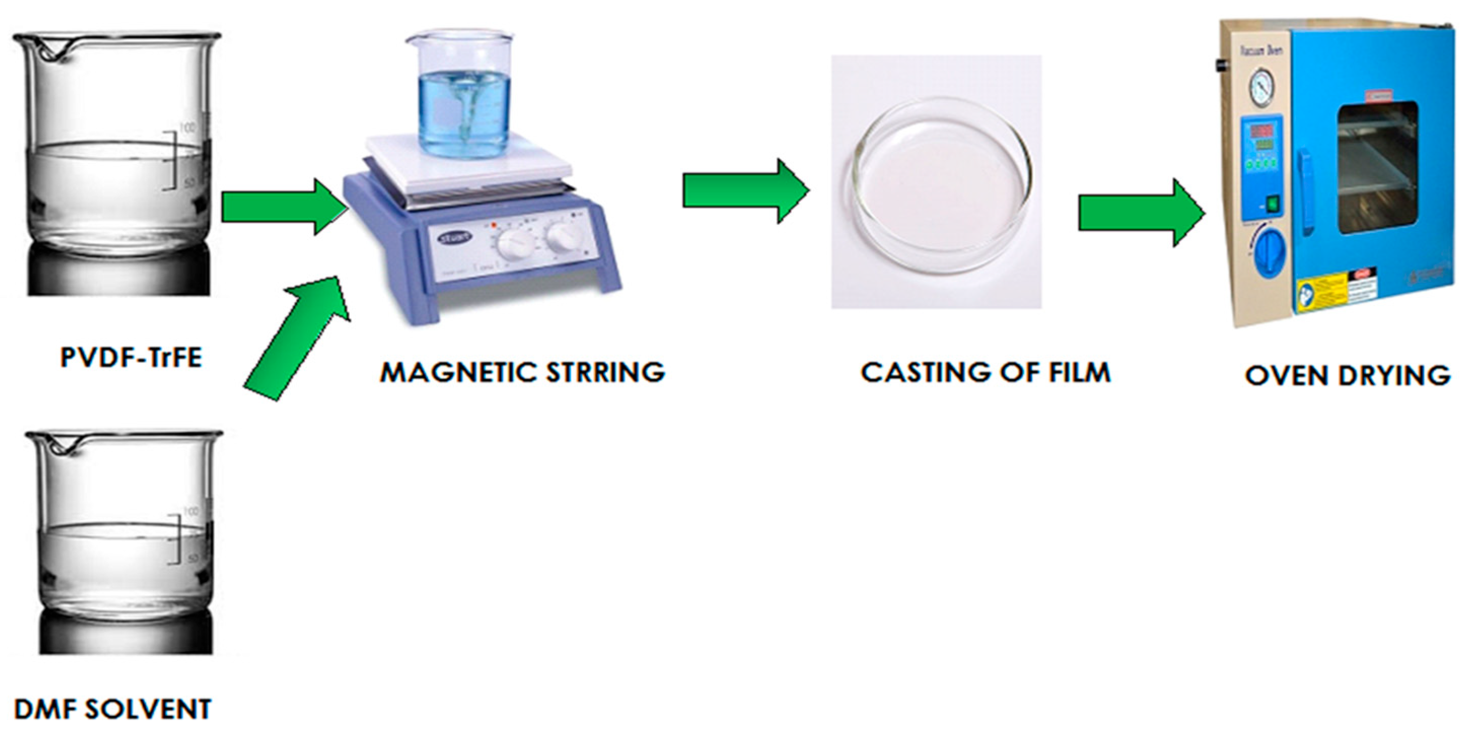
2.2. Composite Prepared from Solution Casting Method
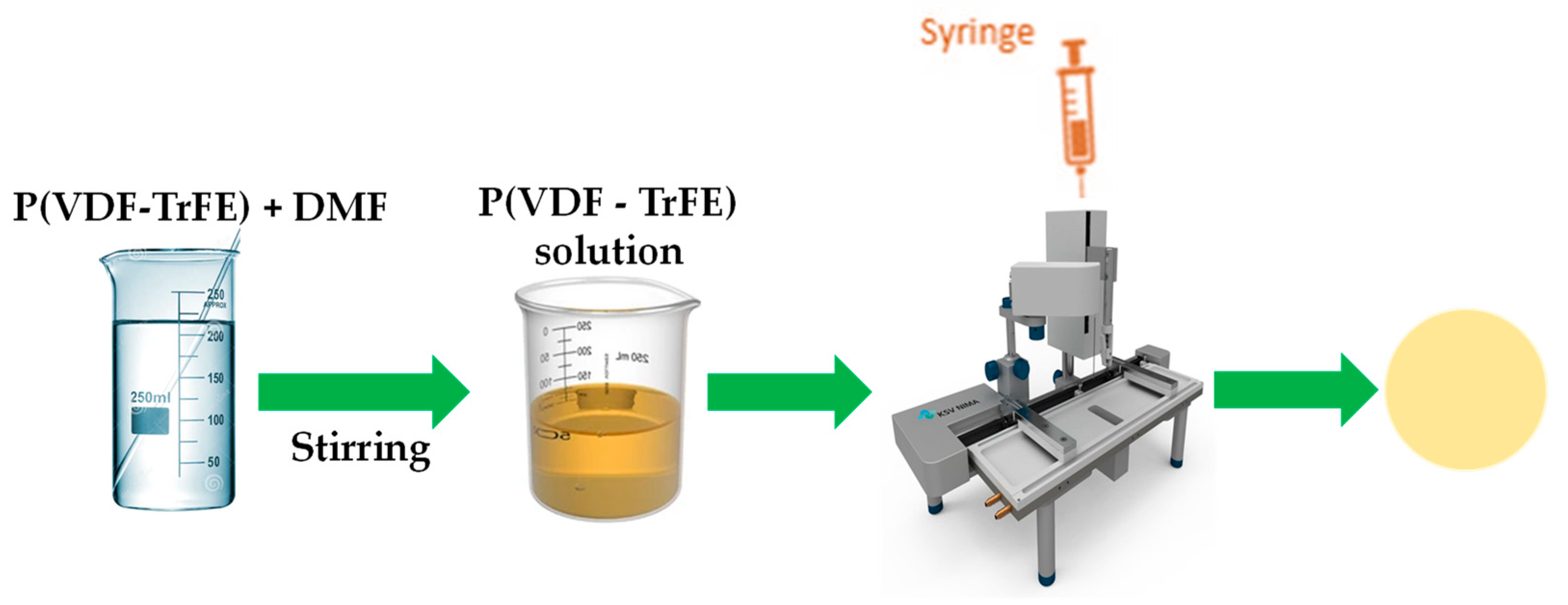
2.3. Composite Prepared from Langmuir–Blodgett Method
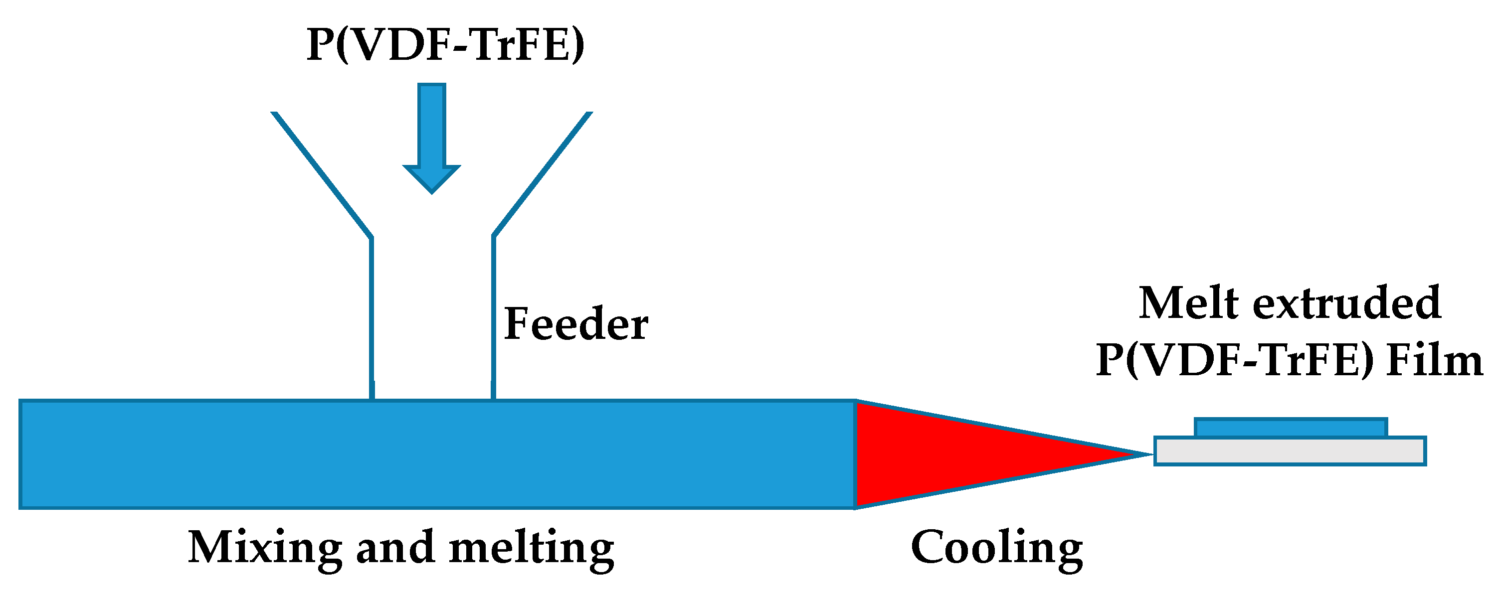
2.4. Composite Prepared from Melt Extrusion Method
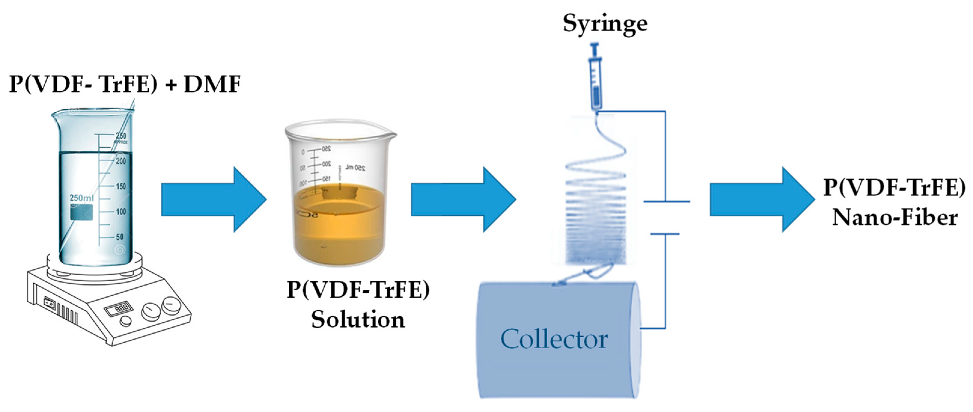
2.5. Composite Prepared from Electrospinning Method
3. Application of Piezoelectric P(VDF-TRFE) Composite
3.1. Energy Harvesting and Nanogenerators
3.2. Sensor Application
3.3. Biomedical Application
3.4. Transducer and Resonator
4. Conclusions and Future Scope
Author Contributions
Funding
Data Availability Statement
Conflicts of Interest
References
- Habib, M.; Lantgios, I. A review of ceramic, polymer and composite piezoelectric Materials. J. Phys. D Appl. Phys. 2022, 55, 423002. [Google Scholar] [CrossRef]
- Santucci, S.; Esposito, V. Electrostrictive Ceramic and their application. In Encyclopedia of Materials: Technical Ceramics and Glasses; Pomeroy, M., Ed.; Elsevier: Amsterdam, The Netherlands, 2021; Volume 3, pp. 369–374. [Google Scholar]
- Lipsa, L.; Rajput, S.; Parida, S.; Ghosh, S.P.; Verma, S.K.; Gupta, S. Influence of Hot-press Temperature on β-phase Formation and Electrical Properties of Solvent Casted PVDF-HFP Co-Polymer Films Prepared from Two Different Solvents: A Comparison Study. Macromol. Chem. Phys. 2023, 224, 2300204. [Google Scholar] [CrossRef]
- Abbasipour, M.; Khajavi, R. A comprehensive review on piezoelectric polymeric and ceramic nano generators. Adv. Eng. Mater. 2022, 24, 2101312. [Google Scholar] [CrossRef]
- Muduli, S.P.; Parida, S.; Behura, S.K.; Rajput, S.; Rout, S.K.; Sareen, S. Synergistic effect of graphene on dielectric and piezoelectric characteristic of PVDF-(BZT-BCT) composite for energy harvesting applications. Polym. Adv. Tech. 2022, 33, 3628–3642. [Google Scholar] [CrossRef]
- Eltouby, P.; Shyha, I.; Li, C.; Khaliq, J. Factors affecting the piezoelectric performance of ceramic-polymer composites: A comprehensive Review. Ceram. Int. 2021, 47, 17813–17825. [Google Scholar] [CrossRef]
- Rajput, S.; Parida, S.; Sharma, A.; Sonika. Dielectric Materials for Energy Storage and Energy Harvesting Devices; River Publishers: Aalborg, Denmark, 2023; Available online: https://ieeexplore.ieee.org/book/10177830 (accessed on 1 October 2023).
- Zielinski, T.G. Fundamentals of multiphysics modeling of piezo-poro-elastic structures. Arch. Mech. 2010, 62, 343–378. [Google Scholar]
- Stefanescu, D.M. Handbook of Force Transducer Principles and Components; Springlar: Berlin, Germany, 2011. [Google Scholar]
- Uchino, K. (Ed.) The Development of piezoelectric materials and the new perceptive. In Advanced Piezoelectric Materials, 2nd ed.; Woodhead Publishing: Swaston, UK, 2017; pp. 1–92. [Google Scholar]
- Rajput, S.; Sharma, A.; Jately, V.; Ram, M. Recent Advances in Energy Harvesting Technologies; River Publishers: Aalborg, Denmark, 2023; ISBN 978-8770228459. e-ISBN 978-8770228800. [Google Scholar] [CrossRef]
- Lewiner, J. Paul Langevin and the birth of ultrasonics. Jpn. J. Appl. Phys. 1991, 30, 5. [Google Scholar] [CrossRef]
- Camargo-Chavez, J.E.; Arceo-Diaz, S.; Bricio-Barrios, E.E.; Chavez-Valdez, R.E. Piezoelectric mathematical modeling, technological feasibility in the generation and storage of electric charges. Phys. Conf. Ser. 2022, 2159, 012009. [Google Scholar] [CrossRef]
- Khanbareh, H.; Rasheed, A.; Khaliq, J. 13—Piezoelectric composites. In Organic Ferroelectric Material and Application; Asadi, K., Ed.; Woodhead Publishing: Swaston, UK, 2022; pp. 457–475. [Google Scholar]
- Mishra, S.; Unnikrishnan, L.; Nayak, S.K.; Mohanty, S. Advances in piezoelectric polymer composites for energy harvesting applications. A systematic Review. Macromol. Mater. Eng. 2019, 304, 1800463. [Google Scholar] [CrossRef]
- Kawai, H. The Piezoelectricity of PVDF. Jpn. J. Appl. Phys. 1969, 8, 975. [Google Scholar] [CrossRef]
- Xin, Y.; Zhu, J.; Sun, H.; Xu, Y.; Liu, T.; Qian, C. A brief review on piezoelectric PVDF nanofibers prepared by electrospinning. Ferroelectrics 2018, 526, 140–151. [Google Scholar] [CrossRef]
- Ueberschlag, P. PVDF piezoelectric polymer. Sens. Rev. 2001, 21, 118–125. [Google Scholar] [CrossRef]
- Kabir, E.; Khatun, M.; Nasrin, L.; Raihan, M.J.; Rahman, M. Pure β-phase formation in polyvinylidene fluoride (PVDF)-carbon nanotube composites. J. Phys. D Appl. Phys. 2017, 50, 163002. [Google Scholar] [CrossRef]
- Sonika; Verma, S.K.; Samanta, S.; Srivastava, A.K.; Biswas, S.; Alsharabi, R.M.; Rajput, S. Conducting Polymer Nanocomposite for Energy Storage and Energy Harvesting Systems. Adv. Mater. Sci. Eng. 2022, 2022, 2266899. [Google Scholar] [CrossRef]
- Dallaev, R.; Pisarenko, T.; Sobola, D.; Orudzhev, F. Brief Review of PVDF properties and application. Polymers 2022, 14, 4793. [Google Scholar] [CrossRef]
- Wua, L.; Jing, M.; Liua, Y.; Ning, H.; Liu, X.; Liu, S.; Lina, L.; Hu, N.; Liu, L. Power generation by PVDF-TrFE/graphene nanocomposite films. Compos. Part B Eng. 2019, 164, 703–709. [Google Scholar] [CrossRef]
- Mokhtari, F.; Latifi, M.; Shamshirsaz, M. Electrospinning/electrospray of polyvinylidene fluoride (PVDF): Piezoelectric nanofibers. J. Text. Inst. 2016, 107, 1037–1055. [Google Scholar] [CrossRef]
- Salimi, A.; Yousefi, A.A. FTIR studies of β-phase crystal formation in stretched PVDF films. Polym. Test 2003, 22, 699–704. [Google Scholar] [CrossRef]
- Correia, H.M.G.; Ramos, M.M.D. Quantum modelling of poly (vinylidene fluoride). Comput. Mater. Sci. 2005, 33, 224–229. [Google Scholar] [CrossRef]
- Martins, P.; Lopes, A.C.; Lanceros-Mendez, S. Electroactive phases of poly(vinylidene fluoride): Determination, processing and applications. Prog. Polym. Sci. 2014, 39, 683–706. [Google Scholar] [CrossRef]
- Kim, Y.; Xie, Y.; Wen, X.; Wanga, S.; Kim, S.J.; Song, H.; Wanga, Z. Highly porous piezoelectric PVDF membrane as effective lithium ion transfer channels for enhanced self-charging power cell. Nano Energy 2014, 14, 77–86. [Google Scholar] [CrossRef]
- Broadhurst, M.G.; Davis, G.T. Physical basis for piezoelectricity in PVDF. Ferroelectrics 1984, 60, 3–13. [Google Scholar] [CrossRef]
- Cardoso, V.F.; Minas, G.; Costa, C.M.; Tavares, C.J.; Lanceros-Mendez, S. Micro and nano films of poly (vinylidene fluoride) with controlled thickness, morphology and electroactive crystalline phase for sensor and actuator applications. Smart Mater. Struct. 2021, 20, 087002. [Google Scholar] [CrossRef]
- Muduli, S.; Parida, S.; Rout, S.; Rajput, S.; Kar, M. Effect of hot press temperature on-phase, dielectric and ferroelectric properties of solvent casted Poly(vinyledene fluoride) films. Mater. Res. Exp. 2019, 6, 095306. [Google Scholar] [CrossRef]
- Pramod, K.; Gangineni, R.B. Influence of solvent evaporation rate on crystallization of poly (vinylidene fluoride) thin films. Bull. Mater. Sci. 2015, 38, 1093–1098. [Google Scholar] [CrossRef]
- Naik, R.; Rao, T.S. Preparation and characterization of flexible PVDF based polymer film for energy harvesting applications. Mater. Today Proc. 2019, 18, 5107–5113. [Google Scholar] [CrossRef]
- Gregorio, R., Jr.; Capitão, R.C. Morphology and phase transition of high melt temperature crystallized poly (vinylidene fluoride). J. Mater. Sci. 2000, 35, 299–306. [Google Scholar] [CrossRef]
- Gregorio, R., Jr.; Ueno, E.M. Effect of crystalline phase, orientation and temperature on the dielectric properties of poly (vinylidene fluoride) (PVDF). J. Mater. Sci. 1999, 34, 4489–4500. [Google Scholar] [CrossRef]
- Furukawa, T. Ferroelectric properties of vinylidene fluoride copolymers. Phase Transit. 1989, 18, 143–211. [Google Scholar] [CrossRef]
- Nalwa, H.S. Crystal Structure and Phase Transistion of PVDF and Related Copolymers. In Ferroelectric Polymers Chemistry, Physics and Applications, 1st ed.; Nalwa, H.S., Ed.; Marcel Dekker, Inc.: New York, NY, USA, 1995; pp. 63–181. [Google Scholar]
- Reynolds, N.M.; Kim, K.J.; Chang, C.; Hsu, S.L. Spectroscopic analysis of the electric field induced structural changes in vinylidene fluoride/trifluoroethylene copolymers. Macromolecules 1989, 22, 1092–1100. [Google Scholar] [CrossRef]
- Kobayashi, M.; Tashiro, K.; Tadokoro, H. Molecular vibrations of three crystal forms of poly(vinylidene fluoride). Macromolecules 1975, 8, 158–171. [Google Scholar] [CrossRef]
- Chisca, S.; Sava, I.; Musteata, V.; Bruma, M. Dielectric and conduction properties of polyimide films. In Proceedings of the IEEE International Semiconductor Conference, Sinaia, Romania, 17–19 October 2011; IEEE: Piscataway, NJ, USA, 2011. [Google Scholar]
- Kuang, D.; Li, R.; Pei, J. Polyamide 11/Poly(vinylidene fluoride)/Vinyl Acetate-Maleic Anhydride Copolymer as Novel Blends Flexible Materials for Capacitors. Polymer 2014, 6, 2146–2156. [Google Scholar] [CrossRef]
- Zhao, C.; Hong, Y.; Chu, X.; Dong, Y.; Hu, Z.; Sun, X.; Yan, S. Enhanced ferroelectric properties of P(VDF-TrFE) thin film on single layer graphene simply adjusted by crystallization condition. Mater. Today Energy 2021, 20, 100678. [Google Scholar] [CrossRef]
- Wu, T.; Jin, H.; Dong, S.; Xuan, W.; Xu, H.; Lu, L.; Fang, Z.; Huang, S.; Tao, X.; Shi, L.; et al. A Flexible Film Bulk Acoustic Resonator Based on β-Phase Polyvinylidene Fluoride Polymer. Sensors 2020, 20, 1346. [Google Scholar] [CrossRef]
- Veved, A.; Ejuh, G.W.; Djongyang, N. Review of emerging materials for PVDF based energy harvesting. Energy Rep. 2022, 8, 12853–12870. [Google Scholar] [CrossRef]
- Zhang, W.; Zaarour, B.; Zhu, L.; Huang, C.; Xu, B.; Jin, X. A comparitative study of electrospun polyvinylidene fluoride and polyv(inylidenefluoride-co-fluoroethylene)fiber webs:Mechanical properties, crystallinity and piezoelectric properties. J. Eng. Fibers Fabr. 2020, 15, 1–8. [Google Scholar]
- Wu, L.; Jin, Z.; Liu, Y.; Ning, H.; Liu, X.; Alamusi; Hu, N. Recent advances in the preparation of PVDF-based piezoelectric material. Nanotechnol. Rev. 2022, 11, 0082. [Google Scholar] [CrossRef]
- Wang, J.L.; Meng, X.J.; Chu, J.H. New Properties and Applications of Polyvinylidene Based Ferroelectric Polymer; Barranco, A.P., Ed.; Intech Open: London, UK, 2015; pp. 151–171. [Google Scholar]
- Shafee, E.E.; Behery, S.M. Preparation, characterization and properties of novel 0–3 ferroelectric composites of Ba0.95Ca0.05Ti0.8Zr0.2O3–poly(vinylidene fluoride-trifluoroethylene. Mater. Chem. Phys. 2012, 132, 740–746. [Google Scholar] [CrossRef]
- Sheng, Y.; Zhang, X.; Ye, H.; Liang, L.; Xu, L.; Wu, H. Improved energy density in core–shell poly(dopamine) coated barium titanate/poly(fluorovinylidene-co-trifluoroethylene) nanocomposite with interfacial polarization. Colloids Surf. B 2020, 585, 124091. [Google Scholar] [CrossRef]
- Nunes-Pereira, J.; Martins, P.; Cardoso, V.F.; Costa, C.M.; Lanceros-Mendez, S. A green solvent strategy for the development of piezoelectric poly(vinylidene fluoride–trifluoroethylene) films for sensors and actuators application. Mater. Des. 2016, 104, 183–189. [Google Scholar] [CrossRef]
- Vacche, S.D.; Damjanovic, D.; Michaud, V.; Leterrier, Y. Interface-Dominated Time-Dependent Behavior of Poled Poly (Vinylidene Fluoride–Trifluoroethylene)/Barium Titanate Composites. Materials 2020, 13, 225. [Google Scholar] [CrossRef]
- Wang, J.; Li, Z.; Yan, Y.; Wang, X.; Zhang, Z. Improving Ferro-and Piezo-Electric Properties of Hydrogenized Poly(vinylidene fluoride-trifluoroethylene) Films by Annealing at Elevated Temperatures. Chin. J. Polym. Sci. 2016, 34, 649–658. [Google Scholar] [CrossRef]
- Qian, J.; Jiang, S.; Wang, Q.; Zheng, S.; Guo, S.; Yi, C.; Wang, J.; Wang, X.; Tsukagoshi, K.; Shi, Y.; et al. Unveiling the piezoelectric nature of polar α-phase P(VDF-TrFE) at quasi-two-dimensional limit. Sci. Rep. 2018, 8, 532. [Google Scholar] [CrossRef]
- Poulsen, M.; Sorokin, A.V.; Adenwalla, S.; Ducharme, S.; Fridkin, V.M. Effects of an external electric field on the ferroelectric-paraelectric phase transition in polyvinylidene fluoride-trifluoroethylene copolymer Langmuir-Blodgett films. J. Appl. Phys. 2008, 103, 034116. [Google Scholar] [CrossRef]
- Lindemann, W.R.; Philiph, R.L.; Chan, D.W.W.; Ayers, C.T.; Perez, E.M.; Beckman, C.P.; Strzalka, J.; Chaudhary, S.; Vaknin, D. Oriented Polyvinylidene Fluoride-Trifluoroethylene films by Langmuir-Blodgett deposition:A synchrotron X ray diffraction study. Phys. Chem. Chem. Phys. 2015, 17, 29335–29339. [Google Scholar] [CrossRef] [PubMed]
- Pecora, A.; Maiolo, L.; Maita, F.; Minotti, A. Flexible PVDF-TrFE pyroelectric sensor driven by polysilicon thin film transistor fabricated on ultra-thin polyimide substrate. Sens. Actuators Rep. 2012, 185, 39–43. [Google Scholar] [CrossRef]
- Taseng, H.J.; Tian, W.C.; Wu, W.C. P(VDF-TrFE) Polymer-Based Thin Films Deposited on Stainless Steel Substrates Treated Using Water Dissociation for Flexible Tactile Sensor development. Sensors 2013, 13, 14777–14796. [Google Scholar] [CrossRef] [PubMed]
- Mahd, R.I.; Gan, W.C.; Majid, W.H.A. Hot Plate Annealing at a Low Temperature of a Thin Ferroelectric P(VDF-TrFE) Film with an Improved Crystalline Structure for Sensors and Actuators. Sensors 2014, 14, 19115–19127. [Google Scholar] [CrossRef]
- Li, B.; Cai, C.; Liu, Y.; Wang, F.; Li, Q.; Zhang, P.; Deng, B.; Hou, P.; Liu, W. Ultrasensitive mechanical/thermal response of a PVDF-TrFE sensor with a tailored network inter connection interface. Nat. Commun. 2023, 14, 4000. [Google Scholar] [CrossRef] [PubMed]
- Sharma, T.; Je, S.; Gill, B.; Zhang, J.X.J. Patterning piezoelectric response of PVDF-TrFE based pressure sensor for catheter application. Sens. Actuators A 2012, 177, 87–92. [Google Scholar] [CrossRef]
- Marchiori, B.; Regal, S.; Arango, Y.; Delattre, R.; Blayac, S.; Ramuz, M. PVDF-TrFE based stretchable contact and non-contact temperature sensor for E-skin application. Sensors 2020, 20, 623. [Google Scholar] [CrossRef]
- Baur, C.; Zhou, Y.; Sipes, J.; Priya, S.; Voit, W. Organic, Flexible, Polymer Composites for High-Temperature Piezoelectric Applications. Energy Harvest. Syst. 2014, 1, 167–177. [Google Scholar] [CrossRef]
- Nalwa, H.S.; Watanabe, T.; Kakuta, A.; Mukoh, A.; Miyata, S. Second-order nonlinear optical properties of an aromatic polyurea exhibiting optical transparency down to 300 nm. Appl. Phys. Lett. 1993, 62, 3223–3225. [Google Scholar]
- Yoo, S.; Kim, D.G.; Ha, T.; Won, J.C.; Jang, K.S.; Kim, Y.H. Solution-Processable, Thin, and High-κ Dielectric Polyurea Gate Insulator with Strong Hydrogen Bonding for Low-Voltage Organic Thin-Film Transistors. Appl. Mater. Interfaces 2018, 10, 32462–32470. [Google Scholar] [CrossRef] [PubMed]
- Fitzgerald, E.R.; Miller, R.F. Dielectric properties of the system polyvinyl Chloride-Dimethylthianthrene. J. Colloid. Sci. 1953, 8, 148–169. [Google Scholar] [CrossRef]
- Kalimuldina, G.; Turdakyn, N.; Abay, I.; Medeubayev, A.; Nurpeissova, A.; Adair, D.; Bakenov, Z. A Review of Piezoelectric PVDF Film by Electro spinning and its Applications. Sensors 2020, 20, 5214. [Google Scholar] [CrossRef] [PubMed]
- Padurariu, L.; Brunengo, E.; Canu, G.; Curecheriu, L.P.; Conzatti, L.; Buscaglia, M.T.; Stagnaro, P.; Mitoseriu, L.; Buscaglia, V. Role of microstructures in the dielectric properties of PVDF-based nanocomposites containing high permittivity for energy storage. Appl. Mater. Interfaces 2023, 15, 13535–13544. [Google Scholar] [CrossRef]
- Sousa, R.E.; Ferreira, J.C.C.; Costa, C.M.; Machado, A.V.M.; Silva, M.; Lanceros-Mendez, S. Tailoring poly (vinylidene fluoride-co-chlorotrifluoroethylene) microstructure and physicochemical properties by exploring its binary phase diagram with dimethylformamide. J. Polym. Sci. Part B Polym. Phys. 2015, 53, 761–773. [Google Scholar] [CrossRef]
- Xiao, J.; Berlin, H.Z.; Zhou, X.; Zhang, Q.; Dowben, P.A. The effect of defects on the electronic structure of long chain ferroelectric polymers. J. Appl. Phys. 2009, 106, 044105. [Google Scholar] [CrossRef]
- Zhang, S.; Tong, W.; Wang, J.; Wang, W.; Wang, Y.; Zhang, Y. Modified sepiolite/PVDF-HFP composite film with enhanced piezoelectric and dielectric properties. J. Appl. Polym. Sci. 2020, 37, 48412. [Google Scholar] [CrossRef]
- Singh, B.; Kumar, R.; Cohan, J.S. Polymer matrix composites in 3D printing: A state of art review. Mater. Today Proc. 2020, 33, 1562–1567. [Google Scholar] [CrossRef]
- Apelt, S.; Hohne, S.; Mehner, E.; Bohm, C.; Malanin, M.; Eichhorn, K.; Jehnichin, D.; Uhlmann, P.; Bergmann, U. Poly (vinylidene fluoride-co-trifluoroethylene) thin films after dip and spin coating. Macromol. Mater. Eng. 2022, 307, 220296. [Google Scholar] [CrossRef]
- Lee, J.H.; Yoon, H.J.; Kim, T.Y.; Gupta, M.K.; Lee, J.H.; Seung, W.; Ryu, H.; Kim, S.W. Micropatterned P(VDF-TrFE) Film-Based Piezoelectric Nanogenerators for Highly Sensitive Self-Powered Pressure Sensors. Adv. Funct. Mater. 2015, 25, 3203–3209. [Google Scholar] [CrossRef]
- Muduli, S.P.; Lipsa, L.; Choudhary, A.; Rajput, S.; Parida, S. Modulation of Electrical Characteristics of Polymer-Ceramic-Graphene Hybrid Composite for Piezoelectric Energy Harvesting. ACS Appl. Electron. Mater. 2023, 5, 3023–3037. [Google Scholar] [CrossRef]
- Mahdi, R.I.; Gan, W.C.; Majid, W.H.A.; Mukri, N.I.; Furukawa, T. Ferroelectric polarization and pyroelectric activity of functionalized P(VDF-TrFE) thin film lead free nanocomposites. Polymer 2018, 141, 184–193. [Google Scholar] [CrossRef]
- Koner, S.; Deshmukh, P.; Ahlawat, A.; Karnal, A.K.; Satapathy, S. Studies on structural, dielectric, impedance spectroscopy and magnetodielectric properties of La0.7Ba0.3MnO3/P(VDF-TrFE) multiferroic (0–3) nanocomposite films. J. Alloys Compd. 2021, 868, 159104. [Google Scholar] [CrossRef]
- Mahdi, R.I.; Gan, W.C.; Halim, N.A.; Velayutham, T.S.; Majid, W.H.A. Ferroelectric and pyroelectric properties of novel Poly (vinylidene fluoride-trifluoroethylene-Bi0.5Na0.5TiO3 nanocomposite films for sensing applications. Ceram. Int. 2015, 41, 13836–13843. [Google Scholar] [CrossRef]
- Sebastian, M.T.; Jantunen, H. Polymer-Ceramic Composites of 0-3 connectivity for circuits in electronics: A review. Int. J. Appl. Ceram. Technol. 2010, 7, 415–434. [Google Scholar] [CrossRef]
- Uchino, K. 9-Piezoelectric composite materials. In Advanced Piezoelectric Material; Uchino, K., Ed.; Woodhead Publishing: Swaston, UK, 2010; pp. 318–346. [Google Scholar]
- Mammeri, F. Chapter 3—Nanostructured flexible PVDF and fluropolymer—Based hybrid films. In Frontiers of Nanoscience; Benelmekki, M., Erbe, A., Eds.; Elsevier: Amsterdam, The Netherlands, 2021; Volume 14, pp. 67–101. [Google Scholar]
- Spin Coating Overview. Available online: www.costeffectiveequipment.com/servicesupport/technical-resourses/spincoating-theory (accessed on 4 January 2023).
- Xia, K.; Li, Y.C.; Li, J.; Xie, B.; Zhao, C. Research on the effect of spin coating process on ferroelectric phase of P(VDF-TrFE)/ZnO film. In Proceedings of the IEEE Symposium on Piezoelectricity, Acoustic Waves and Applications, Xi’an, China, 27–30 October 2017; IEEE: Piscataway, NJ, USA, 2017. [Google Scholar]
- Dahan, R.; Arshad, A.N.; Razif, M.H.M.; Zohdi, N.S.N. Structural and electrical properties of PVDF-TrFE/ZnO bilayer and filled PVDF-TrFE/ZnO single layer nanocomposite films. Adv. Mater. Process. Technol. 2017, 3, 300–307. [Google Scholar]
- Lau, K.; Liu, Y.; Chen, H.; Withers, R.L. Effect of annealing temperature on the morphology and piezoresponse characterization of poly(vinylidene fluoride-trifluoroethylene) films via scanning probe Microscopy. Adv. Condens. Matter. Phys. 2013, 2013, 435938. [Google Scholar] [CrossRef]
- Rozana, M.D.; Wahid, M.H.; Arshad, A.N.; Sarip, M.N.; Habibah, Z.; Ismail, L.N.; Ruso, M. Effect of various annealing temperature on the morphological and dielectric properties of Polyvinylidenefluoride-Trifluoroethylene thin film. In Proceedings of the Symposium on Humanities Science and Engineering, Kuala Lumpur, Malaysia, 24–27 June 2012; IEEE: Piscataway, NJ, USA, 2012. [Google Scholar]
- Men, T.; Liu, X.; Jiang, B.; Long, X.; Guo, H. Ferroelectric β crystalline phase formation and property enhancement in Polydopamine modified BaTiO3/PVDF-TrFE nanocomposite. Thin Solid Film. 2019, 669, 579–587. [Google Scholar] [CrossRef]
- Chen, S.; Yao, K.; Tay, F.E.H.; Chew, L.L.S. Comparative investigation of the structure and properties of ferroelectric poly (vinylidene fluoride) and poly (vinylidene fluoride–trifluoroethylene) thin films crystallized on substrates. J. Appl. Polym. Sci. 2010, 116, 3331–3337. [Google Scholar] [CrossRef]
- Park, Y.J.; Kang, S.J.; Shin, Y.; Kim, R.H.; Bae, I.; Park, C. Non-volatile memory characteristics of epitaxially grown PVDF-TrFE thin films and their printed micropattern application. Curr. Appl. Phys. 2011, 11, 30–34. [Google Scholar] [CrossRef]
- Wahid, M.H.M. The Doctoral Research Abstracts; Institute of Graduate Studies, UiTM: Shah Alam, Malaysia, 2018. [Google Scholar]
- Mai, M.; Zhu, C.; Liu, G.; Ma, X. Effect of dielectric layer on ferroelectric responses of P(VDF-TrFE) thin films. Phys. Lett. A 2018, 382, 2372–2375. [Google Scholar] [CrossRef]
- Yang, J.H.; Ryu, T.; Lansac, Y.; Jang, Y.H. Shear stress-induced enhancement of the piezoelectric properties of PVDF-TrFE thin films. Org. Electron. 2016, 28, 67–72. [Google Scholar] [CrossRef]
- Nguyen, V.; Rouxel, D.; Vincent, B.; Badie, L.; Santos, F.D.D.; Lamouroux, E.; Fort, Y. Influence of cluster size and surface functionalization of ZnO nanoparticles on the morphology, thermomechanical and piezoelectric properties of P(VDF-TrFE) nanocomposite films. Appl. Surf. Sci 2013, 279, 204–211. [Google Scholar] [CrossRef]
- Zhu, R.; Jenkins, K.; Yang, R. Degradation and Nano-Patterning of Ferroelectric P(VDF-TrFE) Thin Films with Electron Irradiation. RSC Adv. 2015, 129, 106700–106705. [Google Scholar] [CrossRef]
- Zhang, Q.; Zhu, Z.; Shen, D.; Yang, H. Enhanced dielectric and hydrophobic properties of PDMS/P(VDF-TrFE) blend films by embedding PS microspheres. Colloids Surf. A 2019, 569, 171–178. [Google Scholar] [CrossRef]
- Yaqoob, U.; Chung, G.S. Effect of surface treated MWCNTs and BaTiO3 nanoparticle on the dielectric properties of a P(VDF-TrFE) Matrix. J. Alloys Compod. 2017, 695, 1231–1236. [Google Scholar] [CrossRef]
- Fortunato, M.; Tamburrano, A.; Bracciale, M.P.; Santarelli, M.L.; Sarto, M.S. Enhancement of the piezoelectric coefficient in PVDF-TrFE/CoFe2O4 nanocomposites through DC magnetic poling. Beilstein J. Nanotechnol. 2021, 12, 1262–1270. [Google Scholar] [CrossRef]
- Wang, J.C.; Jiang, Y.P.; Lin, Y.J.; Chan, S.H. Trifluoroethylene bond enrichment in P(VDF-TrFE) copolymers with enhanced ferroelectric behaviors by plasma fluorination on bottom electrode. J. Tiwan Inst. Chem. Eng. 2020, 107, 152–160. [Google Scholar] [CrossRef]
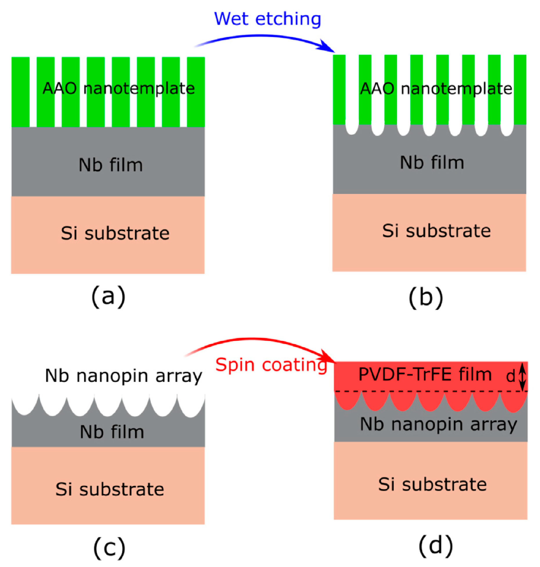
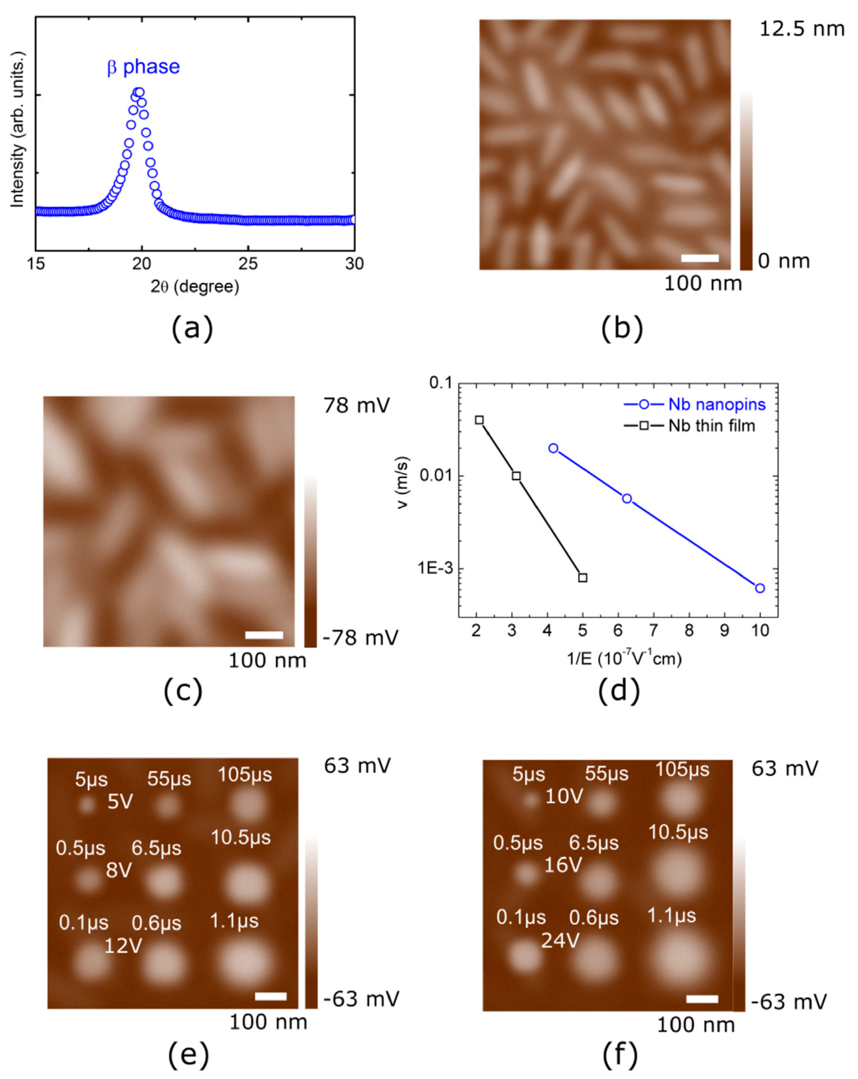
- Ahn, Y.; Son Yeog, J. Enhanced ferroelectric properties of P(VDF TrFE) thin films from Nb nano pin electrodes. Polymer 2019, 180, 121696. [Google Scholar] [CrossRef]
- Perez, J.; Vilarinho, P.M.; Kholkin, A.L. High-quality PbZr0.52Ti0.48O3 films prepared by modified sol-gel route at low temperature. Thin Solid Films 2004, 449, 20–24. [Google Scholar] [CrossRef]
- Losego, M.D.; Ihlefeld, J.F.; Maria, J.P. Importance of solution chemistry in preparing sol-gel. Chem. Mater. 2008, 20, 303–307. [Google Scholar] [CrossRef]
- Das, R.; Pattanayak, A.J.; Swain, S.K. Polymer-Based Nanocomposites for Energy and Environmental Application; Woodhead Publishing: Swaston, UK, 2018. [Google Scholar]
- Galiano, F. Casting Solution. In Encyclopedia of Membranes; Drioli, E., Giorno, L., Eds.; Mannheim Media: New York, NY, USA, 2020. [Google Scholar]
- Swain, S.K.; Pattanayak, A.J.; Sahoo, A.D. Functional Biopolymers; Thakur, V.K., Thakur, M.K., Eds.; Springer: Berlin/Heidelberg, Germany, 2017. [Google Scholar]
- Koner, S.; Deshmukh, P.; Khan, A.A.; Ahlawat, A.; Karnal, A.K.; Satapathy, S. Multiferroic properties of La0.7Ba0.3MnO3/P(VDF-TrFE) (0-3) nano-composite films. Mater Lett. 2020, 261, 127161. [Google Scholar] [CrossRef]
- Zhang, L.; Shan, X.; Wu, P.; Cheng, Z.-Y. Dielectric characteristics of CaCu3Ti4O12/P(VDF-TrFE) nanocomposites. Appl. Phys. A 2012, 107, 597–602. [Google Scholar] [CrossRef]
- Bystrov, V.S.; Bdikin, I.K.; Kiselev, D.A.; Yudin, S.; Fridkin, V.M.; Kholkin, A.L. Nanoscale polarization patterning of ferroelectric Langmuir-Blodgett P(VDF-TrFE) films. J. Phys. D Appl. Phys. 2007, 40, 4571. [Google Scholar] [CrossRef]
- Petty, M.; Tsibouklis, J.; Davis, F.; Hodge, P.; Petty, M.C.; Feast, W.J. Pyroelectric Langmuir-Blodgett films prepared using preformed polymers. J. Phys. D Appl. Phys. 1992, 25, 1032. [Google Scholar] [CrossRef]
- Newnham, R.E. Properties of Materials. In Anisotropy, Symmetry, Structure; University Press: Oxford, NY, USA, 2004. [Google Scholar]
- Breitenbach, J. Melt Extrusion: From process to drug delivery technology. Eur. J. Pharm. Biopharm. 2002, 54, 107–117. [Google Scholar] [CrossRef]
- Nelson, K.D. Absorbable, drug-loaded, extruded fiber for implantation. In Biomedical Textiles for Orthopedic and Surgical Applications; Woodhead Publishing: Sawston, UK, 2005; pp. 119–143. [Google Scholar]
- Meng, N.; Zhu, X.; Mao, R.; Reece, M.J.; Bilotti, E. Nanoscale Interfacial Electroactivity in PVDF/PVDF-TrFE Blended Films with Enhanced Dielectric and Ferroelectric. J. Mater. Chem. C 2017, 13, 3296–3305. [Google Scholar] [CrossRef]
- Meng, N.; Ren, X. Multiscale understanding of electric polarization in PVDF based ferroelectric Polymers. J. Mater. Chem. C 2020, 46, 16436–16442. [Google Scholar] [CrossRef]
- Beringar, L.T.; Xu, X.; Shih, W.; Shih, W.; Habas, R.; Schauer, C. An electrospun PVDF-TrFE fiber sensor platform for biological applications. Sens. Actuators A 2015, 222, 293–300. [Google Scholar] [CrossRef]
- Kim, Y.; Wu, X.; Lee, C.; Oh, J.H. Characterization of PI/PVDF-TrFE composite nanofiber based Triboelectric nanogenerators depending on the type of the electrospinning system. ASC Appl. Mater. Interfaces 2021, 13, 31. [Google Scholar] [CrossRef] [PubMed]
- Pourbafrani, M.; Azimi, S.; Nia, N.Y.; Zendehdel, M.; Abolhasani, M.M. The effect of electrospinning parameters on piezoelectric PVDF-TrFE nanofibers:Experimental and simulation study. Energies 2023, 16, 37. [Google Scholar] [CrossRef]
- Jiang, Y.G.; Sun, X.J.; Zhang, D.Y. Highly allignedP(VDF-TrFE) nano fibers with anisotropic piezoelectricity fabricated by electrospinning for physical sensing device. In Proceedings of the IEEE International Conference on Solid State Sensors, Actuators and Micro Systems, Anchorage, AK, USA, 21–25 June 2015; IEEE: Piscataway, NJ, USA, 2015. [Google Scholar]
- Ico, G.; Showalter, A.; Bosze, W.; Gott, S.C.; Kim, B.S.; Rao, M.P.; Myung, N.V.; Nam, J. Size dependent piezoelectric and mechanical properties of electrospun P(VDF-TrFE) nanofibers for enhanced energy harvesting. J. Mater. Chem. A 2016, 4, 2293–2304. [Google Scholar] [CrossRef]
- Kibria, F.; Rahman, W. Electrospinning based high sensitive PVDF-TrFE nanofiber sensor with sensitivity dependence on pore diameter. Curr. Sci. 2020, 119, 5. [Google Scholar] [CrossRef]
- Ahmed, A.; Jia, J.; Huang, Y.; Khoso, N.A.; Deb, H.; Fan, Q.; Shao, J. Preparation of PVDF-TrFE based electrospun nanofibers decorated with PEDOT-CNT/rGO Composites for piezo electric pressure sensor. J. Mater. Sci. Mater. Electron. 2019, 30, 14007–14021. [Google Scholar] [CrossRef]
- Kang, H.B.; Han, C.S.; Pyun, J.C.; Ryu, W.H.; Kang, C.Y.; Cho, Y.S. (Na, K)NbO3 nanoparticle-embedded piezoelectric nanofiber composites for flexible nanogenerators. Compos. Sci. Technol. 2015, 111, 1–8. [Google Scholar] [CrossRef]
- Liu, K.; Choi, H.J.; Kim, B.K.; Kim, D.B.; Han, C.S.; Kim, S.W.; Kang, H.B.; Park, J.W.; Chao, Y.S. Piezoelectric energy harvesting and charging performance of Pb(Zn1/3Nb2/3)O3–Pb(Zr0.5Ti0.5)O3 nanoparticle-embedded P(VDF-TrFE) nanofiber composite sheets. Compos. Sci. Technol. 2018, 168, 296–302. [Google Scholar] [CrossRef]
- Liu, J.; Yang, B.; Lu, L.; Wang, X.; Li, X.; Chen, X.; Liu, J. Flexible and lead-free piezoelectric nanogenerator as self-powered sensor based on electro spinning BZT-BCT/P(VDF-TrFE)nanofibers. Sens. Actuators A 2020, 303, 111796. [Google Scholar] [CrossRef]
- Wang, X.; Yang, B.; Liu, J.; Zhu, Y.; Yang, C.; He, Q. A flexible triboelectric piezoelectric hybrid nanogenerator based on PVDF-TrFE nanofibers and PDMS/MWCNT for wearable device. Sci. Rep. 2006, 6, 36409. [Google Scholar] [CrossRef]
- Turdakyn, N.; Bekezhankyzy, Z.; Araby, S.; Montazami, R.; Bakenov, Z.; Kalimuldina, G. Investigation of electrospun piezoelectric P(VDF-TrFE) nanofiber-based nanogenerators for energy harvesting. Energy Rep. 2023, 10, 628–636. [Google Scholar] [CrossRef]
- Serairi, L.; Gu, L.; Qin, Y.; Lu, Y.; Basset, P.; Wang, Y.L. Flexible piezoelectric nanogenerators based on PVDF-TrFE nanofibers. Eur. Phys. J. Appl. Phys. 2017, 80, 30901. [Google Scholar] [CrossRef]
- Topark, A.; Tigil, O. Micron scale energy harvesters using multiple piezoelectric polymer layers. Sens. Actuators A 2018, 269, 412–418. [Google Scholar] [CrossRef]
- Kim, S.; Towfeeq, I.; Dong, Y.; Gorman, S.; Rao, A.M.; Koley, J. P(VDF-TrFE) Film on PDMS Substrate for Energy Harvesting Applications. Appl. Sci. 2018, 8, 213. [Google Scholar] [CrossRef]
- Habibur, R.M.; Yaqoob, U.; Muhammad, S.; Uddin, A.S.M.; Kim, H.C. The effect of RGO on dielectric and energy harvesting properties of P(VDF-TrFE) matrix by optimizing electro active β phase without traditional polling process. Mater. Chem. Phys. 2018, 215, 46–55. [Google Scholar] [CrossRef]
- Kim, Y.; Kim, D.; Jung, J.; Kim, S.W.; Kim, M. Airflow induced P(VDF-TrFE) fiber arrays for enhanced piezoelectric harvesting. APL Mater. 2022, 10, 031110. [Google Scholar] [CrossRef]
- Kullukcu, B.; Beker, L. Design and modeling of a PVDF-TrFE flexible wind energy harvesters. Turk. J. Electr. Eng. Comput. Sci. 2023, 31, 6. [Google Scholar] [CrossRef]
- Zhang, Q.Q.; Chan, H.L.W.; Ploss, B.; Choy, C.L. PCLT/P(VDF-TrFE) nanocomposite pyroelectric sensors. IEEE Trans. Ultrason. Ferroelectr. Freq. Control 2001, 48, 154–160. [Google Scholar] [CrossRef]
- Wang, S.; Shao, H.Q.; Liu, Y.; Tang, C.Y.; Zhao, X.; Ke, K.; Bao, R.K.; Yang, M.B.; Yang, W. Boosting piezoelectric response of PVDF-TrFE via Mxene for self-powered linear pressure sensor. Compos. Sci. Technol. 2021, 202, 108600. [Google Scholar] [CrossRef]
- Gupta, S.; Shaktthivel, D.; Lorenzelli, L.; Dahiya, R. Temperature compensated tactile sensing using MOSFET with PVDFTrFE/BaTiO3 capacitor as extended gate. IEEE. Sens. J. 2019, 19, 435–442. [Google Scholar] [CrossRef]
- Nazir, N.A.; Kim, N.; Iglesias, W.G.; Jakli, A.; Kyu, T. Conductive behavior in relation to domain morphology and phase diagram of Nafion/poly (vinylidene-co-trifluoroethylene) blends. Polymer 2012, 53, 196–204. [Google Scholar] [CrossRef]
- Simoes, R.D.; Rodriguez-Perez, M.A.; De Saja, J.A.; Constantino, C.J.L. Tailoring, the structural properties of PVDF and P(VDF-TrFE) by using natural polymers as additives. Poly. Eng. Sci. 2009, 49, 2150–2157. [Google Scholar] [CrossRef]
- Li, Y.; Liao, C.; Tjnog, S.C. Electrospun polyvinylidene fluoride based fibrous scaffolds with piezoelectric characteristics for bone and neural tissue engineering. Nanaomaterials 2019, 9, 952. [Google Scholar] [CrossRef] [PubMed]
- Orkwis, J.A.; Wolf, A.K.; Mularczyk, Z.J.; Bryan, A.E.; Smith, C.S.; Brown, R.; Krutko, M.; McCann, A.; Collar, R.M.; Esfandiari, L.; et al. Mechanical stimulation of a bioactive, functionalized PVDF-TrFE scaffold provides electrical signaling for nerve repair application. Biomater. Adv. 2022, 140, 213081. [Google Scholar] [CrossRef] [PubMed]
- Adadi, N.; Yadid, M.; Gai, I.; Asulin, M.; Feiner, R.; Edri, R.; Dvir, T. Electrospun fibrous PVDF-TrFE scaffolds for cardiac tissue engineering, differentiation and maturation. Adv. Mater. Technol. 2020, 5, 1900820. [Google Scholar] [CrossRef]
- Ohigashi, H.; Koyama, H.K.; Takahashi, S.; Ishizaki, A.; Maida, Y. Piezoelectric Properties of P(VDF-TrFE) Thin Films at Low Temperatures and Their Application to Ultrasonic Transducers for Scanning Acoustic Microscopy Operating in a Wide Temperature Range. Jpn. J. Appl. Phys. 1989, 28, 28–66. [Google Scholar] [CrossRef]
- Ducrot, P.H.; Dufour, I.; Ayela, C. Optimization of PVDF-TrFE Processing Conditions for The Fabrication of Organic MEMS Resonators. Sci. Rep. 2016, 6, 19426. [Google Scholar] [CrossRef]
- Kanek, R.; Froemel, J.; Tanaka, S. Development of PVDF-TrFE/SiO2 composite film bulk acoustic resonator. Sens. Actuator A 2018, 284, 120–128. [Google Scholar] [CrossRef]
- Takahashi, S. Properties and characteristics of P(VDF/TrFE) transducers manufactured by a solution casting method for use in the MHz-range ultrasound in air. Ultrasonics 2012, 52, 422–426. [Google Scholar] [CrossRef]
- Jung, S.W.; Yoon, S.M.; Kang, S.Y.; You, I.K.; Koo, J.B.; Baeg, K.J.; Noh, Y.Y. Low-voltage-operated top-gate polymer thin-film transistors with high-capacitance P(VDF-TrFE)/PVDF-blended dielectrics. Curr. Appl. Phys. 2011, 11, S213–S218. [Google Scholar] [CrossRef]
- Sahoo, R.; Mishra, S.; Unnikrishnan, L.; Mohanty, S.; Mahapatra, S.; Nayak, S.K.; Anwar, L.; Ramadoss, A. Enhanced dielectric and piezoelectric properties of Fe doped ZnO/PVDF-TrFE composite films. Mater. Sci. Semicond. Process 2020, 117, 105173. [Google Scholar] [CrossRef]
- Sahoo, R.; Mishra, S.; Ramadoss, A.; Mohanty, S.; Mahapatra, S.; Nayak, S.K. An approach towards the fabrication of energy harvesting device using Ca doped ZnO/PVDF-TrFE composite film. Polymer 2020, 205, 122869. [Google Scholar] [CrossRef]
- Kim, J.H.; Kim, B.; Kim, S.W.; Kang, H.W.; Park, M.C.; Park, D.H.; Ju, B.K.; Choi, W.K. High performance coaxial piezoelectric energy generator (C-PEG) yarn of Cu/PVDF-TrFE/PDMS/Nylon/Ag. Nanotechnology 2021, 32, 145401. [Google Scholar] [CrossRef] [PubMed]
- Aliane, A.; Benwadih, M.; Bouthinon, B.; Coppard, R.; Santos, F.D.D.; Daami, A. Impact of crystallization on ferro, piezo and pyro electric characteristics in thin film P(VDF-TrFE). Org. Electron. 2015, 25, 92–98. [Google Scholar] [CrossRef]
- Gosh, S.K.; Roy, K.; Mishra, H.K.; Sahoo, M.R.; Mohanty, B.; Vishwakarma, P.N.; Mandal, D. Rollable Magnetoelectric energy harvestors as wireless IOT sensor. ACS Sustain. Chem. Eng. 2020, 8, 864–873. [Google Scholar] [CrossRef]
- Sun, Q.Q.; Xia, W.M. The dependence of acoustic emission on the crystal structures, dielectric, ferroelectric and piezoelectric properties of P(VDF-TrFE) sensors. IEEE Trans. Ultrason. Ferroelectro. Freq. Control 2020, 67, 975–983. [Google Scholar] [CrossRef]
- Wen, D.; Chen, X.; Huang, F.; Zhang, J.; Yang, P.; Li, R.; Lu, Y.; Liu, Y. Piezoelectric and magnetoelectric effects of flexible magnetoelectric heterostructure PVDF-TrFE/FeCoSiB. Int. J. Mol. Sci. 2022, 23, 15992. [Google Scholar] [CrossRef]
- Ummer, R.P.; Raneesh, B.; Thevenot, C.; Rouxel, D.; Thomas, S.; Kalarikkal, N. Electric, Magnetic, Piezoelectric and Magnetoelectric studies of phase pure (BiFeO3-NaNbO3)-P(VDF-TrFE) nanocomposites prepared by spin coating. RSC Adv. 2016, 6, 28069–28080. [Google Scholar] [CrossRef]
- Li, J.W.; Huang, C.Y.; Chen, K.Y.; Chen, J.X.; Hsu, X.Y.; Chen, Y.F.; Kuo, C.F.J.; Cheng, C.C.; Snen, M.C.; Chiu, C.W. Enhanced piezoelectric properties of poly(vinylidenefluoride-co-trifluoroethylene)/carbon based nanomaterial composite films for pressure sensing application. Polymers 2020, 12, 2999. [Google Scholar] [CrossRef]
- Yao, L.; Zhang, Z.; Zhang, Q.; Zhou, Z.; Yang, H.; Chen, L. Modified organic polystyrene microspheres embedded into PVDF-TrFE with lotus leaf microstructure enables high performance triboelectric nanogenerator. Nano Energy 2021, 86, 106128. [Google Scholar] [CrossRef]
- Wang, A.; Hu, M.; Zhou, L.; Qiang, X. Self powered well aligned PVDF-TrFE piezoelectric nanofiber nanogenerator for modulating an exact electrical stimulation and enhancing the proliferation of presteoblasts. Nanaomaterials 2019, 9, 349. [Google Scholar] [CrossRef] [PubMed]
- Jiang, Y.P.; Yang, T.C.; Lin, T.H.; Ho, C.M.; Chan, S.H.; Wu, M.C.; Wang, J.C. Layer dependent solvent vapor annealing on stacked ferroelectric PVDF-TrFE copolymers for highly efficient nanogenerator applications. Polymer 2020, 204, 122822. [Google Scholar] [CrossRef]
- Han, J.; Kim, J.H.; Choi, H.J.; Kim, S.W.; Sung, S.M.; Kim, M.S.; Choi, B.K.; Paik, J.H.; Lee, J.S.; Cho, Y.S. Origin of enhanced piezoelectric energy harvesting in all polymer based core shell nanofibers with controlled shell thickness. Compos. Part B 2021, 223, 109141. [Google Scholar] [CrossRef]
- Hernandez, N.; Gonzalez, V.G.; Bautista, D.; Soto, N.O.; Barandiaran, J.M.; Gutierrez, J. Electrospun poly (vinylidene fluoride-trifluoroethylene) based flexible magnetoelectric nanofibers. Eur. Polym. J. 2018, 109, 336–340. [Google Scholar] [CrossRef]
- Toprak, A. MEMS Scale PVDF-TrFE based piezoelectric energy harvesters. J. Microelectromech. Syst. 2015, 24, 1989–1997. [Google Scholar] [CrossRef]
- Toprak, A.; Tigli, O. Comprehensive characterization of PVDF-TrFE thin films for microelectromechanical system application. J. Mater. Sci. Mater. Electron. 2017, 28, 15877–15885. [Google Scholar] [CrossRef]
- Hu, X.; You, M.; Yi, N.; Zhang, X.; Xiang, Y. Enhanced piezoelectric coefficient of PVDF-TrFE films via in situ polarization. Front. Energy Res. 2021, 9, 621540. [Google Scholar] [CrossRef]
- Ahn, G.; Kim, S.R.; Choi, Y.-Y.; Song, H.W.; Sung, T.H.; Hong, J.; No, K. Facile preparation of ferroelectric poly (vinylidene fluoride co trifluoroethylene) thick films by solution casting. Polym. Eng. Sci. 2014, 54, 466–471. [Google Scholar] [CrossRef]
- Disnan, D.; Hafner, J.; Schneider, M.; Schmid, U. Spherulite like microstructure observed for spin cast P(VDF-TrFE) thin films and their ferroelectric characterization. Polymer 2023, 272, 125840. [Google Scholar] [CrossRef]


| Sr No | Polymer | Dielectric Constant | d33 | References |
|---|---|---|---|---|
| 1 | Polyamides | 2.78–3.48 | 2 pC/N | [39,40] |
| 2 | Polyurea | 5.82 | 5.51 pm/V | [61,62,63] |
| 3 | Polyvinylidene chloride | 5 | - | [64] |
| 4 | PVDF | 10 | 49.6 pm/V | [65,66] |
| 5 | PVDF-CTFE | 15(91:9 mol%) | −4 pC/N (18.66 wt% of CTFE) | [65,67] |
| 6 | PVDF-HPF(96:4 mol%) | 14(96:4 mol%) | 17.7 pm/V | [68,69] |
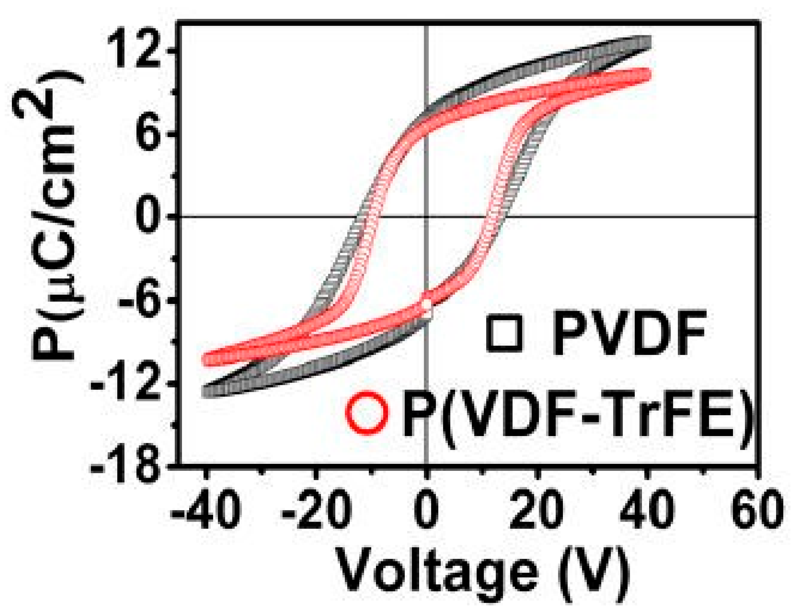
| Property | PVDF | P(VDF-TrFE) |
|---|---|---|
| Dielectric constant (1 kHz at 25 °C) | 12.5 | 13.2 |
| Dielectric loss | 0.031 | 0.023 |
| d33 (pC/N) | −15 | −17.8 |
| Breakdown Strength (MV/m) | 523 ± 25 | 402 ± 25 |
| Sample | d33 (pC/N) |
|---|---|
| P(VDF-TrFE) | 21 |
| P(VDF-TrFE)/ZnO (1) | 21 |
| P(VDF-TrFE)/ZnO (3) | 22 |
| P(VDF-TrFE)/ZnO (4) | 19 |
| Synthesis Method | Advantages | Disadvantages |
|---|---|---|
| Electrospinning method | 1. Preparation of ultra-thin films with uniformity 2. Piezoelectric behaviour of sample without poling and stretching 3. Preparation of sample with desired mechanical properties by the fine tuning of heat process 4. Higher β phase fibre preparation by adjusting electrospinning parameters. | 1. Requirement of high electric source 2. Use of halogenated and toxic organic solvents |
| Spin-coating method | 1. Fast and easy to operate 2. Preparation of thin films 3. High reproducibility 4. Uniformity of films | 1. Porosity and agglomeration 2. Crystallization depends on substrate temperature 3. Poling of film is generally required for higher piezoelectric nature. 4. Annealing is required for β Phase. |
| Solution casting | 1. Normally dissolution undergoes at room temperature 2. Fabrication of complex shapes 3. Dimensional stability 4. Lower cost and minimal setup time | 1. Application of high temperature and electric filed for production of β Phase 2. Poling is generally required for higher piezoelectric nature 3. Sometimes high temperature is required to improve dissolution. |
| Melt Extrusion | 1. Solvent-free method 2. Uniformity | 1. Degradation of polymer due to high stress. 2. Polymers with high temperature resistance is required. |
| LB technique | 1. Preparation of ultra-thin films 2. Deposition of single or multi-layer 3. Film has high tunability and polarization switching | 1. Complicated and time consuming 2. High hydrophobicity 3. Low efficiency in reproducibility |
| PVDF Concentration (%) | Roughness (nm) | Ε | Remnant Polarization (mC/cm2) |
|---|---|---|---|
| 0 | 5.93 | 8.6 | 8.4 |
| 20 | 5.36 | 9 | 5.5 |
| 40 | 4.11 | 9.4 | 4.3 |
| 80 | 6.70 | 10.2 | 0.2 |
| Sr No | Sample Prepared | Method of Preparation | Dielectric Out come | Ferroelectric Outcome | Piezoelectric Outcome | Electrical Outcome | Reference |
|---|---|---|---|---|---|---|---|
| 1 | Fe(0.05) doped ZnO/P(VDF-TrFE) | Solvent casting | 21.03 at 1 kHZ | Pr: 0.125 μC/cm2 | - | Output voltage ~ 7 V | R Sahoo et al. [143] |
| 2 | Ca doped ZnO/P(VDF-TrFE | Solvent casting | 15.3 | Pr: 0.125 μC/cm2 Ec 41 MV/m | - | Output voltage 3 V | R Sahoo et al. [144] |
| 3 | CO/P(VDF-TrFe)/PDMS/Nylon/Ag | Electro Spinning | - | - | d33: −20 pmV−1 | 3.9 V (10 pieces of C-PEG) 9.5 V (20 pieces of C-PEG) | J H Kim et al. [145] |
| 4 | P(VDF-TrFE) | Solution casting | 12 (VDF:TrFE-71:29) 11 (VDF:TrFE-72.2:27.8) | Pr: 5.7 μC/cm2 Ec 56.8 MV/m(VDF:TrFE-71:29) Pr: 6.5 μC/cm2 Ec 54.7 MV/m(VDF:TrFE-71:29) | d33: −58 p C/N (VDF:TrFE-72.2:27.8) | - | A Aliane et al. [146] |
| 5 | P(VDF-TrFE)/NiFe2O4 | Spin Coating | - | - | d33: 32 p C/N(NF 1 wt%) 26 p C/N(NF 0.5 wt%) | Output Voltage—1.4 V, Power density—0.05 Μw/cm3 | Sujoy Kumar et al. [147] |
| 6 | P(VDF-TrFE) | Solution Casting | 11.9 | Pr: 11.4 μC/cm2 | d33:25 p C/N | - | Q.Q Sun et al. [148] |
| 7 | P(VDF-TrFE)/FeCoSiB | Solution casting | - | - | d33: 34.87 p C/N | ME voltage-111 V/cm.Oe | Dandan Wen et al. [149] |
| 8 | P(VDF-TrFE)/BiFeO3-NaNbO3) | Spin Coating | PS: 8 μC/cm2 for 5% vol % of BiFeO3-NaNbO3 | d33: 34 p C/N for 5 vol % of BiFeO3-NaNbO3 d33: 38 p C/N for 10 vol % of BiFeO3-NaNbO3 | -- | R P Ummer et al. [150] | |
| 9 | P(VDF-TrFE)/Carbon Nanotubes | Solution Casting | - | - | d33 26.4 ± 1.3 pC/N | Voltage—2.7 V | Jia Wun Li et al. [151] |
| 10 | P(VDF-TrFE)/ Polysterene | Solution casting | 18.8 at 103 Hz for 10 wt% of CTAB modified PS. | - | - | Short circuit current density 47.45 mA, Peak power density: 7.88 W/m2 | Liqin Yao et al. [152] |
| 11 | P(VDF-TrFE) | Electro Spinning | - | - | d31 22.88 pC/N | Voltage 1.7 V Current 41.5 nA | Aochen Wang et al. [153] |
| 12 | P(VDF-TrFE) | Spin Coating | - | 2Pr: 5.55 μC/cm2 | - | Open circuit output Voltage—4.02 V | Yi Pei Jang et al. [154] |
| 13 | P(VDF-TrFE), PEDOT:PSS | Electro Spinning | - | - | d33eff ~ 31.5 pmV−1 (no core sample) d33eff ~ 58.3 pmV−1 (0.65:1) sample | Output voltage 8.76 V, Current 547 nA | Ju Han et al. [155] |
| 14 | P(VDF-TrFE)/Neodymium/Cobalt | Spin Coating | 30–40 | d33 26.4 ± 1.3 pC/N | Conductivity 3 × 10⁶–1 × 10⁹ | N Hernandez et al. [156] | |
| 15 | P(VDF-TrFE) | Spin Coating | - | Pr: 6.1 μC/cm2 Ec 74.9 V/μm | - | Output Power 35.1 pW, Power Output Density—97.5 pW/mm2 | Alperen Toprak et al. [157] |
| 16 | P(VDF-TrFE) | Spin Coating | - | Ec 55 V/μw | d33 23.9 pm/V | - | Alperen Toprak et al. [158] |
| 17 | P(VDF-TrFE) | Solution Casting | - | - | d33—28 Pc/N | Output Voltage 8.7 V | X Hu et al. [159] |
| 18 | P(VDF-TrFE) | Spin Coating | - | Pr: 5.6 μC/cm2 at −5 V Pr: 4.61 μC/cm2 at −60 V Ec 1000 kV/cm at −15 V | d33—10.7 pC/N at 0 V d33—5 pC/N at −60 V | - | H J Tseng et al. [56] |
| 19 | P(VDF-TrFE) | Solution casting | d33 10.7 pC/N | Output Voltage 8.7 V | G Ahn et al. [160] | ||
| 20 | P(VDF-TrFE) | Spin Casting | Pr: 4.7 µC/cm2 Ec 53 Vμm−1 | d33 −29.8 pmV−1 | D Dishan et al. [161] |
Disclaimer/Publisher’s Note: The statements, opinions and data contained in all publications are solely those of the individual author(s) and contributor(s) and not of MDPI and/or the editor(s). MDPI and/or the editor(s) disclaim responsibility for any injury to people or property resulting from any ideas, methods, instructions or products referred to in the content. |
© 2023 by the authors. Licensee MDPI, Basel, Switzerland. This article is an open access article distributed under the terms and conditions of the Creative Commons Attribution (CC BY) license (https://creativecommons.org/licenses/by/4.0/).
Share and Cite
P S, L.P.; Swain, B.; Rajput, S.; Behera, S.; Parida, S. Advances in P(VDF-TrFE) Composites: A Methodical Review on Enhanced Properties and Emerging Electronics Applications. Condens. Matter 2023, 8, 105. https://doi.org/10.3390/condmat8040105
P S LP, Swain B, Rajput S, Behera S, Parida S. Advances in P(VDF-TrFE) Composites: A Methodical Review on Enhanced Properties and Emerging Electronics Applications. Condensed Matter. 2023; 8(4):105. https://doi.org/10.3390/condmat8040105
Chicago/Turabian StyleP S, Lekshmi Priya, Biswaranjan Swain, Shailendra Rajput, Saubhagyalaxmi Behera, and Sabyasachi Parida. 2023. "Advances in P(VDF-TrFE) Composites: A Methodical Review on Enhanced Properties and Emerging Electronics Applications" Condensed Matter 8, no. 4: 105. https://doi.org/10.3390/condmat8040105