
Design, Modeling, and Control of a New Multi-Motion Mobile Robot Based on Spoked Mecanum Wheels

Abstract
:1. Introduction
- 1.
- A simple-structured flexible spoked mecanum wheel with excellent obstacle-crossing and omnidirectional movement capabilities is proposed. In addition, a mobile robot, LZ-1, based on this motion mechanism was designed and manufactured for experimentation.
- 2.
- An omnidirectional motion mode that can achieve omnidirectional movement and surpasses the obstacle-crossing performance of traditional mecanum wheel mobile robots and a crawl motion mode that can climb continuous stairs were developed for the LZ-1 robot.
- 3.
- Numerous experiments demonstrated that the omnidirectional motion mode and crawl motion mode developed for the LZ-1 robot are practical and can be used in future mobile operations on unstructured terrains.
2. Design, Modeling, and Control
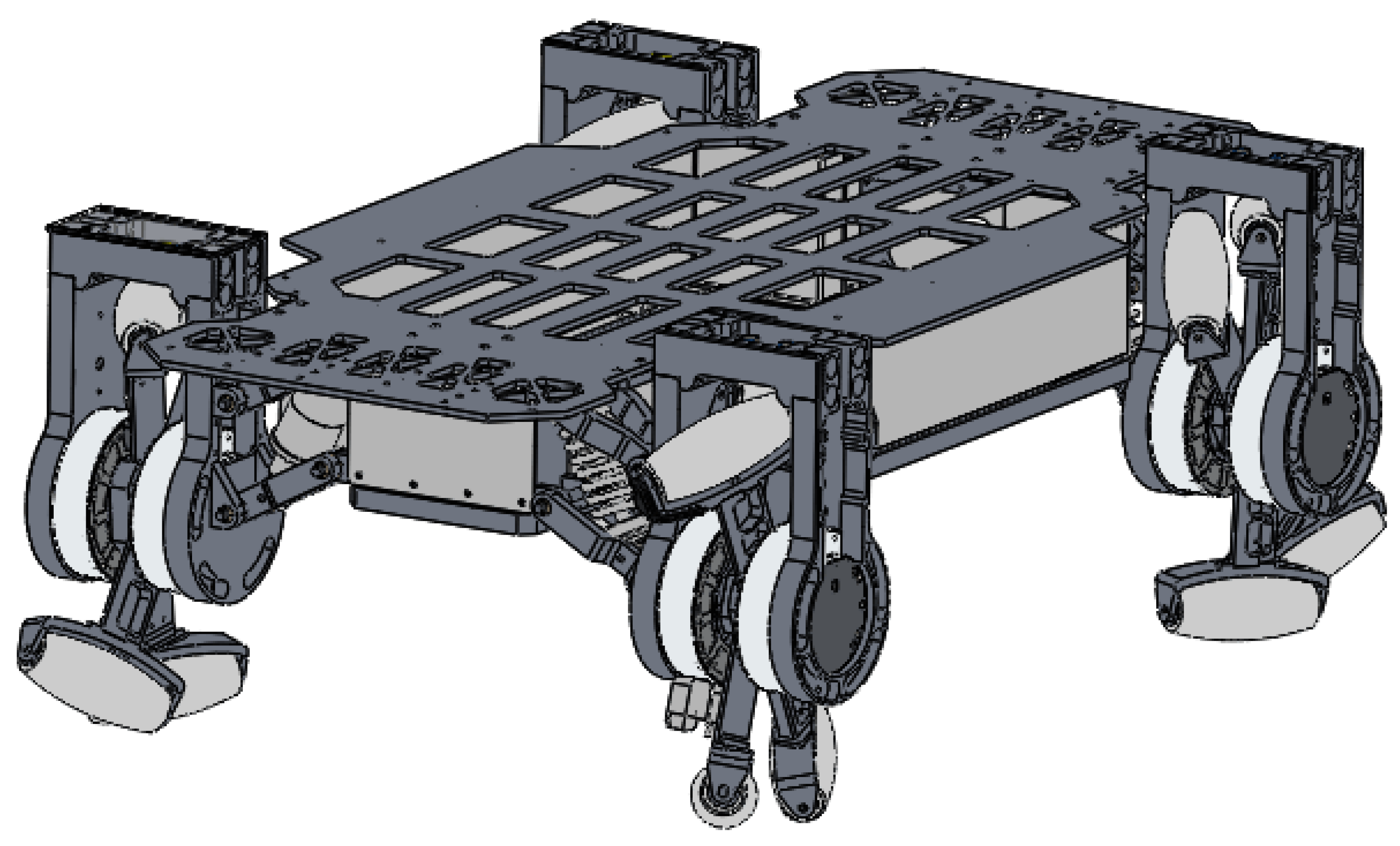
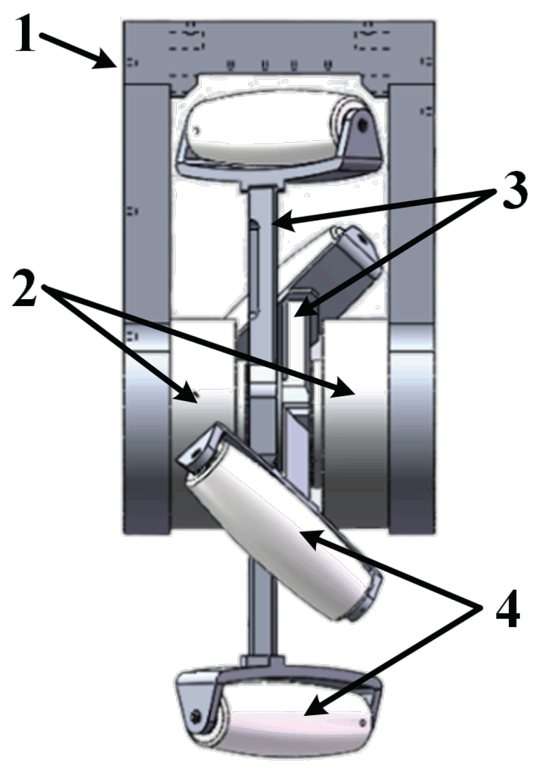
2.1. Robot Design
- 1.
- A U-shaped metal piece for fixing two spoke components and connecting the FSM wheel to the robot’s main body;
- 2.
- Two servo motors that drive the two spoke components separately. These servo motors are fixed on that U-shaped piece, and their rotation axes are collinear. Each servo motor has a built-in controller that allows us to easily set its speed or rotation position through a communication bus;
- 3.
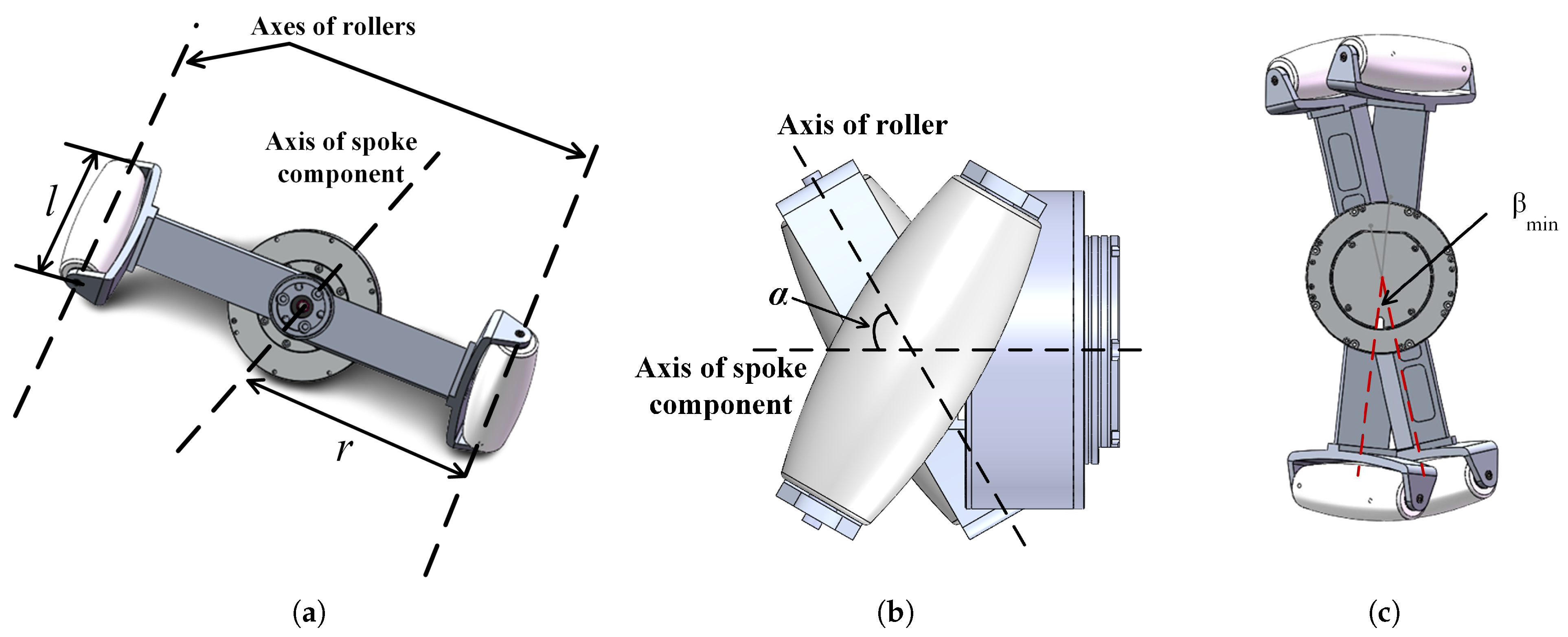
- Two spoke components with their centers fixed on the servo motor rotation axes;
- 4.
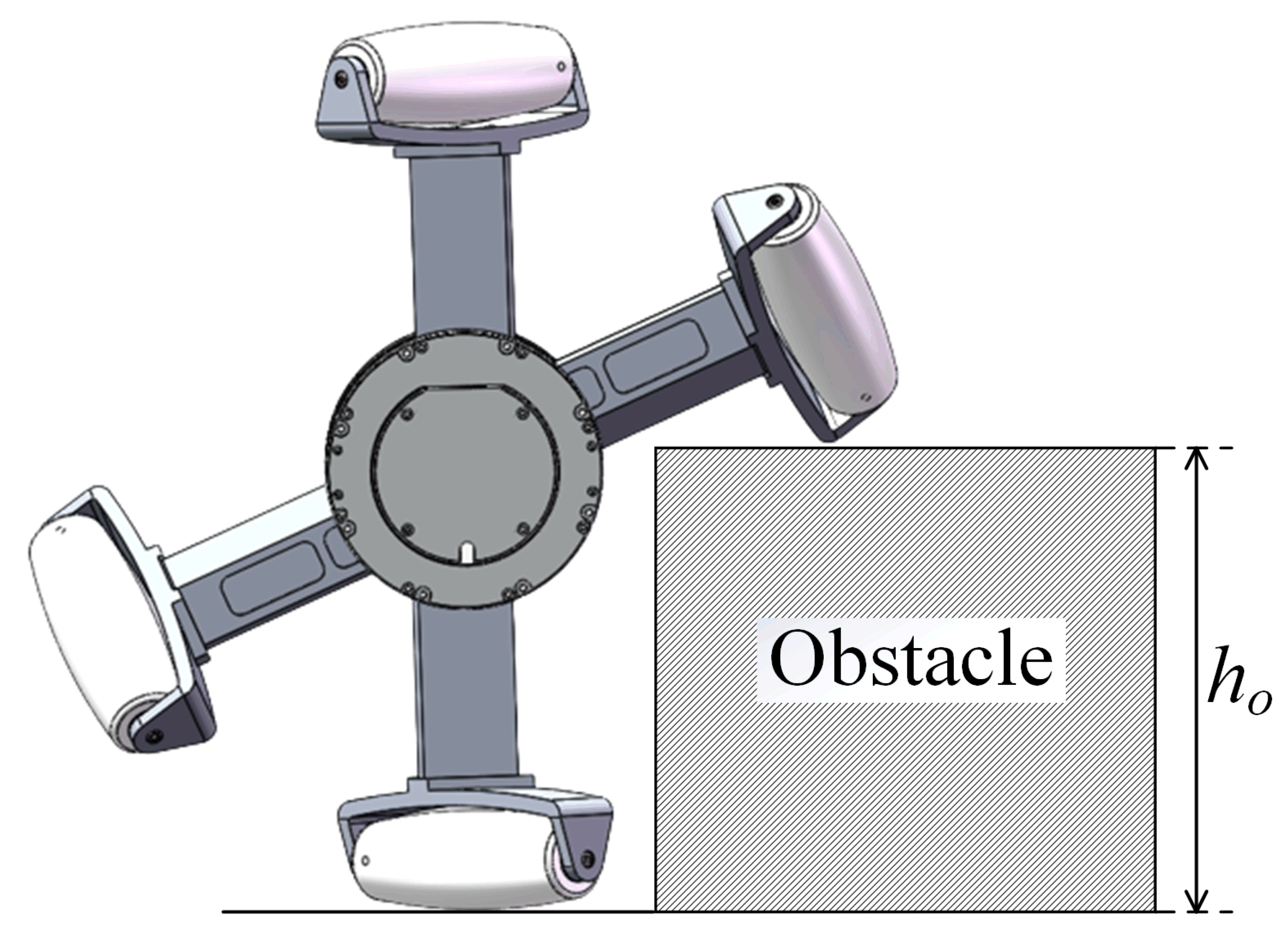
- Four rollers that can rotate freely under external force at each end of each spoke component.
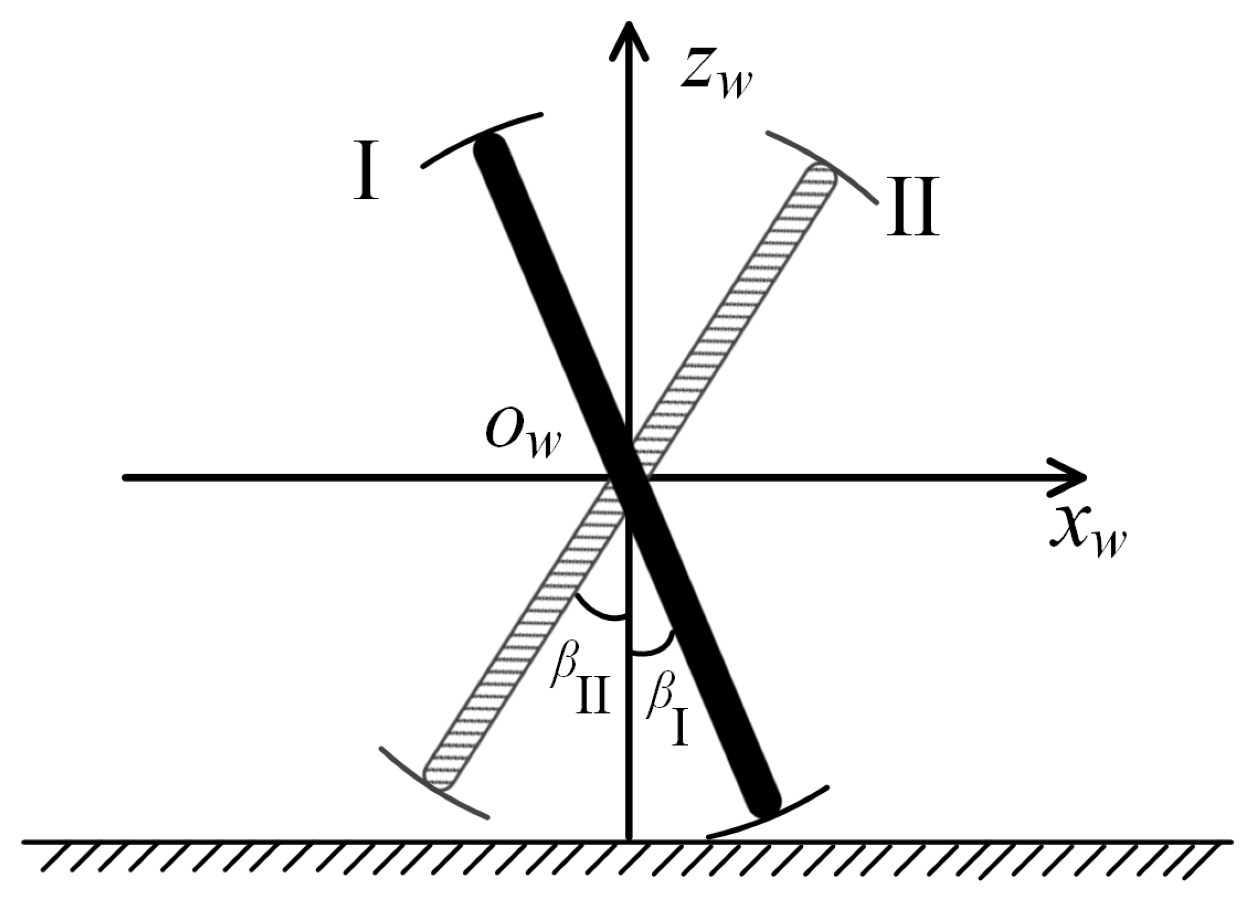
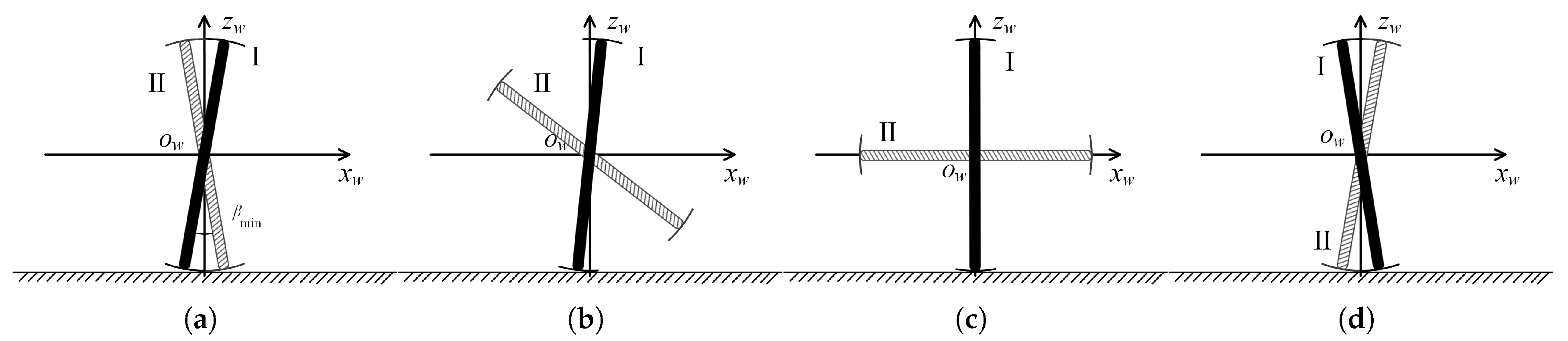
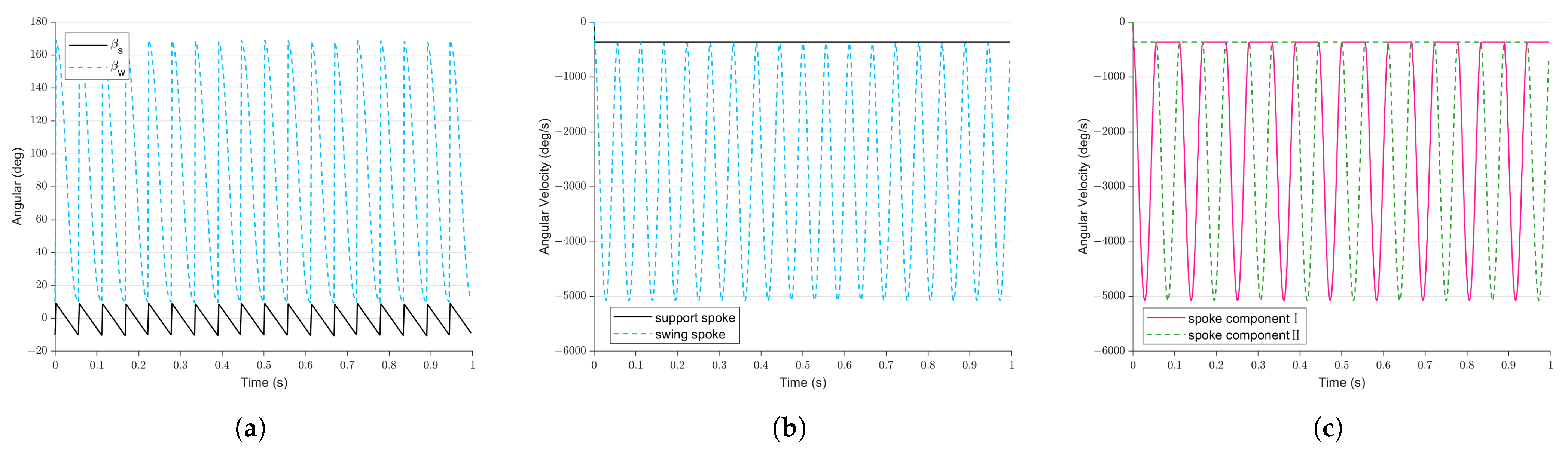
2.2. Locomotion Modeling
- 1.
- Omnidirectional motion mode: In this mode, the LZ-1 can achieve omnidirectional movement on flat ground, similar to a mecanum-wheeled mobile robot, while being able to cross some concave or convex obstacles.
- 2.
- Crawl motion mode: In this mode, the LZ-1 can climb standard walking stairs.
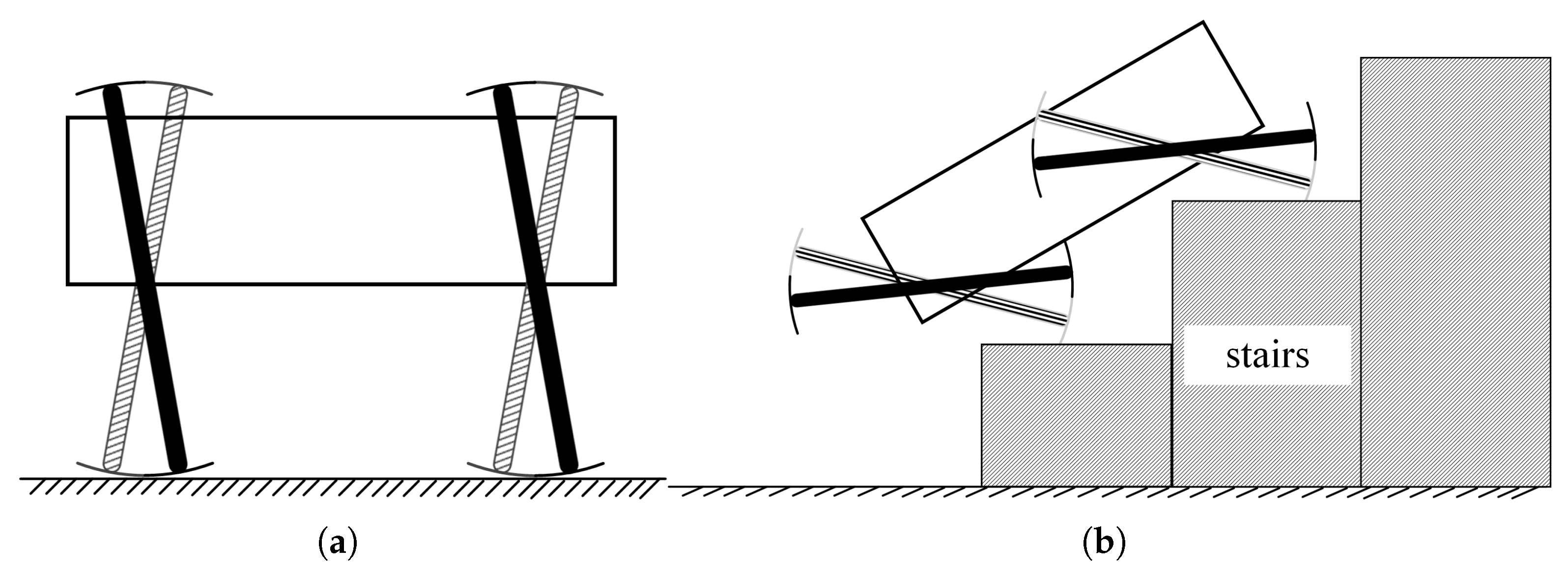
2.2.1. Omnidirectional Motion Mode
2.2.2. Crawl Motion Mode
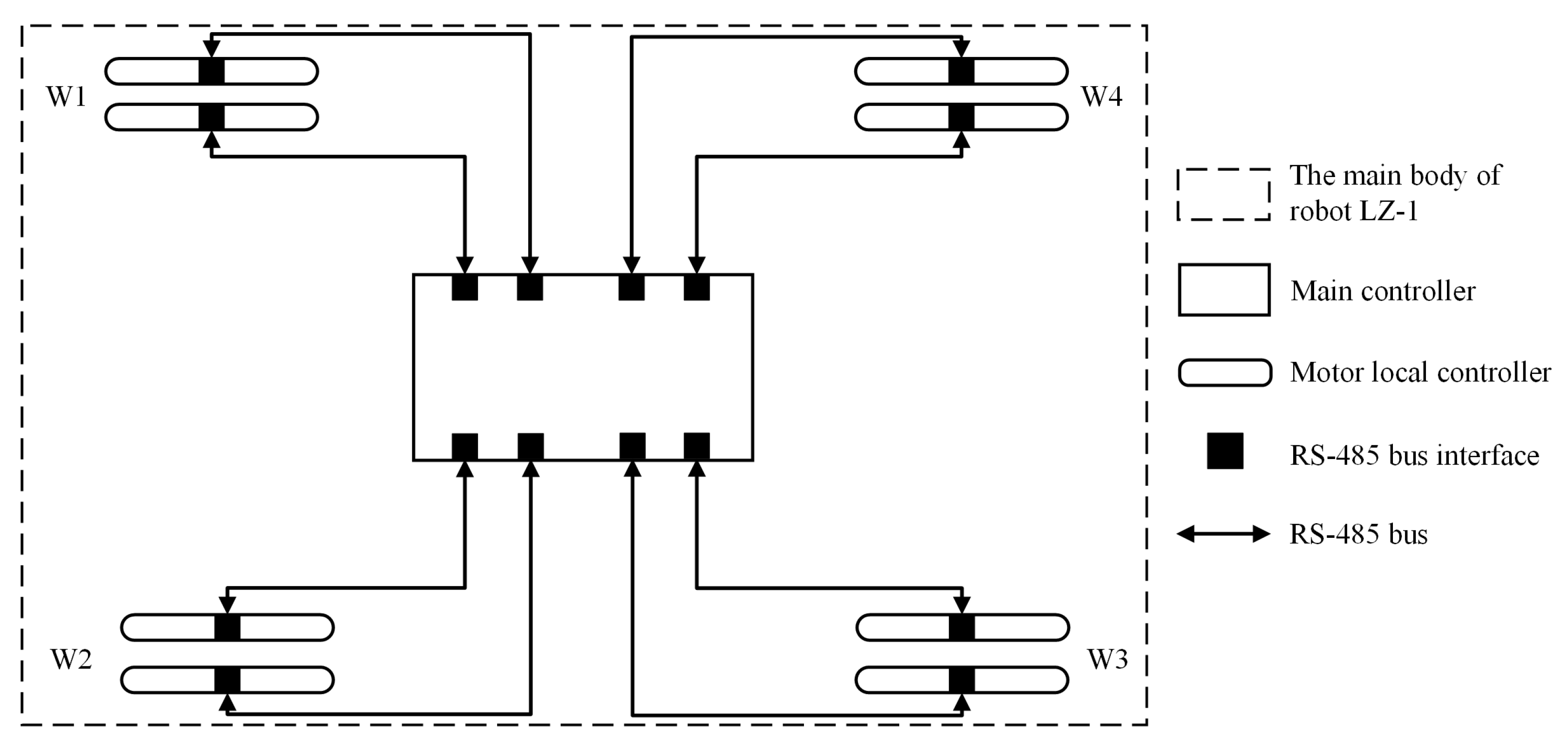
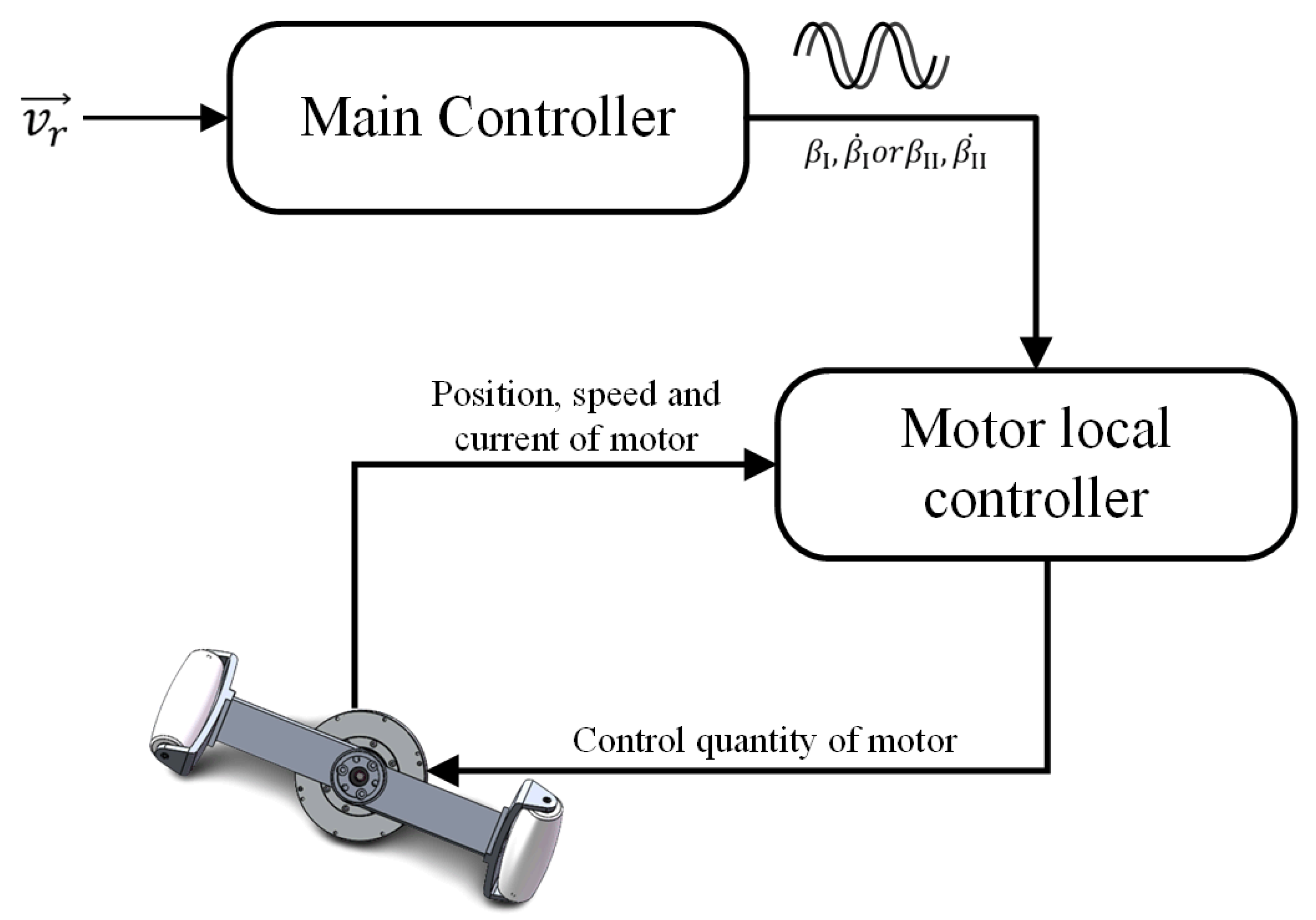
2.3. Control Method
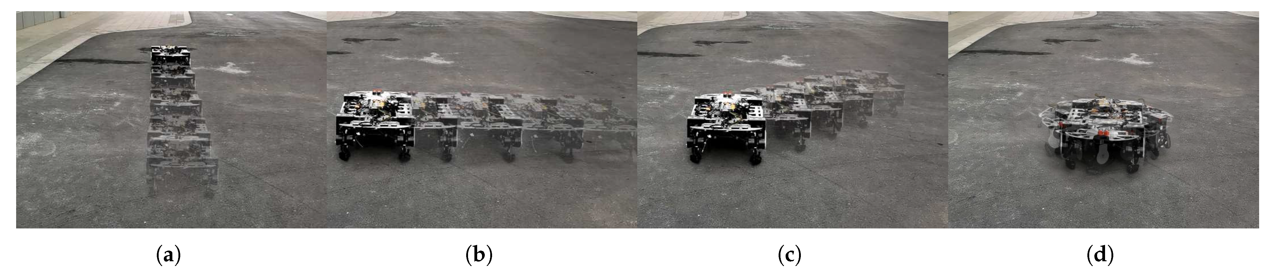
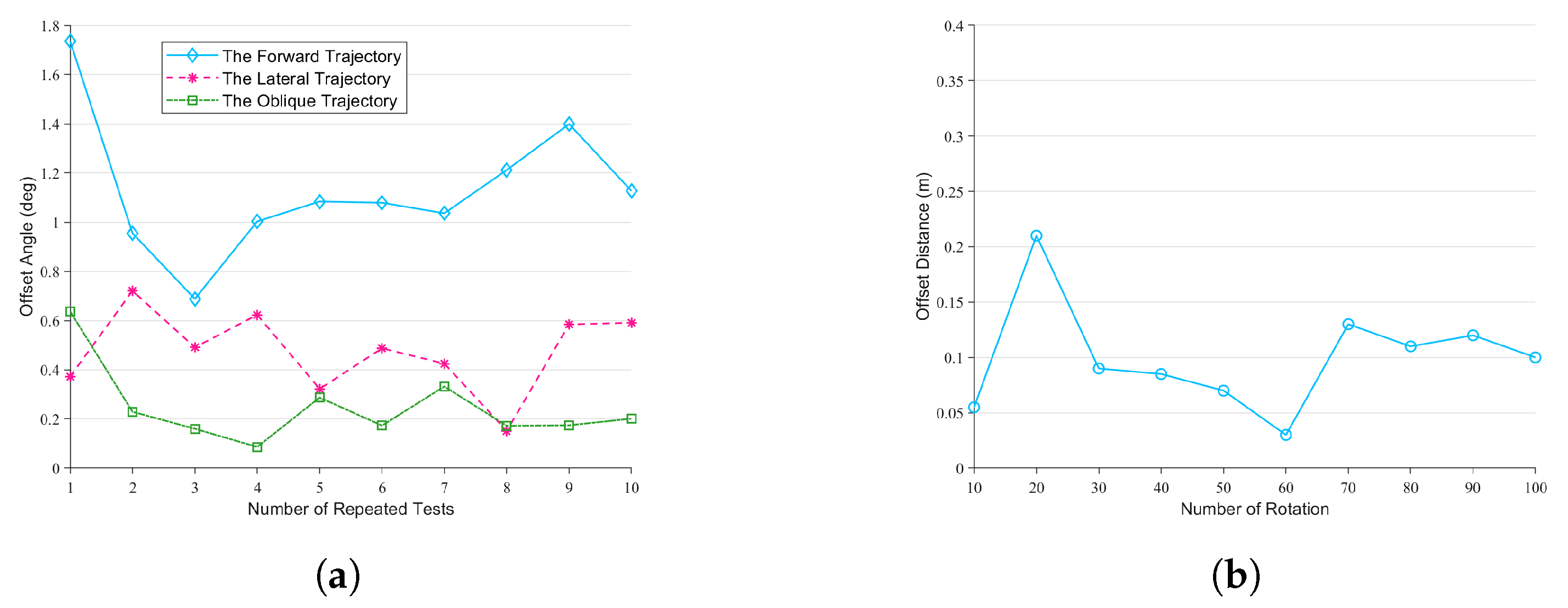
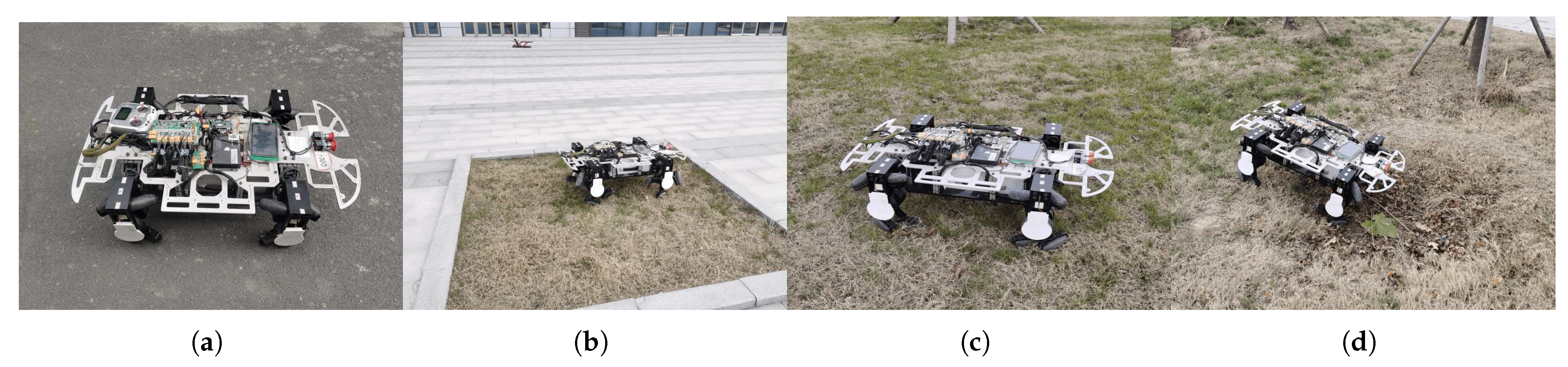
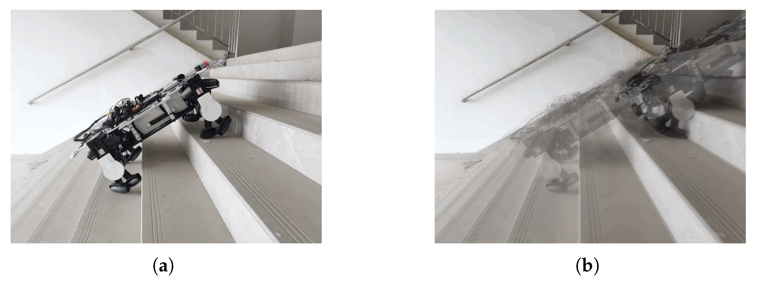
3. Experiments and Results
4. Discussion and Conclusions
- 1.
- The LZ-1 robot had omnidirectional mobility similar to traditional mecanum-wheeled mobile robots and a better obstacle-crossing ability. It can move on uneven terrain and climb continuous stairs.
- 2.
- Compared to the first type of hybrid mobile robot, the LZ-1 has a simpler structural design and uses fewer motors to move on various terrains. A typical wheel-legged hybrid robot requires about four motors for one leg, while our FSM-wheeled robot only needs two per leg.
- 3.
- Compared to the second type of hybrid mobile robot, the LZ-1 has a more straightforward process of changing motion modes. It can change between omnidirectional and crawl motion modes without changing the motion mechanism’s configuration.
- 4.
- The LZ-1 robot is a solution for mobile robots that balances design cost, control complexity, mobility, flexibility, and multi-terrain adaptability.
- 1.
- Improve the structural design and reduce possible errors;
- 2.
- Design more useful motion modes;
- 3.
- Study methods for switching between multiple motion modes;
- 4.
- Explore the impact of different loads on the robot’s movement capabilities;
- 5.
- Enable the LZ-1 to recognize terrain changes and switch motion modes autonomously.
Supplementary Materials
Author Contributions
Funding
Institutional Review Board Statement
Data Availability Statement
Conflicts of Interest
References
- Bledt, G.; Powell, M.J.; Katz, B.; Di Carlo, J.; Wensing, P.M.; Kim, S. MIT Cheetah 3: Design and Control of a Robust, Dynamic Quadruped Robot. In Proceedings of the 2018 IEEE/RSJ International Conference on Intelligent Robots and Systems (IROS), Madrid, Spain, 1–5 October 2018; pp. 2245–2252. [Google Scholar] [CrossRef]
- Reher, J.; Ma, W.L.; Ames, A.D. Dynamic Walking with Compliance on a Cassie Bipedal Robot. In Proceedings of the 2019 18th European Control Conference (ECC), Naples, Italy, 25–28 June 2019; pp. 2589–2595. [Google Scholar] [CrossRef]
- Zhao, J.; Han, T.; Wang, S.; Liu, C.; Fang, J.; Liu, S. Design and Research of All-Terrain Wheel-Legged Robot. Sensors 2021, 21, 5367. [Google Scholar] [CrossRef] [PubMed]
- Orozco-Magdaleno, E.C.; Gómez-Bravo, F.; Castillo-Castañeda, E.; Carbone, G. Evaluation of Locomotion Performances for a Mecanum-Wheeled Hybrid Hexapod Robot. IEEE/ASME Trans. Mechatron. 2021, 26, 1657–1667. [Google Scholar] [CrossRef]
- Chen, Z.; Li, J.; Wang, J.; Wang, S.; Zhao, J.; Li, J. Towards Hybrid Gait Obstacle Avoidance for a Six Wheel-Legged Robot with Payload Transportation. J. Intell. Robot. Syst. 2021, 102, 60. [Google Scholar] [CrossRef]
- Chen, Z.; Li, J.; Wang, S.; Wang, J.; Ma, L. Flexible gait transition for six wheel-legged robot with unstructured terrains. Robot. Auton. Syst. 2022, 150, 103989. [Google Scholar] [CrossRef]
- Wang, S.; Chen, Z.; Li, J.; Wang, J.; Li, J.; Zhao, J. Flexible Motion Framework of the Six Wheel-Legged Robot: Experimental Results. IEEE/ASME Trans. Mechatron. 2022, 27, 2246–2257. [Google Scholar] [CrossRef]
- Altendorfer, R.; Moore, N.; Komsuoglu, H.; Buehler, M.; Brown, H.; McMordie, D.; Saranli, U.; Full, R.; Koditschek, D. RHex: A Biologically Inspired Hexapod Runner. Auton. Robot. 2001, 11, 207–213. [Google Scholar] [CrossRef]
- Fremerey, M.; Djordjevic, G.S.; Witte, H. WARMOR: Whegs Adaptation and Reconfiguration of MOdular Robot with Tunable Compliance. In Proceedings of the Biomimetic and Biohybrid Systems, Living Machines 2012, Barcelona, Spain, 9–12 July 2012; Prescott, T.J., Lepora, N.F., Mura, A., Verschure, P.F.M.J., Eds.; Springer: Berlin/Heidelberg, Germany, 2012; pp. 345–346. [Google Scholar] [CrossRef]
- Yang, M.; Kang, R.; Chen, Y. A Highly Mobile Crawling Robot Inspired by Hexapod Insects. In Proceedings of the 2019 IEEE International Conference on Robotics and Biomimetics (ROBIO), Dali, China, 6–8 December 2019; pp. 1797–1802. [Google Scholar] [CrossRef]
- Tao, Y.; Gao, C.; Shi, Y.; Li, M.; Zhang, M.; Liu, D. Analysis of Motion Characteristics and Stability of Mobile Robot Based on a Transformable Wheel Mechanism. Appl. Sci. 2022, 12, 12348. [Google Scholar] [CrossRef]
- Cao, R.; Gu, J.; Yu, C.; Rosendo, A. OmniWheg: An Omnidirectional Wheel-Leg Transformable Robot. In Proceedings of the 2022 IEEE/RSJ International Conference on Intelligent Robots and Systems (IROS), Kyoto, Japan, 23–27 October 2022; pp. 5626–5631. [Google Scholar] [CrossRef]
- Dai, C.; Liu, X.; Zhou, J.; Liu, Z.; Zhu, Z.; Jia, Z. SWhegPro: A Novel Robust Wheel-Leg Transformable Robot. In Proceedings of the 2022 IEEE International Conference on Robotics and Biomimetics (ROBIO), Xishuangbanna, China, 5–9 December 2022; pp. 421–426. [Google Scholar] [CrossRef]
- Fremerey, M.; Köhring, S.; Nassar, O.; Schöne, M.; Weinmeister, K.; Becker, F.; Đorđević, G.S.; Witte, H. A Phase-Shifting Double-Wheg-Module for Realization of Wheg-Driven Robots. In Proceedings of the Biomimetic and Biohybrid Systems, Living Machines 2014, Milan, Italy, 30 July–1 August 2014; Duff, A., Lepora, N.F., Mura, A., Prescott, T.J., Verschure, P.F.M.J., Eds.; Springer: Cham, Switzerland, 2014; pp. 97–107. [Google Scholar] [CrossRef]
- Tlale, N.; de Villiers, M. Kinematics and Dynamics Modelling of a Mecanum Wheeled Mobile Platform. In Proceedings of the 2008 15th International Conference on Mechatronics and Machine Vision in Practice, Auckland, New Zealand, 2–4 December 2008; pp. 657–662. [Google Scholar] [CrossRef]
- Mutalib, M.A.A.; Azlan, N.Z. Prototype development of mecanum wheels mobile robot: A review. Appl. Res. Smart Technol. (ARSTech) 2020, 1, 71–82. [Google Scholar] [CrossRef]
- Wampfler, G.; Salecker, M.; Wittenburg, J. Kinematics, Dynamics, and Control of Omnidirectional Vehicles with Mecanum Wheels. Mech. Struct. Mach. 1989, 17, 165–177. [Google Scholar] [CrossRef]
- Xie, L.; Herberger, W.; Xu, W.; Stol, K.A. Experimental validation of energy consumption model for the four-wheeled omnidirectional Mecanum robots for energy-optimal motion control. In Proceedings of the 2016 IEEE 14th International Workshop on Advanced Motion Control (AMC), Auckland, New Zealand, 22–24 April 2016; pp. 565–572. [Google Scholar] [CrossRef]
- Iversen, S.; Jouffroy, J. Umbrella wheel—A stair-climbing and obstacle-handling wheel design concept. In Proceedings of the 2017 International Conference on Advanced Mechatronic Systems (ICAMechS), Xiamen, China, 6–9 December 2017; pp. 312–317. [Google Scholar] [CrossRef]


| Parameter Names | Symbols | Values | Unit |
|---|---|---|---|
| Half the length of the spoke component | r | 0.160 | m |
| Length of the roller | l | 0.101 | m |
| Diameter of the roller | d | 0.036 | m |
| Angle between the roller and the FSM wheel axes | α | −60 or 60 | deg |
| Minimum included angle between the two spoke components | βmin | 20 | deg |
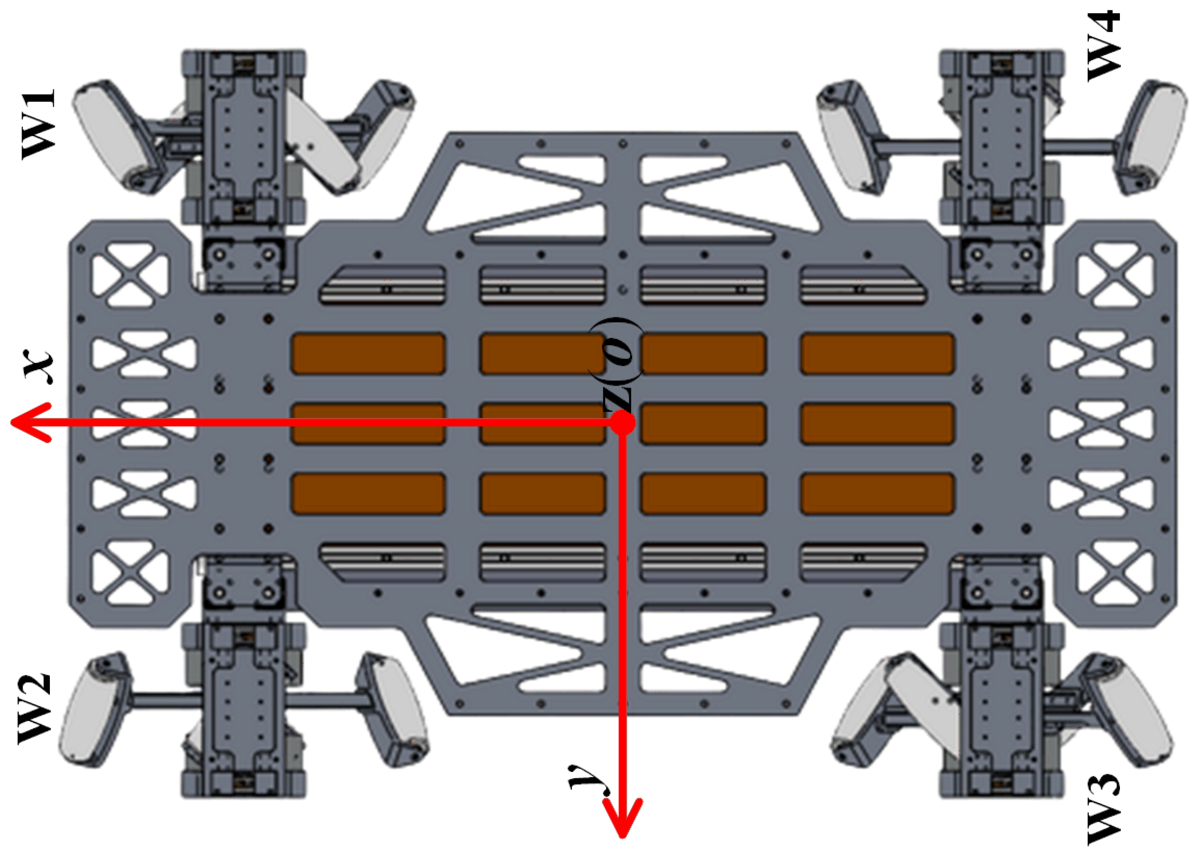
| Parameter Names | Symbols | Values | Unit |
|---|---|---|---|
| The length of LZ-1 | L | 0.950 | m |
| The width of LZ-1 | K | 0.640 | m |
| The height of LZ-1 | H | 0.335 | m |
| The weight of LZ-1 | M | 47 | kg |
| The front and rear FSM wheels’ distance | F | 0.630 | m |
| The left and right FSM wheels’ distance | B | 0.489 | m |
Disclaimer/Publisher’s Note: The statements, opinions and data contained in all publications are solely those of the individual author(s) and contributor(s) and not of MDPI and/or the editor(s). MDPI and/or the editor(s) disclaim responsibility for any injury to people or property resulting from any ideas, methods, instructions or products referred to in the content. |
© 2023 by the authors. Licensee MDPI, Basel, Switzerland. This article is an open access article distributed under the terms and conditions of the Creative Commons Attribution (CC BY) license (https://creativecommons.org/licenses/by/4.0/).
Share and Cite
Leng, J.; Mou, H.; Tang, J.; Li, Q.; Zhang, J. Design, Modeling, and Control of a New Multi-Motion Mobile Robot Based on Spoked Mecanum Wheels. Biomimetics 2023, 8, 183. https://doi.org/10.3390/biomimetics8020183
Leng J, Mou H, Tang J, Li Q, Zhang J. Design, Modeling, and Control of a New Multi-Motion Mobile Robot Based on Spoked Mecanum Wheels. Biomimetics. 2023; 8(2):183. https://doi.org/10.3390/biomimetics8020183
Chicago/Turabian StyleLeng, Jie, Haiming Mou, Jun Tang, Qingdu Li, and Jianwei Zhang. 2023. "Design, Modeling, and Control of a New Multi-Motion Mobile Robot Based on Spoked Mecanum Wheels" Biomimetics 8, no. 2: 183. https://doi.org/10.3390/biomimetics8020183