
Key Considerations in Assessing the Safety and Performance of Camera-Based Mirror Systems

 , , , and
Abstract
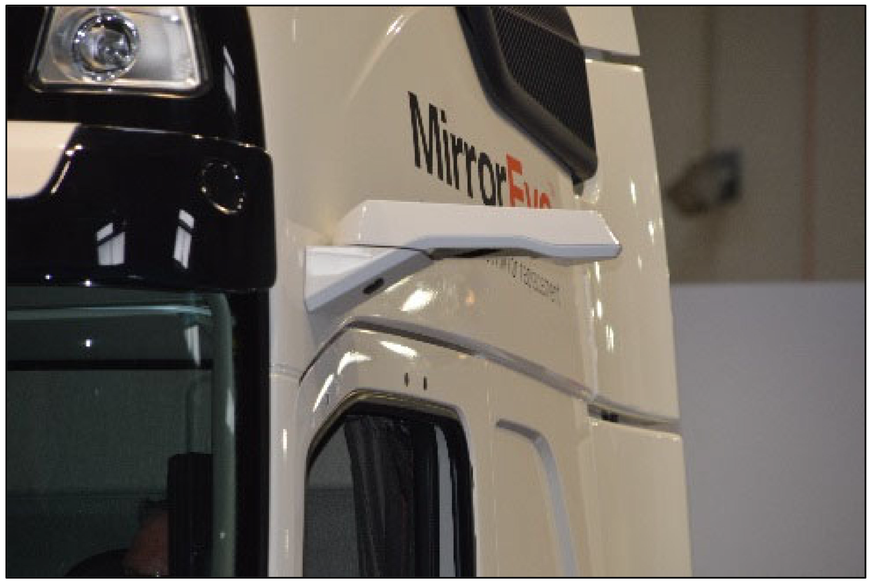
:1. Introduction to Camera-Based Mirror Systems
2. Development of Research Questions from Surveys and FMEA
2.1. Overview of Initial Driver Responses from Surveys
- Camera-based rear visibility system displays will make driving unsafe compared with traditional mirrors.
- Drivers will not be able to easily acclimate to using the visual displays of camera-based rear visibility systems and different display locations (if applicable).
- Camera-based rear visibility systems and related new technology will further remove the human from the driving task.
- Drivers doubt the camera-based rear visibility systems’ ability to function reliably and that cameras requiring power can fail unexpectedly and cause a lack of awareness of the drivers’ surroundings.
- Drivers suspect that law enforcement would have greater difficulty determining whether camera-based rear visibility systems are working correctly compared with traditional mirrors, for which damage can be easily determined.
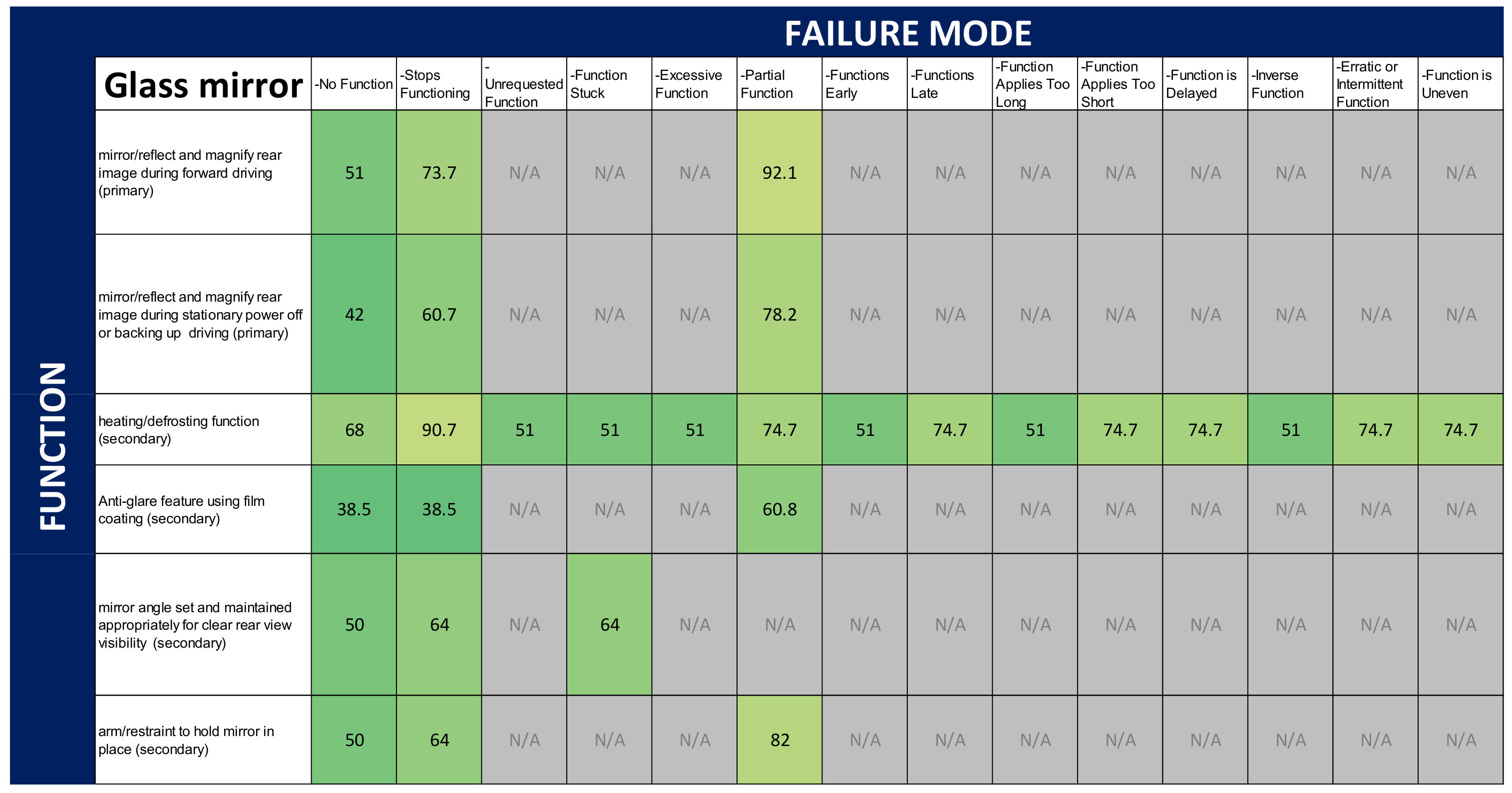
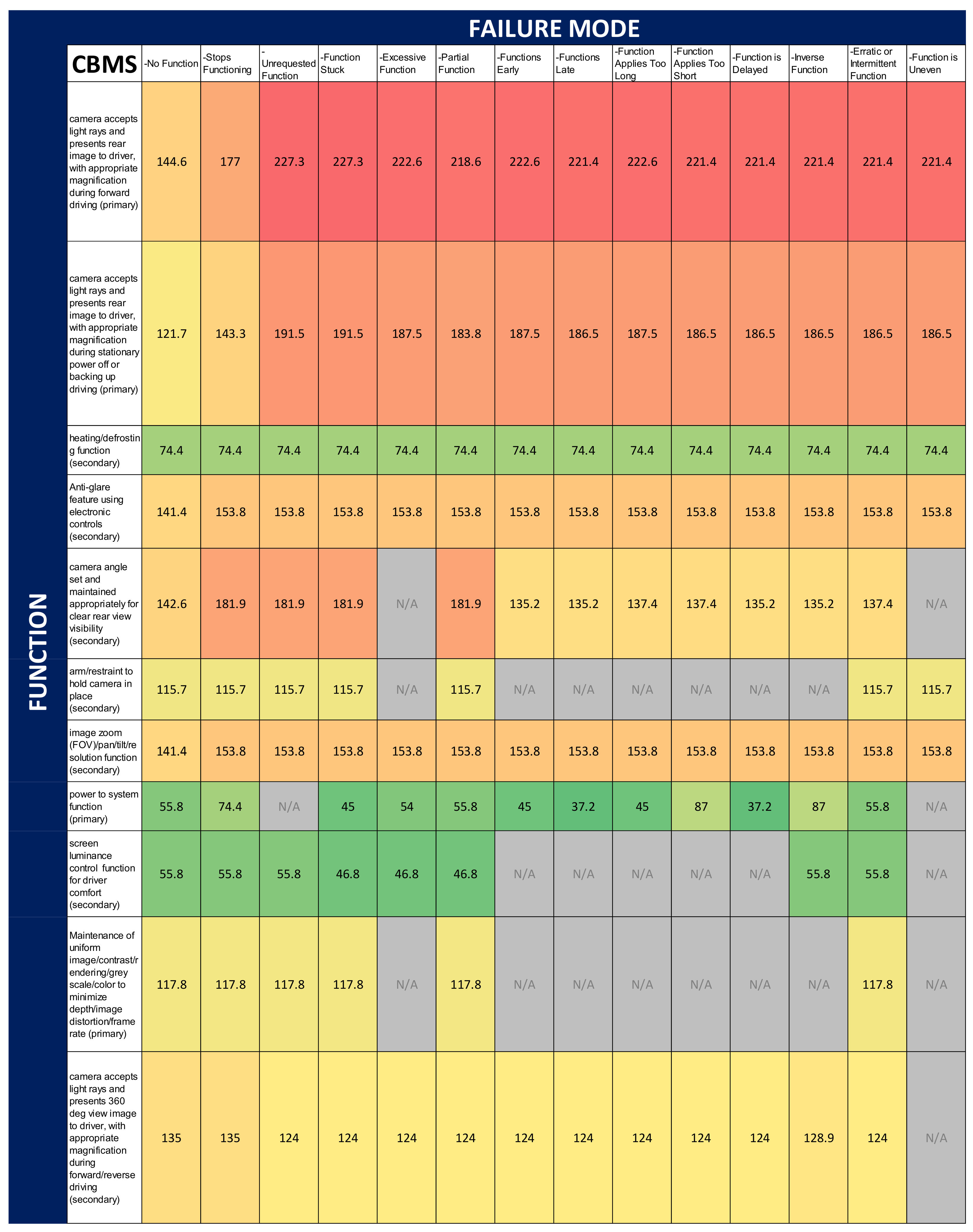
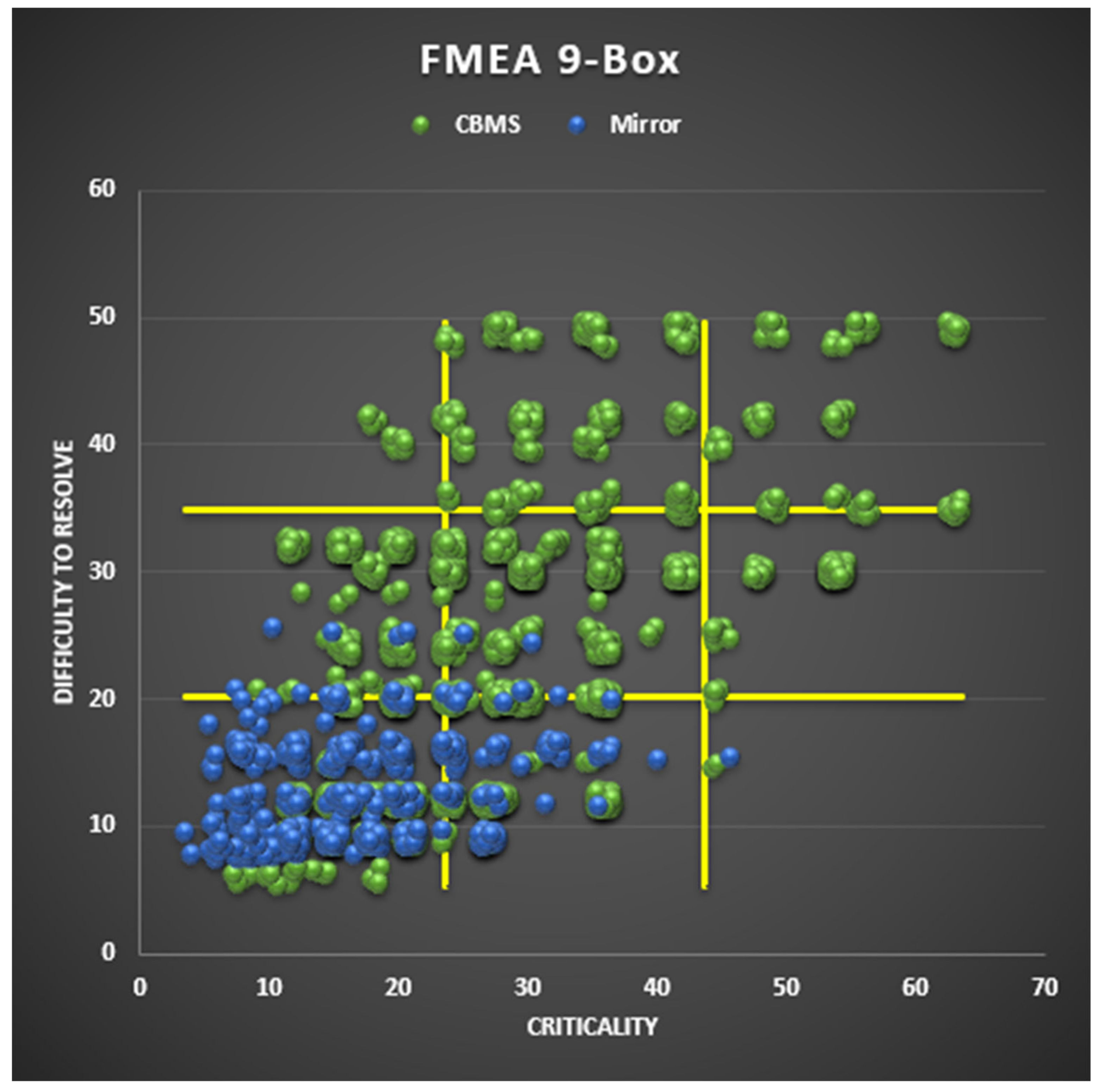
2.2. Failure Mode and Effects Analysis
2.3. Initial Considerations and Research Questions
3. Standards
3.1. Relevant Standards for Conventional Mirror Systems
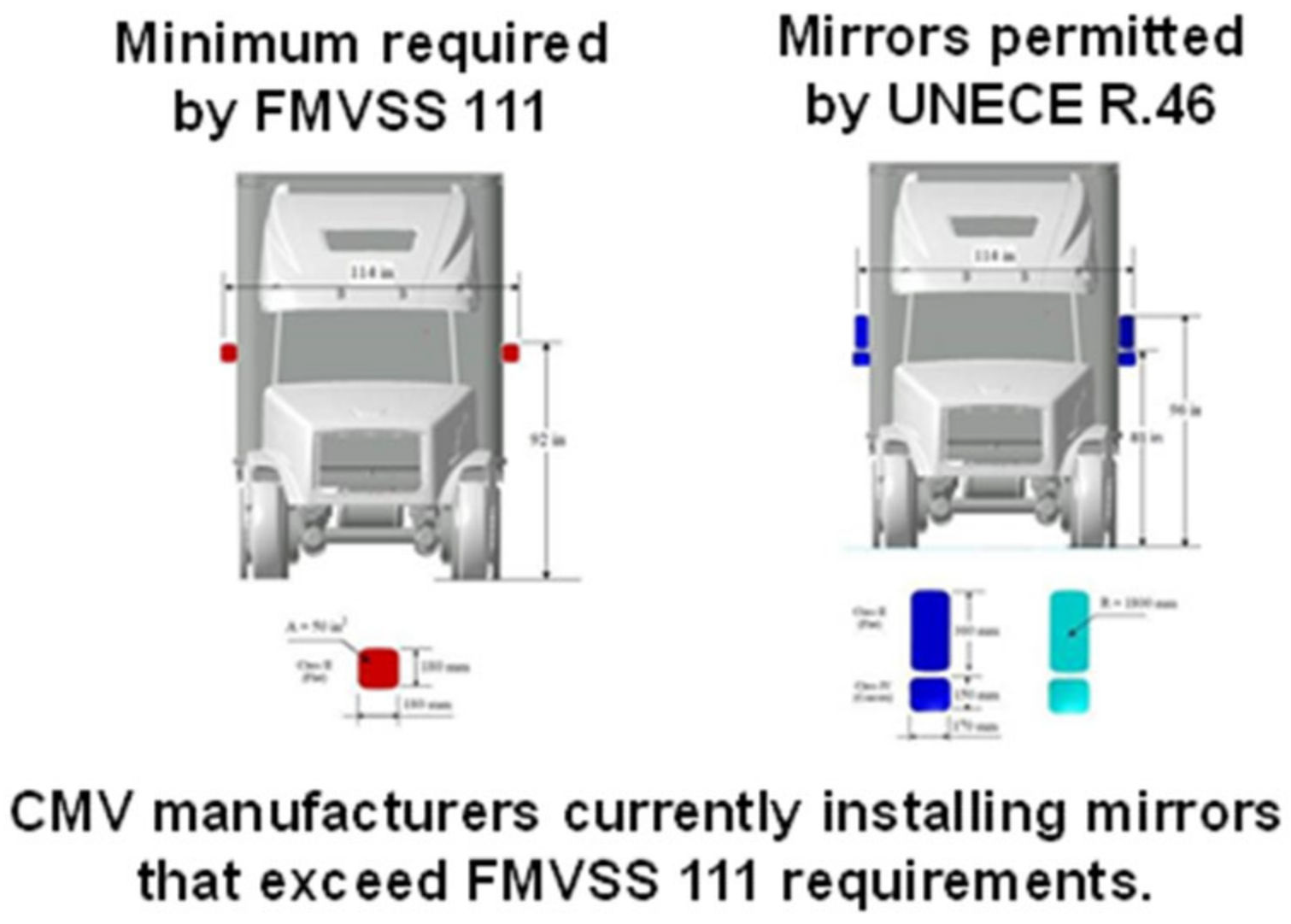
- Federal Motor Vehicle Safety Standard (FMVSS) No. 111: “Rearview mirrors” [9]: This standard specifies the requirements for rear visibility devices and systems, including their performance and location. In particular, the standard defines the required field of view and mounting for inside and outside rearview mirrors. The specifications apply to passenger cars, multipurpose passenger vehicles, trucks, buses, school buses, and motorcycles. This standard is crucial in testing because it provides the requirements for field of view needed.
- ISO 5740: Road vehicles—Rear view mirrors—Test method for determining reflectance [10]: This standard specifies a test method for determining the reflectance of rearview mirrors (i.e., the ratio of the luminous flux reflected by the mirror to the luminous flux that the mirror receives as input). It applies to flat mirrors and to mirrors that have convex surfaces for external or internal mounting. This standard is important in judging the mirrors’ ability to provide an image to the user but also to project glare.
3.2. Relevant Standards for Camera-Based Mirror Systems
- ISO 16505: Road vehicles—Ergonomic and performance aspects of Camera Monitor Systems—Requirements and test procedures [11]: This standard summarizes the minimum safety, ergonomics, and technical requirements to replace mandatory mirrors with CBMSs (referred to as camera monitor systems [CMS] in the standard). It specifically refers to classes I to IV as defined in the United Nations’ (UN) Regulation No. 46. The specifications are provided using a system-level approach that is applicable to any technology for the camera, display, and processing devices. The standard also includes test procedures related to operational readiness, field of view, magnification, object size and resolution of the CMS, monitor integration inside the vehicle, failure behavior, and influences from the weather and environment, among others. The outlined requirements are based on the properties of the mirror system to be replaced and aspects such as the visual acuity of the human operator. Some relevant definitions provided in the standard include the following: driver’s ocular points, ocular reference point, mirror distance to driver’s ocular reference point including maximum and minimum values, mirror viewing angle, angle of curvature, field of view for the mirror and camera, magnification factor, visual acuity of the human eye, camera resolution, monitor coordinate system, monitor viewing distance, monitor designed size, and CMS magnification factor. One key assumption in this standard is that the CMS can generate an ideal mapping of the real-world environment.
- ISO 9241: Ergonomics of human–system interaction [12]:
- (a)
- Part 302: “Terminology for electronic visual displays”: This part of the standard includes a list of definitions related to electronic visual displays and those used in other sections of ISO 9241. Some of the relevant definitions included in this standard are image formation time, monitor coordinate system, and luminance contrast.
- (b)
- Part 305: “Optical laboratory test methods for electronic visual displays”: This part of the standard defines methods for optical tests and observations used to predict the display’s performance considering the ergonomic aspects included in part 303.
- (c)
- Part 307: “Analysis and compliance test methods for electronic visual displays”: This part of the standard focuses on how hardware and software can improve the human–machine interface. It includes an overview of requirements to ensure that design principles for computer-based interactive systems are human centered. The details included allow planners and project managers to understand the relevance of involving technical human factors and ergonomics in the design process. The standard also establishes test methods to analyze visual display technologies, tasks, and environments independently of the technology. Definitions for reality in testing and visual artifacts are also included. The human factors, ergonomics, and accessibility aspects are treated in more detail in other standards (ISO 6385 and some parts of ISO 7241).
- ISO 15008: Road vehicles—ergonomic aspects of transport information and control systems—specifications and test procedures for in-vehicle visual presentation [13]: This standard focuses on the on-board transport information and control systems that are used while the vehicle is on a driving mission. In particular, it defines the requirements for image quality and legibility of displays that show dynamic visual information to the driver independently of the technology. It also includes methods and measurements to assess compliance. This standard is relevant for monitor integration and defines the meaning of luminance, contrast rendering, and image quality measurement.
- ISO 4513: Road vehicles—Visibility—Method for establishment of eyellipses for driver’s eye location [14]: This document establishes procedures to determine the location of the eyes of the driver inside a vehicle using elliptical 3D models. The definition of neck pivot points is given to define left and right eye points for viewing tasks such as those included in SAE J1050. This standard applies to class A and B vehicles.
- ISO 26262: Road vehicles—Functional safety—Part 1: Vocabulary [15]: This standard is applicable to safety-related systems that use one or more electrical/electronic (E/E) systems if they are part of road vehicles. Mopeds are excluded. It is focused on potential hazards due to malfunctioning behavior of E/E systems related to safety functions in vehicles. The following hazards are excluded unless they are directly related to malfunctioning behavior of the E/E systems: electric shock, fire, smoke, heat, radiation, toxicity, flammability, reactivity, corrosion, and release of energy. To help with the integration of functional safety activities in the developmental framework of a company, the document describes a complete framework for functional safety. The requirements included in the standard focus on (1) technical aspects of the functional safety implementation of a product or (2) the developmental process to demonstrate the functional safety capabilities of the organization.
- ISO 12233: Photography—electronic still picture imaging—resolution and spatial frequency responses [16]: This standard defines methods to measure the resolutions and spatial frequency responses of electronic still-picture cameras. It applies to monochrome and color cameras that produce digital data or analogue video signals.
- ISO 5385: Road vehicles—Anti-fog coating for exterior lighting devices—Specification [17]: The methods and requirements for anti-fog coatings of the exterior lighting devices of road vehicles are specified in this standard. It defines an anti-fog coating as a coating that can prevent all fogging on the exterior of a lens that has been made of glass, polycarbonate, polymethyl methacrylate, or other materials. An exterior lightning device is located outside of a vehicle and performs an illuminating or signaling function.
- ISO 2813: Paints and Varnishes- Determination of gloss value at 20°, 60° and 85° [18]: This standard applies to the monitor housing’s gloss and describes a method to determine the gloss value of coatings that is applicable to the measurement of gloss in nontextured coatings for plane and opaque substrates.
- UN Regulation No. 46: Uniform provisions concerning the approval of devices for indirect vision and of motor vehicles with regard to the installation of these devices [19]: This regulation applies to devices for indirect vision and their installation on category M and N motor vehicles and on motor vehicles with less than four wheels that enclose, partially or wholly, the driver. It lists relevant definitions such as devices for indirect vision, mirror, surveillance mirror, principal radii of curvature at one point on the reflecting surface, spherical surface, aspherical surface, and aspherical mirror, among others. It also outlines the steps that need to be followed to apply for the approval of devices for indirect vision including required information. Requirements and general specifications for mirrors and camera monitor devices for indirect vision are included along with the test procedures that should be performed. This regulation introduces some modifications to parameters defined in ISO 16505.
4. Previous Testing Found in the Literature
- Gaps in group 1—perceptions of safety: unit magnification in helping judge gap distances, anti-glare efficacy, and secured restraint of the mirror/camera system. These issues pertain to secondary functions of the CBMS. Testing scenarios both on road and in a simulation will help answer these questions.
- Gaps in group 2—response latency: image blooming, display aberrations, and mirror function while the system is powered off. The first two of these issues are secondary functions, whereas the third is a primary function of the system.
- Gaps in groups 3 and 4—health and fatigue issues and overstimulation: effects of glare and illumination of the screen on vision, and fatigue caused by a 360° view. These issues can be addressed in testing with eye tracking and facial expression analysis systems.
- Gaps in group 5—failure recovery: maintenance of the rear view, safe exiting, heating/defrosting, and merging during malfunctions. These issues will likely need to be addressed in future on-road testing.
- Gaps in group 6—lighting: delays in anti-glare due to tunnels or headlights, effects of the sun angle on image processing, and image distortion from reflection off bodies of water or strobing lights. These issues will require both lab and on-road testing scenarios to judge the effectiveness of these features.
5. Conclusions and Future Work
Author Contributions
Funding
Institutional Review Board Statement
Informed Consent Statement
Data Availability Statement
Conflicts of Interest
References
- Mazankova, M.J. Risks from blind spots of trucks. In Proceedings of the International Conference on Military Technologies (ICMT) 2015, Brno, Czech Republic, 19–21 May 2015; pp. 1–6. [Google Scholar] [CrossRef]
- Adler, A. Camera Monitoring Systems Gain Fleet Favor as Adoption Grows. Freightwaves. 2021. Available online: https://www.freightwaves.com/news/camera-monitoring-systems-gain-fleet-favor-as-adoption-grows (accessed on 16 March 2023).
- Adler, A. Future Vision: Camera Monitor Systems Could Make Bulky Truck Mirrors Obsolete. Freightwaves. 2019. Available online: https://www.freightwaves.com/news/future-vision-camera-monitor-systems-could-make-bulky-truck-mirrors-obsolete (accessed on 17 March 2023).
- Ehlgen, T.; Padjdla, T. Maneuvering Aid for Large Vehicle using Omnidirectional Cameras. In Proceedings of the 2007 IEEE Workshop on Applications of Computer Vision, Austin, TX, USA, 21–22 February 2007. [Google Scholar] [CrossRef]
- Lanneld, F.; Wessman, F. Applications of a Camera Monitoring System Replacing Truck Mirrors: An Investigative Study in the Automotive Industry. Master’s Thesis, Luleå University of Technology, Luleå, Sweden, 2016; 153p. [Google Scholar]
- Habibovic, A.; Andersson, J.; Malmsten Lundgren, V.; Staf, H.; Stundberg, N. Replacing Side-View Mirrors in Trucks with Integrated Digital System to Improve Safety (DREAMS). Traffic Safety and Au-tomated Vehicles 21. 2017. Available online: https://www.diva-portal.org/smash/get/diva2:1545322/FULLTEXT01.pdf (accessed on 12 May 2023).
- Seidler, C.; Aydogdu, S.; Schick, B. User Experience in Real Test Drives with a Camera Based Mirror–Influence of New Technologies on Equipping Rate for Future Vehicles. In HCI in Mobility, Transport, and Automotive Systems, Proceedings of the First International Conference, MobiTAS 2019, Held as Part of the 21st HCI International Conference, HCII 2019, Orlando, FL, USA, 26–31 July 2019; Krömker, H., Ed.; Springer: Berlin/Heidelberg, Germany, 2019; pp. 270–281. [Google Scholar]
- Schmidt, E.A.; Hoffman, H.; Krautscheid, R.; Bierbach, M.; Frey, A.; Gail, J.; Lotz-Keens, C. Camera-monitor systems as a replacement for exterior mirrors in cars and trucks. In Handbook of Camera Monitor Systems; Augmented Vision and Reality; Springer: Cham, Switzerland, 2016; pp. 369–435. Volume 5. [Google Scholar]
- 49 CFR § 571.111—Standard No. 111; Rearview Mirrors. FMVSS: Washington, DC, USA, 2004.
- ISO 5740; Road Vehicles—Rear View Mirrors—Test Method for Determining Reflectance. ISO: Geneva, Switzerland, 1982.
- ISO 16505; Road Vehicles—Ergonomic and Performance Aspects of Camera Monitor Systems—Requirements and Test Procedures. ISO: Geneva, Switzerland, 2021.
- ISO 9241; Ergonomics of Human-System Interaction. ISO: Geneva, Switzerland, 2019.
- ISO 15008; Road Vehicles—Ergonomic Aspects of Transport Information and Control Systems—Specifications and Test Procedures for In-Vehicle Visual Presentation. ISO: Geneva, Switzerland, 2017.
- ISO 4513; Road Vehicles—Visibility—Method for Establishment of Eyellipses for Driver’s Eye Location. ISO: Geneva, Switzerland, 2022.
- ISO 26262; Road Vehicles— Functional Safety. ISO: Geneva, Switzerland, 2018.
- ISO 12233; Photography—Electronic Still Picture Imaging—Resolution and Spatial Frequency Responses. ISO: Geneva, Switzerland, 2023.
- ISO 5385; Road vehicles—Anti-Fog Coating for Exterior Lighting Devices—Specification. ISO: Geneva, Switzerland, 2022.
- ISO 2813; Paints and Varnishes—Determination of Gloss Value at 20°, 60° and 85°. ISO: Geneva, Switzerland, 2019.
- UNECE. UN Regulation No 46: Uniform Provisions Concerning the Approval of Devices for Indirect Vision and of Motor Vehicles with Regard to the Installation of These Devices. 2005. Available online: https://digitallibrary.un.org/record/592720 (accessed on 14 May 2023).
- Mekata, Y.; Ohtsubo, T.; Matsuba, Y.; Sugawara, D.; Matsuda, M.; Nakanishi, M. Effects of Placing a CMS Monitor to Present Side and Rear View at the Driver-centered Position on Drivers’ Rearward Visual Behavior, Cognitive Load, and Mental Stress. Int. J. Automot. Eng. 2022, 13, 196–205. [Google Scholar] [CrossRef] [PubMed]
- De Waard, D.; Brookhuis, K. The Measurement of Drivers’ Mental Workload; The Traffic Research Centre VSC: Haren, The Netherlands, 1996. [Google Scholar]
- May, J.F.; Baldwin, C.L. Driver fatigue: The importance of identifying causal factors of fatigue when considering detection and countermeasure technologies. Transp. Res. Part F Traffic Psychol. Behav. 2009, 12, 218–224. [Google Scholar] [CrossRef]
- Beck, D.; Jung, J.; Park, W. Evaluating the effects of in-vehicle side-view display layout design on physical demands of driving. Hum. Factors 2021, 63, 348–363. [Google Scholar] [CrossRef] [PubMed]
- Babu, S.S.; Povýšil, J.; Hruška, M.; Vaculík, P.; Benda, P.; Zifia, A.M.; Fůs, M. Assessment of the New Digital Side Mirror Technology from Driver’s Subjective Point of View Considering Traffic Safety. Acta Technol. Agric. 2022, 25, 122–130. [Google Scholar] [CrossRef]
- Eisma, Y.B.; Eijssen, D.J.; de Winter, J.C. What attracts the driver’s eye? Attention as a function of task and events. Information 2022, 13, 333. [Google Scholar] [CrossRef]
- Bernhard, C.; Hecht, H. Mirror or camera? Acceptance and valuation of camera-monitor systems. Transp. Res. Interdiscip. Perspect. 2022, 13, 100512. [Google Scholar] [CrossRef]
- An, S.; Lee, S.; Park, G.; Lee, H.; Son, M.; Beck, D. User Perception and Ergonomic Display Layout Design of Truck Camera Monitor System. Available online: https://papers.ssrn.com/sol3/papers.cfm?abstract_id=4334589 (accessed on 14 May 2023).
- Beck, D.; Lee, M.; Park, W. A comparative evaluation of in-vehicle side view displays layouts in critical lane changing situation. Ergonomics 2017, 60, 1682–1691. [Google Scholar] [CrossRef] [PubMed]
- Large, D.R.; Crundall, E.; Burnett, G.; Harvey, C.; Konstantopoulos, P. Driving without wings: The effect of different digital mirror locations on the visual behaviour, performance and opinions of drivers. Appl. Ergon. 2016, 55, 138–148. [Google Scholar] [CrossRef] [PubMed]
- Kyung, G. Effects of E-Mirror Location and Size and Lane Change Direction on Lane Change Time, Eye-Off-Road Time, Mental Workload, and Preference. IEEE Access 2021, 9, 121541–121548. [Google Scholar] [CrossRef]
- Pampel, S.M.; Southey, T.J.; Burnett, G. Understanding the distraction and behavioural adaptations of drivers when experiencing failures of digital side mirrors. IET Intell. Transp. Syst. 2020, 14, 775–782. [Google Scholar] [CrossRef]
- Murata, A.; Kohno, Y. Effectiveness of replacement of automotive side mirrors by in-vehicle LCD–Effect of location and size of LCD on safety and efficiency. Int. J. Ind. Ergon. 2018, 66, 177–186. [Google Scholar] [CrossRef]
- Kanzaki, S.; Ohtsubo, T.; Nakamura, S.; Matsuba, Y.; Nakanishi, M. Comparison of Rearview Options for Drivers Using a Virtual 3-D Simulation. In Proceedings of the 20th Congress of the International Ergonomics Association (IEA 2018), Volume X: Auditory and Vocal Er-gonomics, Visual Ergonomics, Psychophysiology in Ergonomics, Ergonomics in Advanced Imaging 20, Florence, Italy, 26–30 August 2018; Springer: Berlin/Heidelberg, Germany, 2019; pp. 169–179. [Google Scholar]


| Positive | |
|---|---|
| More information provided about the rear and front of the vehicle (reduces occurrences of blind spots) | Disadvantages of the wide-angle mirror (distorted image, strong curvature) are compensated by the CBMS |
| Shallow learning curve for drivers | Improved aerodynamics |
| Better direct view out of windows | Fuel savings |
| More accurate presentation of surroundings than mirrors (mirrors have strong curvature and distorted view) | Front of the trailer clearly visible on the monitor |
| Camera lens stays clear (less condensate during precipitation events compared with standard mirrors) | No head movement required |
| The system is unfamiliar, but one can get used to it. | |
| Negative | |
| Unrealistic quality/distorted images misinform driver of depth/distance and potentially speed | Shadow formation too strong |
| Position of monitor needs to be adjusted for each driver | Objects are displayed smaller on the screen |
| Difficulty maneuvering roundabouts | Display could be larger, especially in the right monitor |
| Difficulty adjusting to sudden, dramatic changes in lighting | Flickering/jittering of the image, especially during engine start and turns |
| Angle of lens cover should be adjusted to prevent glare/reflection | Issues for farsighted drivers |
| Redundancy; electromagnetic radiation compatibility | Position of the right monitor is too far; objects are even more difficult to recognize. |
| Heating of the unit should be available to prevent icing in low temperatures and snow | Reduced feeling of safety in comparison to mirrors |
| Prevention of time delay and image loss is required | Dust and fingerprints visible and distracting |
| Poor contrast/color representation | |
| Group 1—Perceptions of Safety | |
|---|---|
| What procedures exist and how do they appropriately address known safety issues for North American drivers, such as unit magnification and safe gap acceptance judgments? | How can it be demonstrated that replacing outside rearview mirrors with camera monitor systems will not negatively affect light- and heavy-vehicle driver behavior, situational awareness while driving, and overall safety in the United States? |
| What assessment can be performed for the anticipated rates of failure of these camera monitor systems, the anticipated cost to replace them, and the anticipated consumer willingness to replace them? | Does lane-change performance differ when driving with the tested CBMS compared with original equipment (OE) outside rearview mirrors? |
| Do drivers’ subjective impressions of general use, comfort, and visibility differ for the tested CBMS compared with OE outside rearview mirrors? | Are there additional tests to observe the efficacy of the anti-glare feature using film coating? |
| What additional tests can be performed to ensure that the arm/restraint to hold the mirror in place is secure in multiple operation design domains (ODDs)? | |
| Group 2—Response latency | |
| Are there any potential disadvantages, such as increased eye glance durations, that currently exist for wide-view images? | Does driving with the tested CBMS result in differences in distance judgments when passing a slower lead vehicle compared with OE outside rearview mirrors? |
| Does driver eye-gaze behavior during lane-change and passing maneuvers differ with the tested CBMS compared with OE outside rearview mirrors? | Does driver head movement during lane-change and passing maneuvers differ with the tested CBMS compared with OE outside rearview mirrors? |
| What performance test procedures evaluate image blooming and other display aberrations to ensure that image quality is sufficient to support safe driving? | To the extent that procedures that appropriately evaluate display aberrations do not exist, what new procedures need to be developed? |
| How well does the mirror reflect and magnify the rear image during forward driving? | How well does the mirror reflect and magnify the rear image during a stationary power off or while backing up? |
| Group 3—Health and fatigue effects | |
| What test procedures can be developed to measure the impacts of monitor glare from sunlight and other vehicles’ headlights, which may cause safety issues? | Does illumination from the tested CBMS’s visual displays hinder drivers’ ability to detect forward obstacles in darkness? |
| What validation exists so that the petitioned performance specifications and test procedures for ensuring adequate real-world weatherproof performance of side-mounted cameras are adequate? | Does a 360° view create any issues or add to fatigue? |
| What research or information demonstrates that CBMSs will not introduce driver confusion or other driver performance issues among various driver demographics? | |
| Group 4—Effects of overstimulation | |
| Although blind spot removal can potentially be achieved with a 360° view for the driver, what additional tests should be performed to ensure that this is true in different ODD scenarios? | Are there additional tests to be performed to ensure that the mirror angle is set and maintained appropriately for clear rear-view visibility under multiple ODDs? |
| Group 5—Failure recovery | |
| What tests have been performed to judge the appropriate power-off scenario to ensure safe exit of the vehicle and assurance of safe surroundings? | What performance criteria need to be developed to establish the appropriate minimum residual power duration and test procedures for confirming systems meet the specified duration? |
| How can the heating/defrosting function be performed during a malfunction? | What tests can be performed to ensure safe merging in the case of a system malfunction? |
| What test procedures can be developed to evaluate the anticipated failure rates for such displays when used continuously? | |
| Group 6—Lighting | |
| What are the potential delays in the anti-glare feature when entering or exiting a tunnel? | What is the potential for image distortion or processing delays because of rapid changes in lighting (due to sunlight reflecting off objects or entering the field of view through narrowly spaced trees)? |
| What are the potential effects of image distortion or an anti-glare malfunction due to atypical headlights from other vehicles (e.g., blue, or green headlights)? | What are the potential effects of image distortion due to reflection off large bodies of water? |
| What are the potential effects of image distortion from strobing lights (from vehicles or signage)? | |
| Metric | # of Papers | [20] | [21] | [22] | [23] | [24] | [25] | [26] | [27] | [28] | [29] | [30] | [31] | [7] | [32] | [33] | [8] |
|---|---|---|---|---|---|---|---|---|---|---|---|---|---|---|---|---|---|
| Subjective questionnaire/survey | 11 | X | X | X | X | X | X | X | X | X | X | X | |||||
| Eye-off-road time | 5 | X | X | X | X | X | |||||||||||
| Mental workload | 5 | X | X | X | X | X | |||||||||||
| Number of off-road glances | 4 | X | X | X | X | ||||||||||||
| Eye movement | 4 | X | X | X | X | ||||||||||||
| Off-road glance duration | 3 | X | X | X | |||||||||||||
| Driving behavior (e.g., speed variability) | 3 | X | X | X | |||||||||||||
| Distance perception | 2 | X | X | ||||||||||||||
| Driver response time | 2 | X | X | ||||||||||||||
| Yaw angle of neck | 2 | X | X | ||||||||||||||
| Field of view | 1 | X | |||||||||||||||
| Number of over-the-shoulder checks | 1 | X | |||||||||||||||
| Cognitive load (oxygenated hemoglobin level) | 1 | X | |||||||||||||||
| Driving performance | 1 | X |
| Questions | [20] | [21] | [22] | [23] | [24] | [25] | [26] | [27] | [28] | [29] | [30] | [31] | [7] | [32] | [33] | [8] |
|---|---|---|---|---|---|---|---|---|---|---|---|---|---|---|---|---|
| Group 1—Perceptions of safety | ||||||||||||||||
| What procedures exist and how do they appropriately address known safety issues for North American drivers, such as unit magnification and safe gap acceptance judgments? | ||||||||||||||||
| How can it be demonstrated that replacing outside rearview mirrors with camera monitor systems will not negatively affect light- and heavy-vehicle driver behavior, situational awareness while driving, and overall safety in the United States? | O | Y | Y | Y | X | O | Y | Y | O | O | ||||||
| What assessment can be performed for the anticipated rates of failure of these camera monitor systems, the anticipated cost to replace them, and the anticipated consumer willingness to replace them? | Y | Y | Y | X | Y | |||||||||||
| Does lane-change performance differ when driving with the tested CBMS compared with OE outside rearview mirrors? | X | X | X | |||||||||||||
| Do drivers’ subjective impressions of general use, comfort, and visibility differ for the tested CBMS compared with OE outside rearview mirrors? | Y | Y | Y | Y | Y | Y | Y | Y | ||||||||
| Are there additional tests to observe the efficacy of the anti-glare feature using film coating? | ||||||||||||||||
| What additional tests can be performed to ensure that the arm/restraint to hold the mirror in place is secure in multiple ODDs? | ||||||||||||||||
| Group 2—Response latency | ||||||||||||||||
| Are there any potential disadvantages, such as increased eye glance durations, that currently exist for wide-view images? | X | X | X | X | X | X | X | X | X | X | ||||||
| Does driving with the tested CBMS result in differences in distance judgments when passing a slower lead vehicle compared with OE outside rearview mirrors? | X | X | X | |||||||||||||
| Does driver eye-gaze behavior during lane-change and passing maneuvers differ with the tested CBMS compared with OE outside rearview mirrors? | X | X | X | X | X | |||||||||||
| Does driver head movement during lane-change and passing maneuvers differ with the tested CBMS compared with OE outside rearview mirrors? | X | |||||||||||||||
| What performance test procedures evaluate image blooming and other display aberrations to ensure that image quality is sufficient to support safe driving? | ||||||||||||||||
| To the extent that procedures that appropriately evaluate display aberrations do not exist, what new procedures need to be developed? | ||||||||||||||||
| How well does the mirror reflect and magnify the rear image during forward driving? | ||||||||||||||||
| How well does the mirror reflect and magnify the rear image during a stationary power off or while backing up? | ||||||||||||||||
| Group 3—Health and fatigue effects | ||||||||||||||||
| What test procedures can be developed to measure the impacts of monitor glare from sunlight and other vehicles’ headlights, which may cause safety issues? | ||||||||||||||||
| Does illumination from the tested CBMS’s visual displays hinder drivers’ ability to detect forward obstacles in darkness? | ||||||||||||||||
| What validation exists so that the petitioned performance specifications and test procedures for ensuring adequate real-world weatherproof performance of side-mounted cameras are adequate? | ||||||||||||||||
| Does a 360° view create any issues or add to fatigue? | ||||||||||||||||
| What research or information demonstrates that CBMS will not introduce driver confusion or other driver performance issues among various driver demographics? | X | X | X | X | ||||||||||||
| Group 4—Effects of overstimulation | ||||||||||||||||
| Although blind spot removal can potentially be achieved with a 360° view for the driver, what additional tests should be performed to ensure that this is true in different ODD scenarios? | ||||||||||||||||
| Are there additional tests to be performed to ensure that the mirror angle is set and maintained appropriately for clear rearview visibility under multiple ODDs? | ||||||||||||||||
| Group 5—Failure recovery | ||||||||||||||||
| What tests have been performed to judge the appropriate power-off scenario to ensure safe exit of the vehicle and assurance of safe surroundings? | ||||||||||||||||
| What performance criteria need to be developed to establish the appropriate minimum residual power duration and test procedures for confirming systems meet the specified duration? | ||||||||||||||||
| How can the heating/defrosting function be performed during a malfunction? | ||||||||||||||||
| What tests can be performed to ensure safe merging in the case of a system malfunction? | ||||||||||||||||
| What test procedures can be developed to evaluate the anticipated failure rates for such displays when used continuously? | ||||||||||||||||
| What are the system durability, critical failure mode, expected maintenance schedule, and related procedures? | ||||||||||||||||
| Group 6—Lighting | ||||||||||||||||
| What are the potential delays in the anti-glare feature when entering or exiting a tunnel? | ||||||||||||||||
| What is the potential for image distortion or processing delays because of rapid changes in lighting (due to sunlight reflecting off of objects or entering the field of view through narrowly spaced trees)? | ||||||||||||||||
| What are the potential effects of image distortion or an anti-glare malfunction due to atypical headlights from other vehicles (e.g., blue or green headlights)? | ||||||||||||||||
| What are the potential effects of image distortion due to reflection off large bodies of water? | ||||||||||||||||
| What are the potential effects of image distortion from strobing lights (from vehicles or signage)? | ||||||||||||||||
Disclaimer/Publisher’s Note: The statements, opinions and data contained in all publications are solely those of the individual author(s) and contributor(s) and not of MDPI and/or the editor(s). MDPI and/or the editor(s) disclaim responsibility for any injury to people or property resulting from any ideas, methods, instructions or products referred to in the content. |
© 2023 by the authors. Licensee MDPI, Basel, Switzerland. This article is an open access article distributed under the terms and conditions of the Creative Commons Attribution (CC BY) license (https://creativecommons.org/licenses/by/4.0/).
Share and Cite
Moore, A.; Yuan, J.; Ou, S.; Torres, J.R.; Sujan, V.; Siekmann, A. Key Considerations in Assessing the Safety and Performance of Camera-Based Mirror Systems. Safety 2023, 9, 73. https://doi.org/10.3390/safety9040073
Moore A, Yuan J, Ou S, Torres JR, Sujan V, Siekmann A. Key Considerations in Assessing the Safety and Performance of Camera-Based Mirror Systems. Safety. 2023; 9(4):73. https://doi.org/10.3390/safety9040073
Chicago/Turabian StyleMoore, Amy, Jinghui Yuan, Shiqi (Shawn) Ou, Jackeline Rios Torres, Vivek Sujan, and Adam Siekmann. 2023. "Key Considerations in Assessing the Safety and Performance of Camera-Based Mirror Systems" Safety 9, no. 4: 73. https://doi.org/10.3390/safety9040073