Article

Experimental Investigation on the Thermal Management for Lithium-Ion Batteries Based on the Novel Flame Retardant Composite Phase Change Materials

1
School of Emergency Management, Jiangsu University, Zhenjiang 212013, China
2
School of the Environment and Safety Engineering, Jiangsu University, Zhenjiang 212013, China
*
Authors to whom correspondence should be addressed.
These authors contributed equally to this work.
Batteries 2023, 9(7), 378; https://doi.org/10.3390/batteries9070378
Submission received: 14 June 2023 / Revised: 9 July 2023 / Accepted: 13 July 2023 / Published: 14 July 2023
(This article belongs to the Special Issue Thermal Safety of Lithium Ion Batteries)

Abstract

:
Thermal management systems are critical to the maintenance of lithium-ion battery performance in new energy vehicles. While phase change materials are frequently employed in battery thermal management systems, it’s important to address the concerns related to their leakage and flammability, as they can pose hazards to the safety performance of batteries. This paper proposes a novel flame retardant composite phase change material (CPCM) consisting of paraffin, high-density polyethylene, expanded graphite, ammonium polyphosphate, red phosphorus, and zinc oxide. The performance of CPCMs containing different ratios of flame retardants is investigated, and their effects when applied to battery thermal management systems are compared. The results demonstrate that the leakage rate of the flame retardant CPCMs is maintained within 1%, indicating excellent flame retardant performance and thermal management efficiency. The combination of ammonium polyphosphate and red phosphorus in the flame retardant exhibits effective synergistic effects, while zinc oxide may help phosphate compounds create their bridging bonds, which would then make it possible to construct a char layer that would separate heat and oxygen. Under a 2C discharge rate, the maximum temperature of the battery pack remains below 50 °C, and the temperature difference can be controlled within 5 °C. Even under a 3C discharge rate, the maximum temperature and temperature difference are reduced by 30.31% and 29.53%, respectively.

Graphical Abstract

1. Introduction

In recent years, sustainable development has received widespread attention around the world, and carbon peaking and carbon neutrality have emerged as critical strategic goals for national development [1,2]. There is a large amount of green energy in nature, such as solar, wind, geothermal, and biomass energy, but their use has not yet reached the expected level [3,4]. To reduce environmental pollution, many countries have chosen to switch from conventional to renewable energy sources and develop clean and efficient new energy vehicle technologies. By replacing conventional gasoline cars with electric or hybrid electric ones, less carbon dioxide is released into the atmosphere. Currently, the safety of electric and hybrid vehicles has become one of the hotspots in the research field and should be given high priority and improved in terms of its thermal safety performance [5]. The battery, being the primary source of power in new energy vehicles, has a significant impact on the driving performance and safety performance of new energy vehicles [6]. Lithium-ion batteries (LIBs) are frequently employed as energy storage devices for new energy vehicles due to their long cycle life, high energy density, low self-discharge rate, and high charge/discharge rate. However, LIBs are extremely temperature-sensitive chemical products. The temperature has a direct impact on the chemical processes that take place during the charging and discharging of LIBs. LIBs are subject to short-circuiting or thermal abuse due to the lack of effective heat dissipation at high temperatures, generating large amounts of heat and triggering thermal runaway, seriously endangering the life and health of car drivers [7,8]. In addition, as the development of electric vehicles demands, the LIBs energy density was enhanced, which also means higher power and more potential risks. Therefore, the design of effective thermal management systems capable of maintaining the excellent performance of LIBs is essential in the application.
To effectively address these issues, a large number of cooling systems have been proposed in previous research, including air cooling, liquid cooling, heat pipes, and phase change material cooling [9,10,11,12]. Based on energy consumption, cooling techniques can be categorized as active cooling and passive cooling. Active cooling requires additional energy consumption, such as fans, pumps, and other equipment, while passive cooling, such as phase change material (PCM) cooling, does not require additional energy consumption. However, low thermal conductivity and low efficiency are drawbacks of air cooling-based battery pack modules [13]. Liquid cooling is currently the predominant method for commercial new energy vehicles managing battery temperature; however, the large temperature difference of the batteries and the increased heat dissipation from external devices to the battery limit the development of liquid cooling systems. PCM-based battery thermal management is a new type of thermal management technology. PCM offers the benefits of large thermal energy storage capacity and zero energy consumption since it does not produce temperature change during the phase change process, with strong thermal management capability and high efficiency [14]. Liu et al. [15] investigated the effect of different heat generation powers, air cooling airflow rates, melting point, thermal conductivity, and filling thickness of PCM on the thermal management of fast charging modules and recommended the use of PCM with a suitable melting point and a high thermal conductivity. However, the limited thermal conductivity of PCM materials is an inherent disadvantage. The coefficient for the majority of PCM materials is around 0.2 W·m−1·K−1, which leads to some problems when using PCM to absorb the battery heat generation. On the other hand, after the PCM has completely melted, the lower thermal conductivity of PCM makes it an insulator, inhibiting heat transmission and leading to a fast rise in temperature [16]. High thermal conductors and high melting point polymers are often added to improve the performance of PCMs. High levels of expanded graphite (EG) increase the thermal conductivity but also reduce the density of thermal energy storage. The addition of EG also affects the leakage of the composite PCM/EG during the melt solidification process [17]. Therefore, the shape stability of the PCM is improved by adding materials such as high-density polyethylene (HDPE) to reduce the amount of leakage during the cycle. Li et al. [18] prepared a thermally conductive insulating composite phase change material (CPCM), and when DM and PCM were combined in a 1:1 ratio, the CPCM thermal conductivity increased significantly. The results of the experiments show that the PCM battery module based on h-BN has a well-controlled maximum temperature and temperature difference. Wu et al. [19] prepared a PCM plate reinforced by a copper mesh sandwiched between two PCM plates, keeping a portion exposed outside the PCM plate. The copper mesh imparted good thermal conductivity and cooling efficiency to the PCM. Zou et al. [20] prepared CPCM with different ratios of graphene and multi-walled carbon nanotubes. The combination of three-dimensional nanostructured multi-walled carbon nanotubes (MWCNT) and two-dimensional nanostructured graphene was able to reduce the thermal boundary resistance. The thermal conductivity increased to 0.87 W·m−1·K−1 with an almost constant temperature, which facilitated the battery heat dissipation. Atinafu et al. [21] used paraffin (PA) as the PCM and metal-organic gel (cMOG) as the support material and then used the excellent thermal conductivity of BN to make a PA/BN/cMOG CPCM by impregnation. At a correspondingly high PCM load and with a negligible effect on latent heat loss after 200 thermal cycles, the CPCM had an appreciable thermal conductivity and latent heat storage capacity, with good thermal durability. Xiao et al. [22] combined the thermosetting hydrophobic polymer (THP) backbone with PA/EG via in situ radical polymerization. This new CPCM module had excellent reliability and temperature control. The maximum temperature and temperature difference could be kept below 50.9 °C and 5.0 °C, respectively. Zhang et al. [23] prepared a new flexible PCM by adding BN and silicone rubber (SR) to PA/EG. The thermal conductivity of the sample was as high as 0.95 W·m−1·K−1. The thermal management system using CPCM showed that at high discharge, the maximum cell temperature has dropped considerably, lower than under natural cooling conditions and that the temperature difference could be kept below 5 °C. Hu et al. [24] prepared a CPCM based on lauric acid, EG, and graphene and examined the cooling effectiveness at various discharge rates and ambient temperatures, and the battery module using this material was able to reduce the battery temperature under extreme conditions. However, the phase change components and polymer framework in CPCMs are generally combustible organic compounds, and when the battery thermal runaway develops, the CPCM can intensify the combustion and severely damage the battery module. In general, adding flame retardant powders to CPCMs may effectively improve flame retardancy [25].
Halogen-free flame retardants are commonly used because they do not produce corrosive gases and do not pose a secondary threat to human life or pollute the environment. Flame retardants can hasten the dehydration and carbonization of materials under extreme temperatures, and create a liquid and char layer to separate volatiles and heat, ultimately terminating the combustion process [26]. Zhang et al. [27] proposed a flame retardant-shaped PCM consisting of PA, EG, HDPE, and intumescent flame retardant (IFR). The interaction between EG and the complex structure formed by the PA/HDPE/IFR system at high temperatures was a phenomenon that increased the strength and stability of the char layer and formed a denser char layer. Sittisart et al. [28] studied flame retardants for PCMs and tested materials based on aluminum hydroxide, magnesium hydroxide, EG, ammonium polyphosphate (APP), pentaerythritol (PER), montmorillonite clay (MMT), and IFR, and found that PA, HDPE, APP, and EG were the most effective. Zhang et al. [29] created a flame retardant CPCM consisting of PA, ethoxyline resin (ER), APP/red phosphorus (RP), and EG and investigated the effects of different APP/RP flame retardant ratios on the thermophysical properties, thermal stability, and flame retardant properties of PCM and analyzed the morphology and structure of the carbon residue after combustion. They found that APP and RP exhibited an obvious synergistic impact. Li et al. [30] created a flame retardant flexible PCM in which melamine (MA) and triphenyl phosphate (TPP) had a strong synergistic impact and demonstrated an excellent flame retardant effect. The flame retardant effect was also good at high discharge rates, providing an effective way to suppress the thermal runaway of the battery. Xu et al. [31] microencapsulated APP to improve compatibility with PCM. The PCM with 19% microencapsulated APP content could achieve a V-0 rating. They then applied the flame retardant material to battery thermal management, the maximum module temperature dropped by 18.83 °C under 2C cycles, and the maximum temperature difference dropped by 7.5 °C. Based on the above research, it is possible to conclude that adding flame retardants to PCM can effectively delay and inhibit thermal runaway. The flame retardant CPCM has strong thermal stability, which may ensure the security of the utilization process of LIBs, and has a broad application prospect in the domains of energy storage and material thermal management.
The main objective of this research is to synthesize PCMs with an appropriate melting point range, high latent heat, and with fire retardant effects to efficiently absorb the heat generation from the battery. Although there are many types of compounds that can be selected as PCMs, PA-based PCMs were chosen for this study due to their high latent heat storage capacity across a small melting temperature range. However, PA, although having sufficient thermal storage density, has a low thermal conductivity and is highly flammable. Therefore, HDPE was used as a support material, EG was added to enhance thermal conductivity, and flame retardant powder was mixed in to enhance heat transfer and flame retardancy. Furthermore, the potential of flame retardant CPCMs for BTMS applications was investigated by comparing the thermal management effects of batteries at different discharge rates.

2. Materials Preparation and Experiment

2.1. Materials

From Haoyu New Energy Technology Co., Ltd. (Cangzhou, China), PA was acquired. From Macklin Biochemical Co., Ltd. (Shanghai, China), HDPE was acquired. EG with 99% purity was purchased from TengShengDa Carbon Graphite Co., Ltd. (Qingdao, China). The composite flame retardant powder was composed of APP, RP, and ZnO with a mass fraction of 60 wt%, 30 wt%, and 10 wt%, respectively. APP was obtained from Yien Chemical Technology Co., Ltd. (Shanghai, China). RP and ZnO were both acquired from Macklin Biochemical Co., Ltd. (Shanghai, China).

2.2. Preparation of the Hybrids Containing PA, HDPE, EG, and FR

As shown in Figure 1, flame retardant CPCMs were synthesized by the melt-blending method. The specific steps for implementation are as follows: (1) A certain amount of PA pellets were put into a beaker and placed in an oven at 100 °C for 30 min until melted. (2) The beaker was put into a heat-collecting thermostatic magnetic stirrer with a temperature set to 90 °C to melt, HDPE was added, and after continuously stirring for 30 min, the HDPE totally melted and uniformly blended with PA. (3) The EG was progressively added to the beaker and stirred for 30 min. (4) Then, the flame retardant powder was added to the beaker and stirred continuously until it was evenly mixed. (5) PA/HDPE/EG/FR was obtained by cooling at room temperature. Table 1 shows the composition of each component of the flame retardant CPCMs.

2.3. Characterization of the Flame Retardant CPCMs

2.3.1. Chemical Characterization and Thermophysical Properties

The CPCM was heated in a thermostat at 70 °C for eight hours and analyzed for macroscopic thermal stability, and the mass of CPCM was recorded at two hourly intervals to give a mass loss rate.
The crystalloid phase of CPCMs was tested using the Bruker D8 ADVANCE X-ray diffractometer with Cu Kα radiation. The step size was 0.02°, the scanning angle range was 10–80°, and the scanning speed was 8°/min. The diffraction pattern was compared to observe whether the CPCM was physically mixed and whether a new substance was generated.
Hitachi Regulus-8100 field emission scanning electron microscopy was used to observe the microstructure and composition distribution of CPCMs. The sample was glued to the conductive adhesive and gold-coated for better observation.
The Xiangtan Dra-III multi-functional thermal conductivity tester was chosen to test the thermal conductivity of CPCMs. Two identical samples were obtained after the material was crushed into a cylindrical sample with a 40 mm diameter and 8 mm thickness. The final data was the average of multiple tests.
The phase change temperature and latent heat were tested using a simultaneous thermal analyzer (TA, NETZSCH) in a nitrogen (N2) atmosphere. The sample weights were 3–5 mg. The experimental temperature range was 10–100 °C, with a heating rate of 10 °C·min−1, an accuracy of ±0.1 °C, and an enthalpy of ±1%. The materials were thermogravimetrically tested using a simultaneous thermal analyzer (TA, NETZSCH) in a nitrogen (N2) atmosphere. The sample weights were 3–10 mg, the ramp rates were 10 °C·min−1, the temperature ranges were 30–800 °C, the temperature accuracy was ±0.1 °C, and the equilibrium accuracy was ±1%.

2.3.2. Flame Retardant Properties

The UL-94 vertical combustion test was carried out on the CZF-1 vertical combustion tester under the normal air atmosphere. The PCMs were pressed into a mold with dimensions of 130 mm × 11 mm × 3.2 mm. V-0 is the best rank for the UL-94 vertical combustion, while the rank was divided into four levels.
The limiting oxygen index (LOI) was determined by the JF-3 oxygen index instrument in an oxygen/nitrogen atmosphere. In the case of ignition, the oxygen concentration decreased, while with no ignition, the oxygen concentration increased until the LOI was found.

2.4. Experimental Setup

The flame retardant CPCM battery thermal management system was prepared by using the CPCMs. The flame retardant CPCMs’ properties to control the temperature were studied by the temperature change of the battery module. Figure 2 depicts the specific settings of the battery module charging and discharging experiment. An Agilent data acquisition module, a computer terminal, and a thermostat made up the whole system. The cell used in this work was Sanyo NCR18650GA. It has a rated voltage of 3.7 V and a typical capacity of 3.2 Ah. The battery module was made up of four 18,650 cells soldered together in a 2 (series) × 2 (parallel) configuration. Before using the new cells, the cells were charged and discharged in cycles and left for 24 h to guarantee stability. In this experiment, the charging process is constant current and constant voltage 1C rate charging. The thermal management system was tested in a thermostat set to 25 °C (±0.5 °C). The NO-PCM battery module was naturally air-cooled only. Flame retardant CPCM served as the cooling medium for the battery module’s heat dissipation system. Thermocouples were used to measure the surface temperatures of these cells, and a temperature data collection unit from National Instruments and a 7018 temperature acquisition module were used to collect the data. The thermocouples were distributed as shown in Figure 2, with the thermocouples fixed symmetrically to the cell surfaces. At 1C, 2C, and 3C discharge rates, the temperature changes of the individual cells and the battery pack were monitored, and the average temperature (Tbattery) and the maximum temperature difference (ΔT) of each battery module were calculated separately from the data.

3. Results and Discussions

3.1. The Morphology, Chemical Characterization, and Thermal Properties

As displayed in Figure 3a, at a constant temperature of 70 °C after 2 h, the PA has totally melted, thus, it has a leakage rate of 100% and does not possess any structural stability. CPCM, on the other hand, possesses excellent structural stability and retains its original shape after eight hours, exhibiting only slight leakage at the surface. Figure 3b shows that the leakage rate for all materials except CPCM15 remained within 1% due to the ability of the added EG and HDPE to encapsulate and absorb the PA, while the high level of PA in CPCM15 caused precipitation. From this, it can be deduced that good compatibility of the added materials with the appropriate proportion of PA can, to some extent, reduce the fluidity of the composite.
Figure 4 depicts the chemical compatibility of the components as determined by XRD analysis. For pure PA, the diffraction peaks appearing at 21.48° and 23.85° represent the crystalline PA, and the diffraction peaks at the corresponding positions of the CPCMs are attributed to the diffraction of crystalline planes such as (110), (200) [32]. HDPE has a similar diffraction peak to PA, appearing at 21.24° and 23.77°, respectively. The diffraction peaks of EG at 26.38° and FR at 14.86°, 15.70°, 29.32°, 31.93°, and 36.42° are in general agreement with those of CPCMs. No other significant diffraction peaks appear in the CPCMs, indicating that the introduction of EG, HDPE, and flame retardants does not affect the original atomic structure of the PA. This shows that the interaction between the PA and the additives is mainly physical, and no chemical reactions that produce new substances occur.
The microscopic morphology of the flame retardant CPCMs can be observed by SEM microscopy. The worm-like microstructure and loose surface structure of EG can be seen in Figure 5a,b, and is able to adsorb PA, HDPE, and flame retardant powder to form an effective thermally conductive network. As shown in Figure 5c–f, PA successfully adsorbs into the microporous structure of EG, HDPE effectively fills the cracks of EG as a supporting material, and the flame retardant powder is dispersed on the voids on the surface of EG, constituting a good thermal conductivity channel. It is therefore concluded that the individual components in these CPCMs are effectively combined.
Figure 6 displays the flame retardant CPCMs’ thermal conductivity test results. Pure PA has a thermal conductivity of 0.27 W·m−1·K−1. It has been discovered that the EG content is mostly responsible for the increase in thermal conductivity. EG may significantly increase the thermal conductivity of CPCMs, mainly because EG has a stable worm-like structure. This allows CPCMs to establish an efficient heat conduction network and achieve fast heat transfer. The thermal conductivity rose to a maximum of 0.77 W·m−1·K−1 with the addition of EG, which is 2.85 times that of pure PA. Flame retardant powders fill the gaps between composite PCMs, forming a continuous heat conduction network. However, the improvement of thermal conductivity mainly depends on the EG content, and the influence of flame retardant powder is minimal, so the difference in thermal conductivity of composite PCMs is very small.
As depicted in Figure 7, there are two phase change peaks on the DSC curve. The chain is often rotated along the long axis to produce the solid-solid phase change peak, which is the initial weak phase change peak. The solid-liquid phase change, which is the cause of the second strong phase change peak, is characterized by a significant latent heat of PA. Since the phase change latent heat is mainly determined by PA, the latent heat value reduced to 132.3 J/g, 119.7 J/g, 87.63 J/g, and 85.78 J/g in the CPCM samples, respectively, presumably because the addition of HDPE and flame retardant particles reduces the PA molecules’ ability to migrate thermally during the phase change process, resulting in a decrease in the latent heat of CPCM [33]. The pure PA’s melting point is 42.42 °C, and after adding flame retardant powder, the CPCMs’ melting point decreases slightly, remaining between 39.79–40.68 °C. This is probably due to the increased thermal conductivity and the fact that the flame retardant powder is filled with PA, resulting in continuous melting and release of latent heat at relatively low temperatures.
The high thermal stability of PCMs is a requirement for their application in battery thermal management systems [34]. The TG curve in Figure 8 shows a typical two-step degradation. The first step occurs at 200–300 °C and is probably the evaporation of the PA and the thermo-oxidative degradation of the flame retardant system [35]. The decomposition of HDPE is responsible for the second step of degradation occurring at 300–500 °C. CPCMs have greater initial and complete decomposition temperatures than pure PA. Additionally, the thermal stability of CPCMs rises significantly as the flame retardant proportion rises during thermal decomposition. It can be seen that the residue of pure PA is only 1.86%. As a result of the flame retardant content increasing, the residue of CPCMs increased significantly to 14.16%, 18.16%, and 19.09% for CPCM15, CPCM20, and CPCM30, respectively, with the residue of CPCM25 reaching 25.22%. APP, RP, and ZnO as synergistic flame retardant components with EG promoted the formation of a stable char layer as a useful thermal insulation layer, building a stable three-dimensional thermally conductive skeleton and improving the flame retardant properties.

3.2. The Flammability Test of CPCMs

UL-94 vertical combustion test requires two 10 s combustion tests on the sample and the counting of the flame of the first test flame-out time (T1) and the second test flame-out time (T2).When the sum of T1 and T2 two periods of time is within 10 s, the sample achieves V-0 rating [36]. In Figure 9, the labeled periods of T1 and T2 are indicated with “0 s” markers. The recorded time of sample extinguishment in the two combustion tests reveals that when the flame retardant content reaches 25%, the total combustion time of T1 and T2 remains below 7 s. This indicates that the CPCM25 achieves the V-0 grade, demonstrating its excellent flame retardant properties. However, in the second burning test, the remaining samples were unable to be extinguished within a specific time period, leading to a judgment of “no results” (NR) for their grade assessment. Table 2 shows that UL-94 vertical combustion tests displays that CPCMs other than CPCM25 are not rated because PA itself is extremely flammable and cannot effectively suppress flame when the flame retardant content is insufficient. The APP/RP in the flame retardant has an effective synergistic effect [29] and ZnO may help phosphate compounds create the bridging bonds, which would then make it possible to construct a char layer that would separate heat and oxygen [37,38]. However, when the flame retardant content reaches 30%, the first ignition is quickly extinguished, and the second ignition continues to burn. The reason may be that too much flame retardant causes a large amount of gas to be produced, destroys the char layer, and reduces the ability to separate oxygen and dissipate heat, so the flame retardant performance is also correspondingly deteriorated. The LOI value for PA, 17.7%, would indicate that PA is flammable as a core component of CPCM. If there is not enough flame retardant present, it will not form a char layer with complete density and morphology, and therefore CPCM15 and CPCM20 have limited flame retardant effects. As the flame retardant content increased from CPCM15 to CPCM25, the LOI value of CPCM gradually increased. However, for CPCM30, the LOI value decreased to 26.1%. This decrease can be attributed to the excessive flame retardant content in CPCM30, which resulted in increased gas output and the destruction of the char layer. Consequently, the heat-oxygen blocking ability was compromised, leading to a reduction in LOI value.

3.3. Thermal Management Characteristics

3.3.1. Cell

To evaluate the impact of CPCM with different flame retardant contents on the thermal management performance of individual cells, in this experiment, the cooling effectiveness of four flame retardant CPCMs and natural convection (NO-PCM) were investigated separately. Figure 10a–c shows the charging and discharging temperature curves of a single cell under different operating conditions (1C, 2C, 3C), respectively. As shown, the battery temperature dramatically rises during the constant current discharge phase, which is due to the exponential growth of ohmic heat inside the battery and poor heat dissipation on the external surface. The heat production is larger than the heat dissipation, and the temperature reaches the peak at the end of discharge [39]. As observed in Figure 10a–c, the maximum temperature (Tmax) of NO-PCM cell reaches 34.19 °C, 46.43 °C, and 63.71 °C at 1C, 2C, 3C, respectively. It can be inferred that the NO-PCM cell is unable to quickly transmit the heat produced by the battery, which causes heat to build up inside the battery. The CPCM acts as a buffer against temperature changes during the charging and discharging process, absorbing heat as the Tbattery rises and releasing heat as the Tbattery falls. However, the thermal management of the CPCM system at 1C and 2C rates is only slightly better than natural convection. This is because, at low currents, the Tmax does not exceed the phase change temperature, the latent heat is not utilized, and only the thermal conductivity affects the battery’s thermal management. Compared to natural convection, the cells with CPCM did not experience significant heat accumulation during 2C discharge, with the CPCM25-Cell and CPCM30-Cell keeping the Tmax at 43.12 °C and 40.5 °C, respectively, a reduction of 3.31 °C and 5.93 °C. A comparison of the temperature data during 3C discharge showed that the maximum temperature of the cells using CPCM decreased by 9.1 °C (CPCM15), 11.27 °C (CPCM20), 13.45 °C (CPCM25), and 13.15 °C (CPCM30), respectively. This is because, at high current rates, the latent heat is completely used, as the Tmax is higher than the phase change temperature. The results show that this CPCM not only has excellent flame retardant properties but also good temperature control.

3.3.2. Module

To further investigate the effectiveness of flame retardant CPCMs in battery thermal management, CPCMs with flame retardant properties were applied to LIB modules to study the cooling effect. Figure 11a–c depicts the temperature fluctuation of battery packs at different discharge rates at 25 °C (±0.5 °C), respectively. Irregular temperatures in one cell of the cell module may adversely affect the entire cycling process of the cell [40]. To examine the temperature uniformity, the temperature difference curves are provided in Figure 11d–f. The battery module discharges at 1C, 2C, and 3C, and the Tmax of the NO-PCM module reaches 41.31 °C, 61.93 °C, and 76.11 °C, respectively. Worse still, the battery module shows severe temperature inhomogeneity, with ΔTmax reaching 3 °C, 6.87 °C, and 8.23 °C, respectively, which leads to severe degradation of the battery module’s electrochemical performance and tends to trigger thermal runaway. It is clear that by employing the CPCM, the module’s Tmax were all effectively reduced. Particularly, the Tmax of the battery module, which uses the flame retardant CPCM25 decreased to 37.71 °C, 47.66 °C, and 53.04 °C at different discharge rates, respectively, showing a significant downward trend compared to the natural convection cooling method. The decrease was 3.6 °C and 14.27 °C at 1C and 2C discharge rates, respectively. In particular, the Tmax dropped significantly by 23.07 °C at the high 3C discharge rate. In addition, CPCM significantly reduces the ΔT between cells at various discharge rates, which helps the battery modules maintain a uniform temperature. The small rate caused little temperature inhomogeneity at a 1C discharge rate. The ΔTmax reaches 6.87 °C for NO-PCM as a 2C discharge rate, while CPCM25 reduces the ΔTmax to 4.56 °C. In particular, for the 3C discharge rate, the ΔTmax increases to 8.23 °C, while the ΔTmax for the modules using the CPCM is effectively reduced for both, in particular, the ΔTmax for the modules using the CPCM25 is reduced by 29.53%, remaining within 5.8 °C. As can be observed, the ΔT of the CPCM modules steadily slows down at 2C and 3C discharge rates. This is mainly due to the fact that the battery module temperature exceeds the phase change range of the CPCM, and the heat generation is absorbed by CPCM, thus achieving the purpose of controlling the Tbattery. It is important to note that although the flame retardant CPCM has a good cooling effect, its heat dissipation performance decreases when the battery heat generation is much greater than the heat dissipation efficiency of the CPCM due to its limited heat transmit efficiency.

4. Conclusions

To increase the thermal safety of LIBs, a novel flame retardant CPCM consisting of PA/HDPE/EG/APP/RP/ZnO was developed by the melt blending method, and how varying flame retardant ratios affected the thermophysical and thermal management characteristics of the CPCM were investigated. Specific conclusions are as follows:
(1)
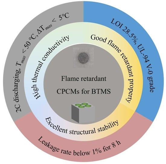
XRD results show that the mixture between the PCM and the additives in the flame retardant CPCM made in this experiment is a physical mixture, and no chemical reaction occurs. The flame retardant CPCM has excellent structural stability, and after eight hours of continuous heat, the leakage rate is kept within 1%.
(2)
CPCM25 with 25 wt% flame retardant achieved a V-0 rating in the UL-94 test, a thermal conductivity of 0.77 W·m−1·K−1, and a latent heat value of 87.63 J/g. In the thermogravimetric test, the residue at 800 °C reached 25.22%.
(3)
Battery modules with flame retardant CPCMs offer excellent thermal management. Under a 2C discharge rate, the Tmax of the battery pack remains below 50 °C, and the ΔTmax can be controlled within 5 °C. Even under a 3C discharge rate, the Tmax and ΔTmax are reduced by 30.31% and 29.53%, respectively.
This work has the significance of enhancing safety performance and extending battery life.

Author Contributions

Conceptualization, M.C. and Y.Y.; Methodology, M.C. and Y.C.; Investigation, J.Z. and Y.Y.; Writing—Review & Editing, Y.Y., M.C., M.Z., J.Z. and L.Z. All authors have read and agreed to the published version of the manuscript.

Funding

This research was funded by the National Natural Science Foundation of China (52204213), the Special Scientific Research Project of the School of Emergency Management of Jiangsu University (KY-B-09, KY-D-03), and the Project of Research on Educational Reform and Talent Development of School of Emergency Management of Jiangsu University (JG-03-03, JG-03-05, JG-04-08, JG-04-10).

Data Availability Statement

Data are contained within the article.

Conflicts of Interest

The authors declare no conflict of interest.

References

  1. Caineng, Z.O.; Xiong, B.; Huaqing, X.U.; Zheng, D.; Zhixin, G.E.; Ying, W.A.; Jiang, L.; Songqi, P.; Songtao, W. The role of new energy in carbon neutral. Pet. Explor. Dev. 2021, 48, 411–420. [Google Scholar]
  2. Wei, Y.M.; Chen, K.; Kang, J.N.; Chen, W.; Wang, X.Y.; Zhang, X. Policy and Management of Carbon Peaking and Carbon Neutrality: A Literature Review. Engineering 2022, 14, 52–63. [Google Scholar] [CrossRef]
  3. Holechek, J.L.; Geli, H.M.E.; Sawalhah, M.N.; Valdez, R. A Global Assessment: Can Renewable Energy Replace Fossil Fuels by 2050? Sustainability 2022, 14, 4792. [Google Scholar] [CrossRef]
  4. Chen, J.; Su, F.; Jain, V.; Salman, A.; Tabash, M.I.; Haddad, A.M.; Zabalawi, E.; Abdalla, A.A.; Shabbir, M.S. Does Renewable Energy Matter to Achieve Sustainable Development Goals? The Impact of Renewable Energy Strategies on Sustainable Economic Growth. Front. Energy Res. 2022, 10, 829252. [Google Scholar] [CrossRef]
  5. Liu, W.; Placke, T.; Chau, K.T. Overview of batteries and battery management for electric vehicles. Energy Rep. 2022, 8, 4058–4084. [Google Scholar] [CrossRef]
  6. Dai, H.; Jiang, B.; Hu, X.; Lin, X.; Wei, X.; Pecht, M. Advanced battery management strategies for a sustainable energy future: Multilayer design concepts and research trends. Renew. Sustain. Energy Rev. 2021, 138, 110480. [Google Scholar] [CrossRef]
  7. Feng, X.; Ren, D.; He, X.; Ouyang, M. Mitigating Thermal Runaway of Lithium-Ion Batteries. Joule 2020, 4, 743–770. [Google Scholar] [CrossRef]
  8. Wang, Q.; Ping, P.; Zhao, X.; Chu, G.; Sun, J.; Chen, C. Thermal runaway caused fire and explosion of lithium ion battery. J. Power Sources 2012, 208, 210–224. [Google Scholar] [CrossRef]
  9. Qi, X.; Sidi, M.O.; Tlili, I.; Ibrahim, T.K.; Elkotb, M.A.; El-Shorbagy, M.A.; Li, Z. Optimization and sensitivity analysis of extended surfaces during melting and freezing of phase changing materials in cylindrical Lithium-ion battery cooling. J. Energy Storage 2022, 51, 104545. [Google Scholar] [CrossRef]
  10. Mehrabi-Kermani, M.; Houshfar, E.; Ashjaee, M. A novel hybrid thermal management for Li-ion batteries using phase change materials embedded in copper foams combined with forced-air convection. Int. J. Therm. Sci. 2019, 141, 47–61. [Google Scholar] [CrossRef]
  11. Kong, D.; Peng, R.; Ping, P.; Du, J.; Chen, G.; Wen, J. A novel battery thermal management system coupling with PCM and optimized controllable liquid cooling for different ambient temperatures. Energy Convers. Manag. 2020, 204, 112280. [Google Scholar] [CrossRef]
  12. Chen, K.; Hou, J.; Song, M.; Wang, S.; Wu, W.; Zhang, Y. Design of battery thermal management system based on phase change material and heat pipe. Appl. Therm. Eng. 2021, 188, 116665. [Google Scholar] [CrossRef]
  13. Chen, F.; Huang, R.; Wang, C.; Yu, X.; Liu, H.; Wu, Q.; Qian, K.; Bhagat, R. Air and PCM cooling for battery thermal management considering battery cycle life. Appl. Therm. Eng. 2020, 173, 115154. [Google Scholar] [CrossRef]
  14. Weng, J.; Huang, Q.; Li, X.; Zhang, G.; Ouyang, D.; Chen, M.; Yuen, A.C.Y.; Li, A.; Lee, E.W.M.; Yang, W.; et al. Safety Issue on PCM-based Battery Thermal Management: Material Thermal Stability and System Hazard Mitigation. Energy Storage Mater. 2022, 53, 580–612. [Google Scholar] [CrossRef]
  15. Liu, X.; Zhang, Z.; Zhu, C.; Wang, F.; Zhao, D.; Li, Z.; Liu, Y.; Zhang, H.; Jiang, H. Experimental investigation on the effect of phase change materials for thermal management improvement of the fast charging power module. Case Stud. Therm. Eng. 2023, 42, 102711. [Google Scholar] [CrossRef]
  16. Heyhat, M.M.; Mousavi, S.; Siavashi, M. Battery thermal management with thermal energy storage composites of PCM, metal foam, fin and nanoparticle. J. Energy Storage 2020, 28, 101235. [Google Scholar] [CrossRef]
  17. Jiang, G.; Huang, J.; Fu, Y.; Cao, M.; Liu, M. Thermal optimization of composite phase change material/expanded graphite for Li-ion battery thermal management. Appl. Therm. Eng. 2016, 108, 1119–1125. [Google Scholar] [CrossRef]
  18. Li, J.; Tang, A.; Shao, X.; Jin, Y.; Chen, W.; Xia, D. Experimental evaluation of heat conduction enhancement and lithium-ion battery cooling performance based on h-BN-based composite phase change materials. Int. J. Heat Mass Transf. 2022, 186, 122487. [Google Scholar] [CrossRef]
  19. Wu, W.; Yang, X.; Zhang, G.; Ke, X.; Wang, Z.; Situ, W.; Li, X.; Zhang, J. An experimental study of thermal management system using copper mesh-enhanced composite phase change materials for power battery pack. Energy 2016, 113, 909–916. [Google Scholar] [CrossRef]
  20. Zou, D.; Ma, X.; Liu, X.; Zheng, P.; Hu, Y. Thermal performance enhancement of composite phase change materials (PCM) using graphene and carbon nanotubes as additives for the potential application in lithium-ion power battery. Int. J. Heat Mass Transf. 2018, 120, 33–41. [Google Scholar] [CrossRef]
  21. Atinafu, D.G.; Dong, W.; Wang, J.; Huang, X.; Wang, J.; Gao, H.; Wang, G. Synthesis and Characterization of Paraffin/Metal Organic Gel Derived Porous Carbon/Boron Nitride Composite Phase Change Materials for Thermal Energy Storage. Eur. J. Inorg. Chem. 2018, 48, 5167–5175. [Google Scholar] [CrossRef]
  22. Xiao, C.; Wu, X.; Dong, X.; Ye, G.; Zhang, G.; Yang, X. Ultrareliable Composite Phase Change Material for Battery Thermal Management Derived from a Rationally Designed Phase Changeable and Hydrophobic Polymer Skeleton. ACS Appl. Energy Mater. 2021, 4, 3832–3841. [Google Scholar] [CrossRef]
  23. Zhang, Y.; Huang, J.; Cao, M.; Liu, Z.; Chen, Q. A novel flexible phase change material with well thermal and mechanical properties for lithium batteries application. J. Energy Storage 2021, 44, 103433. [Google Scholar] [CrossRef]
  24. Hu, S.; Wang, S.; Zhang, Y.; Ma, C.; Wu, S.; Li, L. Effect of passive thermal management system on the electro-thermal performance of battery module. Int. J. Therm. Sci. 2023, 183, 107842. [Google Scholar] [CrossRef]
  25. Dai, X.; Kong, D.; Du, J.; Zhang, Y.; Ping, P. Investigation on effect of phase change material on the thermal runaway of lithium-ion battery and exploration of flame retardancy improvement. Process Saf. Environ. Prot. 2022, 159, 232–242. [Google Scholar] [CrossRef]
  26. Huang, Q.; Li, X.; Zhang, G.; Weng, J.; Wang, Y.; Deng, J. Innovative thermal management and thermal runaway suppression for battery module with flame retardant flexible composite phase change material. J. Clean. Prod. 2022, 330, 129718. [Google Scholar] [CrossRef]
  27. Zhang, P.; Hu, Y.; Song, L.; Ni, J.; Xing, W.; Wang, J. Effect of expanded graphite on properties of high-density polyethylene/paraffin composite with intumescent flame retardant as a shape-stabilized phase change material. Sol. Energy Mater. Sol. Cells 2010, 94, 360–365. [Google Scholar] [CrossRef]
  28. Sittisart, P.; Farid, M.M. Fire retardants for phase change materials. Appl. Energy 2011, 88, 3140–3145. [Google Scholar] [CrossRef]
  29. Zhang, J.; Li, X.; Zhang, G.; Wu, H.; Rao, Z.; Guo, J.; Zhou, D. Experimental investigation of the flame retardant and form-stable composite phase change materials for a power battery thermal management system. J. Power Sources 2020, 480, 229116. [Google Scholar] [CrossRef]
  30. Li, Y.; Wang, T.; Li, X.; Zhang, G.; Chen, K.; Yang, W. Experimental investigation on thermal management system with flame retardant flexible phase change material for retired battery module. Appl. Energy 2022, 327, 120109. [Google Scholar] [CrossRef]
  31. Xu, Z.; Chen, W.; Wu, T.; Wang, C.; Liang, Z. Thermal management system study of flame retardant solid–solid phase change material battery. Surf. Interfaces 2023, 36, 102558. [Google Scholar] [CrossRef]
  32. Lin, X.; Zhang, X.; Ji, J.; Liu, L.; Wu, Y.; Yang, M.; Lu, D.; Zheng, H. Development of flexible form-stable phase change material with enhanced electrical resistance for thermal management. J. Clean. Prod. 2021, 311, 127517. [Google Scholar] [CrossRef]
  33. Liao, H.; Duan, W.; Liu, Y.; Wang, Q.; Wen, H. Flame retardant and leaking preventable phase change materials for thermal energy storage and thermal regulation. J. Energy Storage 2021, 35, 102248. [Google Scholar] [CrossRef]
  34. Ma, Y.; Yang, H.; Zuo, H.; Zuo, Q.; He, X.; Chen, W.; Wei, R. EG@Bi-MOF derived porous carbon/lauric acid composite phase change materials for thermal management of batteries. Energy 2023, 272, 127180. [Google Scholar] [CrossRef]
  35. Song, G.; Ma, S.; Tang, G.; Yin, Z.; Wang, X. Preparation and characterization of flame retardant form-stable phase change materials composed by EPDM, paraffin and nano magnesium hydroxide. Energy 2010, 35, 2179–2183. [Google Scholar] [CrossRef]
  36. Kempel, F.; Schartel, B.; Marti, J.M.; Butler, K.M.; Rossi, R.; Idelsohn, S.R.; Onate, E.; Hofmann, A. Modelling the vertical UL 94 test: Competition and collaboration between melt dripping, gasification and combustion. Fire Mater. 2015, 39, 570–584. [Google Scholar] [CrossRef]
  37. Liu, W.; Wang, Z.; Su, S.; Wu, H.; Sun, M.; Tang, L. Synergistic flame retardancy of ZnO and piperazine pyrophosphate/melamine cyanurate in polypropylene. J. Vinyl Addit. Technol. 2023, 29, 202–219. [Google Scholar] [CrossRef]
  38. Ma, Y.; Wang, J.; Xu, Y.; Wang, C.; Chu, F. Effect of zinc oxide on properties of phenolic foams/halogen-free flame retardant system. J. Appl. Polym. Sci. 2015, 132, 42730. [Google Scholar] [CrossRef]
  39. Wu, W.; Liu, J.; Liu, M.; Rao, Z.; Deng, H.; Wang, Q.; Qi, X.; Wang, S. An innovative battery thermal management with thermally induced flexible phase change material. Energy Convers. Manag. 2020, 221, 113145. [Google Scholar] [CrossRef]
  40. Pradeep, G.M.; Sankaramoorthy, T.; Elango, M.; Kumar, T.N.; Girimurugan, R. Structural analysis and mechanical properties of thermal battery by flexible phase change materials [P.C.M.]. Mater. Today Proc. 2021, 56, 3196–3200. [Google Scholar] [CrossRef]
Figure 1. The preparation process of CPCMs and the produced samples.
Batteries 09 00378 g001
Figure 2. Diagram of the battery experimental test system.
Batteries 09 00378 g002
Figure 3. (a) Images of different samples before and after continuous heating at 70 °C; (b) Leakage rate curve diagram of different samples.
Batteries 09 00378 g003
Figure 4. XRD patterns of different samples.
Batteries 09 00378 g004
Figure 5. SEM morphology of (a,b) the worm-like structure of EG; (c) CPCM15; (d) CPCM20; (e) CPCM25; (f) CPCM30.
Batteries 09 00378 g005
Figure 6. Thermal conductivity of different CPCM samples.
Batteries 09 00378 g006
Figure 7. DSC curves of different CPCM samples.
Batteries 09 00378 g007
Figure 8. TG curve of different samples.
Batteries 09 00378 g008
Figure 9. Vertical combustion photos of different CPCMs.
Batteries 09 00378 g009
Figure 10. Cell temperature curve (a) 1C; (b) 2C; (c) 3C.
Batteries 09 00378 g010
Figure 11. Temperature curve of the battery module (a) 1C; (b) 2C; (c) 3C. Temperature difference curve of the battery module (d) 1C; (e) 2C; (f) 3C.
Batteries 09 00378 g011aBatteries 09 00378 g011b
Table 1. Proportion of the flame retardant composite PCMs.
SampleMass Content (wt%)
PAHDPEEGFR
PA100000
CPCM156020515
CPCM205520520
CPCM255020525
CPCM304520530
Table 2. Flammability of different samples.
PACPCM15CPCM20CPCM25CPCM30
UL-94NRNRNRV-0NR
LOI17.7%22.4%23.8%28.5%26.1%
Disclaimer/Publisher’s Note: The statements, opinions and data contained in all publications are solely those of the individual author(s) and contributor(s) and not of MDPI and/or the editor(s). MDPI and/or the editor(s) disclaim responsibility for any injury to people or property resulting from any ideas, methods, instructions or products referred to in the content.

