Article

State of Charge and Temperature Joint Estimation Based on Ultrasonic Reflection Waves for Lithium-Ion Battery Applications

1
State Key Laboratory of Radio Frequency Heterogeneous Integration, Shenzhen University, Shenzhen 518060, China
2
College of Physics and Optoelectronic Engineering, Shenzhen University, Shenzhen 518060, China
3
School of Electrical Engineering and Automation, Harbin Institute of Technology, Harbin 150001, China
*
Authors to whom correspondence should be addressed.
Batteries 2023, 9(6), 335; https://doi.org/10.3390/batteries9060335
Submission received: 9 May 2023 / Revised: 8 June 2023 / Accepted: 16 June 2023 / Published: 20 June 2023

Abstract

:
Accurate estimation of the state of charge (SOC) and temperature of batteries is essential to ensure the safety of energy storage systems. However, it is very difficult to obtain multiple states of the battery with fewer sensors. In this paper, a joint estimation method for a lithium iron phosphate battery’s SOC and temperature based on ultrasonic reflection waves is proposed. A piezoelectric transducer is affixed to the surface of the battery for ultrasonic–electric transduction. Ultrasonic signals are excited at the transducer, transmitted through the battery, and transmitted back to the transducer by reaching the underside of the battery. Feature indicator extraction intervals of the battery state are determined by sliding–window matching correlation analysis. Virtual samples are used to expand the data after feature extraction. Finally, a backpropagation (BP) neural network model is applied to the multistate joint estimation of a battery in a wide temperature range. According to the experimental results, the root mean square error (RMSE) of the lithium-ion battery’s SOC and temperature estimation results is 7.42% and 0.40 °C, respectively. The method is nondestructive and easy to apply in battery management systems. Combined with the detection of gas production inside the battery, this method can improve the safety of the battery system.

1. Introduction

Climate change is a major threat to the sustainable survival of human society. Reducing carbon emissions has become a major global issue of universal concern to the international community [1,2,3,4,5]. The use of electric vehicles (EVs) can save energy and reduce carbon dioxide emissions, but with the increase in the use of electric cars, the safety of battery energy storage systems is widely considered [6,7,8,9]. EVs mainly use lithium-ion batteries, so determining the battery’s SOC and temperature can help the system make comprehensive decisions and improve system safety. The battery SOC estimation method can help users to develop reasonable usage strategies to ensure that the battery operates within the normal charging and discharging range to avoid irreversible changes in the positive active substance structure and abnormal battery capacity attenuation [10]. Battery temperature changes can reduce the reliability of battery SOC estimation and can even pose a risk of thermal runaway; accurate battery SOC estimation in temperature–varying environments can avoid battery thermal runaway [11,12]. The methods reported in the literature [13,14] mainly use voltage and current sensors in the battery management system to collect the electrical characteristic parameters of the batteries. Combined with battery models and advanced algorithms, the battery’s SOC can be estimated [15]. The temperatures of the battery are mainly measured by a small number of temperature sensors in the battery system. However, it is difficult to determine the temperature of each battery in the battery energy storage system by employing a few temperature sensors, which is not conducive to battery safety management. In this context, how to use a few sensors to jointly and accurately estimate battery SOC and temperature is very important.
Recently, the utilization of ultrasonic nondestructive testing technology has become prevalent across various industrial sectors [16,17,18]. The rapid development of ultrasonic technology provides a new technical tool for estimating the states of batteries. Some methods of determining battery states using ultrasonic sensors have been reported. Bhanu et al. [19] proposed an integrated technique for the health monitoring of lithium-ion batteries, which involves attaching an ultrasonic transducer pulser and receiver to the external surfaces of a lithium-ion cell. This technique allows for the nondestructive evaluation of the internal condition of vital interfaces within the cell. Hsieh et al. [20] demonstrated that acoustic time of flight (TOF) experiments can measure the SOC and state of health (SOH) of almost any closed battery. They proposed an acoustic conservation law model that describes the state of charge of a standard battery. Additionally, experimental results showed that both SOC determination and irreversible physical changes in lithium-ion 18650 and alkaline LR6 (AA) batteries could be measured. Gold et al. [21] proposed a method for estimating the SOC of a battery by directly measuring its charge using a variety of positive active materials based on the linear correlation between the ultrasonic signal and the actual charging state. The changes in the ultrasonic signal are related to the lithium content absorbed by the negative graphite, allowing the battery’s SOC to be estimated without a reference electrode. Ladplia et al. [22] analyzed the feasibility of using ultrasonic guided waves to detect the SOC and SOH of a pouch lithium-ion battery. They fixed piezoelectric ceramic wafers on the surface of the battery to generate ultrasonic waves and convert the received ultrasonic echoes into electrical signals. The changes in the TOF and signal amplitude (SA) of the guided waves were found to be closely related to electrochemical charge–discharge cycles and battery aging. Copley et al. [23] found that the correlation between ultrasonic response and battery capacity is much stronger than that with battery voltage. They also confirmed that ultrasound can detect density changes during the cycles between positive and negative electrodes. The relationship between the ultrasonic response and battery capacity is approximately linear. Zhao et al. [24] proposed a joint estimation method for lithium-ion battery SOC and SOH based on ultrasonic guided waves. They used a scanning laser Doppler vibrometer (SLDV) system to capture the fast propagation process of ultrasonic guided waves. By analyzing the signals in the time domain, frequency domain, and time–frequency distribution, they obtained three guiding wave parameters, including signal amplitude, TOF, and power spectral density, to indicate the battery’s SOC in the charge and discharge processes. The ultrasonic guided wave parameters showed a good corresponding relationship with the battery’s SOC and SOH. Sun et al. [25] monitored the battery’s charging and discharging processes at different ultrasonic frequencies of 750 kHz, 1.0 MHz, and 1.5 MHz. The velocities of the ultrasonic waves with three frequencies showed an approximately linear relationship with the battery’s SOC. The analysis results could be used for battery SOC estimation. It was also found that the attenuation of ultrasonic signal amplitude is related to the process of material phase transition during battery charging and discharging. Galiounas et al. [26] demonstrated the use of artificial neural network regression models to estimate SOC based on acoustic signatures. Holistic waveform treatment provides a more robust approach for correlating acoustic signatures with electrochemical states. Furthermore, they demonstrated that transforming the data into the frequency domain can significantly reduce the complexity of the problem while improving the accuracy of estimation. The results showed that the average estimation error was 0.75%. Li et al. [27] used a piezoelectric ceramic ultrasonic transducer to detect batteries by obtaining ultrasonic guided wave signals. Considering the frequency response of the transducer and the battery, the multi-frequency response characteristics of the battery were analyzed. Multiple features with multi-frequency excitation were selected. The RMSE of the battery’s SOC estimation result was less than 2.36%.
Ultrasonic nondestructive testing techniques have been found to be applicable for estimating both the SOC and SOH of batteries. However, some problems remain unresolved. Since a lithium-ion battery is a solid–liquid hybrid medium, changes in electrolyte viscosity and density should not be ignored. Battery state estimation algorithms based on limited ultrasonic feature parameters such as SA and TOF may result in instability. To better estimate the states of the battery, it is necessary to consider the solid–liquid mixed structure of the battery, select multiple feature indicators, and analyze the effective intervals of ultrasonic signals. Additionally, due to the small number of experimental samples, it is necessary to adopt appropriate methods to supplement the data. As the ambient temperature of the battery is variable, battery temperature information cannot be ignored when considering the safety of battery operation. If temperature changes are not considered, battery SOC estimation methods often fail. A joint estimation method of battery SOC and temperature based on ultrasonic waves has not been reported.
This paper presents a new method for the joint estimation of lithium-ion battery SOC and temperature using ultrasonic reflected waves. The main contents are as follows: In Section 2, the transmission mechanism of ultrasonication in batteries is introduced. A multistate joint battery estimation method is developed in Section 3. The main feature indicators are introduced. The optimal feature interval is determined using sliding–window matching correlation analysis. A virtual sample generation algorithm is used to enhance the richness of the data samples. A battery state estimation model using a BP neural network was designed to estimate the SOC and temperature of the battery. In Section 4, the experimental details are described. The results and discussion are presented in Section 5. The influence of the battery’s SOC and temperature on the ultrasonic signal is analyzed. Multiple features in ultrasonic waves are identified and analyzed. Finally, the effectiveness of the proposed method is verified through a set of battery experiments.

2. Mechanisms

2.1. Ultrasonic Transmission Mechanism

A battery is a multilayer medium that includes many layers of positive and negative electrodes, current collectors, and separators. The electrolyte fills the porous structure of the electrode and separator. The transmission of ultrasonic waves in a battery can be viewed as transmission in a multilayer medium with a mixture of solid and liquid. One of the fundamental characteristic parameters of the ultrasonic wave in a medium is the wave velocity. When the size of the medium is much larger than the wavelength of the ultrasonic wave, it can be assumed to be an infinite medium. The velocity of the ultrasonic primary wave in the infinite medium CL can be defined as follows:
C L = E ( 1 μ ) ρ ( 1 + μ ) ( 1 2 μ )
where E is the elastic modulus of the medium, ρ is the density, and μ is the Poisson’s ratio of the medium.
For the liquid medium, the primary wave can be transmitted. However, shear waves or surface waves cannot be transmitted. The velocity of ultrasonic primary waves in a liquid medium C can be defined as follows:
C = K ρ
where K is the bulk modulus and ρ is the density of the medium.
Another characteristic parameter of ultrasonic waves’ transmission in the medium is wave attenuation. The diffusion, scattering, and absorption of ultrasonic waves by the medium can cause attenuation. The diffusion phenomenon of the ultrasonic beam causes diffusion attenuation. Scattering attenuation occurs due to differences in acoustic impedance at interfaces within the medium. The particle viscosity of the medium and the heat conduction process in the medium can cause absorption attenuation. In this paper, we mainly consider the influence of the change in the characteristics of the battery on the attenuation of ultrasonic wave transmission. The difference in diffusion attenuations is ignored. According to ultrasonic wave transmission theory [28], scattering attenuation and absorption attenuation can be expressed by exponential equations:
A = A 0 e α L
where A0 is the initial amplitude of the ultrasonic wave, A is the echo amplitude of the ultrasonic wave, L is the transmission distance of the ultrasonic wave in a non-uniform medium, and α is the attenuation coefficient.
Scattering attenuation: When the ultrasonic wave travels in the medium, the inhomogeneity of the medium causes the tiny interface to produce different acoustic impedances so that the sound wave propagates in different directions, causing attenuation of the ultrasonic energy. The scattering attenuation coefficient αs is represented by
α s = 8 3 π 4 r 3 f 4 c 4
where f is the ultrasonic frequency, r is the radius of the particle, and c is the wave velocity.
Viscous attenuation: When ultrasonic waves are transmitted in the medium, the dielectric points attached to the container wall are subject to great binding force, resulting in friction loss between layers. As a result, ultrasonic waves decay in a medium [29]. The viscous attenuation coefficient is represented by
α η = 2 π 2 f 2 η ρ c 3
where η is the viscosity of the medium, ρ is the density of the inhomogeneous medium, and c is the wave velocity.
Heat conduction attenuation: When an ultrasonic wave is transmitted through a heterogeneous medium, the medium is affected by ultrasonic vibration. The temperature of the medium changes slightly, as does the volume. A temperature gradient is generated between adjacent regions, leading to heat transfer in high and low–temperature regions. The heat conduction attenuation coefficient is represented by
α ξ = 2 π 2 f 2 χ ρ c 3 ( 1 c v 1 c p )
where χ is the heat conduction coefficient, cv is the specific heat of the medium at constant volume, and cp is the specific heat at constant pressure of the medium.
According to the analysis of ultrasonic transmission in a non-uniform medium [30], the attenuations can be calculated. When the ultrasonic frequency is 200 kHz, the wave velocity is 1850 m/s, and the medium density is 1150 kg/m3, the influence factor of scattering attenuation is the largest, accounting for 91.77%, followed by the viscous attenuation factor of absorption attenuation, which is 8.22%, and the heat conduction attenuation factor of absorption attenuation, which is 0.01%. The influence of the scattering attenuation coefficient is much greater than that of the viscous and heat conduction attenuation coefficients.

2.2. Relationship between Ultrasonic Signal and Battery States
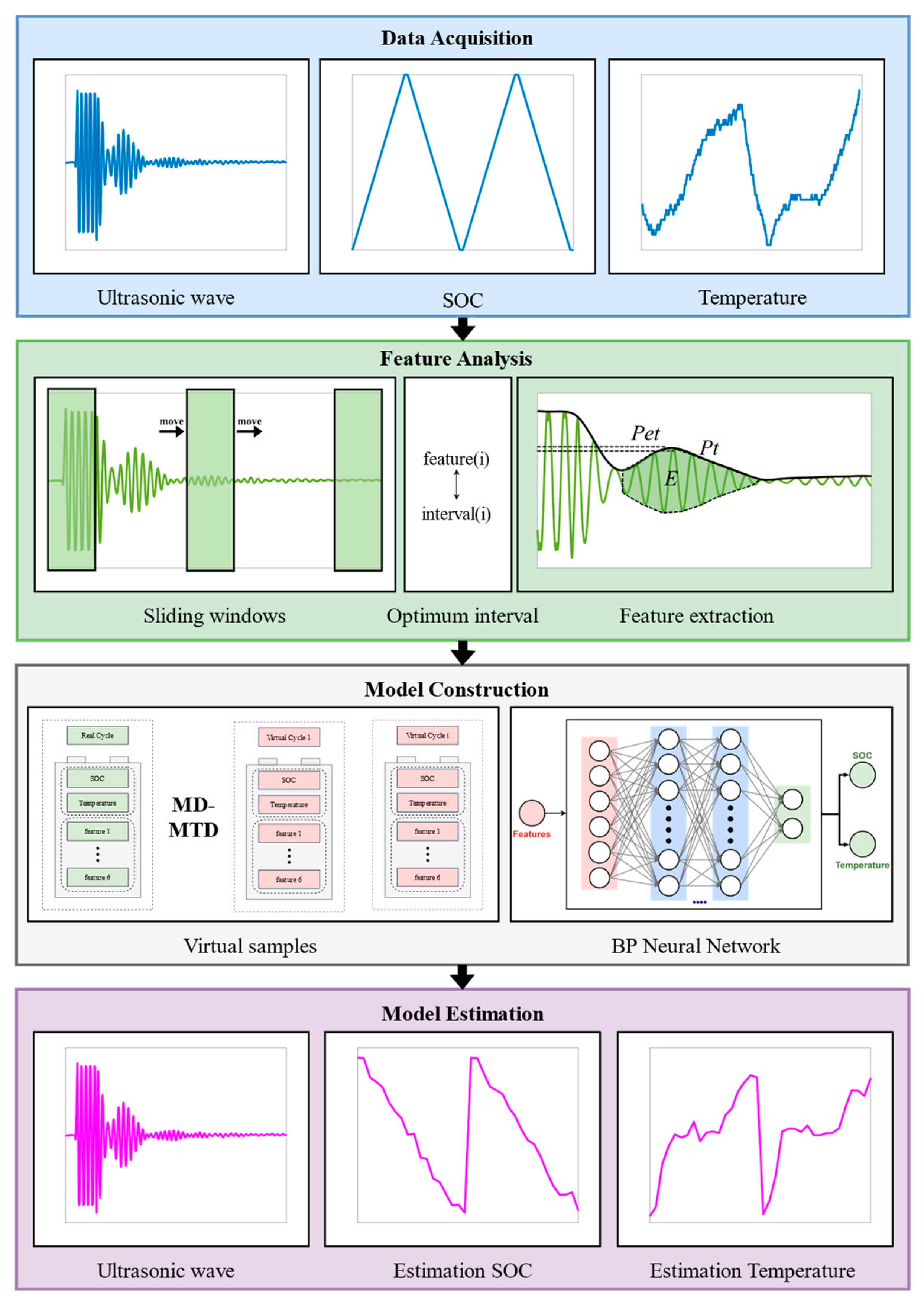
During battery discharge, lithium ions leave the graphite particles in the negative electrode and enter the electrolyte. The ions diffuse through a separator to the surface of the positive electrode’s lithium iron phosphate crystal and are embedded into its lattice structure. In contrast, during the battery charging process, the lithium ions in the positive electrode exit the lattice structure into the electrolyte and re-enter the layered structure of the negative graphite particles through the separator. The constant motion of lithium ions in the charge–discharge cycle leads to the expansion and contraction of the lattice volume of the electrode material and changes the damping characteristics of the material. Furthermore, structural parameters such as the elastic modulus of the electrode material also change. During the charging process, the elastic modulus of the positive electrode material decreases, while that of the graphite negative electrode material increases [31]. Additionally, the electrode particles undergo some degree of volume expansion, leading to changes in the porosity of the electrode sheet and its filling state. Ultrasonic signals are highly sensitive to changes in material structural parameters. The characteristic changes in battery materials during charging and discharging can be evaluated by the changes in ultrasonic signal attenuation, propagation time, etc.
The positive and negative electrodes, current collectors, and separators are all solid materials. The influence of temperature changes on the acoustic properties of these materials is limited. However, the electrolyte inside the battery mainly uses a mixed solvent system, which is greatly affected by temperature. The common electrolyte is made up of 95% carbonate solvent. The main components of the electrolyte include dimethyl carbonate (DMC), diethyl carbonate (DEC), ethyl methyl carbonate (EMC), and ethylene carbonate (EC). Temperature changes can cause variations in the density and viscosity of the electrolyte, which can affect the compatibility between the electrolyte, the positive and negative electrodes, and the separator. The conductivity of the mixed–solvent–system electrolyte can decrease sharply at low temperatures. Table 1 and Table 2 show the density and viscosity of DMC at different temperatures, respectively [32]. For example, the medium density decreases and the ultrasonic wave velocity increases due to the temperature increase. As a result, the scattering attenuation coefficient and the echo signal amplitude increase, while the amplitude of the transmitted wave decreases.
Based on the analysis, changes in the battery’s SOC can lead to changes in the lithium-ion filling state, elastic modulus, and damping characteristics of the electrode materials inside the battery. Similarly, changes in battery temperature can affect the density and viscosity of the electrolytes, as well as the structural parameters of the battery. As a result, the changes in ultrasonic wave transmission inside the battery can be used to evaluate the states of lithium-ion batteries.

3. Methods

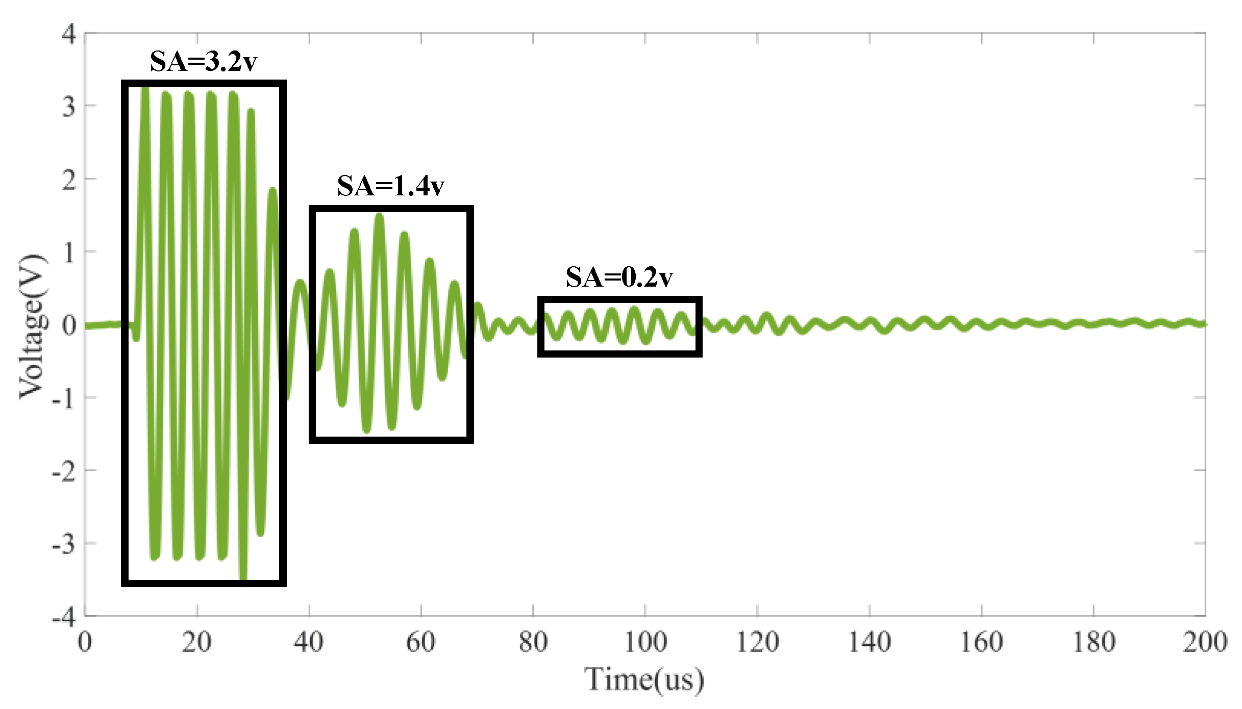
3.1. Feature Indicators of the Ultrasonic Signal

When the square–wave signals are loaded into the piezoelectric transducer, ultrasonic waves are excited and propagate on the battery. After a few microseconds, the reflected wave can be received by the same piezoelectric transducer. As shown in Figure 1, the reflected ultrasonic wave of a battery has three parts: Part 0 is the ultrasonic echo wave reflected on the battery’s upper surface. The echo signal at approximately 20 µs belongs to the signal that has not completely penetrated the battery, and the signal has a small TOF and large signal amplitude (SA, 3.2 V). Part 1 (40–70 µs) is the ultrasonic echo signal that penetrates the whole battery. The TOF of the signal is larger, and the SA is smaller (1.4 V). Part 2 (90–110 µs) is the echo signal received after the second reflection inside the battery. This signal has the largest TOF and the smallest SA (0.2 V).
In order to better analyze the three parts of the ultrasonic waves, six feature indicators were selected for battery state estimation. The indicators are defined in Table 3. The feature indicators can be classified into two distinct categories. The ultrasonic signal attenuation inside the battery can be indicated by time domain feature parameters, such as the time domain peak (Pt), time domain envelope peak (Pet), and energy integral parameter (E). The feature parameters have strong correlations with the attenuation coefficient in the medium and can be used to characterize the changes in the internal structural parameters of the battery as the battery state changes. Waveform feature indicators are used to characterize the waveform shape of ultrasonic time−domain signals. The feature parameters include the waveform index (W), kurtosis coefficient (K), and shape coefficient (S). The waveform feature indicators can reflect the waveform aliasing phenomenon when ultrasonic waves are transmitted in the medium. The ultrasonic wave received by the piezoelectric transducer is the result of the superposition of the direct waves and the reflected waves.
In Table 3, A represents the time domain wave of the ultrasonic signal, a and b represent the sampling points at the beginning and end of the signal, respectively, N represents the number of sampling points in the signal, and L represents the length of the signal.

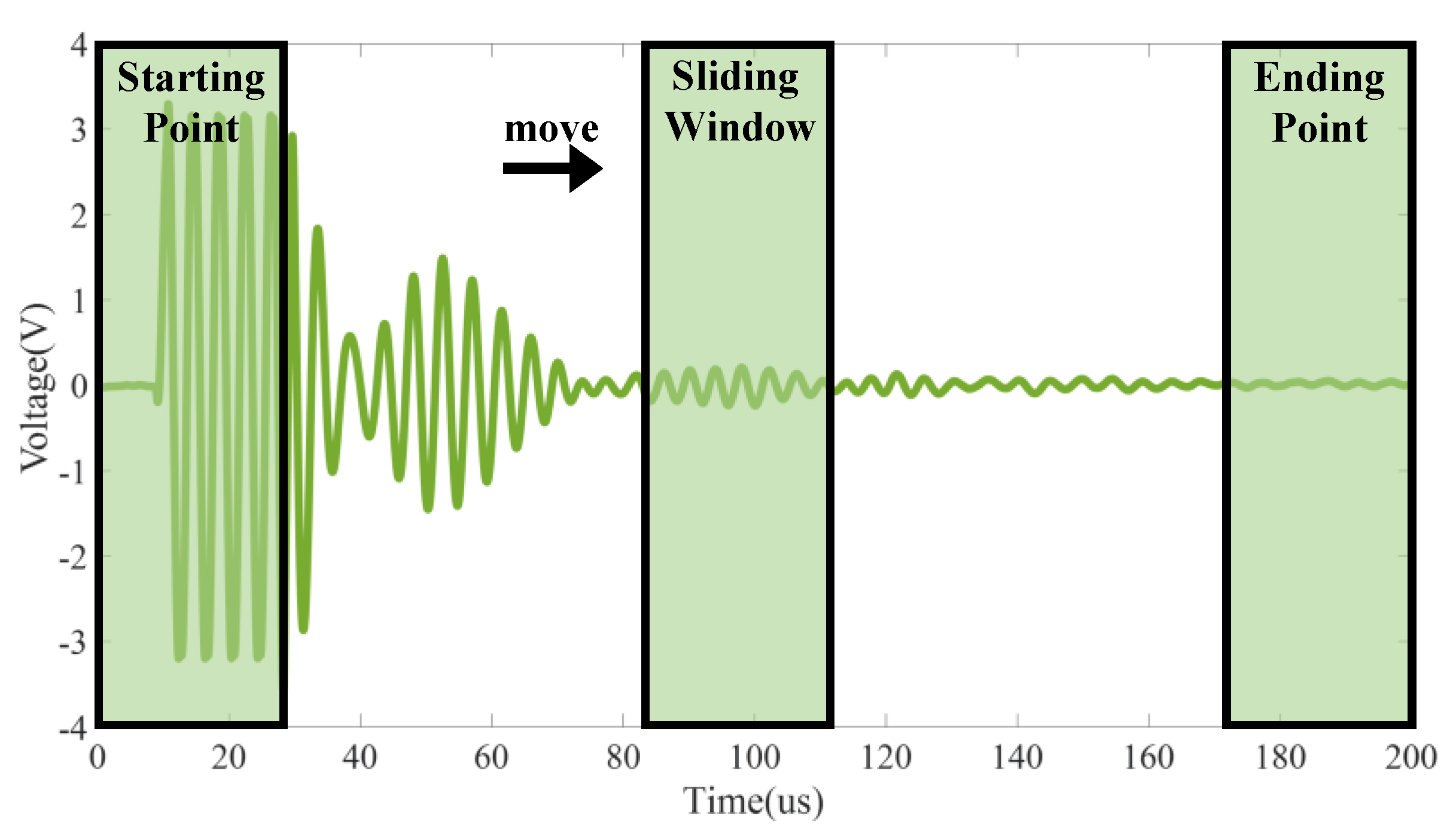
3.2. The Optimal Intervals of the Signal

If the ultrasonic reflection waves are analyzed directly, the waves may contain many invalid data points, which have poor correlation with battery states, or effective data may not have been extracted from the ultrasonic reflected waves. In order to better estimate the states of the battery, it is necessary to optimize the data interval for feature indicator extraction. On this basis, a sliding–window matching correlation analysis method is proposed to determine the optimal application range for ultrasonic reflection wave feature extraction.
The ultrasonic reflection waves collected by the oscilloscope have 10,000 sampling points. The window size was set to 1500 sampling points, the starting point was set to 1:1500, and the ending point was set to 8501:10,000. The windows slid from the starting point and ended at the ending point. The window was saved once for each sliding time, and a total of 8501 windows were obtained, as shown in Figure 2.
For the series of windows, Spearman’s rank correlation coefficients were first used to calculate their correlation with the battery’s SOC. The correlation in different intervals is shown in Table 4. In addition to part 1 and part 2, there are other intervals that are highly correlated with the battery’s SOC. The selected interval is called the optimal feature extraction interval. Compared with part 1, the waveform index, kurtosis coefficient, and shape coefficient have a higher correlation with the battery’s SOC. Compared with part 2, the time domain peak, time domain envelope peak, and energy integral have a higher correlation with the battery’s SOC.

3.3. Virtual Sample Generation

Battery charge–discharge tests are time–consuming. The number of samples obtained in experiments is often very limited, resulting in insufficient samples for machine learning models. In order to solve this problem, a multi-distribution global trend diffusion (MD-MTD) method [33,34] was used in this study to improve the richness of samples in the dataset for battery model training. The characteristic parameters for battery state estimation model training consist of six features of the ultrasonic wave, as stated in Section 3.2. Multiple virtual samples are generated by using the MD-MTD method, in which each virtual sample has six feature indicators. In this way, the indicators of the N virtual samples can be generated based on the features of some samples obtained in one discharge cycle of the battery. The MD-MTD algorithm operates based on the following fundamental principle:
Step one: Compute the variance of the original samples (S2) X = {x1, x2 … xi}, data center (C), left skewness (LS) and right skewness (RS):
S 2 = j = 1 i ( X j X ¯ ) 2 i 1
C = { x ( i + 1 ) / 2 , i = 1 , 3 , 1 2 ( x i / 2 + x ( i + 1 ) / 2 ) , i = 2 , 4 ,
L S = N 1 N 1 + N 2 + δ
R S = N 2 N 1 + N 2 + δ
where N1 indicates the number of samples lower than C, N2 indicates the number of samples higher than C, δ is a correction factor, and i represents the total amount of data in X.
Step two: Determine the acceptable range for the original samples:
L = { C L S × 2 S 2 N 1 × 20 ln ( 10 ) , L < min min , L min
R = { C + R S × 2 S 2 N 2 × 20 ln ( 10 ) , R > max max , R max
where L represents the left end and R represents the right end.
Step three: Generate virtual samples in the extending areas, using a uniform distribution, and subsequently apply the fitness function to select virtual samples that satisfy the given constraints:
{ L V j R j = 1 i ( O V j ) i f v
where O signifies the original sample, Vj signifies the j-th virtual sample, and the fit value (fv) serves as a control parameter for regulating the similarity between the two samples.
As illustrated in Figure 3, three candidate fit values are employed for generating the virtual samples, and lines of different colors represent generated virtual samples. The similarity between the original samples and the virtual samples is regulated by the fit value. When the fit value is low, there is a high level of similarity between the original samples and the virtual samples, which will cause the generalization of the virtual samples to not be significantly improved. With the increase in the fit value, the generalization function of the virtual samples becomes more apparent. Nevertheless, when the fit value reaches a high value, the disparity between the two samples becomes significant, potentially resulting in noticeable deviation. Taking the variation of the kurtosis coefficient (K) as an example, the fit values of Figure 3a,d, Figure 3b,e, and Figure 3c,f are set to 0.001, 0.003, and 0.006, respectively. When the fit value is 0.003, the virtual sample curve shows a similar trend to the original sample curve. As a result, the fit value was set to 0.003 in this paper.

3.4. BP Neural Network Model
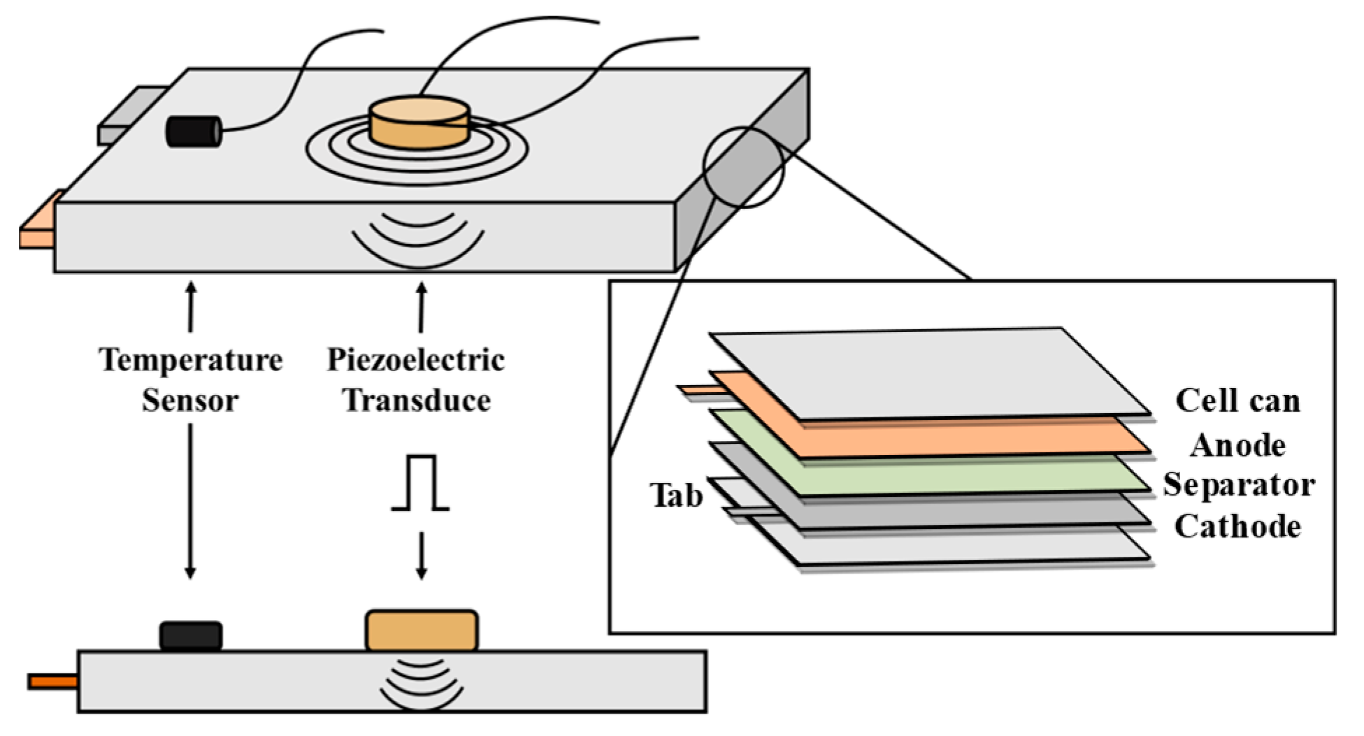
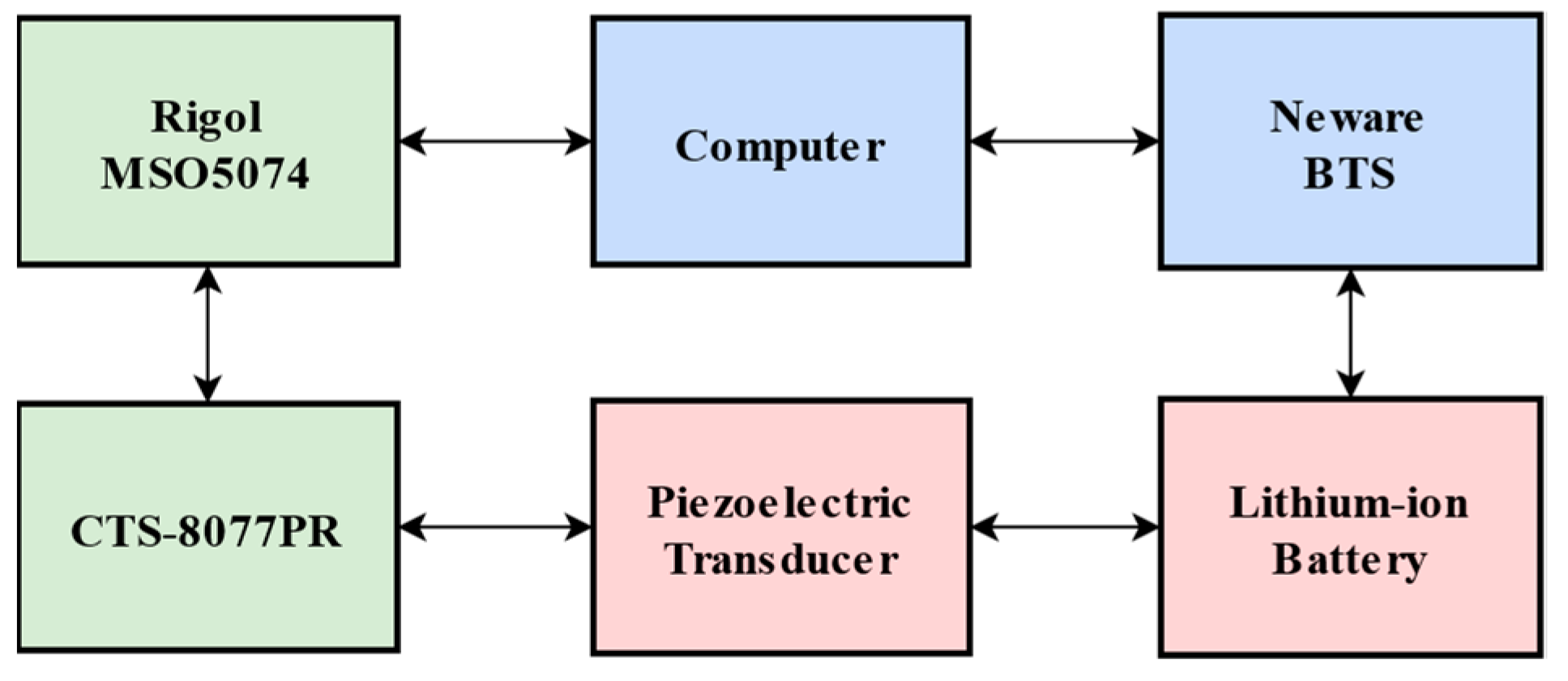
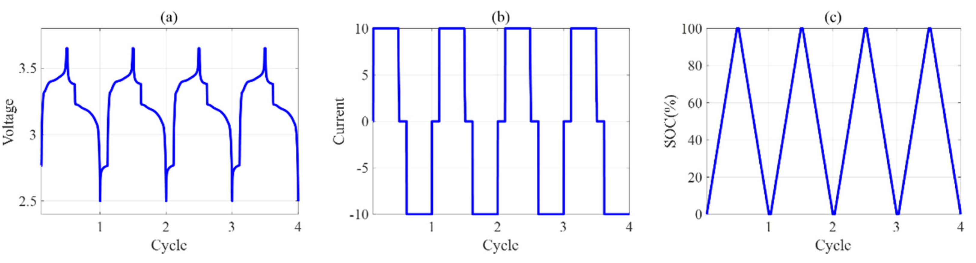
In order to establish a data–driven model linking ultrasonic wave features and battery states, a BP neural network model was adopted in this study [35]. This is a multilayer feedforward neural network model trained using the error backward propagation algorithm. The neural network can learn and store a large number of inputs–outputs mode–mapping relationships. The learning rule is to use the fastest descent method through backpropagation to constantly adjust the weight item and bias item of the network, so as to minimize the network error function value. Battery state estimation results can be obtained accurately. The updated formulae of the weight item and bias item for model training are as follows:
w = w η E w h j
b = b E b j l
where w is the update weight item, b is the update bias item, E is the error function, and η is the learning rate, usually set to 0.1–0.3.
The neural network model takes six feature indicators of ultrasonic waves as input data. The battery’s SOC and temperature are regarded as the output of the model. Table 5 shows the parameters of the BP neural network model. The battery’s SOC labels are set with 18 points (100–0%). The battery’s mean temperature labels are set with 4 points (26 °C, 34 °C, 42 °C, and 50 °C). Based on the results of the battery experiments, when the temperature of the battery increases, the stability of the ultrasonic wave decreases. Herein, the temperature point (46 °C) is added between the high temperatures (42 °C and 50 °C). Ultimately, there are 5 mean temperature labels (26 °C, 34 °C, 42 °C, 46 °C, and 50 °C) in total.
Figure 4 presents the proposed structure for joint estimation of battery SOC and temperature based on ultrasonic reflection wave methods. In the first part of the structure, data acquisition includes ultrasonic reflection wave data acquisition, SOC acquisition, and battery surface temperature acquisition. In the second component of the structure, sliding–window analysis is used to pick the optimal interval with high correlation, and feature extraction is conducted on the above interval. The BP neural network model is constructed and trained in the third part of structure, with the MD-MTD algorithm applied to generate virtual samples. In the fourth part of structure, by inputting the ultrasonic reflected wave signal of the battery, the SOC and temperature of the battery under the corresponding state can be estimated.

4. Experiments

Compared with the ultrasonic transmitted wave and the ultrasonic guided wave, a simpler ultrasonic reflection wave was selected for battery state estimation. In order to verify the method, a set of battery tests were conducted on a lithium iron phosphate prismatic cell (LISHEN, 20 Ah, 132 × 70 × 27 mm Manufacturer: LISHEN, city: Tianjin, country: China, sourced: Taobao.). A piezoelectric transducer (15 × 0.4 mm) fixed on the center of the battery surface excited and collected the ultrasonic wave, and a temperature sensor (NEWARE CA-4008-1U-TX Manufacturer: NEWARE, city: Shenzhen, country: China, sourced: Factory procurement.) collected the temperature of the battery’s surface. Both of them were solidified on the battery surface with cyanoacrylate glue (DELI Super glue Manufacturer: DELI, city: unknown, country: China, sourced: Jd.). The layout of the sensors is shown in Figure 5. The excitation waveform used in the experiment was a square wave with a frequency of 100 kHz. Clear and obvious envelopes of the ultrasonic signal could be observed.
The piezoelectric transducer is driven by an ultrasonic pulser–receiver (GOWORLD CTS-8077PR Manufacturer: GOWORLD, city: Shantou, country: China, sourced: Factory procurement.). Meanwhile, the ultrasonic echo wave is also processed by the ultrasonic pulser–receiver. The amplified signal is collected by an oscilloscope (RIGOL MSO5074). The battery testing system (NEWARE CT-4008-5V40A Manufacturer: NEWARE, city: Shenzhen, country: China, sourced: Factory procurement.) is used to control the battery’s charge–discharge and collect the battery surface temperature data. It works simultaneously with the ultrasonic testing system. A schematic diagram of the experimental battery system is shown in Figure 6.
Figure 7 shows the battery charge–discharge profile of the experiment. The battery’s terminal voltage, load current, and SOC were collected. The battery was charged in constant–current constant–voltage (CCCV) mode, with a current limitation of 2 A, and discharged in constant–current (CC) mode. The upper cutoff voltage was 3.65 V, and the lower cutoff voltage was 2.5 V. Each battery charge–discharge cycle took approximately 4 h. During the experiment, the battery was placed in a small temperature chamber (KEJING DZF-6050 Manufacturer: KEJING, city: Shenzhen, country: China, sourced: Factory procurement.). The temperature was set to 26 °C, 34 °C, 42 °C, 46 °C, and 50 °C, sequentially. The ultrasonic reflected wave data were recorded during the battery charge–discharge cycle at different temperatures.

5. Results and Discussion

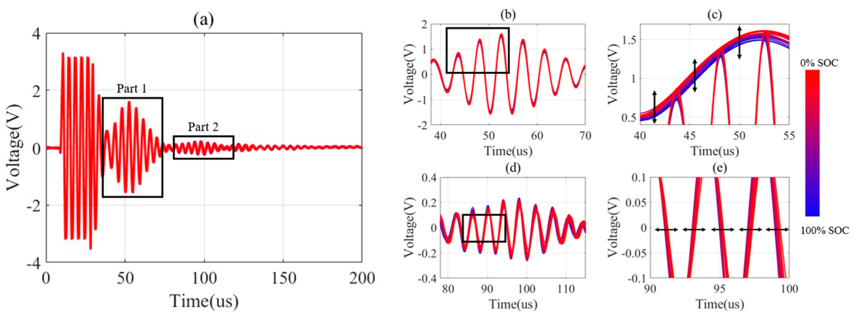
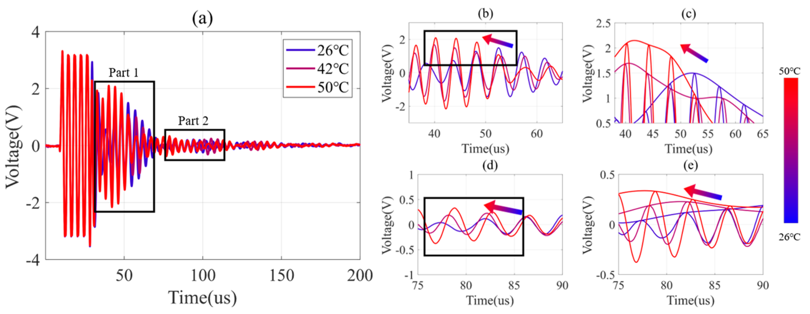
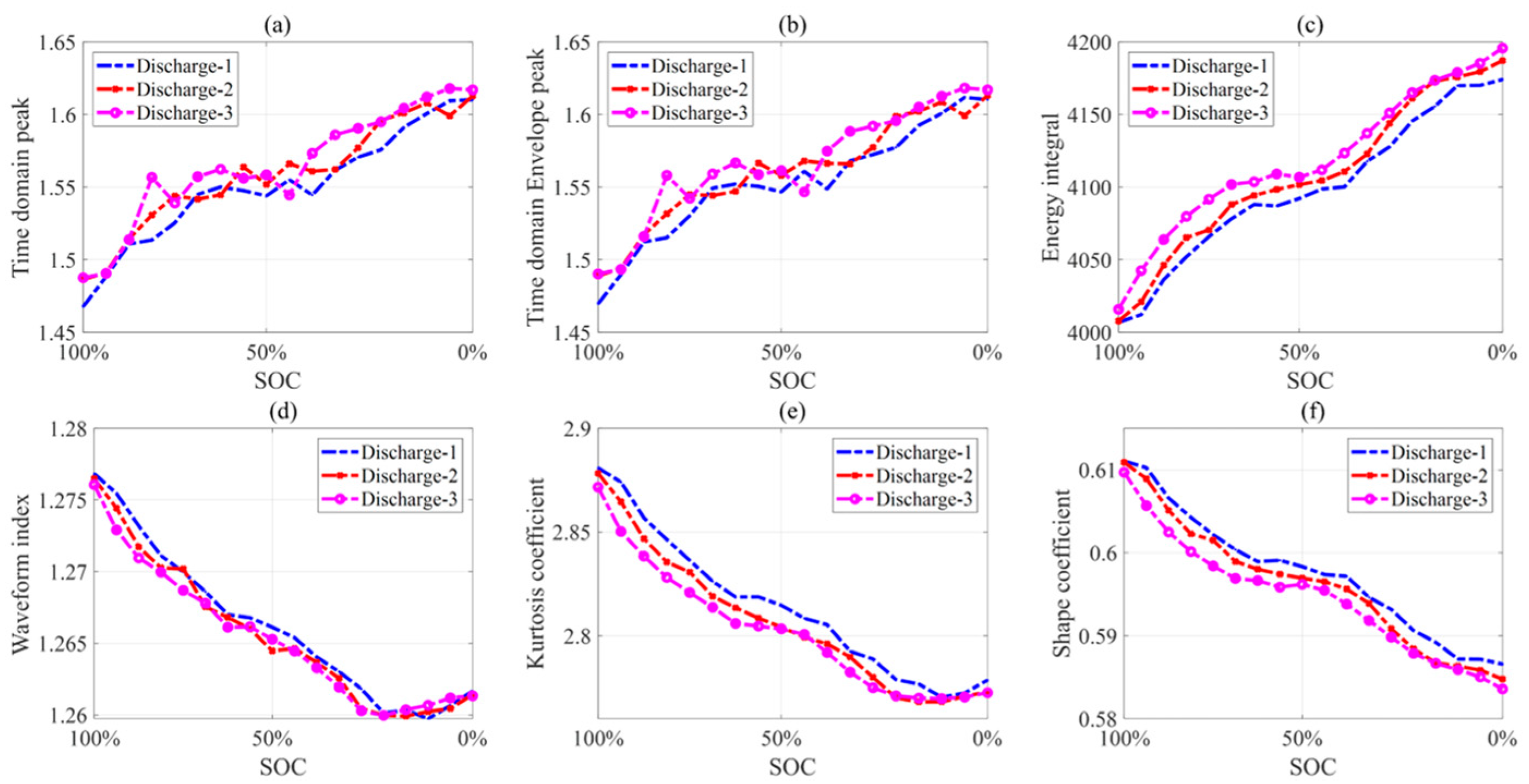
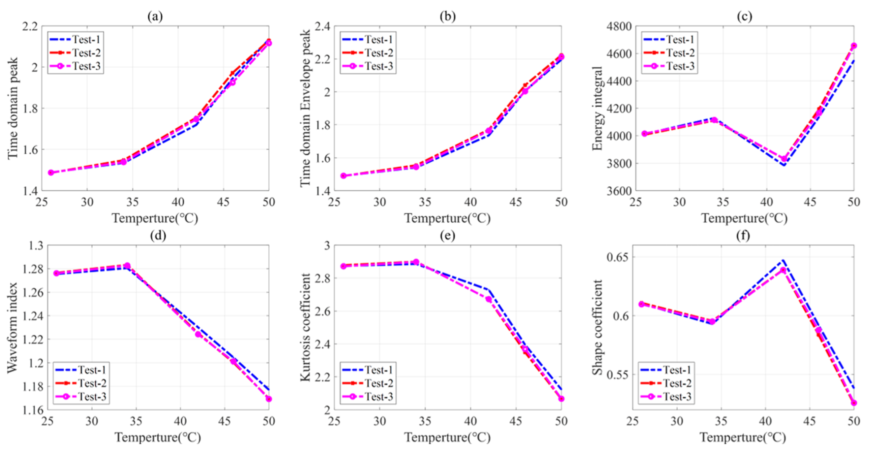
5.1. Influence of Battery States on the Ultrasonic Signal

According to the analysis in Section 2.2, the change in SOC can cause internal structural changes in the battery, which can affect the ultrasonic reflection waves. As shown in Figure 8a, two wave parts are obtained in the CC discharge mode. In part 1, the signal amplitude changes with the battery’s SOC (Figure 8b). When the battery’s SOC is high, the amplitude of the signal envelope is low. The amplitude of the signal envelope gradually increases when the battery’s SOC decreases (Figure 8c). In Figure 8d, the signal amplitude not only changes in a small range but also moves forward and backward in phase with the change in the battery’s SOC. When the battery’s SOC is high, the phase of the ultrasonic signal moves forward, and the signal amplitude is high. When the battery’s SOC decreases, the phase of the ultrasonic signal moves backward, and the signal amplitude gradually decreases, as shown in Figure 8e.
The increase in temperature can reduce the electrolyte density inside the battery, leading to an increase in ultrasonic velocity. The decrease in electrolyte density also causes a decrease in the scattering attenuation coefficient, leading to an increase in the amplitude of the reflected wave. As shown in Figure 9a, two wave parts are also obtained at different discharge temperatures; the wave parts move to the left and upwards with increasing battery temperature. As shown in Figure 9b, when the temperature is 26 °C, the phase of part 1 is backward, and its amplitude is low. When the temperature of the battery continues to rise, the envelope of part 1 shifts to the left and increases significantly (Figure 9c). The phase of part 2 also moves to the left, and its amplitude gradually increases (Figure 9d). The amplitude of envelope part 2 changes more obviously (Figure 9e).

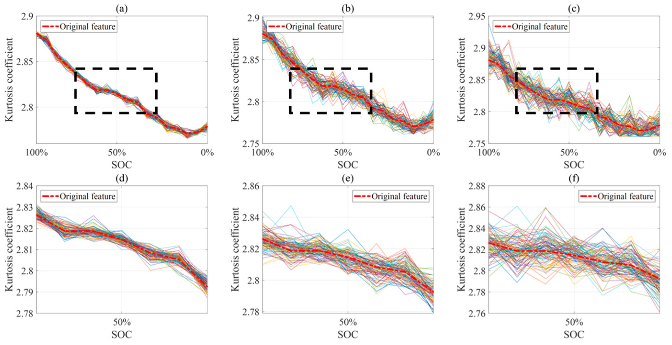
5.2. Optimal Ultrasonic Signal Application Range

Figure 10 shows the variation of six feature indicators with the battery’s SOC during the optimal extraction interval of ultrasonic reflection waves. In the CC discharge mode, each feature indicator changes obviously. The feature indicators are consistent with the changes in the ultrasonic waves with the battery’s SOC. With the decrease in the battery’s SOC, the attenuation degree of the ultrasonic waves decreases, resulting in a gradual increase in the SA. As a result, the time domain feature indicators—such as the time domain peak, the time domain envelope peak, and the energy integral—increase. However, the waveform index, kurtosis coefficient, and shape coefficient gradually decrease with increasing battery SOC.
The variations of the six feature indicators with the battery’s temperature are shown in Figure 11. When the temperature is increased from 26 °C to 50 °C, the time domain peak, time domain envelope peak, and energy integration increase with increasing battery temperature. The waveform index, kurtosis coefficient, and shape coefficient decrease with increasing battery temperature. When the battery temperature is between 26 °C and 34 °C, the characteristic parameters do not change significantly, due to the small changes in the density and viscosity of the electrolyte inside the battery. However, as the temperature increases from 34 °C to 50 °C, the characteristic parameters undergo significant changes. In addition, it can also be seen that the feature indicator changes have a high degree of consistency in multiple discharge cycles.

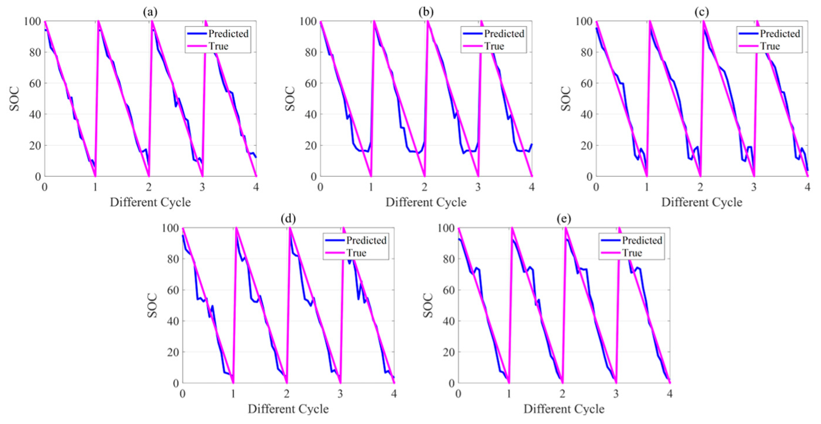
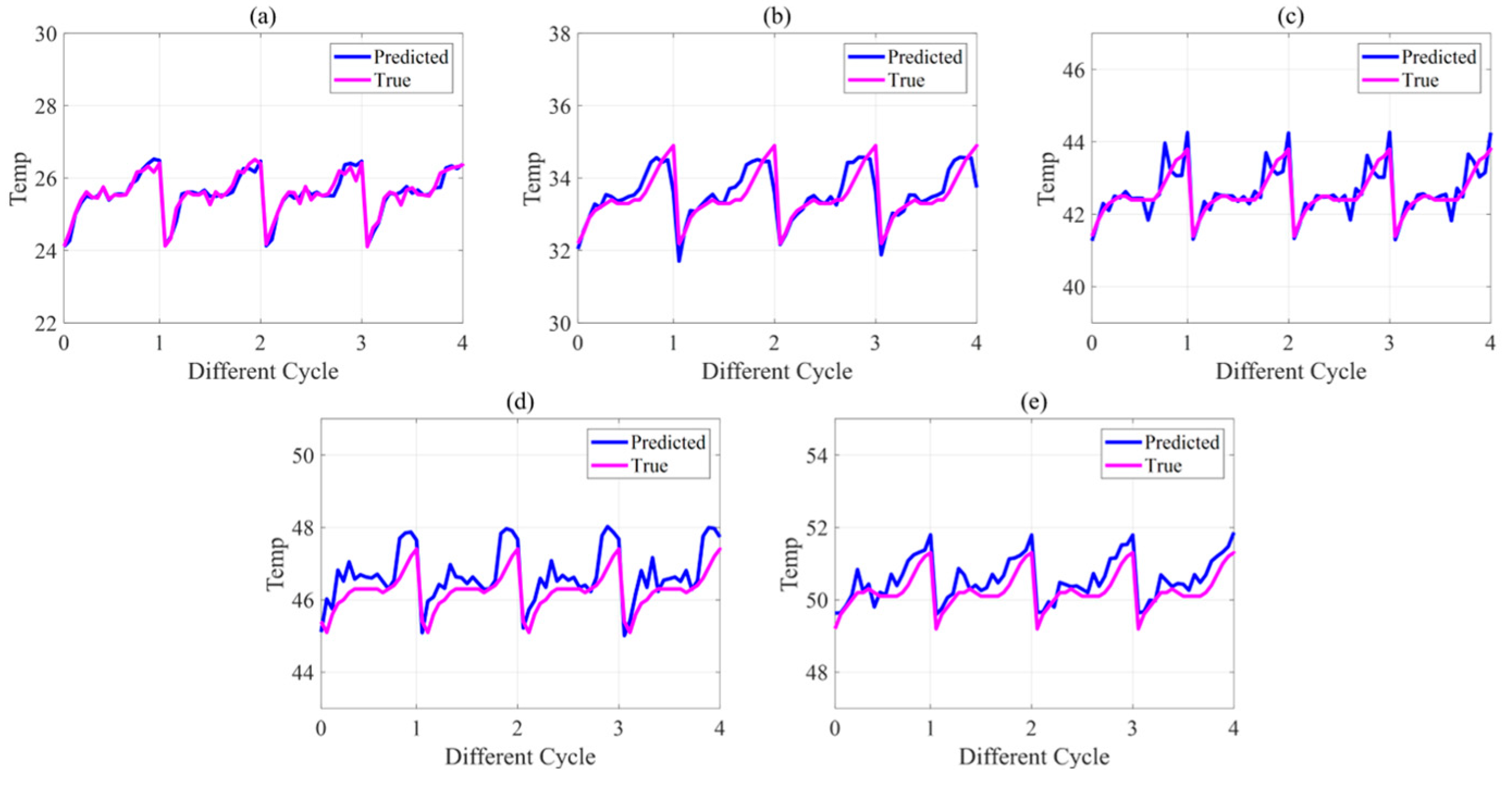
5.3. Battery State Estimation Results

To conduct a quantitative evaluation of the prediction results, RMSE was utilized to describe the error between the true value and the predicted value. The expression of RMSE is given by Equation (16):
R M S E = 1 N i = 1 N ( Q i Q ^ i ) 2
where Qi represents the predicted value, Q ^ i represents the true value, and N represents the number of values.
In order to evaluate the method proposed in this paper, the estimated results of battery SOC under different temperature environments were analyzed, as shown in Figure 12. Four battery discharge cycles were performed for each temperature condition. It can be seen that the estimated SOC of the battery can match the true value. However, when the battery’s temperature is 46 °C or 50 °C and the SOC is 60%, there is a significant change in the feature indicators, resulting in an error in battery SOC estimation. The RMSE of the battery SOC estimation result over a wide temperature range is 7.42%.
The estimated results of battery temperature under different temperature environments are presented in Figure 13. Four discharge cycles were performed on the battery under each temperature condition. The battery temperature estimation results obtained by the method are consistent with the true value. The RMSE of the estimation result of battery temperature over a wide temperature range is 0.4 °C.
In order to further verify the effectiveness of the method proposed in this paper, three groups of methods were applied. In Group 1, the original ultrasonic signal data were directly input into the BP neural network model for training. The output label was set to battery SOC. In Group 2, the output labels were set to battery SOC and battery temperature. In Group 3, the dataset was expanded by virtual sample generation. The BP neural network model was used for battery state estimation. The output labels were set to battery SOC and temperature. The RMSE was used to evaluate the performance of the algorithm. The results are shown in Table 6.
Comparing Group 1 with Group 2, it can be found that the BP neural network model did not significantly reduce the estimation accuracy of SOC and temperature simultaneously. The comparison between Group 2 and Group 3 indicates that the estimation accuracy of SOC and temperature can be improved by using virtual samples to expand the original data.

5.4. Discussion

This study proposes a method to estimate battery states based on ultrasonic reflection waves. The influence of SOC and temperature on the ultrasonic reflection wave of the battery was considered. To gain a deeper understanding of the internal structure of the battery as its state changes, sliding windows were used to analyze the optimal interval of feature extraction, so that the extracted features would have a better correlation with the battery state and enhance the robustness of the model. Because battery charging and discharging are relatively time–consuming, the data available for model training were limited. The MD-MTD algorithm was used to generate virtual samples and increase the number of charge and discharge cycles to increase the training data of the model. The proposed method was validated under specific experimental conditions in CC discharge mode. However, in practice, the operating conditions of the battery may be uncertain due to varying environments, which can negatively impact the accuracy of the model.
The results illustrate that the proposed method can achieve a satisfactory level of accuracy in estimating the states of the battery. In the future, to better measure the lithium content in the anode or cathode during the process of a lithium iron phosphate battery’s SOC and temperature changes, ICP-OES experiments could be employed for further investigations.

6. Conclusions

In this paper, a joint estimation method for battery SOC and temperature based on ultrasonic reflection waves is proposed. Only one piezoelectric transducer is used for two–state estimation. The feature indicator extraction intervals of the ultrasonic signal are determined by sliding–window matching correlation analysis. Virtual samples are used to expand the data after feature extraction. The sample size for model training can be improved. In the battery modeling process, a BP neural network model is applied to estimate the battery states. The model demonstrates a high level of accuracy in state estimation. The proposed method was verified by battery experiments. The RMSE of the battery SOC and battery temperature estimation results was 7.42% and 0.40 °C, respectively. Additionally, the method is nondestructive and easy to apply in battery management systems. This research provides a new approach to nondestructively evaluate battery states.
The transmission of ultrasonic reflection waves in different batteries is inconsistent, due to variations in the manufacturing processes employed for each battery. When estimating the state of various batteries, it might be necessary to assess the disparity between the batteries beforehand and make appropriate adjustments to the model. This paper has not introduced the prediction of gas production inside the battery, which is a valuable area for future exploration.

Author Contributions

Conceptualization, R.Z. and X.L.; methodology, X.L.; software, R.Z.; validation, R.Z. and X.L.; formal analysis, X.L. and R.Z.; investigation, X.L. and C.S.; resources, X.L., Y.T. and J.T.; data curation, R.Z. and S.Y.; writing—original draft preparation, R.Z. and X.L.; writing—review and editing, X.L., C.S. and Y.T.; visualization, R.Z., S.Y. and X.L.; supervision, X.L. and J.T.; project administration, X.L. and J.T.; funding acquisition, X.L. All authors have read and agreed to the published version of the manuscript.

Funding

This work was supported by the Natural Science Foundation of Guangdong Province (2021A1515010525), the National Natural Science Foundation of China (No. 52177219), and the Natural Science Foundation of Shenzhen (University Stability Support Program No. 20220807222119001).

Data Availability Statement

Not applicable.

Conflicts of Interest

The authors declare no conflict of interest. The funders had no role in the design of the study; in the collection, analyses or interpretation of data; in the writing of the manuscript; or in the decision to publish the results.

References

  1. Sun, F. Green Energy and Intelligent Transportation—Promoting Green and Intelligent Mobility. Green Energy Intell. Transp. 2022, 1, 100017. [Google Scholar] [CrossRef]
  2. Xiong, R.; Kim, J.; Shen, W.; Lv, C.; Li, H.; Zhu, X.; Zhao, W.; Gao, B.; Guo, H.; Zhang, C.; et al. Key Technologies for Electric Vehicles. Green Energy Intell. Transp. 2022, 1, 100041. [Google Scholar] [CrossRef]
  3. Sparber, W.; Grotto, A.; Zambelli, P.; Vaccaro, R.; Zubaryeva, A. Evaluation of Different Scenarios to Switch the Whole Regional Bus Fleet of an Italian Alpine Region to Zero-Emission Buses. World Electr. Veh. J. 2023, 14, 91. [Google Scholar] [CrossRef]
  4. Fahim, K.E.; De Silva, L.C.; Hussain, F.; Shezan, S.K.A.; Yassin, H. An Evaluation of ASEAN Renewable Energy Path to Carbon Neutrality. Sustainability 2023, 15, 6961. [Google Scholar] [CrossRef]
  5. Song, K.; Lan, Y.; Zhang, X.; Jiang, J.; Sun, C.; Yang, G.; Yang, F.; Lan, H. A Review on Interoperability of Wireless Charging Systems for Electric Vehicles. Energies 2023, 16, 1653. [Google Scholar] [CrossRef]
  6. Zhao, H.; Guo, S.; Zhao, H. Comprehensive Performance Assessment on Various Battery Energy Storage Systems. Energies 2018, 11, 2841. [Google Scholar] [CrossRef] [Green Version]
  7. Lyu, P.; Liu, X.; Qu, J.; Zhao, J.; Huo, Y.; Qu, Z.; Rao, Z. Recent Advances of Thermal Safety of Lithium Ion Battery for Energy Storage. Energy Storage Mater. 2020, 31, 195–220. [Google Scholar] [CrossRef]
  8. Fioravanti, R.; Kumar, K.; Nakata, S.; Chalamala, B.; Preger, Y. Predictive-Maintenance Practices: For Operational Safety of Battery Energy Storage Systems. IEEE Power Energy Mag. 2020, 18, 86–97. [Google Scholar] [CrossRef]
  9. Zhang, Y.; Jiang, M.; Zhou, Y.; Zhao, S.; Yuan, Y. Towards High-Safety Lithium-Ion Battery Diagnosis Methods. Batteries 2023, 9, 63. [Google Scholar] [CrossRef]
  10. Li, X.; Huang, Z.; Hua, W.; Rao, L.; Tian, Y.; Tian, J. Mechanical Vibration Modeling and Characterization of a Plastic-Cased Lithium-Ion Battery. Green Energy Intell. Transp. 2022, 1, 100006. [Google Scholar] [CrossRef]
  11. Zappen, H.; Fuchs, G.; Gitis, A.; Sauer, D. In-Operando Impedance Spectroscopy and Ultrasonic Measurements during High-Temperature Abuse Experiments on Lithium-Ion Batteries. Batteries 2020, 6, 25. [Google Scholar] [CrossRef] [Green Version]
  12. Xu, J.; Sun, C.; Ni, Y.; Lyu, C.; Wu, C.; Zhang, H.; Yang, Q.; Feng, F. Fast Identification of Micro-Health Parameters for Retired Batteries Based on a Simplified P2D Model by Using Padé Approximation. Batteries 2023, 9, 64. [Google Scholar] [CrossRef]
  13. Zhou, M.; Wei, K.; Wu, X.; Weng, L.; Su, H.; Wang, D.; Zhang, Y.; Li, J. Fractional-Order Sliding-Mode Observers for the Estimation of State-of-Charge and State-of-Health of Lithium Batteries. Batteries 2023, 9, 213. [Google Scholar] [CrossRef]
  14. Yang, X.; Ma, B.; Xie, H.; Wang, W.; Zou, B.; Liang, F.; Hua, X.; Liu, X.; Chen, S. Lithium-Ion Battery State of Health Estimation with Multi-Feature Collaborative Analysis and Deep Learning Method. Batteries 2023, 9, 120. [Google Scholar] [CrossRef]
  15. Li, Z.; Shen, S.; Zhou, Z.; Cai, Z.; Gu, W.; Zhang, F. Novel Method for Modelling and Adaptive Estimation for SOC and SOH of Lithium-Ion Batteries. J. Energy Storage 2023, 62, 106927. [Google Scholar] [CrossRef]
  16. Jasiūnienė, E.; Mažeika, L.; Samaitis, V.; Cicėnas, V.; Mattsson, D. Ultrasonic Non-Destructive Testing of Complex Titanium/Carbon Fibre Composite Joints. Ultrasonics 2019, 95, 13–21. [Google Scholar] [CrossRef] [PubMed]
  17. Hu, S.; Shi, W.; Lu, C.; Chen, Y.; Chen, G.; Shen, G. Rapid Detection of Cracks in the Rail Foot by Ultrasonic B-Scan Imaging Using a Shear Horizontal Guided Wave Electromagnetic Acoustic Transducer. NDT E Int. 2021, 120, 102437. [Google Scholar] [CrossRef]
  18. Ying, K.-N.; Ni, C.-Y.; Dai, L.-N.; Yuan, L.; Kan, W.-W.; Shen, Z.-H. Multi-Mode Laser-Ultrasound Imaging Using Time-Domain Synthetic Aperture Focusing Technique (T-SAFT). Photoacoustics 2022, 27, 100370. [Google Scholar] [CrossRef]
  19. Sood, M.B.; Osterman, M.; Pecht, M. Health monitoring of lithium-ion batteries. In Proceedings of the 2013 IEEE Symposium on Product Compliance Engineering (ISPCE), Austin, TX, USA, 7–9 October 2013; pp. 1–6. [Google Scholar] [CrossRef]
  20. Hsieh, A.G.; Bhadra, S.; Hertzberg, B.J.; Gjeltema, P.J.; Goy, A.; Fleischer, J.W.; Steingart, D.A. Electrochemical-Acoustic Time of Flight: In Operando Correlation of Physical Dynamics with Battery Charge and Health. Energy Environ. Sci. 2015, 8, 1569–1577. [Google Scholar] [CrossRef]
  21. Gold, L.; Bach, T.; Virsik, W.; Schmitt, A.; Müller, J.; Staab, T.E.M.; Sextl, G. Probing Lithium-Ion Batteries’ State-of-Charge Using Ultrasonic Transmission—Concept and Laboratory Testing. J. Power Sources 2017, 343, 536–544. [Google Scholar] [CrossRef]
  22. Ladpli, P.; Kopsaftopoulos, F.; Chang, F.-K. Estimating State of Charge and Health of Lithium-Ion Batteries with Guided Waves Using Built-in Piezoelectric Sensors/Actuators. J. Power Sources 2018, 384, 342–354. [Google Scholar] [CrossRef]
  23. Copley, R.J.; Cumming, D.; Wu, Y.; Dwyer-Joyce, R.S. Measurements and Modelling of the Response of an Ultrasonic Pulse to a Lithium-Ion Battery as a Precursor for State of Charge Estimation. J. Energy Storage 2021, 36, 102406. [Google Scholar] [CrossRef]
  24. Zhao, G.; Liu, Y.; Liu, G.; Jiang, S.; Hao, W. State-of-Charge and State-of-Health Estimation for Lithium-Ion Battery Using the Direct Wave Signals of Guided Wave. J. Energy Storage 2021, 39, 102657. [Google Scholar] [CrossRef]
  25. Sun, H.; Muralidharan, N.; Amin, R.; Rathod, V.; Ramuhalli, P.; Belharouak, I. Ultrasonic Nondestructive Diagnosis of Lithium-Ion Batteries with Multiple Frequencies. J. Power Sources 2022, 549, 232091. [Google Scholar] [CrossRef]
  26. Galiounas, E.; Tranter, T.G.; Owen, R.E.; Robinson, J.B.; Shearing, P.R.; Brett, D.J.L. Battery State-of-Charge Estimation Using Machine Learning Analysis of Ultrasonic Signatures. Energy AI 2022, 10, 100188. [Google Scholar] [CrossRef]
  27. Li, X.; Hua, W.; Wu, C.; Zheng, S.; Tian, Y.; Tian, J. State Estimation of a Lithium-Ion Battery Based on Multi-Feature Indicators of Ultrasonic Guided Waves. J. Energy Storage 2022, 56, 106113. [Google Scholar] [CrossRef]
  28. Schmerr, L.W. Fundamentals of Ultrasonic Nondestructive Evaluation: A Modeling Approach; Springer Series in Measurement Science and Technology; Springer International Publishing: Cham, Switzerland, 2016; ISBN 978-3-319-30461-8. [Google Scholar]
  29. Feng, Y. Research on Casing Detection in Mixed Media Based on Ultrasonic Wave; Harbin Institute of Technology: Harbin, China, 2013. [Google Scholar]
  30. Zhang, Q. Study on Attenuation Characteristics of Ultrasonic Propagation in Non-Uniform Medium; Shenyang University of Technology: Shenyang, China, 2015. [Google Scholar]
  31. Swallow, J.G.; Woodford, W.H.; McGrogan, F.P.; Ferralis, N.; Chiang, Y.-M.; Van Vliet, K.J. Effect of Electrochemical Charging on Elastoplastic Properties and Fracture Toughness of LiXCoO2. J. Electrochem. Soc. 2014, 161, F3084–F3090. [Google Scholar] [CrossRef]
  32. Meng, X.; Zheng, P.; Wu, J. Experimental measurement of viscosity and density of dimethyl carbonate. J. Engi-Neering Thermophys. 2009, 30, 26–30. [Google Scholar]
  33. Li, D.-C.; Wu, C.-S.; Tsai, T.-I.; Lina, Y.-S. Using Mega-Trend-Diffusion and Artificial Samples in Small Data Set Learning for Early Flexible Manufacturing System Scheduling Knowledge. Comput. Oper. Res. 2007, 34, 966–982. [Google Scholar] [CrossRef]
  34. Tian, Y.; Dong, Q.; Tian, J.; Li, X.; Li, G.; Mehran, K. Capacity Estimation of Lithium-Ion Batteries Based on Optimized Charging Voltage Section and Virtual Sample Generation. Appl. Energy 2023, 332, 120516. [Google Scholar] [CrossRef]
  35. Jin, D.; Lin, S. (Eds.) Advances in Computer Science and Information Engineering: Volume 2; Advances in Intelligent and Soft Computing; Springer: Berlin/Heidelberg, Germany, 2012; Volume 169, ISBN 978-3-642-30222-0. [Google Scholar]
Figure 1. The reflected ultrasonic wave.
Batteries 09 00335 g001
Figure 2. Schematic diagram of the sliding–window.
Batteries 09 00335 g002
Figure 3. Virtual samples generated by different fit values: (a,d) fit value are set to 0.001; (b,e) fit value are set to 0.003; (c,f) fit value are set to 0.006.
Batteries 09 00335 g003
Figure 4. The framework of the battery state estimation.
Batteries 09 00335 g004
Figure 5. The layout of the sensors in the battery experiment.
Batteries 09 00335 g005
Figure 6. Schematic diagram of the experimental battery system.
Batteries 09 00335 g006
Figure 7. Battery charge–discharge profile of the experiment: (a) voltage; (b) current; (c) SOC.
Batteries 09 00335 g007
Figure 8. Changes in the ultrasonic reflection wave during battery CC discharge mode: (a) Ultrasonic reflection waves; (b) Part 1 of ultrasonic reflection waves; (c) Amplitude change of ultrasonic part 1 envelope; (d) Part 2 of ultrasonic reflection waves; (e) Phase change of ultrasonic part 2.
Batteries 09 00335 g008
Figure 9. Changes in the ultrasonic reflection wave of the battery at three (minimum, intermediate, maximum) different temperatures: (a) Ultrasound reflection waves; (b) Part 1 of ultrasonic reflection waves; (c) Amplitude change of ultrasonic part 1 envelope; (d) Part 2 of ultrasonic reflection waves; (e) Amplitude change of ultrasonic part 2 envelope.
Batteries 09 00335 g009
Figure 10. The features in the optimal correlation interval vary with the battery’s SOC: (a) Time domain peak; (b) Time domain envelope peak; (c) Energy integral; (d) Waveform index; (e) Kurtosis coefficient; (f) Shape coefficient.
Batteries 09 00335 g010
Figure 11. The features in the optimal correlation interval vary with battery temperature: (a) Time domain peak; (b) Time domain envelope peak; (c) Energy integral; (d) Waveform index; (e) Kurtosis coefficient; (f) Shape coefficient.
Batteries 09 00335 g011
Figure 12. Predicted SOC of batteries in different temperature environments: (a) 26 °C; (b) 34 °C; (c) 42 °C; (d) 46 °C; (e) 50 °C.
Batteries 09 00335 g012
Figure 13. Prediction of battery temperature in different temperature environments: (a) 26 °C; (b) 34 °C; (c) 42 °C; (d) 46 °C; (e) 50 °C.
Batteries 09 00335 g013
Table 1. Effects of temperature and pressure on the density of DMC.
Pressure\TemperatureDensity ρ (kg·m3)
20 °C30 °C40 °C50 °C
0.1 MPa1068.601054.901041.481029.87
4.56 MPa1072.271059.301045.901032.93
9.58 MPa1077.091064.351050.351038.48
Table 2. Effects of temperature and pressure on the viscosity of DMC.
Pressure\TemperatureViscosity η (mPa·s)
20 °C30 °C40 °C50 °C
0.1 MPa0.6190.5470.4910.438
4.56 MPa0.6370.5610.5030.448
9.58 MPa0.6590.5810.5130.463
Table 3. Feature indicators for ultrasonic signal analysis.
IndicatorEquationImplication
Time domain peak P t = max ( A ) Maximum amplitude of time domain waveform
Time domain envelope peak P e t = max ( e n v e l o p e ( A ) ) Maximum amplitude of time domain waveform envelope
Energy integral E = a b A 2 d t Energy of the signal time domain waveform
Waveform index W = 1 N i = 1 N A i 2 1 N i = 1 N | A i | Degree of fluctuation of the signal time domain waveform
Kurtosis coefficient K = 1 N i = 1 N A i 4 ( 1 N i = 1 N A i 2 ) 4 Sharpness of the peak of the signal time domain waveform
Shape coefficient S = L i = 1 N A i 2 Distribution range of the signal time domain waveform on the time axis
Table 4. Correlation in different intervals.
IndicatorOptimal
Interval
Optimal Interval
Correlation
Part 1
Correlation
Part 2
Correlation
Time domain peak (Pt)1750:3500−0.95−0.950.56
Time domain envelope peak (Pet)1750:3500−0.95−0.950.56
Energy integral (E)1050:3500−0.99−0.990.38
Waveform index (W)1050:27500.930.630.86
Kurtosis coefficient (K)1050:27500.980.770.82
Shape coefficient (S)1050:35000.990.99−0.38
Table 5. Parameters of the BP neural network model.
ParametersValue
Layers6
Input shape6
Output shape2
Epochs300
Batch size256
Table 6. Prediction errors of battery SOC and battery temperature in three control groups.
Group 1
RMSE26 °C34 °C42 °C46 °C50 °C
SOC (%)8.606.507.5310.2210.04
TEMP (°C)/////
Group 2
RMSE26 °C34 °C42 °C46 °C50 °C
SOC (%)7.746.589.639.2511.98
TEMP (°C)0.800.831.081.260.94
Group 3
RMSE26 °C34 °C42 °C46 °C50 °C
SOC (%)6.119.206.897.806.76
TEMP (°C)0.290.400.310.560.38
Disclaimer/Publisher’s Note: The statements, opinions and data contained in all publications are solely those of the individual author(s) and contributor(s) and not of MDPI and/or the editor(s). MDPI and/or the editor(s) disclaim responsibility for any injury to people or property resulting from any ideas, methods, instructions or products referred to in the content.

