Article

Mediating Lithium Plating/Stripping by Constructing 3D Au@Cu Pentagonal Pyramid Array

1
Department of Agricultural and Biosystems Engineering, South Dakota State University, Brookings, SD 57007, USA
2
Department of Electrical Engineering and Computer Science, South Dakota State University, Brookings, SD 57007, USA
3
Department of Chemistry, Biology, and Health Sciences, South Dakota School of Mines and Technology, Rapid City, SD 57701, USA
*
Authors to whom correspondence should be addressed.
Batteries 2023, 9(5), 279; https://doi.org/10.3390/batteries9050279
Submission received: 23 March 2023 / Revised: 12 May 2023 / Accepted: 17 May 2023 / Published: 19 May 2023
(This article belongs to the Special Issue Recent Advances in Lithium Metal Batteries and Beyond)

Abstract

:
Lithium (Li) metal is perceived as the “holy grail” of anodes for secondary batteries due to its innate merits. Regrettably, the commercial application of Li metal anodes (LMAs) has been hampered by problems derived from the uncontrollable growth of Li dendrites, which could result in formation of short-circuits, thereby leading to fatal safety accidents. Here, a three-dimensional lithiophilic gold (Au)-coated copper (Cu) pentagonal pyramid array (Au@CuPPA) is constructed on planar Cu foil via electrodeposition followed by a chemical reduction method. Owing to the features of the lithiophilic layer and 3D porous structure, the proposed Au@CuPPA can not only facilitate Li-ion migration and charge transfer, but also effectively diminish the nucleation overpotential. Consequently, an even and steady Li plating/stripping process for up to 460 h and with a charge capacity of 3 mAh cm−2 is accomplished by using the Au@CuPPA current collector. The Li@Au@CuPPA|LiFePO4 full cell achieves a high Coulombic efficiency (CE) of 99.4% for 150 cycles at 0.5 C with a capacity retention of 92.4%.

1. Introduction

Commercial Li-ion batteries utilizing layered graphite as the anode cannot satisfy increasing energy density requirements for expanding industries focused on energy storage [1,2,3,4,5]. Lithium metal is recognized as a highly anticipated anode candidate due to its inherent properties, such as its ultrahigh specific capacity of 3860 mAh g−1 and extremely low electrode potential of −3.04 V [6,7,8,9,10,11]. These intriguing merits define Li metal as an indispensable component for Li-Sulfur, Li-Air, and Li-Selenium battery systems [12,13,14]. However, its persistent impediment to extensive applications is the existence of uncontrollable growth of lithium dendrites during continuous reversible reaction processes, which triggers inhomogeneous Li deposition, decreased stability of solid electrolyte interphase (SEI) film, puncture of the separator, and eventual cell malfunction [15,16,17,18].
To solve these challenges, many approaches, including novel liquid electrolyte additives [19,20], artificial SEI films [21,22], and new separators [23,24], were used to deter the growth of lithium dendrites and stabilize the interfacial reaction of the electrodes. However, these strategies cannot provide the structural host for Li deposition, and the challenge of the lithium metal’s boundless volume change is still ubiquitous. Alternatively, employing a porous, structured current collector with a large specific surface area-conductive skeleton has been deemed as an effective and simple method to regulate the volume expansion of Li and confine the dendrite growth [25,26]. Numerous modified Cu-based current collectors, such as the 3D Cu skeleton with hierarchically structured bi-continuous porosity [27,28], 3D porous copper [29,30,31], or copper mesh [32,33], were exploited for Li metal anode applications. Unfortunately, Li metal cannot be incorporated into these current collectors due to the weak adhesion of lithium to copper [34,35,36]. Particularly, under a high current density, the further Li deposition merely takes place on the upper area of the 3D Cu current collector, causing underutilization of the porous skeleton [30,37,38]. As a result, it is imperative to design a 3D porous Li host with a lithiophilic interface to solve these challenges.
Herein, we synthesized a high surface area copper substrate with a pyramidal architecture which was functionalized by an Au layer (Au@CuPPA) for Li metal anodes by employing the facile electrodeposition and chemical reduction method. In comparison with a planar Cu foil current collector, nano-pyramids of Au@CuPPA are interleaved and stacked to constitute 3D porous structures, which increases the surface area and minimizes lithium dendrite growth. More importantly, the lithiophilic Au layer on the surface of Au@CuPPA can provide diffusion channels for the Li metal that travel to the bottom of the 3D structure, thereby providing an adequate utilization of the nanoporous structure. Owing to these properties, Au@CuPPA-based electrodes exhibit extremely low overpotential, superior Coulombic efficiency (CE), and durable cycling stability for up to 460 h. In addition, the Li@Au@CuPPA-based full cell demonstrates high cycling stability and rate properties.

2. Materials and Methods

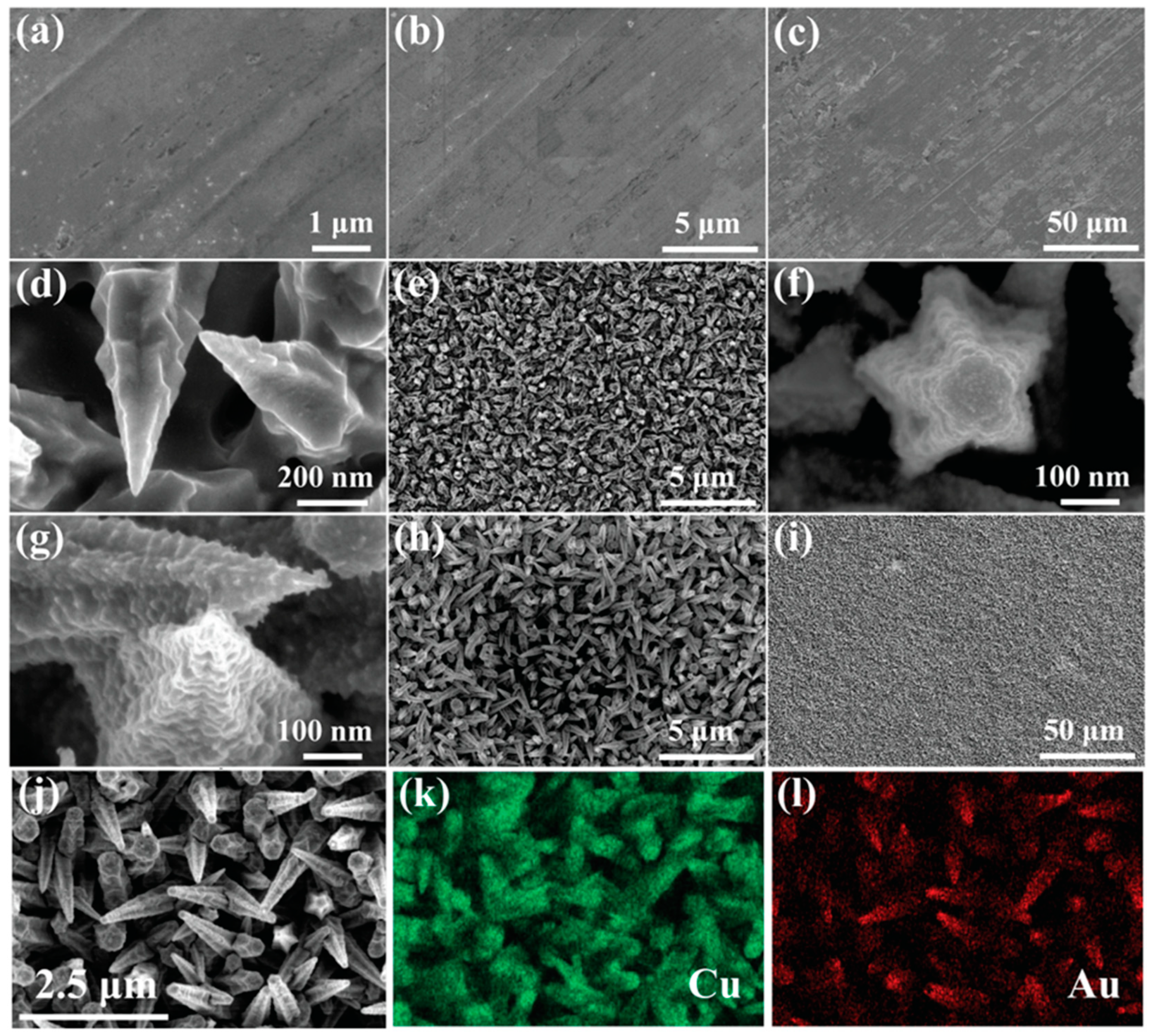
2.1. Synthesis of Au@Cu Pentagonal Pyramid Array/Cu Foil

The copper foils were sequentially immersed in acetone, ethanol, 0.8 M H2SO4, and deionized water, with ultrasonic bath treatment for 20 min, and then dried in a vacuum for 30 min at 60 °C. The Copper Pyramid Array (CuPA) was prepared in a three-electrode setup using the platinum-coated titanium mesh as the counter electrode, saturated calomel electrode as the reference electrode, and the pretreated Cu foil as the working electrode (surface area of 1 cm2) soaked in the electroplating solution consisting of CuSO4·5H2O (26 mM), NiSO4·6H2O (2 mM), NaH2PO2·H2O (200 mM), Na3C6H5O7·2H2O (30 mM), and polyethylene glycol (8 mg L−1). Potentiostatic electrodeposition was implemented at −1.00 V for 10 min by utilizing the electrochemical instrumentation (CHI760E, CH Instruments, Inc. Austin, TX, USA). Subsequently, 1.5 mg mL−1 of HAuCl4 solution and a 200 mM NaBH4 solution were prepared via the magnetic stirring method for 15 min. Then, CuPA was immersed into the HAuCl4 solution with magnetic stirring for 5 min. After that, the NaBH4 solution was added dropwise to the above solution within 1 min after magnetic stirring for 30 min. Lastly, the as-prepared samples denoted as Au@CuPPA were washed with deionized water and dried in a vacuum environment for 30 min at 60 °C.

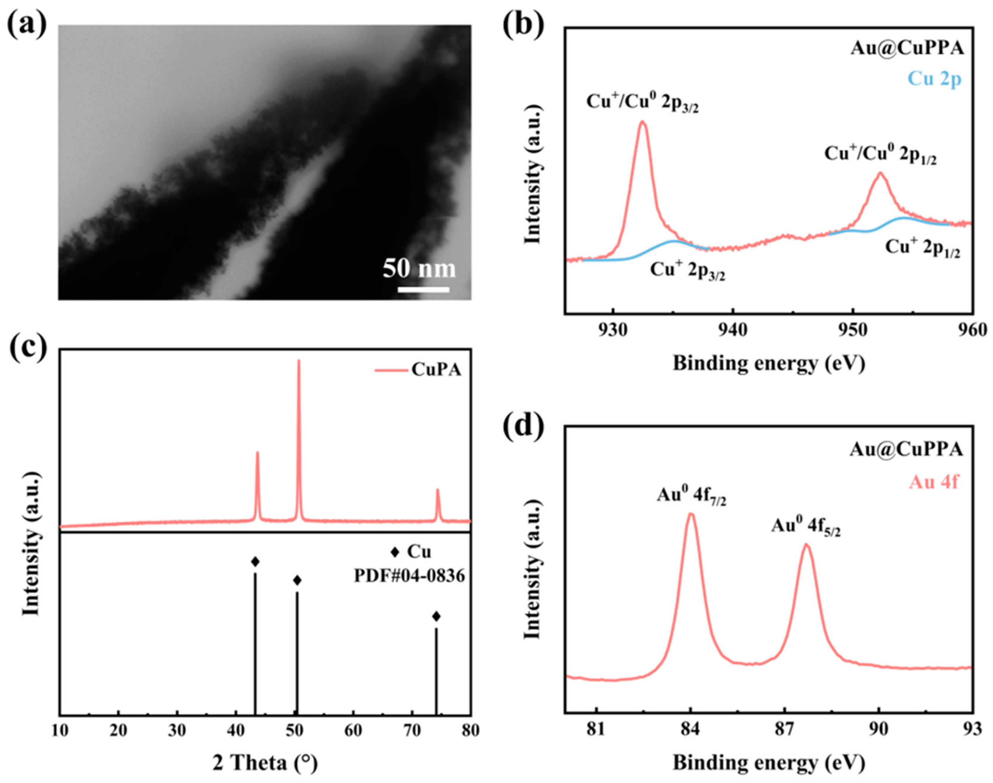
2.2. Material Characterization

The scanning electron microscopy (Thermo Scientific™ Helios™ 5 CX Dual Beam field emission system with STEM-in-SEM and a full Oxford AZtec EDS, Waltham, MA, USA) was used to capture the SEM, STEM images, and EDX elemental mapping results of pristine Cu foil, CuPA, and Au@CuPPA. The X-ray diffractometer (Rigaku Ultima-Plus, Tokyo, Japan) and the X-ray Photoelectron Spectrometer (Thermo Scientific K-alpha+, Waltham, MA, USA) were used to identify the composition information of the samples. Scanning electron microscopy (FESEM, Hitachi, S-4700, Tokyo, Japan) was utilized to characterize the morphological evolution of lithium metal deposition.

2.3. Electrochemical Measurements

The CR2032-type coin cells were fabricated in an argon glovebox. Coulombic efficiency measurements and long-term Li plating and stripping evaluation under different current densities and capacity were conducted by employing a NEWARE battery-testing system at 25 °C. Lithium iron phosphaete (LiFePO4) with a mass load of 3 mg cm−2 was adopted as the cathode material for the evaluation of the full cells. A certain amount of lithium metal (3 mAh cm−2) was pre-deposited on the Au@CuPPA substrates before assembling the full cell. The Electrochemical Impedance Spectroscopy (EIS) measurement with a frequency range of 100 kHz–10 mHz and an amplitude of 5 mV was performed using a CHI760E electrochemical instrument.

3. Results

Figure 1a–c displays SEM images of the planar Cu foil at different magnifications. A relatively smooth and flat surface of Cu foil was observed. Figure 1d,e shows SEM images of CuPA electrodeposited on pristine Cu foil. The individual CuPA substrate possesses a nano-pyramid structure. These Cu pyramid arrays are stacked to generate a 3D porous structure, which leads to a larger specific surface area compared to the planar Cu foil substrate. Figure 1f–i demonstrates that Au@CuPPA architecture has a pentagonal pyramidal shape and is surface-modified by gold Au. Meanwhile, the 3D porous structure owned by Au@CuPPA could sterically retard the growth of Li dendrites. Additionally, the pentagonal pyramid structure expands the specific surface area of the substrates and diminishes the local current density of the electrodes during the Li reaction process. Figure 1j–l illustrates the EDS elemental mapping of Au@CuPPA, indicating the existence and even distribution of the elements Au and Cu.
The STEM image (Figure 2a) demonstrates a uniform and dense distribution of the Au layer on the surface of the Cu array. Figure 2c displays the XRD profiles of CuPA. The three typical peaks of CuPA at 43.36, 50.32, and 74.04°, respectively [39,40]. These three typical peaks are completely aligned with the (111), (200), and (220) lattice planes of Cu (PDF, No. 04-0836), which proves that CuPA is perfectly composed of Cu element. The Cu 2p XPS spectrum of Au@CuPPA (Figure 2b) indicates the presence of Cu2+ (935.02 and 954.01 eV) and Cu0/Cu+ (932.38 and 952.08 eV) [41,42]. The oxidized Cu is formed during exposure of the sample to the ambient atmosphere [43]. The peaks located at the binding energies of 84.01 and 87.68 eV of Au@CuPPA correspond to Au0, as shown in Figure 2d [44,45].
The morphological evolution of Li growth on the two types of substrates under various charge capacities is displayed in Figure 3. At a charge amount stage of 0.5 mAh cm−2, numerous pebble-shaped lithium nuclei with erratic sizes emerged on the surface of the planar Cu foil, as shown in Figure 3a,d. The shape of the Li metal gradually evolves to be more random as the charge capacity increases (Figure 3b,e). Spaghetti-shaped lithium metal particles are observed at a charge capacity of 3 mAh cm−2 (Figure 3c,f), whereas the morphology of Li deposition on Au@CuPPA shows a different evolution trend. Li metal will preferentially deposit on the surface of Au@CuPPA along the pentagonal pyramid structures due to the induction effect of gold at a charge capacity of 0.5 mAh cm−2, as shown in Figure 3g,h. After 1.5 mAh cm−2 of lithium is grown on the electrodes (Figure 3h,k), the nano-pyramidal structure is buried by the spherical Li nuclei [46,47], and pyramidal arrays on the substrate dissipate completely. The size and quantity of spherical lithium metal particles increase during the ongoing lithium deposition (Figure 3i,l).
Figure 4a,d is the optical images of the bare Cu foil and Au@CuPPA. After the electrochemical deposition and reduction reaction, the surface color of the Cu foil transforms from bright yellow to dark brown, affirming the construction of an Au-covered Cu pentagonal pyramid array on the Cu foil. After 30 cycles, the surfaces of the separator and electrode corresponding to Au@CuPPA are smooth and contaminant-free, essentially as before use, as shown in Figure 4e,f. By contrast, many black particles emerge on the surface of the separator and electrode corresponding to the Cu foil (Figure 4b,c), indicating the generation of abundant dead lithium and lithium dendrites, which is attributable to the planar structure and inherent lithiophobicity of the Cu foil.
Figure 5 illustrates the deposition behavior of Li metal on the surface of the planar Cu foil and Au@CuPPA. Li metal initially grows in an orientation away from the substrate surface and ultimately produces Li dendrites and dead Li after cycling due to the disordered electric field caused by the innate lithiophobicity of copper. The Li dendrites generated after deep cycling can stab the separator and lead to the occurrence of short-circuits, as shown in Figure 5a. By contrast, the Au@CuPPA current collector provides a substantial lithiophilic Au layer, which facilitates the Li uniform growth on the substrates. In the early Li deposition stage, the Li-ion could readily fill up the spaces between nano-pyramids due to the sufficient porosity and high lithiophilicity of the Au@CuPPA surface. Meanwhile, a steady SEI film is formed on the Li anode surface. In the subsequent cycling, lithium dendrites are absent and spherical lithium metal covers the whole nano-pyramidal arrays, as exhibited in Figure 5b. The volume expansion of Li metal is significantly mitigated due to the large specific surface area of the proposed substrate, which effectively averts unstable electric fields and achieves a homogenous deposition of lithium metal.
The nucleation overpotential of lithium is denoted as the gap between the lowest point of voltage at the initial nucleation stage of lithium and the flat voltage plateau at the subsequent stage of further Li growth, which is affected by the current density and degree of lithiophilicity of the substrates [48,49]. The Li nucleation overpotential on the bare Cu foil is 58.9 mV, as displayed in Figure 6b. In comparison, the Li nucleation overpotential on Au@CuPPA is approximately 12 mV, which manifests as Au@CuPPA possessing an extremely small Li nucleation barrier. Two voltage plateaus can be found in the enlarged view in Figure 6a, indicating two typical lithium-gold conversion reactions, respectively, which can enhance the Li affinity of the host, thereby greatly guiding the diffusion channel of Li metal to the bottom of the 3D structure. The phase conversion of Au upon lithiation during the discharging process is given as follows [50,51,52]:
Au → Au3Li → AuLi3
Two dealloying reactions occur during the charging process as follows:
AuLi3 → Au3Li → Au
The electrochemical properties of the Au@CuPPA current collector were assessed via Coulombic efficiency (CE) testing. In Figure 6c, the bare Cu foil displays a poor initial CE of 70.9%, and the CE of the Cu foil after 40 cycles slumps steeply to 51.2%. In contrast, the Au@CuPPA maintains an excellent CE of 95.5% over 114 cycles at 2 mA cm−2. The first cycle CE of Au@CuPPA is 89%, which is superior to 70.9% for the Cu foil, indicating an exceptional plating/stripping process, which is attributable to the stable SEI film and uniform electric field. In Figure 6d, the CE of Au@CuPPA remains at 96.8% over 137 cycles at 3 mA cm–2, whereas the CE of the planar Cu foil displays dramatic degradation after 8 cycles. Obviously, the CE of Au@CuPPA is remarkably enhanced compared to the planar Cu foil. The inferior CE performance of the Cu foil may be attributed to the increased polarization and the uncontrolled growth of Li dendrites, which lead to the rupture of the SEI, exposing fresh lithium metal to the electrolyte, thereby bringing about a heavy consumption of the active Li metal.
To study the interfacial performance of two types of current collectors, an EIS measurement was implemented. The diameter of the arc (Rct) at the high-frequency regions reflects the solid-liquid interfacial resistance and the charge transfer resistance [53,54,55]. The planar Cu foil exhibits a high Rct value of 161.2 Ω before cycling, whereas the Au@CuPPA current collector displays a low Rct value of 57.26 Ω before cycling, and then it decreases to 18.75 Ω after 20 cycles, which is smaller than the Rct value of 38.42 Ω of the Cu foil after 20 cycles, as shown in Figure 7a,b. The lower Rct value of the Au@CuPPA before cycling and after 20 cycles reveals superior Li diffusion kinetics and a more stable SEI film during the Li deposition/stripping process. Meanwhile, the sloping straight line in the low-frequency region could be ascribed to the Warburg resistance, which implies the Li-ion diffusion process. From Figure 7a,b it can be found that the Cu foil exhibits a relatively large slope change before and after cycling, while the slope of the proposed current collector barely alters, thus exhibiting great Li-ion diffusion kinetics, which can be assigned to the larger exposed electrode surface and stable SEI film.
Moreover, the cycling stability of two current collectors was investigated by assembling the symmetrical Li|Li@Cu foil and Li|Li@Au@CuPPA coin cells. The Au@CuPPA-based electrode exhibits a stable voltage curve without apparent voltage fluctuation at 2 mA cm−2, as exhibited in Figure 7c. At 3 mA cm−2, the voltage–time curve of the planar Cu foil shows a sharp ascent at the early stage, indicating an enlarging polarization inside the coin cell, and then an abrupt voltage fall appears after 48 h, resulting from the internal short-circuit and electrode failure, whereas the Au@CuPPA-based electrode can run stably for 460 h without the issues of voltage oscillation and short-circuit, as shown in Figure 7d. This further proves that the Au@CuPPA current collector can stably operate at a relatively high current density with a large area capacity of Li and achieve stable charging and discharging cycling.
To evaluate the commercial application of the proposed electrode, the full cell was examined by pairing the Li-predeposited Au@CuPPA composite with the LiFePO4 cathode. The LiFePO4 electrode was provided by Guangdong Canrd Technology Co., Ltd, Dongguan, China. From Figure S2a–d, it can be seen that the lithium iron phosphate electrode has uniformly dispersed particles, and the particle size distribution is approximately between 300 nm and 1 μm. Figure S2e is the EDX spectrum of the LFP electrode, indicating its phase composition. Figure 8a displays the charging–discharging curves of the Li@Cu foil|LiFePO4 at the 1st, 20th, 80th, 110th stages at 0.5 C, respectively, from which a large and volatile voltage polarization can be found with a capacity of 139.5 mAh g−1 during 1st charging. By contrast, the Li@ Au@CuPPA|LiFePO4 presents a capacity of 159.4 mAh g−1 during the 1st charging process and a visible voltage plateau with a small and stable voltage polarization, as displayed in Figure 8b. Moreover, the cycling performance of the Au@CuPPA- and Cu foil-based full cell at 0.5 C for 150 cycles is exhibited in Figure 8c. The capacity of the Li@Cu foil|LiFePO4 decreases to 68.2 mAh g−1 after 150 cycles, whereas the capacity of the Li@Au@CuPPA electrode maintains 124.5 mAh g−1 after 150 cycles, which is 92.4% of its initial capacity. Beyond that, the rate performance of the Li@Cu foil or Li@Au@CuPPA was compared in Figure 8d. The specific capacities of the Au@CuPPA-based full cell are 144.5, 132.4, and 117.5 mAh g−1, compared to 134.4, 109.7, and 63.1 of the full cell with Cu foil at 0.2, 0.5 and 1 C, respectively. Evidently, the Au@CuPPA-based electrode demonstrates an excellent reversible specific capacity and outstanding capacity retention, proving the far-reaching impact of the Au@CuPPA electrode with the lithiophilic layer and 3D porous structure on the electrochemical performance of the full cell.

4. Conclusions

In summary, we present an Au-modified Cu pentagonal pyramid array synthesized using a facile electrochemical deposition and chemical reduction route. The synthesized array was used as a current collector to provide the homogeneous deposition of lithium for dendrite-free Li metal batteries. The Au@CuPPA structure possesses a lithiophilic Au-functionalized surface, which lowers Li metal nucleation barriers. Meanwhile, the Au@CuPPA pentagonal nano-pyramid structures provide an efficient porous path for Li-ion transport and interfacial charge transfer. Due to these characteristics, the Au@CuPPA substrates demonstrate an extremely low nucleation overpotential during Li deposition, superior Coulombic efficiency of 96.8% over 137 cycles, and long-term cycling stability for over 460 h at 3 mA cm−2. Moreover, the Au@CuPPA-based full cell presents superior cycling stability at 0.5 C and extraordinary rate performance. This study offers an avenue to realize the potential application of LMAs in prospective high-energy batteries.

Supplementary Materials

The following supporting information can be downloaded at: https://www.mdpi.com/article/10.3390/batteries9050279/s1, Figure S1: Voltage–time curves of CuPA in symmetric cells under 3 mA cm−2, 3 mAh cm−2. The CuPA-based electrode exhibits a stable cycle of 275 h at 3 mAh cm−2, 3 mA cm−2; Figure S2: The SEM images (ad) and EDX spectrum (e) of the LiFePO4 electrode under different magnifications; Table S1: Comparison of electrochemical performances of different LMAs in full cells with LFP [37,39,40,41,45,53].

Author Contributions

Conceptualization, Y.L.; formal analysis, Y.L.; data curation, W.D. and B.Y.; writing—original draft preparation, Y.L.; writing—review and editing, Z.G. and A.S.; supervision Z.G.; project administration, F.Z.; funding acquisition, Z.G. All authors have read and agreed to the published version of the manuscript.

Funding

This study was sponsored by the South Dakota “Governor’s Research Center for Electrochemical Energy Storage”, NSF EPSCoR South Dakota 2D Materials for Biofilm Engineering, Science and Technology Center (2DBEST) (No. OIA–1849206), USDA–Sungrant project “Advancing the Bioeconomy through Regional Sun Grant Centers (SA2000386): Production of 3D Graphene from Renewable Lignin Through Flash Catalytic Thermochemical Processes”, USDA REEU “Sustainability of Agricultural Systems–Role of Interface and New Technology” (SA2000489), USDA Hatch (SD00H735–22) New Biorefinery: Value added Products from Biomass and Biotechnology of Sustainable Agriculture, USDA Multistate Hatch (SD00R679–19) “The Science and Engineering for a Biobased Industry and Economy”, USDA Multistate Hatch (SD00R708–22) “Nanotechnology and Biosensors”.

Data Availability Statement

The data presented in this study are available on request from the corresponding author.

Conflicts of Interest

The authors declare that there are no conflict of interest.

References

  1. Lin, D.; Liu, Y.; Cui, Y. Reviving the lithium metal anode for high-energy batteries. Nat. Nanotechnol. 2017, 12, 194–206. [Google Scholar] [CrossRef] [PubMed]
  2. Liu, G.; Wang, N.; Qi, F.; Lu, X.; Liang, Y.; Sun, Z. Novel Ni–Ge–P anodes for lithium-ion batteries with enhanced reversibility and reduced redox potential. Inorg. Chem. Front. 2022, 10, 699–711. [Google Scholar] [CrossRef]
  3. Liu, J.; Bao, Z.; Cui, Y.; Dufek, E.J.; Goodenough, J.B.; Khalifah, P.; Li, Q.; Liaw, B.Y.; Liu, P.; Manthiram, A.; et al. Pathways for practical high–energy long–cycling lithium metal batteries. Nat. Energy 2019, 4, 180–186. [Google Scholar] [CrossRef]
  4. Liu, G.; Yang, Y.; Lu, X.; Qi, F.; Liang, Y.; Trukhanov, A.; Wu, Y.; Sun, Z.; Lu, X. Fully Active Bimetallic Phosphide Zn0.5Ge0.5P: A Novel High-Performance Anode for Na-Ion Batteries Coupled with Diglyme-Based Electrolyte. ACS Appl. Mater. Interfaces 2022, 14, 31803–31813. [Google Scholar] [CrossRef] [PubMed]
  5. Wang, S.-M.; Li, H.-N.; Zhao, G.-F.; Xu, L.-F.; Liu, D.-L.; Sun, Y.-J.; Guo, H. Ni3FeN anchored on porous carbon as electrocatalyst for advanced Li–S batteries. Rare Met. 2022, 42, 515–524. [Google Scholar] [CrossRef]
  6. Wang, J.; Ma, Q.; Sun, S.; Yang, K.; Cai, Q.; Olsson, E.; Chen, X.; Wang, Z.; Abdelkader, A.M.; Li, Y.; et al. Highly aligned lithiophilic electrospun nanofiber membrane for the multiscale suppression of Li dendrite growth. eScience 2022, 2, 655–665. [Google Scholar] [CrossRef]
  7. Cao, W.; Li, Q.; Yu, X.; Li, H. Controlling Li deposition below the interface. eScience 2022, 2, 47–78. [Google Scholar] [CrossRef]
  8. Zhu, Y.; Zhang, Y.; Das, P.; Wu, Z.-S. Recent Advances in Interface Engineering and Architecture Design of Air-Stable and Water-Resistant Lithium Metal Anodes. Energy Fuels 2021, 35, 12902–12920. [Google Scholar] [CrossRef]
  9. Liu, S.; Zhang, H.; Liu, X.; Yang, Y.; Chi, C.; Wang, S.; Xue, J.; Hao, T.; Zhao, J.; Li, Y. Constructing nanoporous Ni foam current collectors for stable lithium metal anodes. J. Energy Chem. 2021, 58, 124–132. [Google Scholar] [CrossRef]
  10. Luo, Y.; He, G. Clusters of CuO nanorods arrays for stable lithium metal anode. J. Mater. Sci. 2020, 55, 9048–9056. [Google Scholar] [CrossRef]
  11. Xie, Y.; Zhang, H.; Yu, J.; Liu, Z.; Zhang, S.; Shao, H.; Cao, Y.; Huang, X.; Li, S. A Novel Dendrite-Free Lithium Metal Anode via Oxygen and Boron Codoped Honeycomb Carbon Skeleton. Small 2022, 18, e2104876. [Google Scholar] [CrossRef] [PubMed]
  12. Chen, K.; Yang, D.-Y.; Huang, G.; Zhang, X.-B. Lithium–Air Batteries: Air-Electrochemistry and Anode Stabilization. Accounts Chem. Res. 2021, 54, 632–641. [Google Scholar] [CrossRef] [PubMed]
  13. Hou, L.-P.; Zhang, X.-Q.; Li, B.-Q.; Zhang, Q. Challenges and promises of lithium metal anode by soluble polysulfides in practical lithium–sulfur batteries. Mater. Today 2021, 45, 62–76. [Google Scholar] [CrossRef]
  14. Li, J.; Song, J.; Luo, L.; Zhang, H.; Feng, J.; Zhao, X.; Guo, X.; Dong, H.; Chen, S.; Liu, H.; et al. Synergy of MXene with Se Infiltrated Porous N-Doped Carbon Nanofibers as Janus Electrodes for High-Performance Sodium/Lithium–Selenium Batteries. Adv. Energy Mater. 2022, 12, 202200894. [Google Scholar] [CrossRef]
  15. Wu, Q.; Qin, M.; Yan, H.; Zhong, W.; Zhang, W.; Liu, M.; Cheng, S.; Xie, J. Facile Replacement Reaction Enables Nano-Ag-Decorated Three-Dimensional Cu Foam as High-Rate Lithium Metal Anode. ACS Appl. Mater. Interfaces 2022, 14, 42030–42037. [Google Scholar] [CrossRef]
  16. Zhang, J.; Zhou, Y.; Tu, F.; Ma, Y.; Zhang, H.; Song, D.; Shi, X.; Zhang, L. In situ constructing lithiophilic and Ion/Electron Dual-Regulated current collector for highly stable lithium metal batteries. Chem. Eng. J. 2022, 428, 132510. [Google Scholar] [CrossRef]
  17. Liang, Y.; Ke, X.; Liu, J.; Shi, Z. Preparation and supercapacitive performance of MnO2@ nanoporous gold/Ni foam electrode materials. Energy Storage Sci. Technol. 2017, 6 (Suppl. S1), 1. Available online: https://esst.cip.com.cn/EN/10.12028/j.issn.2095-4239.2017.0138 (accessed on 1 October 2017).
  18. Ke, X.; Zhang, Z.; Cheng, Y.; Liang, Y.; Tan, Z.; Liu, J.; Liu, L.; Shi, Z.; Guo, Z. Ni(OH)2 nanoflakes supported on 3D hierarchically nanoporous gold/Ni foam as superior electrodes for supercapacitors. Sci. China Mater. 2017, 61, 353–362. [Google Scholar] [CrossRef]
  19. Dai, H.; Gu, X.; Dong, J.; Wang, C.; Lai, C.; Sun, S. Stabilizing lithium metal anode by octaphenyl polyoxyethylene-lithium complexation. Nat. Commun. 2020, 11, 643. [Google Scholar] [CrossRef]
  20. Zhang, Y.; Wu, Y.; Li, H.; Chen, J.; Lei, D.; Wang, C. A dual–function liquid electrolyte additive for high–energy non–aqueous lithium metal batteries. Nat. Commun. 2022, 13, 1297. [Google Scholar] [CrossRef]
  21. Chen, C.; Liang, Q.; Wang, G.; Liu, D.; Xiong, X. Grain-Boundary-Rich Artificial SEI Layer for High-Rate Lithium Metal Anodes. Adv. Funct. Mater. 2021, 32, 2107249. [Google Scholar] [CrossRef]
  22. Fan, L.; Guo, Z.; Zhang, Y.; Wu, X.; Zhao, C.; Sun, X.; Yang, G.; Feng, Y.; Zhang, N. Stable artificial solid electrolyte interphase films for lithium metal anode via metal–organic frameworks cemented by polyvinyl alcohol. J. Mater. Chem. A 2020, 8, 251–258. [Google Scholar] [CrossRef]
  23. Hao, Z.; Wu, Y.; Zhao, Q.; Tang, J.; Zhang, Q.; Ke, X.; Liu, J.; Jin, Y.; Wang, H. Functional Separators Regulating Ion Transport Enabled by Metal-Organic Frameworks for Dendrite-Free Lithium Metal Anodes. Adv. Funct. Mater. 2021, 31, 2102938. [Google Scholar] [CrossRef]
  24. Li, X.; Yuan, L.; Liu, D.; Liao, M.; Chen, J.; Yuan, K.; Xiang, J.; Li, Z.; Huang, Y. Elevated Lithium Ion Regulation by a “Natural Silk” Modified Separator for High-Performance Lithium Metal Anode. Adv. Funct. Mater. 2021, 31, 2100537. [Google Scholar] [CrossRef]
  25. An, Y.; Fei, H.; Zeng, G.; Xu, X.; Ci, L.; Xi, B.; Xiong, S.; Feng, J.; Qian, Y. Vacuum distillation derived 3D porous current collector for stable lithium–metal batteries. Nano Energy 2018, 47, 503–511. [Google Scholar] [CrossRef]
  26. Yun, Q.; He, Y.-B.; Lv, W.; Zhao, Y.; Li, B.; Kang, F.; Yang, Q.-H. Chemical Dealloying Derived 3D Porous Current Collector for Li Metal Anodes. Adv. Mater. 2016, 28, 6932–6939. [Google Scholar] [CrossRef]
  27. Ke, X.; Cheng, Y.; Liu, J.; Liu, L.; Wang, N.; Liu, J.; Zhi, C.; Shi, Z.; Guo, Z. Hierarchically Bicontinuous Porous Copper as Advanced 3D Skeleton for Stable Lithium Storage. ACS Appl. Mater. Interfaces 2018, 10, 13552–13561. [Google Scholar] [CrossRef]
  28. Zhao, Y.; Hao, S.; Su, L.; Ma, Z.; Shao, G. Hierarchical Cu fibers induced Li uniform nucleation for dendrite-free lithium metal anode. Chem. Eng. J. 2020, 392, 123691. [Google Scholar] [CrossRef]
  29. Qiu, H.; Tang, T.; Asif, M.; Huang, X.; Hou, Y. 3D Porous Cu Current Collectors Derived by Hydrogen Bubble Dynamic Template for Enhanced Li Metal Anode Performance. Adv. Funct. Mater. 2019, 29, 1808468. [Google Scholar] [CrossRef]
  30. Yang, C.-P.; Yin, Y.-X.; Zhang, S.-F.; Li, N.-W.; Guo, Y.-G. Accommodating lithium into 3D current collectors with a submicron skeleton towards long-life lithium metal anodes. Nat. Commun. 2015, 6, 8058. [Google Scholar] [CrossRef]
  31. Zhao, H.; Lei, D.; He, Y.-B.; Yuan, Y.; Yun, Q.; Ni, B.; Lv, W.; Li, B.; Yang, Q.-H.; Kang, F.; et al. Compact 3D Copper with Uniform Porous Structure Derived by Electrochemical Dealloying as Dendrite-Free Lithium Metal Anode Current Collector. Adv. Energy Mater. 2018, 8, 1800266. [Google Scholar] [CrossRef]
  32. Gao, T.; Xu, D.; Yu, Z.; Huang, Z.-H.; Cheng, J.; Yang, Y. A 3D lithium metal anode reinforced by scalable in-situ copper oxide nanostick copper mesh. J. Alloys Compd. 2021, 865, 158908. [Google Scholar] [CrossRef]
  33. Li, Q.; Zhu, S.; Lu, Y. 3D Porous Cu Current Collector/Li-Metal Composite Anode for Stable Lithium-Metal Batteries. Adv. Funct. Mater. 2017, 27, 1606422. [Google Scholar] [CrossRef]
  34. Luo, Z.; Liu, C.; Tian, Y.; Zhang, Y.; Jiang, Y.; Hu, J.; Hou, H.; Zou, G.; Ji, X. Dendrite-free lithium metal anode with lithiophilic interphase from hierarchical frameworks by tuned nucleation. Energy Storage Mater. 2020, 27, 124–132. [Google Scholar] [CrossRef]
  35. Cho, K.-Y.; Hong, S.-H.; Kwon, J.; Song, H.; Kim, S.; Jo, S.; Eom, K. Effects of a nanometrically formed lithiophilic silver@copper current collector on the electrochemical nucleation and growth behaviors of lithium metal anodes. Appl. Surf. Sci. 2021, 554, 149578. [Google Scholar] [CrossRef]
  36. Guan, R.; Liu, S.; Wang, C.; Yang, Y.; Lu, D.; Bian, X. Lithiophilic Sn sites on 3D Cu current collector induced uniform lithium plating/stripping. Chem. Eng. J. 2021, 425, 130177. [Google Scholar] [CrossRef]
  37. Hu, W.; Rao, Y.; Chen, P.; Ju, S.; Ling, H.; Wu, Y.; Momma, T.; Li, M. Nano-Cone Structured Lithiophilic Ni Film on Cu Current Collector Facilitates Li + Ion Diffusion Toward Uniform Lithium Deposition. Adv. Mater. Interfaces 2022, 9, 2200129. [Google Scholar] [CrossRef]
  38. Wang, Y.; Wang, Z.; Lei, D.; Lv, W.; Zhao, Q.; Ni, B.; Liu, Y.; Li, B.; Kang, F.; He, Y.-B. Spherical Li Deposited inside 3D Cu Skeleton as Anode with Ultrastable Performance. ACS Appl. Mater. Interfaces 2018, 10, 20244–20249. [Google Scholar] [CrossRef]
  39. Wang, J.-R.; Wang, M.-M.; He, X.-D.; Wang, S.; Dong, J.-M.; Chen, F.; Yasmin, A.; Chen, C.-H. A Lithiophilic 3D Conductive Skeleton for High Performance Li Metal Battery. ACS Appl. Energy Mater. 2020, 3, 7265–7271. [Google Scholar] [CrossRef]
  40. Yang, S.; Xiao, R.; Zhang, T.; Li, Y.; Zhong, B.; Wu, Z.; Guo, X. Cu nanowires modified with carbon-rich conjugated framework PTEB for stabilizing lithium metal anodes. Chem. Commun. 2021, 57, 13606–13609. [Google Scholar] [CrossRef]
  41. Cao, J.; Deng, L.; Wang, X.; Li, W.; Xie, Y.; Zhang, J.; Cheng, S. Stable Lithium Metal Anode Achieved by In Situ Grown CuO Nanowire Arrays on Cu Foam. Energy Fuels 2020, 34, 7684–7691. [Google Scholar] [CrossRef]
  42. Lu, L.-L.; Ge, J.; Yang, J.-N.; Chen, S.-M.; Yao, H.-B.; Zhou, F.; Yu, S.-H. Free-Standing Copper Nanowire Network Current Collector for Improving Lithium Anode Performance. Nano Lett. 2016, 16, 4431–4437. [Google Scholar] [CrossRef] [PubMed]
  43. Shen, S.; Peng, X.; Song, L.; Qiu, Y.; Li, C.; Zhuo, L.; He, J.; Ren, J.; Liu, X.; Luo, J. AuCu Alloy Nanoparticle Embedded Cu Submicrocone Arrays for Selective Conversion of CO2 to Ethanol. Small 2019, 15, e1902229. [Google Scholar] [CrossRef] [PubMed]
  44. Lin, H.; Zhang, Z.; Wang, Y.; Zhang, X.L.; Tie, Z.; Jin, Z. Template-Sacrificed Hot Fusion Construction and Nanoseed Modification of 3D Porous Copper Nanoscaffold Host for Stable-Cycling Lithium Metal Anodes. Adv. Funct. Mater. 2021, 31, 2102735. [Google Scholar] [CrossRef]
  45. Qian, Y.; Wei, C.; Tian, Y.; Xi, B.; Xiong, S.; Feng, J.; Qian, Y. Constructing ultrafine lithiophilic layer on MXene paper by sputtering for stable and flexible 3D lithium metal anode. Chem. Eng. J. 2021, 421, 129685. [Google Scholar] [CrossRef]
  46. Diao, W.; Xie, D.; Li, Y.; Jiang, R.; Tao, F.; Sun, H.; Wu, X.; Zhang, X.; Zhang, J. Sustainable and Robust Graphene Cellulose Paper Decorated with Lithiophilic Au Nanoparticles to Enable Dendrite-free and High-Power Lithium Metal Anode. Chem. A Eur. J. 2021, 27, 8168–8177. [Google Scholar] [CrossRef] [PubMed]
  47. Ke, X.; Liang, Y.; Ou, L.; Liu, H.; Chen, Y.; Wu, W.; Cheng, Y.; Guo, Z.; Lai, Y.; Liu, P.; et al. Surface engineering of commercial Ni foams for stable Li metal anodes. Energy Storage Mater. 2019, 23, 547–555. [Google Scholar] [CrossRef]
  48. Chen, Y.; Ke, X.; Cheng, Y.; Fan, M.; Wu, W.; Huang, X.; Liang, Y.; Zhong, Y.; Ao, Z.; Lai, Y.; et al. Boosting the electrochemical performance of 3D composite lithium metal anodes through synergistic structure and interface engineering. Energy Storage Mater. 2020, 26, 56–64. [Google Scholar] [CrossRef]
  49. Cai, Y.; Qin, B.; Li, C.; Si, X.; Cao, J.; Zheng, X.; Qi, J. Stable lithium metal anode achieved by shortening diffusion path on solid electrolyte interface derived from Cu2O lithiophilic layer. Chem. Eng. J. 2022, 433, 133689. [Google Scholar] [CrossRef]
  50. Lan, X.; Ye, W.; Zheng, H.; Cheng, Y.; Zhang, Q.; Peng, D.-L.; Wang, M.-S. Encapsulating lithium and sodium inside amorphous carbon nanotubes through gold-seeded growth. Nano Energy 2019, 66, 104178. [Google Scholar] [CrossRef]
  51. Liang, Y.; Chen, Y.; Ke, X.; Zhang, Z.; Wu, W.; Lin, G.; Zhou, Z.; Shi, Z. Coupling of triporosity and strong Au–Li interaction to enable dendrite-free lithium plating/stripping for long-life lithium metal anodes. J. Mater. Chem. A 2020, 8, 18094–18105. [Google Scholar] [CrossRef]
  52. Zhang, S.; Yang, G.; Li, X.; Li, Y.; Wang, Z.; Chen, L. Electrolyte and current collector designs for stable lithium metal anodes. Int. J. Miner. Metall. Mater. 2022, 29, 953–964. [Google Scholar] [CrossRef]
  53. Hu, W.; Yao, Y.; Huang, X.; Ju, S.; Chen, Z.; Li, M.; Wu, Y. CuO Nanofilm–Covered Cu Microcone Coating for a Long Cycle Li Metal Anode by In Situ Formed Li2O. ACS Appl. Energy Mater. 2022, 5, 3773–3782. [Google Scholar] [CrossRef]
  54. Zhao, B.; Li, B.; Wang, Z.; Xu, C.; Liu, X.; Yi, J.; Jiang, Y.; Li, W.; Li, Y.; Zhang, J. Uniform Li Deposition Sites Provided by Atomic Layer Deposition for the Dendrite–free Lithium Metal Anode. ACS Appl. Mater. Interfaces 2020, 12, 19530–19538. [Google Scholar] [CrossRef] [PubMed]
  55. Zhao, M.; Huang, X.; Zhuang, D.; Sheng, L.; Xie, X.; Cao, M.; Pan, J.; Fan, H.; He, J. Constructing porous nanosphere structure current collector by nitriding for lithium metal batteries. J. Energy Storage 2022, 47, 103665. [Google Scholar] [CrossRef]
Figure 1. SEM images of (ac) Cu foil, (d,e) CuPA, and (fi) Au@CuPPA at different magnifications. Elemental mapping images of (k) Cu and (l) Au for Au@CuPPA in the (j) selected area.
Batteries 09 00279 g001
Figure 2. (a) STEM image of Au@CuPPA. (c) XRD pattern of CuPA. XPS spectra of (b) Cu 2p and (d) Au 4f of Au@CuPPA.
Batteries 09 00279 g002
Figure 3. SEM images of lithium deposited on (af) Cu foil and (gl) Au@CuPPA with different charge capacities at 3 mA cm−2.
Batteries 09 00279 g003
Figure 4. The optical images of pristine Cu foil (a), Au@CuPPA (d), and corresponding separators (b,e) and electrodes (c,f) after 30 cycles.
Batteries 09 00279 g004
Figure 5. The schematic depiction of Li growth behaviors on (a) Cu foil and (b) Au@CuPPA.
Batteries 09 00279 g005
Figure 6. (a) Voltage profiles of the Li nucleation process on two types of electrodes at 1 mA cm−2, and (b) the corresponding histogram. Coulombic efficiency of coin cells based on two electrodes under different testing conditions (c,d).
Batteries 09 00279 g006
Figure 7. EIS spectrum of (a) the Cu foil and (b) Au@CuPPA before cycle and after 20 cycles in symmetric cells. Voltage curves of the Cu foil and Au@CuPPA in symmetric cells under different testing conditions (c,d).
Batteries 09 00279 g007
Figure 8. Voltage–specific capacity curves of (a) Li@Cu foil|LiFePO4 and (b) Li@ Au@CuPPA|LiFePO4 cells at 0.5 C with various cycles. (c) Cycling performance of two types of electrode-based full cells at 0.5 C. (d) Rate performance under various current rates for Li@Cu foil|LiFePO4 and Li@ Au@CuPPA|LiFePO4 full cells.
Batteries 09 00279 g008
Disclaimer/Publisher’s Note: The statements, opinions and data contained in all publications are solely those of the individual author(s) and contributor(s) and not of MDPI and/or the editor(s). MDPI and/or the editor(s) disclaim responsibility for any injury to people or property resulting from any ideas, methods, instructions or products referred to in the content.

