Ammonium and Tetraalkylammonium Salts as Additives for Li Metal Electrodes


Abstract
:
1. Introduction
2. Materials and Methods
2.1. Electrode and Electrolytes Preparation
2.2. Cell Assembly
2.3. Physicochemical and Electrochemical Characterization
3. Results
3.1. Electrochemical Investigations
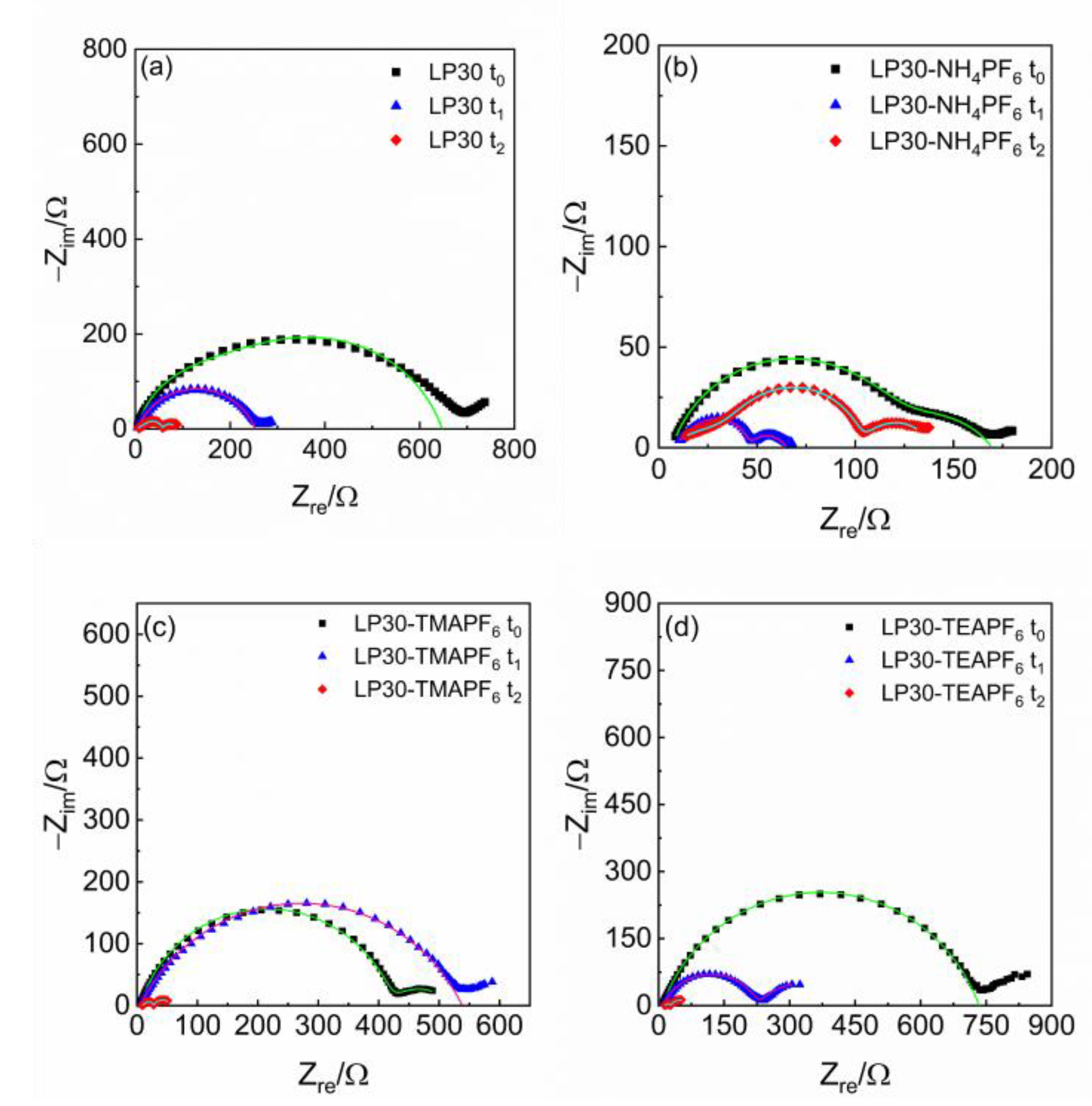
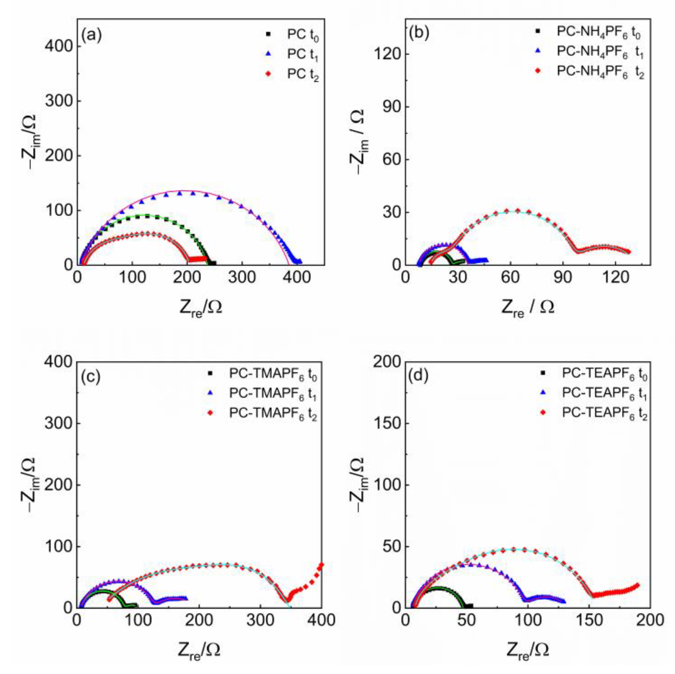
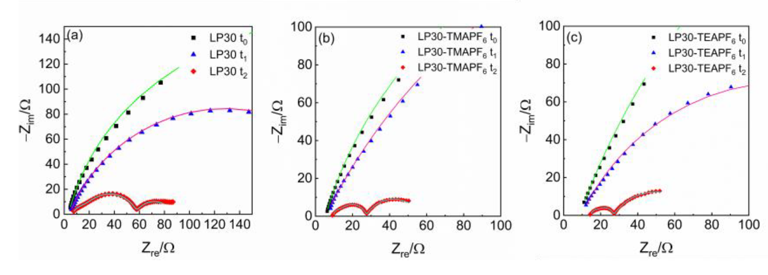
3.2. Impedance Spectroscopy Investigation
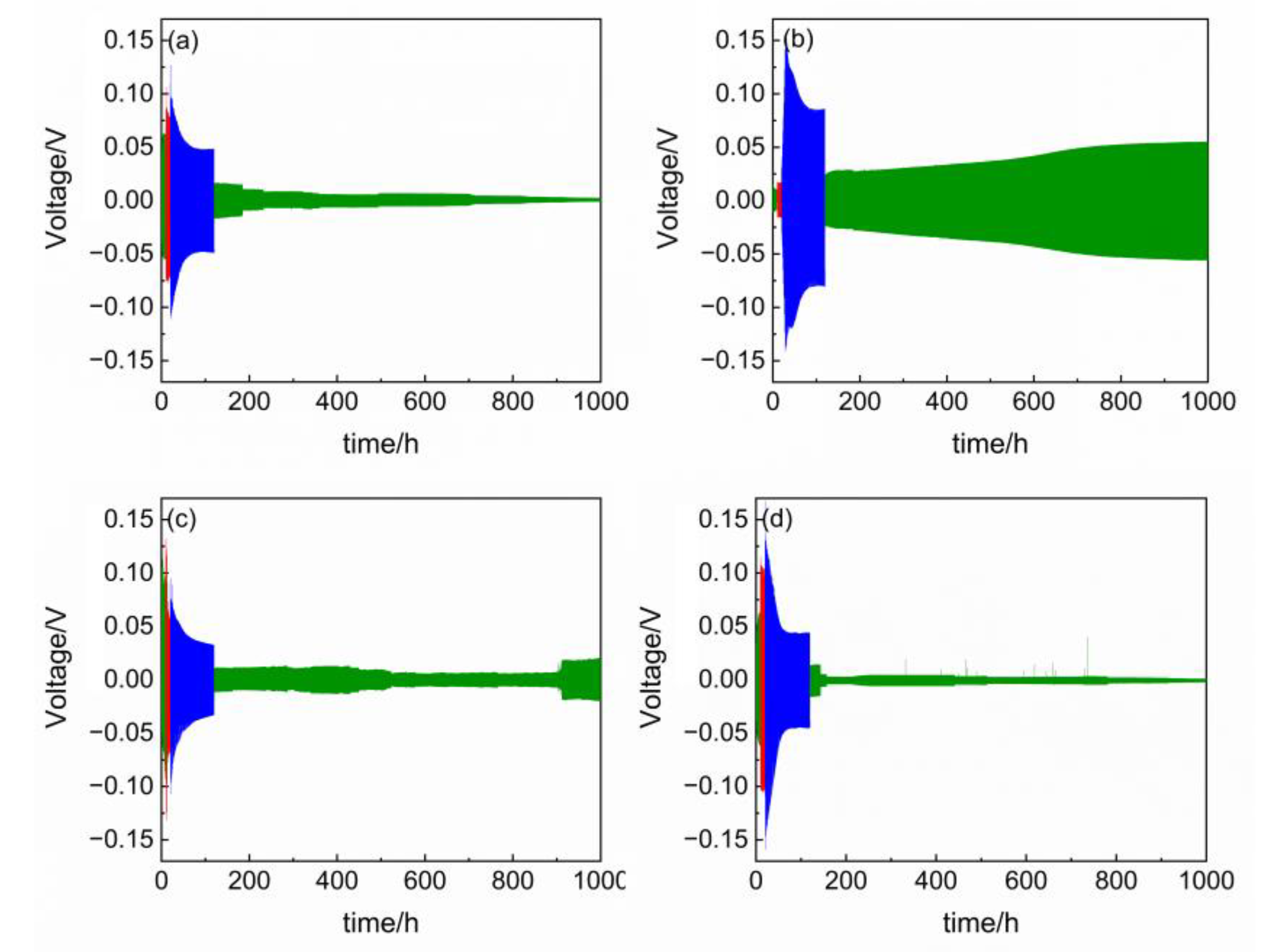
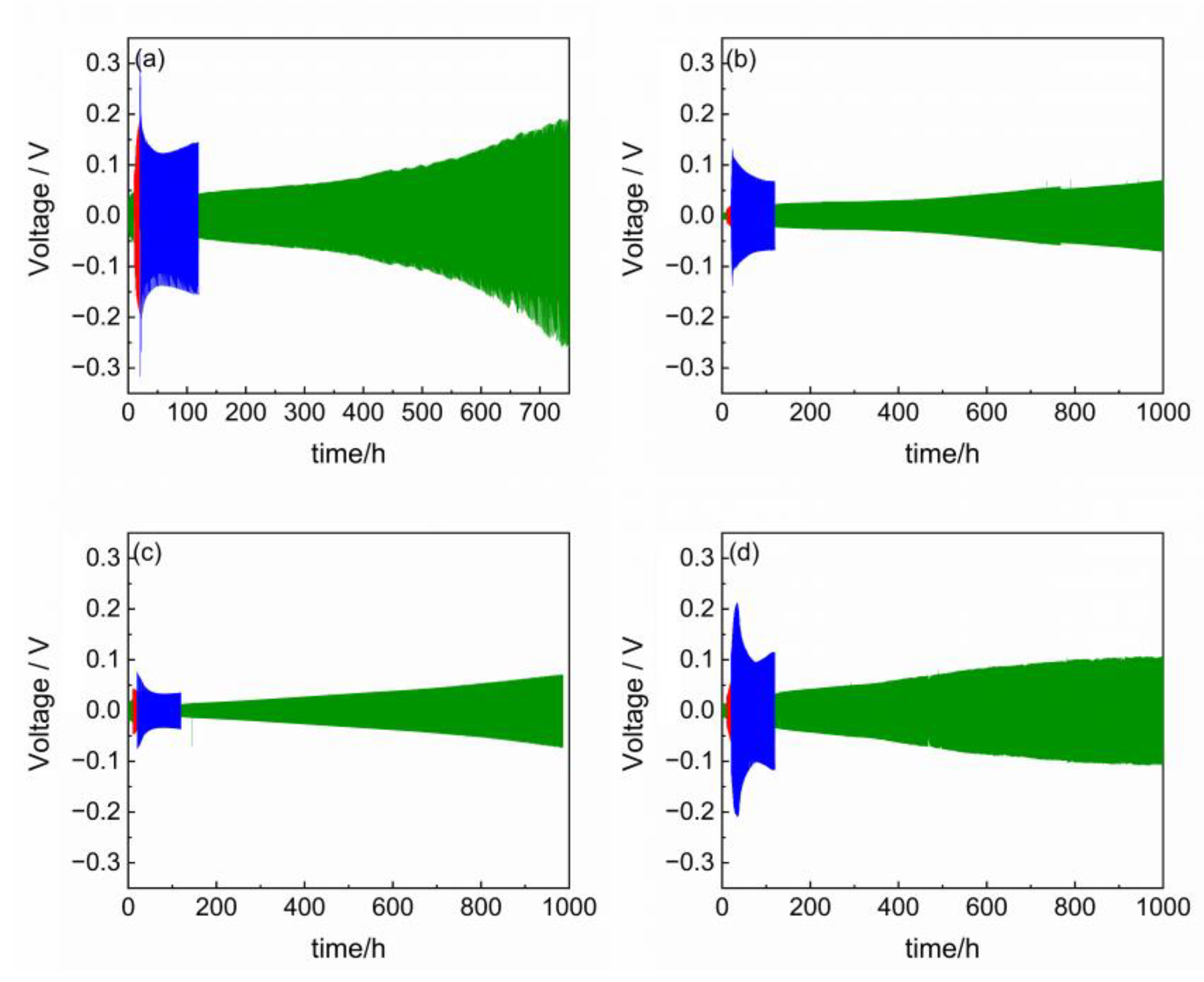
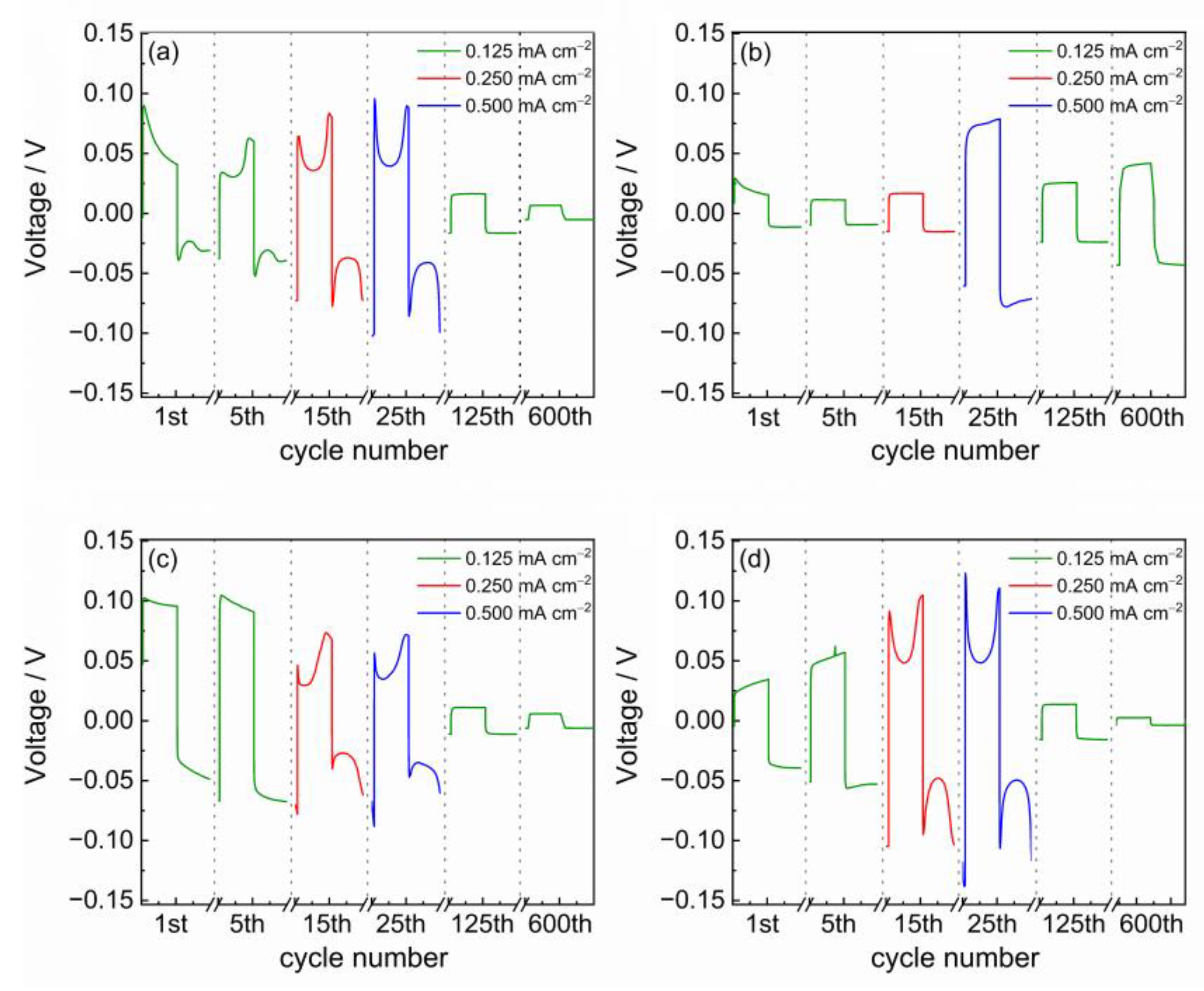
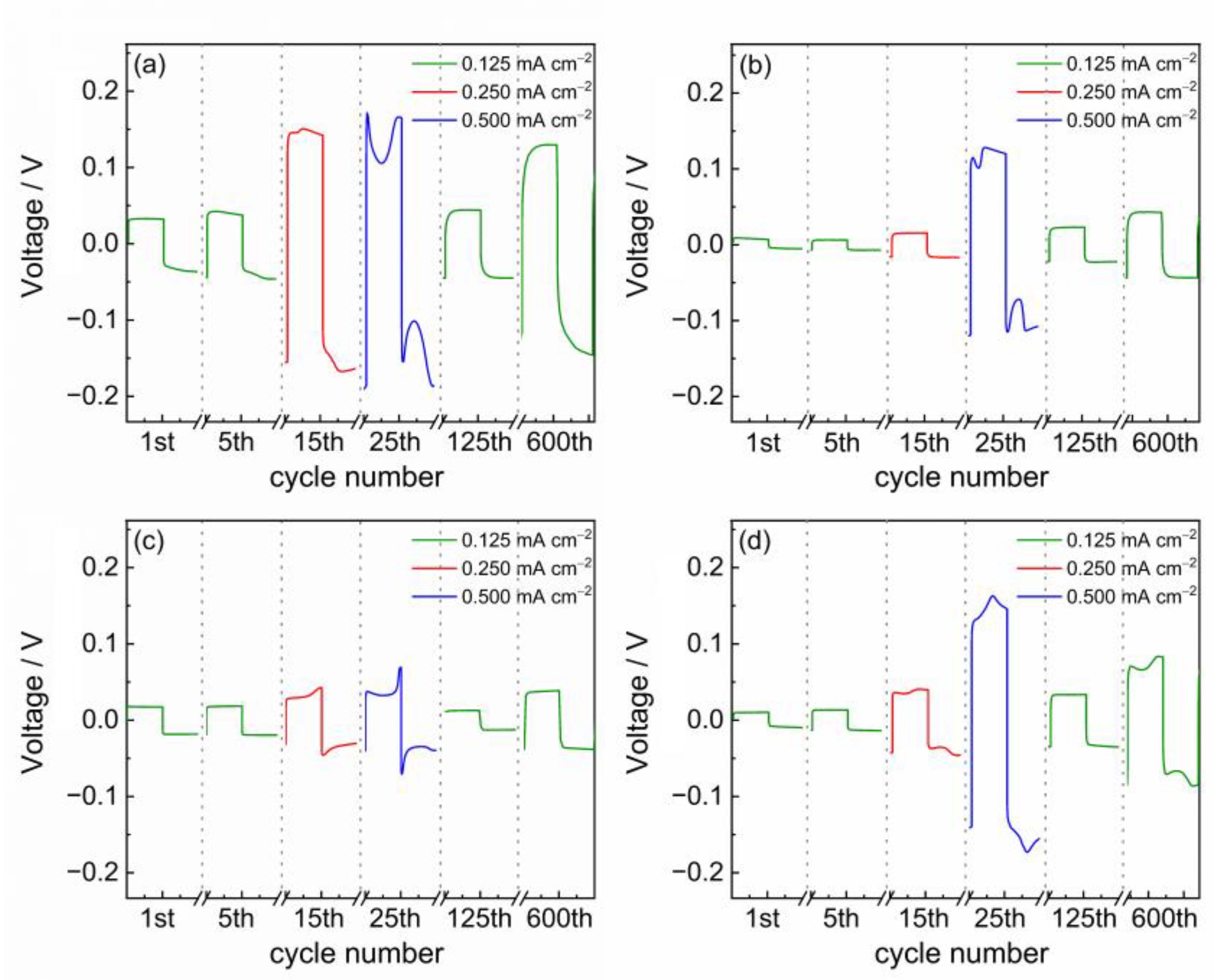
3.3. Voltage Profile Analysis
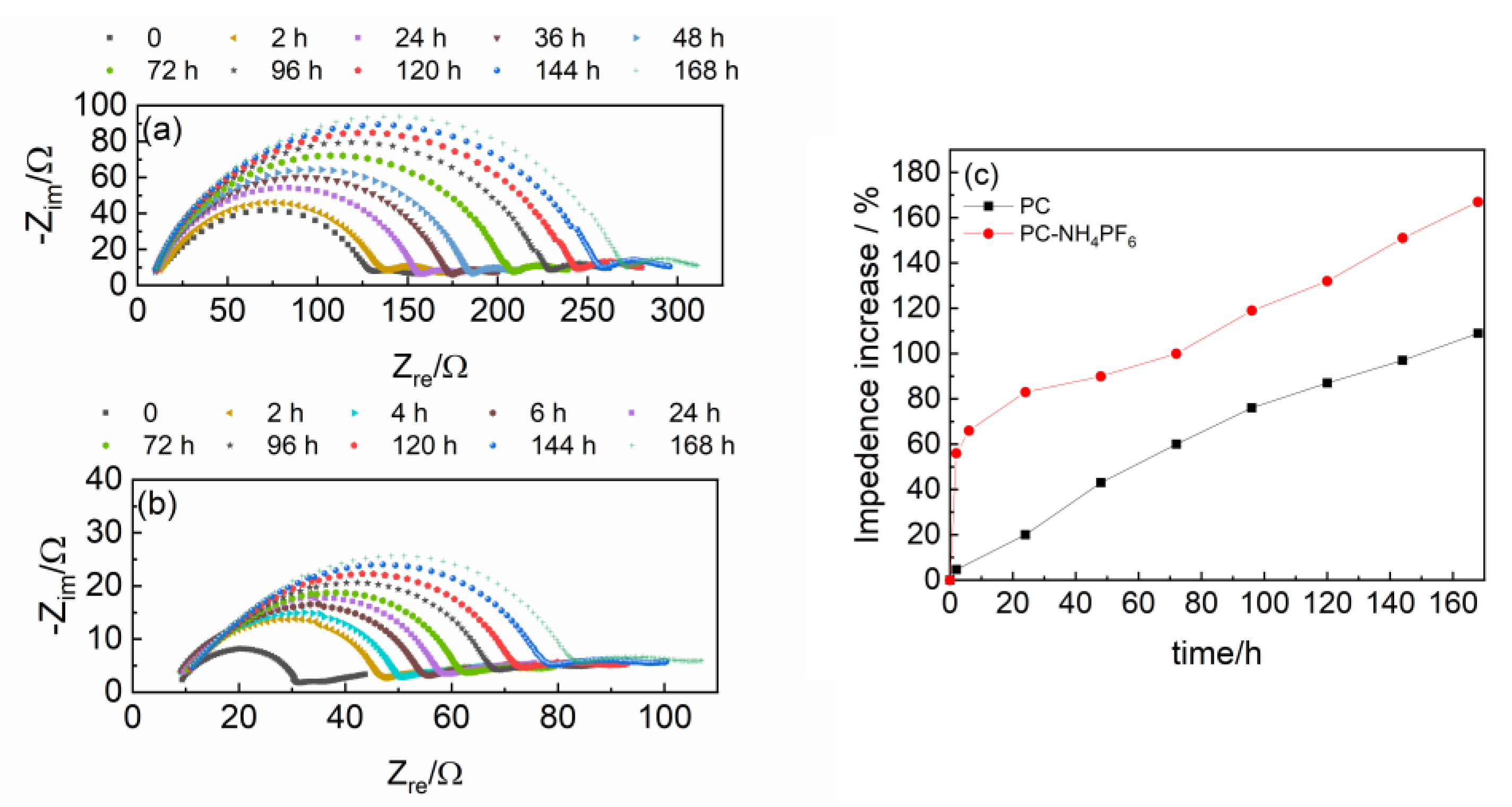
3.4. Impedance Spectroscopy Investigation on Spontaneously Formed Interlayers
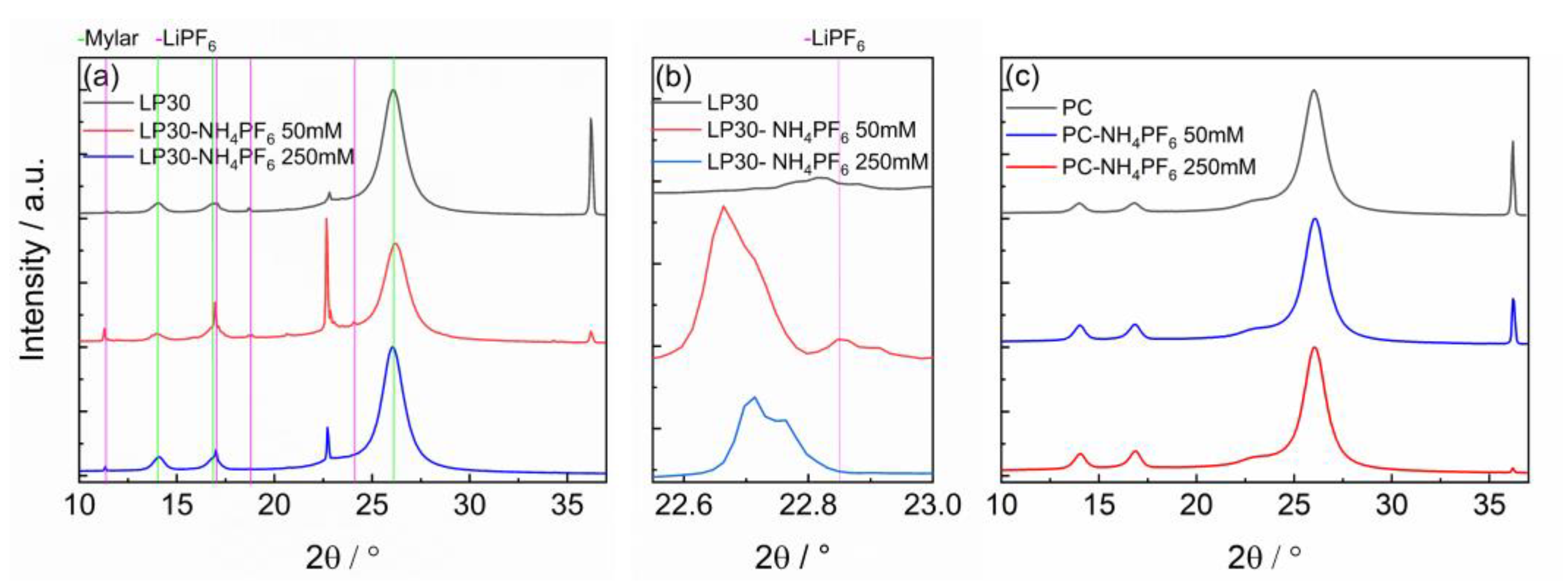
3.5. XRD Investigation
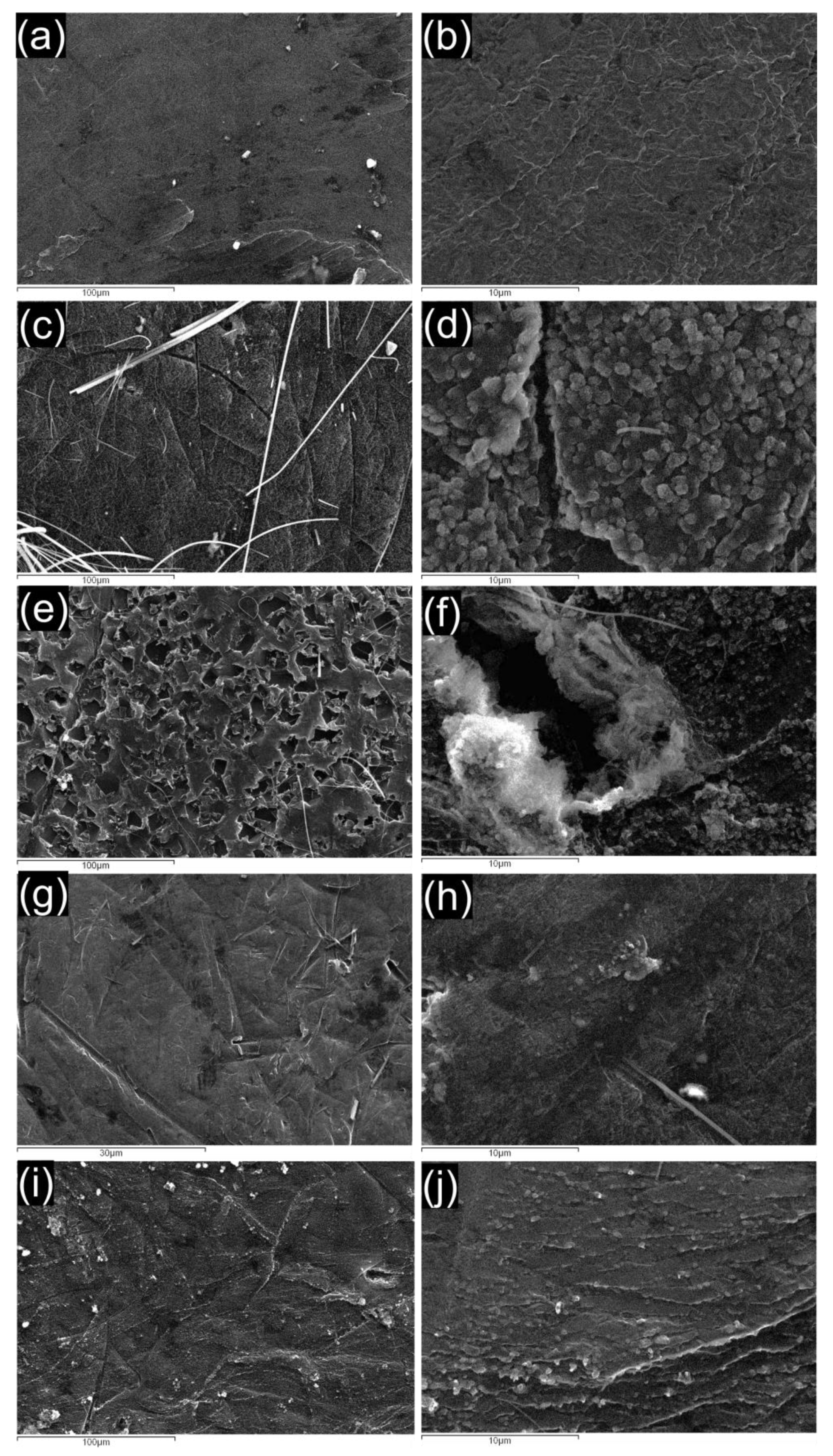
3.6. SEM Images
4. Discussion
5. Conclusions
Author Contributions
Funding
Data Availability Statement
Conflicts of Interest
Appendix A

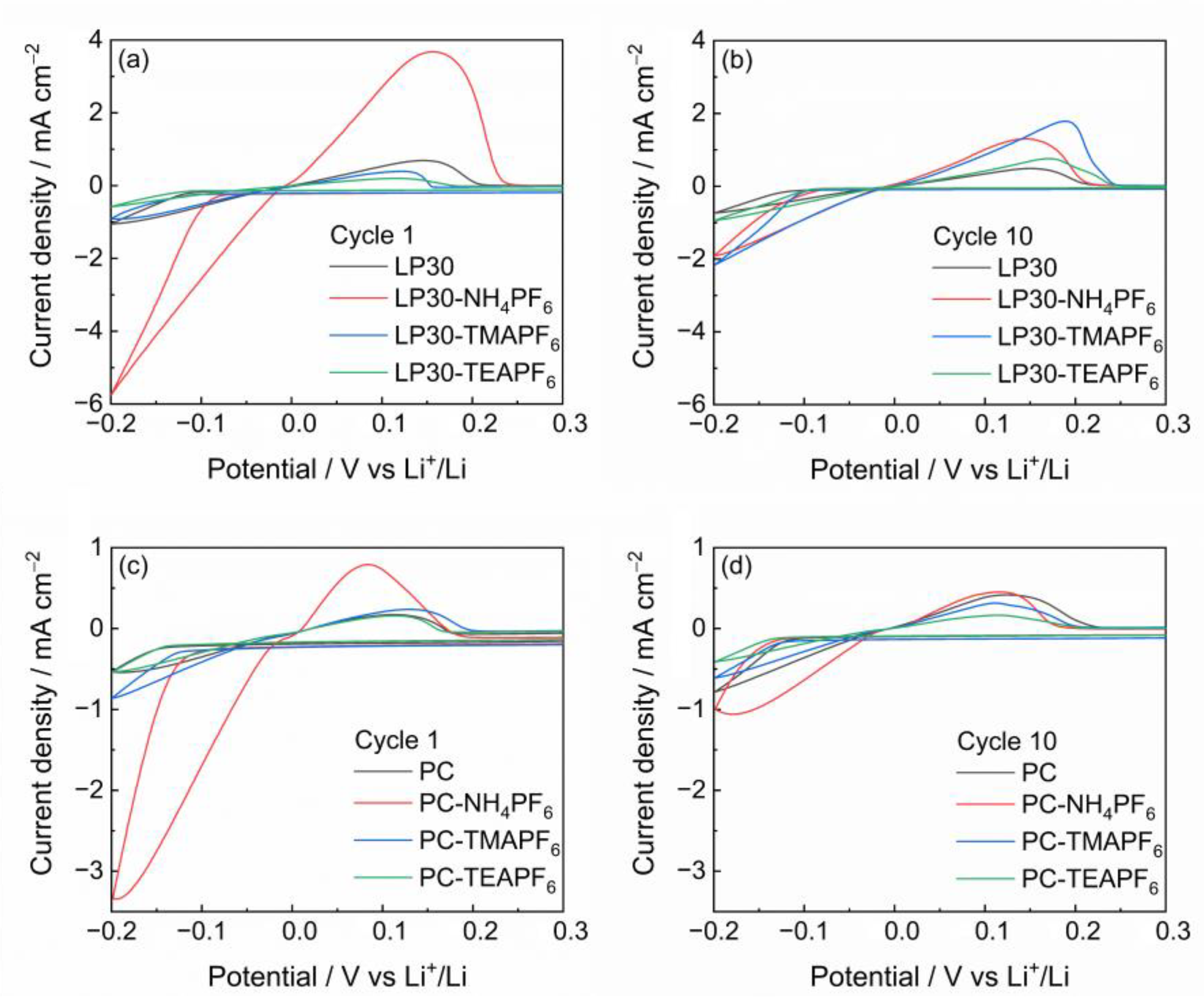
| Electrolyte | Reductiononset/mV | Oxidationpeak/mV | ||
|---|---|---|---|---|
| 1st Cycle | 10th Cycle | 1st Cycle | 10th Cycle | |
| LP30 | −100 | −100 | 150 | 160 |
| LP30-NH4PF6 | −75 | −80 | 160 | 150 |
| LP30-TMAPF6 | −100 | −90 | 120 | 190 |
| LP30-TEAPF6 | −100 | −90 | 120 | 190 |
| PC | −140 | −100 | 115 | 130 |
| PC-NH4PF6 | −90 | −100 | 80 | 115 |
| PC-TMAPF6 | −115 | −115 | 130 | 110 |
| PC-TEAPF6 | −135 | −125 | 115 | 115 |
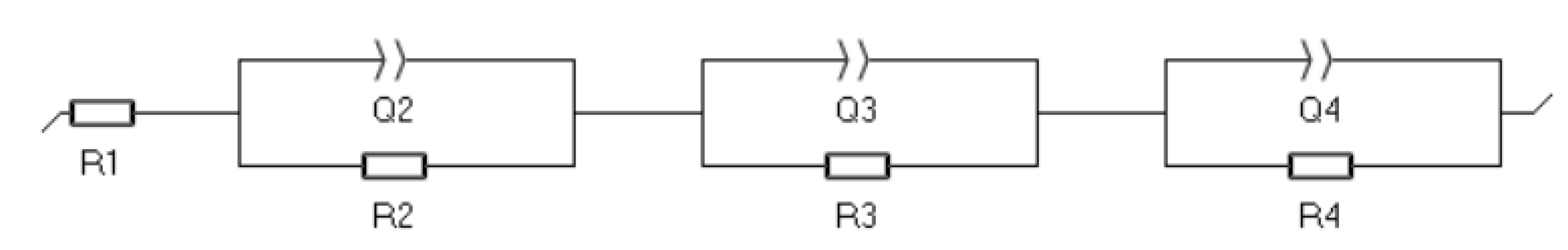
| LP30 | R1/Ω | R2/Ω | Q2/F sa−1 a | R3/Ω | Q3/F sa−1 a | R4/Ω | Q4/F sa−1 a |
|---|---|---|---|---|---|---|---|
| t0 | 3.4 ± 0.3 | 160 ± 90 | (2.1 ± 0.7)∙10−6 0.88 ± 0.07 | 500 ± 100 | (1.0 ± 0.2)∙10−5 0.79 ± 0.08 | ||
| t1 | 4.1 ± 0.2 | 249 ± 3 | (7.7 ± 0.4)∙10−6 0.759 ± 0.005 | ||||
| t2 | 6.6 ± 0.2 | 11 ± 1 | (9 ± 3) 10−6 0.80 ± 0.03 | 40 ± 1 | (2.4 ± 0.2) 10−5 0.02 | 29 ± 3 | (1.0 ± 0.1)∙10−2 0.77 ± 0.05 |
| LP30-NH4PF6 | R1/Ω | R2/Ω | Q2/F sa−1 a | R3/Ω | Q3/F sa−1 a | R4/Ω | Q4/F sa−1 a |
| t0 | 6.63 ± 0.09 | 112 ± 3 | (3.3 ± 0.2) 10−6 0.808 ± 0.006 | 51 ± 5 | (7 ± 1) 10−4 0.60 ± 0.05 | ||
| t1 | 6 ± 1 | 9 ± 3 | (4 ± 6) 10−5 0.6 ± 0.1 | 31 ± 2 | (3.8 ± 0.3)∙10−6 0.90 ± 0.02 | 19.4 ±0.4 | (3.8 ± 0.2) 10−3 0.69 ± 0.01 |
| t2 | 3.9 ± 0.9 | 47 ± 6 | (2.0 ± 0.7) 10−4 0.43 ± 0.03 | 55 ± 4 | (1.5 ± 0.1) 10−5 0.93 ± 0.02 | 33 ± 2 | (7.3 ± 0.5) 10−3 0.78 ± 0.04 |
| LP30-TMAPF | R1/Ω | R2/Ω | Q2/F sa−1 a | R3/Ω | Q3/F sa−1 a | R4/Ω | Q4/F sa−1 a |
| t0 | 5.3 ± 0.2 | 418 ± 8 | (4.5 ± 0.3)∙10−6 0.816 ± 0.006 | 90 ± 50 | (8 ± 3) 10−3 0.60 ± 0.05 | ||
| t1 | 5.4 ± 0.3 | 533 ± 7 | (1.21 ± 0.06)∙10−5 0.708 ± 0.06 | 31 ± 2 | (3.8 ± 0.3) 10−6 0.90 ± 0.02 | 19.4 ± 0.4 | (3.8 ± 0.2) 10−3 0.69 ± 0.01 |
| t2 | 9.6 ± 0.1 | 4 ± 1 | (2 ± 2) 10−6 1.0 ± 0.09 | 14 ± 1 | (2.1 ± 0.5) 10−5 0.88 ± 0.04 | 30 ± 2 | (1.9 ± 0.1) 10−3 0.69 ± 0.03 |
| LP30-TEAPF6 | R1/Ω | R2/Ω | Q2/F sa−1 a | R3/Ω | Q3/F sa−1 a | R4/Ω | Q4/F sa−1 a |
| t0 | 8.6 ± 0.2 | 725 ± 6 | (3.4 ±0.1)∙10−6 0.78 ± 0.04 | ||||
| t1 | 9.6 ± 0.2 | 219 ± 2 | (9.3 ±0.5)∙10−6 0.722 ± 0.005 | 180 ± 50 | (9.4 ±0.9)∙10−6 0.61 ± 0.07 | ||
| t2 | 14.7 ± 0.1 | 4 ± 1 | (2 ± 2) 10−6 1.0 ± 0.09 | 8 ± 1 | (2.4 ±0.6)∙10−5 0.89 ± 0.04 | 47 ± 2 | (2.47 ± 0.06)∙10−2 0.62 ± 0.01 |
| PC | R1/Ω | R2/Ω | Q2/F sa−1 a | R3/Ω | Q3/F sa−1 a | R4/Ω | Q4/F sa−1 a |
|---|---|---|---|---|---|---|---|
| t0 | 6.4 ± 0.2 | 231 ± 2 | (1.65 ± 0.09) 10−6 0.853 ± 0.005 | ||||
| t1 | 5.7 ± 0.3 | 380 ± 4 | (3.4 ± 0.2) 10−6 0.793 ± 0.006 | ||||
| t2 | 11.56 ± 0.09 | 74 ± 6 | (4.1 ± 0.3) 10−6 0.832 ± 0.009 | 119 ± 7 | (1.5 ± 0.1) 10−5 0.85 ± 0.02 | ||
| PC-NH4PF6 | R1/Ω | R2/Ω | Q2/F sa−1 a | R3/Ω | Q3/F sa−1 a | R4/Ω | Q4/F sa−1 a |
| t0 | 8.6 ± 0.2 | 17.1 ± 0.7 | (4 ± 1) 10−6 0.90 ± 0.02 | 16 ± 10 | (9 ± 3) 10−2 0.3 ± 0.1 | ||
| t1 | 7.5 ± 0.2 | 28 ± 1 | (4.5 ± 0.9) 10−6 0.88 ± 0.02 | 15 ± 5 | (1.5 ± 0.1) 10−5 0.85 ± 0.02 | ||
| t2 | 14.2 ± 0.2 | 12.3 ± 0.7 | (5 ± 2) 10−6 0.85 ± 0.03 | 70 ± 1 | (1.6 ± 0.1) 10−5 0.89 ± 0.01 | 36 ± 3 | (9.7 ± 0.8)∙10−3 0.67 ± 0.05 |
| PC-TMAPF6 | R1/Ω | R2/Ω | Q2/F sa−1 a | R3/Ω | Q3/F sa−1 a | R4/Ω | Q4/F sa−1 a |
| t0 | 6.5 ± 0.1 | 70 ± 1 | (2.3 ± 0.2) 10−6 0.85 ± 0.01 | 28 ± 6 | (2.4 ± 0.4) 10−2 0.43 ± 0.08 | ||
| t1 | 5.9 ± 0.1 | 120 ± 2 | (4.5 ± 0.3) 10−6 0.52 ± 0.01 | 71 ± 8 | (8.1 ± 0.9) 10−3 1.0 ± 0.1 | ||
| t2 * | 38.5 ± 0.5 | 238 ± 13 | (2.7 ± 0.2) 10−5 0.56 ± 0.01 | 74 ± 12 | (2.5 ± 0.3) 10−5 0.92 ± 0.04 | ||
| PC-TEAPF6 | R1/Ω | R2/Ω | Q2/F sa−1 a | R3/Ω | Q3/F sa−1 a | R4/Ω | Q4/F sa−1 a |
| t0 | 5.6 ± 0.2 | 41.6 ± 0.6 | (3.7 ± 0.5) 10−6 0.86 ± 0.01 | ||||
| t1 | 5.4 ± 0.1 | 91 ± 1 | (4.1 ± 0.3) 10−6 0.835 ± 0.007 | 35 ± 5 | (1.0 ± 0.2) 10−2 0.58 ± 0.08 | ||
| t2 | 7.5 ± 0.1 | 23 ± 8 | (5 ± 2) 10−6 0.89 ± 0.05 | 130 ± 10 | (1.5 ± 0.2) 10−6 0.80 ± 0.03 |


Appendix A.1. Test in Li||NMC Cells

References
- Zhang, H.; Li, C.; Eshetu, G.G.; Laruelle, S.; Grugeon, S.; Zaghib, K.; Julien, C.; Mauger, A.; Guyomard, D.; Rojo, T.; et al. From Solid-Solution Electrodes and the Rocking-Chair Concept to Today’s Batteries. Angew. Chem. 2020, 132, 542–546. [Google Scholar] [CrossRef]
- Xie, J.; Lu, Y.-C. A Retrospective on Lithium-ion Batteries. Nat. Commun. 2020, 11, 2499. [Google Scholar] [CrossRef] [PubMed]
- Steen, M.; Di Persio, F.; Boon-Brett, L.; Lebedeva, N.; EU Competitiveness in Advanced Li-Ion Batteries for E-Mobility and Stationary Storage Applications: Opportunities and Actions. Publications Office. 2018. Available online: https://data.europa.eu/doi/10.2760/75757 (accessed on 1 December 2022).
- Aurbach, D.; Ein-Ely, Y.; Zaban, A. The Surface Chemistry of Lithium Electrodes in Alkyl Carbonate Solutions. J. Electrochem. Soc. 1994, 141, L1–L3. [Google Scholar] [CrossRef]
- Aurbach, D. Review of Selected Electrode–Solution Interactions Which Determine the Performance of Li and Li Ion Batteries. J. Power Sources 2000, 89, 206–218. [Google Scholar] [CrossRef]
- Peled, E.; Menkin, S. SEI: Past, Present and Future. J. Electrochem. Soc. 2017, 164, A1703–A1719. [Google Scholar] [CrossRef]
- Ein-Eli, Y. A New Perspective on the Formation and Structure of the Solid Electrolyte Interface at the Graphite Anode of Li-Ion Cells. Electrochem. Solid-State Lett. 1999, 2, 212. [Google Scholar] [CrossRef]
- Selvamani, V.; Suryanarayanan, V.; Velayutham, D.; Gopukumar, S. Asymmetric tetraalkyl ammonium cation-based ionic liquid as an electrolyte for lithium-ion battery applications. J. Solid State Electrochem. 2016, 20, 2283–2293. [Google Scholar] [CrossRef]
- Li, J.; Liu, S.; Cui, Y.; Zhang, S.; Wu, X.; Xiang, J.; Li, M.; Wang, X.; Xia, X.; Gu, C.; et al. Potassium Hexafluorophosphate Additive Enables Stable Lithium-Sulfur Batteries. ACS Appl. Mater. Interfaces 2020, 12, 56017–56026. [Google Scholar] [CrossRef]
- Chazalviel, J.-N. Electrochemical Aspects of the Generation of Ramified Metallic Electrodeposits. Phys. Rev. A 1990, 42, 7355–7367. [Google Scholar] [CrossRef]
- Peled, E. The Electrochemical Behavior of Alkali and Alkaline Earth Metals in Nonaqueous Battery Systems—The Solid Electrolyte Interphase Model. J. Electrochem. Soc. 1979, 126, 2047–2051. [Google Scholar] [CrossRef]
- Jana, A.; Woo, S.I.; Vikrant, K.S.N.; García, R.E. Electrochemomechanics of Lithium Dendrite Growth. Energy Environ. Sci. 2019, 12, 3595–3607. [Google Scholar] [CrossRef]
- Ren, W.; Zheng, Y.; Cui, Z.; Tao, Y.; Li, B.; Wang, W. Recent Progress of Functional Separators in Dendrite Inhibition for Lithium Metal Batteries. Energy Stor. Mater. 2021, 35, 157–168. [Google Scholar] [CrossRef]
- Chen, S.; Li, Y.; Wang, Y.; Li, Z.; Peng, C.; Feng, Y.; Feng, W. Cross-linked Single-Ion Solid Polymer Electrolytes with Alternately Distributed Lithium Sources and Ion-Conducting Segments for Lithium Metal Batteries. Macromolecules 2021, 54, 9135–9144. [Google Scholar] [CrossRef]
- Zhang, X.; Wang, A.; Liu, X.; Luo, J. Dendrites in Lithium Metal Anodes: Suppression, Regulation, and Elimination. Acc. Chem. Res. 2019, 52, 3223–3232. [Google Scholar] [CrossRef]
- Ota, H.; Shima, K.; Ue, M.; Yamaki, J. Effect of vinylene carbonate as additive to electrolyte for lithium metal anode. Electrochim. Acta 2004, 49, 565–572. [Google Scholar] [CrossRef]
- Heine, J.; Hilbig, P.; Qi, X.; Niehoff, P.; Winter, M.; Bieker, P. Fluoroethylene Carbonate as Electrolyte Additive in Tetraethylene Glycol Dimethyl Ether Based Electrolytes for Application in Lithium Ion and Lithium Metal Batteries. J. Electrochem. Soc. 2015, 162, A1094–A1101. [Google Scholar] [CrossRef]
- Mogi, R.; Inaba, M.; Jeong, S.; Iriyama, Y.; Abe, T.; Ogumi, Z. Effects of some organic additives on lithium deposition in propylene carbonate. J. Electrochem. Soc. 2002, 149, A1578–A1583. [Google Scholar] [CrossRef]
- Zhang, X.-Q.; Cheng, X.-B.; Chen, X.; Yan, C.; Zhang, Q. Fluoroethylene Carbonate Additives to Render Uniform Li Deposits in Lithium Metal Batteries. Adv. Funct. Mater. 2017, 27, 1605989. [Google Scholar] [CrossRef]
- Zhang, H.; Eshetu, G.G.; Judez, X.; Li, C.; Rodriguez-Martínez, L.M.; Armand, M. Electrolyte Additives for Lithium Metal Anodes and Rechargeable Lithium Metal Batteries: Progress and Perspectives. Angew. Chem. Int. Ed. 2018, 57, 15002–15027. [Google Scholar] [CrossRef]
- Wang, A.; Kadam, S.; Li, H.; Shi, S.; Qi, Y. Review on modeling of the anode solid electrolyte interphase (SEI) for lithium-ion batteries. Npj Comput. Mater. 2018, 4, 15. [Google Scholar] [CrossRef] [Green Version]
- Wang, Z.; Wang, Y.; Wu, C.; Pang, W.K.; Mao, J.; Guo, Z. Constructing nitrided interfaces for stabilizing Li metal electrodes in liquid electrolytes. Chem. Sci. 2021, 12, 8945–8966. [Google Scholar] [CrossRef]
- Baloch, M.; Shanmukaraj, D.; Bondarchuk, O.; Bekaert, E.; Rojo, T.; Armand, M. Variations on Li3N Protective Coating Using Ex-Situ and In-Situ Techniques for Li Degrees in Sulphur Batteries. Energy Stor. Mater. 2017, 9, 141–149. [Google Scholar]
- Tiyapiboonchaiya, C.; Pringle, J.M.; Sun, J.; Byrne, N.; Howlett, P.C.; MacFarlane, D.R.; Forsyth, M. The zwitterion effect in high-conductivity polyelectrolyte materials. Nat. Mater. 2004, 3, 29–32. [Google Scholar] [CrossRef] [PubMed]
- Li, S.; Zhang, W.; Wu, Q.; Fan, L.; Wang, X.; Wang, X.; Shen, Z.; He, Y.; Lu, Y. Synergistic Dual-Additive Electrolyte Enables Practical Lithium-Metal Batteries. Angew. Chem. Int. Ed. 2020, 59, 14935–14941. [Google Scholar] [CrossRef] [PubMed]
- Ding, F.; Xu, W.; Graff, G.L.; Zhang, J.; Sushko, M.L.; Chen, X.; Shao, Y.; Engelhard, M.H.; Nie, Z.; Xiao, J.; et al. Dendrite-Free Lithium Deposition via Self-Healing Electrostatic Shield Mechanism. J. Am. Chem. Soc. 2013, 135, 4450–4456. [Google Scholar] [CrossRef]
- Lin, D.; Liu, Y.; Pei, A.; Cui, Y. Nanoscale Perspective: Materials Designs and Understandings in Lithium Metal Anodes. Nano Res. 2017, 10, 4003–4026. [Google Scholar] [CrossRef]
- Busche, M.R.; Drossel, T.; Leichtweiss, T.; Weber, D.A.; Falk, M.; Schneider, M.; Reich, M.-L.; Sommer, H.; Adelhelm, P.; Janek, J. Dynamic Formation of a Solid-Liquid Electrolyte Interphase and Its Consequences for Hybrid-Battery Concepts. Nat. Chem. 2016, 8, 426–434. [Google Scholar] [CrossRef] [PubMed]
- Hu, Z.; Zhang, S.; Dong, S.; Li, Q.; Cui, G.; Chen, L. Self-Stabilized Solid Electrolyte Interface on a Host-Free Li-Metal Anode toward High Areal Capacity and Rate Utilization. Chem. Mater. 2018, 30, 4039–4047. [Google Scholar] [CrossRef]
- Woo, J.-J.; Maroni, V.A.; Liu, G.; Vaughey, J.T.; Gosztola, D.J.; Amine, K.; Zhang, Z. Symmetrical Impedance Study on Inactivation Induced Degradation of Lithium Electrodes for Batteries Beyond Lithium-Ion. J. Electrochem. Soc. 2014, 161, A827–A830. [Google Scholar] [CrossRef]
- Metzger, M.; Strehle, B.; Solchenbach, S.; Gasteiger, H.A. Origin of H2 Evolution in LIBs: H2O Reduction vs. Electrolyte Oxidation. J. Electrochem. Soc. 2016, 163, A798–A809. [Google Scholar] [CrossRef]
- Naoi, K.; Mori, M.; Shinagawa, Y. Study of Deposition and Dissolution Processes of Lithium in Carbonate-Based Solutions by Means of the Quartz-Crystal Microbalance. J. Electrochem. Soc. 1996, 143, 2517–2522. [Google Scholar] [CrossRef]
- Xu, K. Nonaqueous Liquid Electrolytes for Lithium-Based Rechargeable Batteries. Chem. Rev. 2004, 104, 4303–4418. [Google Scholar] [CrossRef]
- Bieker, G.; Winter, M.; Bieker, P. Electrochemical in situ investigations of SEI and dendrite formation on the lithium metal anode. Phys. Chem. Chem. Phys. 2015, 17, 8670–8679. [Google Scholar] [CrossRef] [Green Version]
- Barton, J.L.; Bockris, J.O. The electrolytic growth of dendrites from ionic solutions. Proc. R. Soc. London Ser. A 1962, 268, 485–505. [Google Scholar]
- Chen, K.-H.; Wood, K.N.; Kazyak, E.; LePage, W.S.; Davis, A.L.; Sanchez, A.J.; Dasgupta, N.P. Dead Lithium: Mass Transport Effects on Voltage, Capacity, and Failure of Lithium Metal Anodes. J. Mater. Chem. A 2017, 5, 11671–11681. [Google Scholar] [CrossRef]
- Li, Z.; Ji, W.; Wang, T.-X.; Ding, X.; Han, B.-H.; Feng, W. Maximized lithiophilic carbonyl units in covalent organic frameworks as effective Li ion regulators for lithium metal batteries. Chem. Eng. J. 2022, 437, 135293. [Google Scholar] [CrossRef]


Disclaimer/Publisher’s Note: The statements, opinions and data contained in all publications are solely those of the individual author(s) and contributor(s) and not of MDPI and/or the editor(s). MDPI and/or the editor(s) disclaim responsibility for any injury to people or property resulting from any ideas, methods, instructions or products referred to in the content. |
© 2023 by the authors. Licensee MDPI, Basel, Switzerland. This article is an open access article distributed under the terms and conditions of the Creative Commons Attribution (CC BY) license (https://creativecommons.org/licenses/by/4.0/).
Share and Cite
Di Cillo, D.; Bargnesi, L.; Lacarbonara, G.; Arbizzani, C. Ammonium and Tetraalkylammonium Salts as Additives for Li Metal Electrodes. Batteries 2023, 9, 142. https://doi.org/10.3390/batteries9020142
Di Cillo D, Bargnesi L, Lacarbonara G, Arbizzani C. Ammonium and Tetraalkylammonium Salts as Additives for Li Metal Electrodes. Batteries. 2023; 9(2):142. https://doi.org/10.3390/batteries9020142
Chicago/Turabian StyleDi Cillo, Dario, Luca Bargnesi, Giampaolo Lacarbonara, and Catia Arbizzani. 2023. "Ammonium and Tetraalkylammonium Salts as Additives for Li Metal Electrodes" Batteries 9, no. 2: 142. https://doi.org/10.3390/batteries9020142