
A Review on Thermal Behaviors and Thermal Management Systems for Supercapacitors
 , ,
, ,  , , ,
, , ,
Abstract
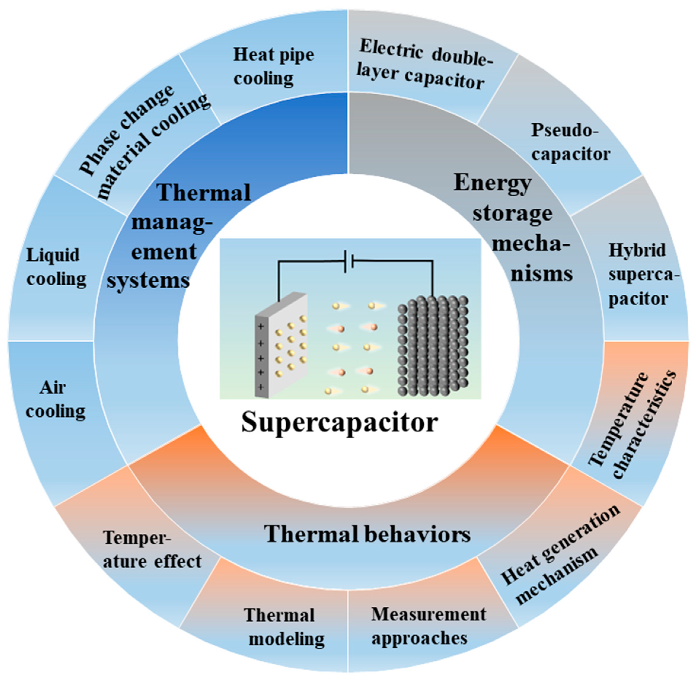
:1. Introduction
2. Energy Storage Mechanisms of Supercapacitors
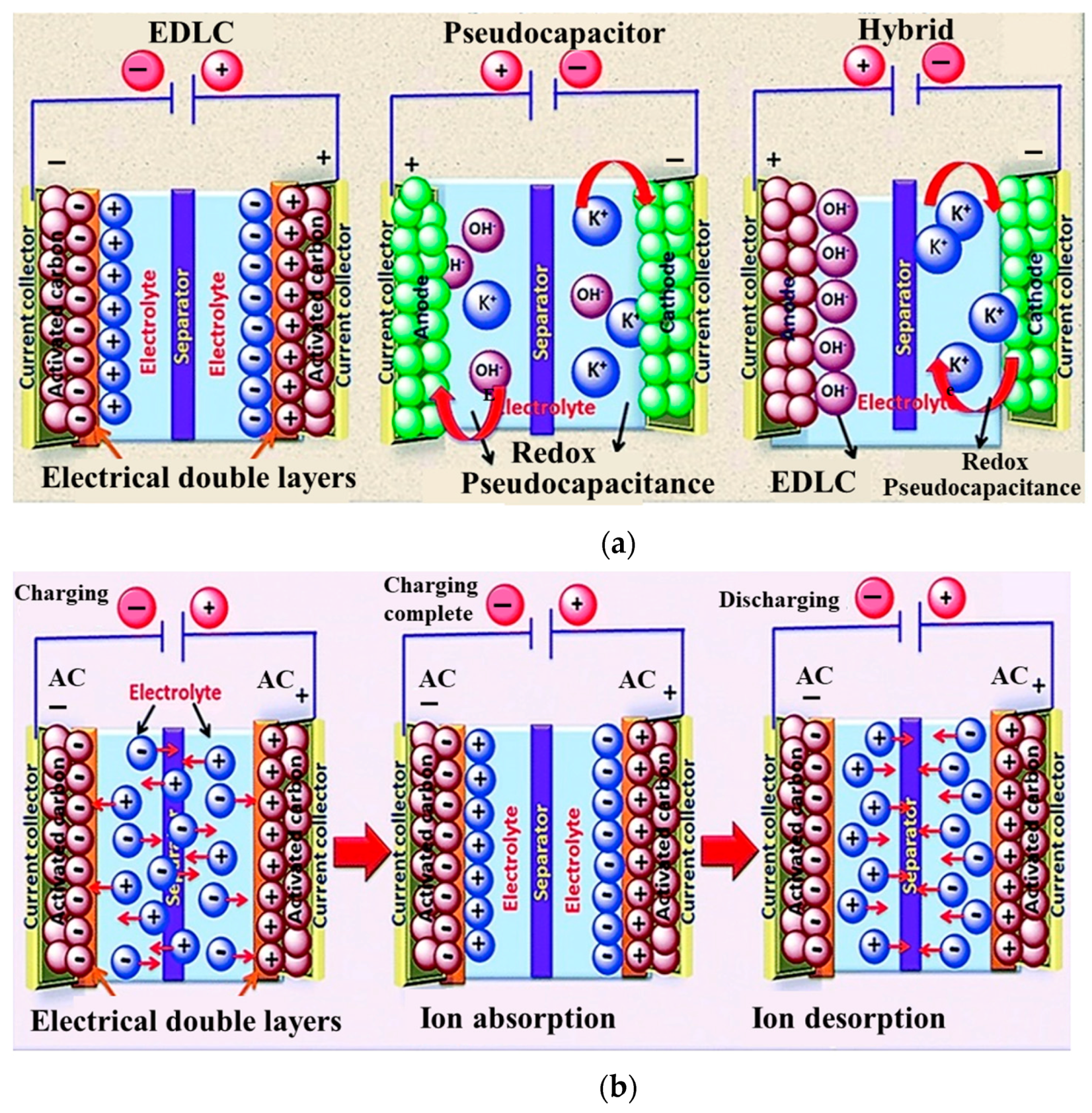
2.1. Electric Double-Layer Capacitor
2.2. Pseudocapacitor
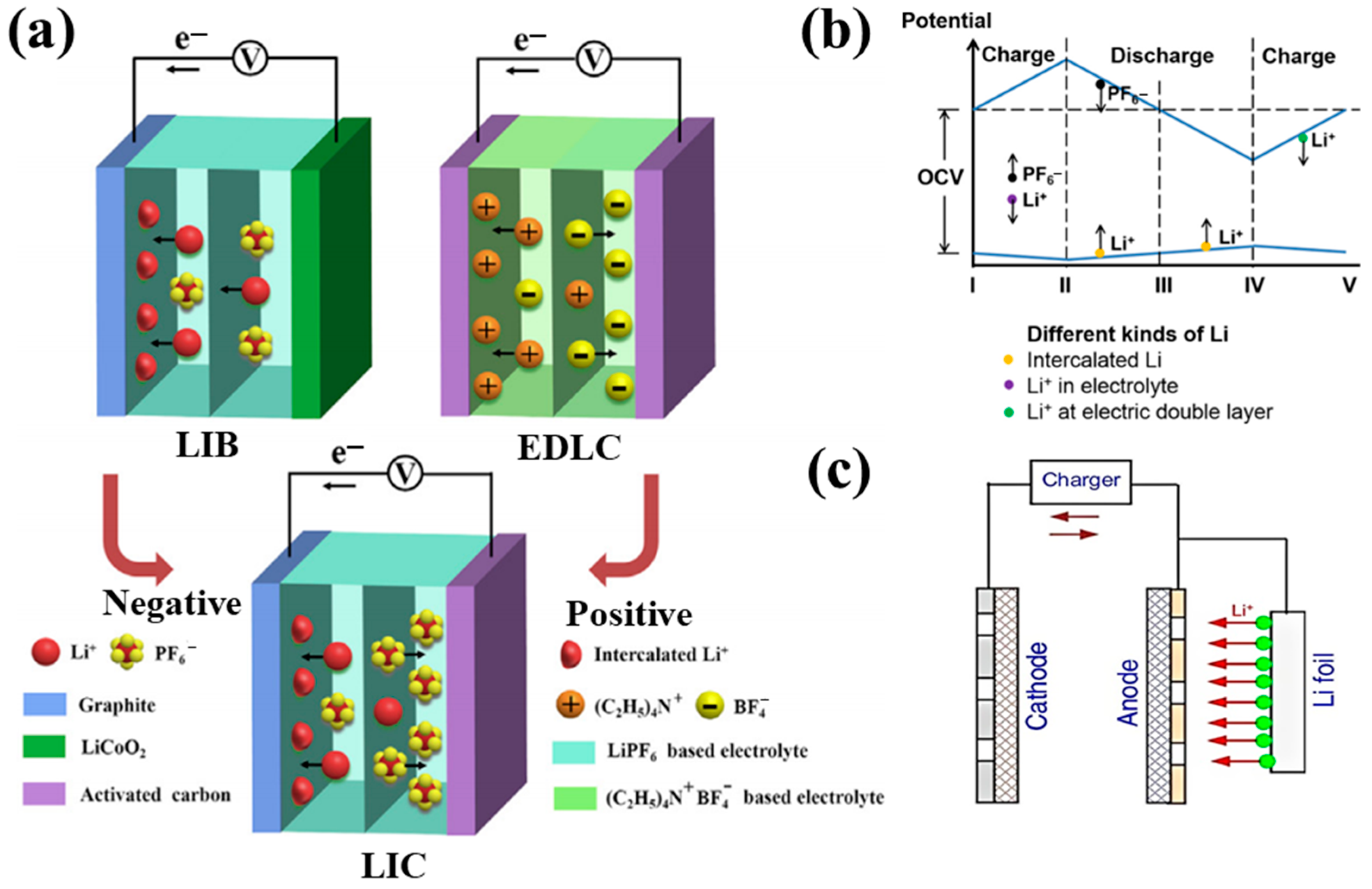
2.3. Hybrid Supercapacitor
3. Thermal Behaviors of Supercapacitors
3.1. Temperature Characteristics
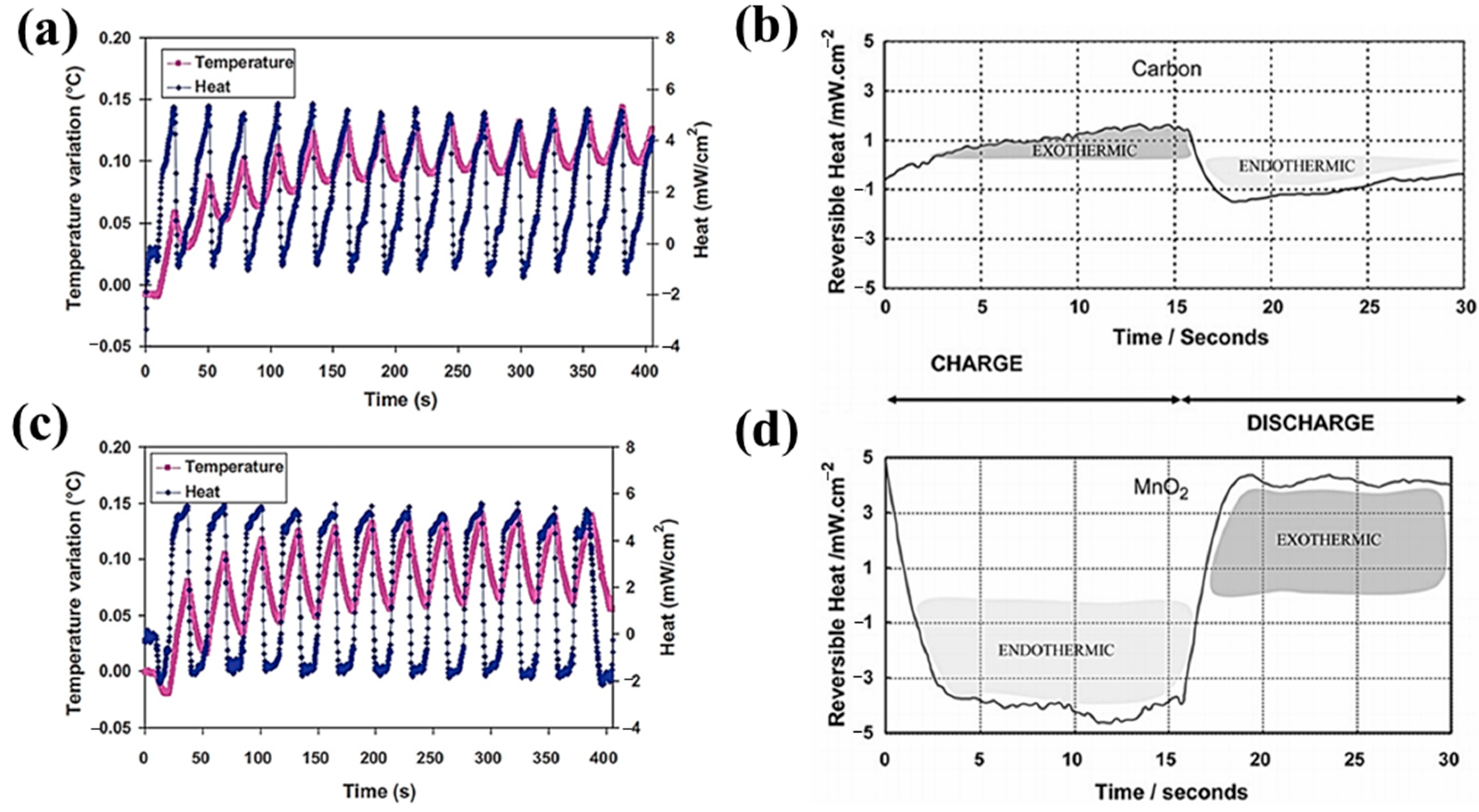
3.2. Heat Generation Mechanism for Supercapacitors
3.2.1. Electric Double-Layer Capacitor
3.2.2. Pseudocapacitor
3.2.3. Hybrid Supercapacitor
3.3. Measurement Approaches
3.3.1. Heat Generation Rate Measurement
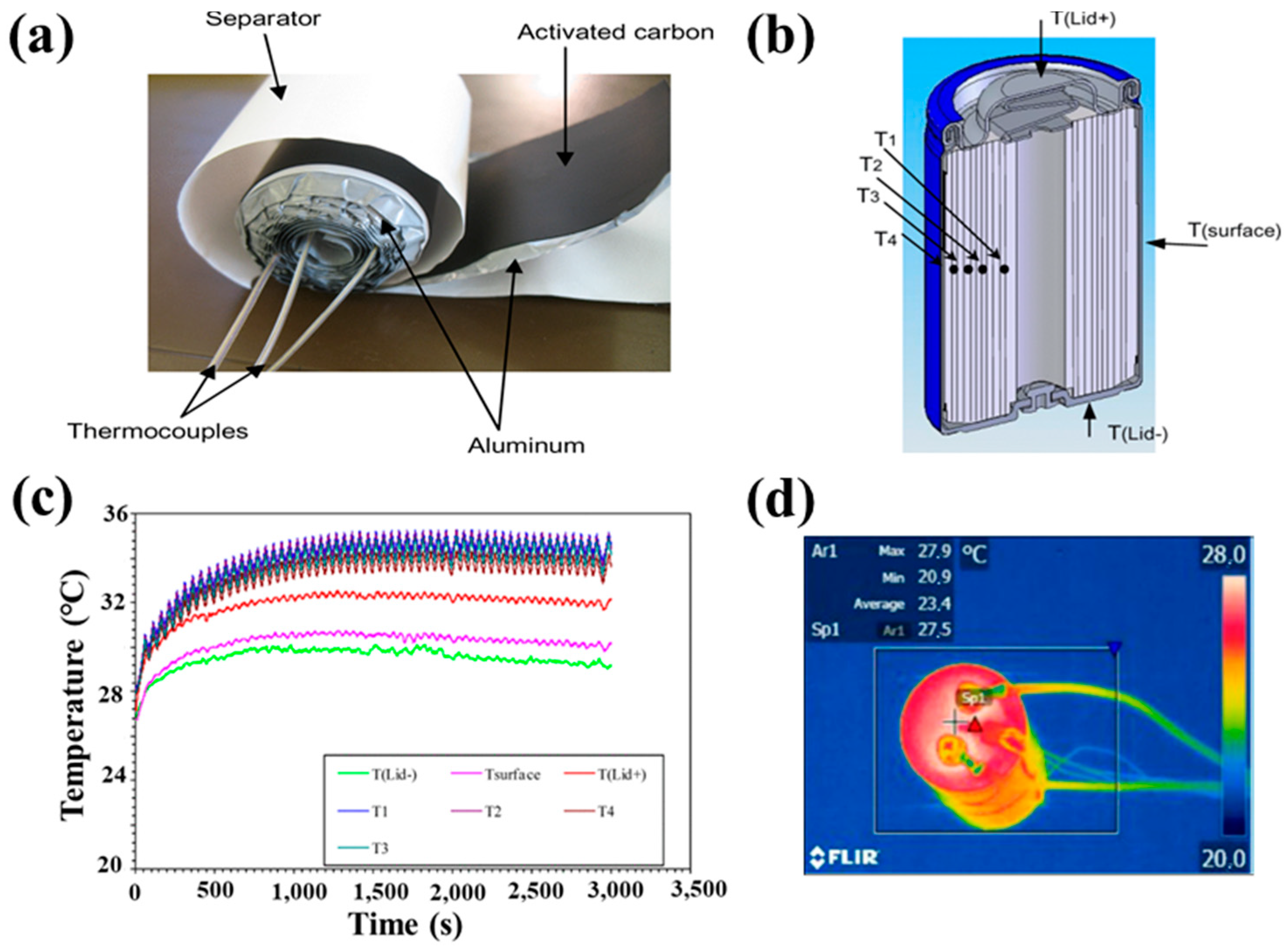
3.3.2. Temperature Measurement Techniques
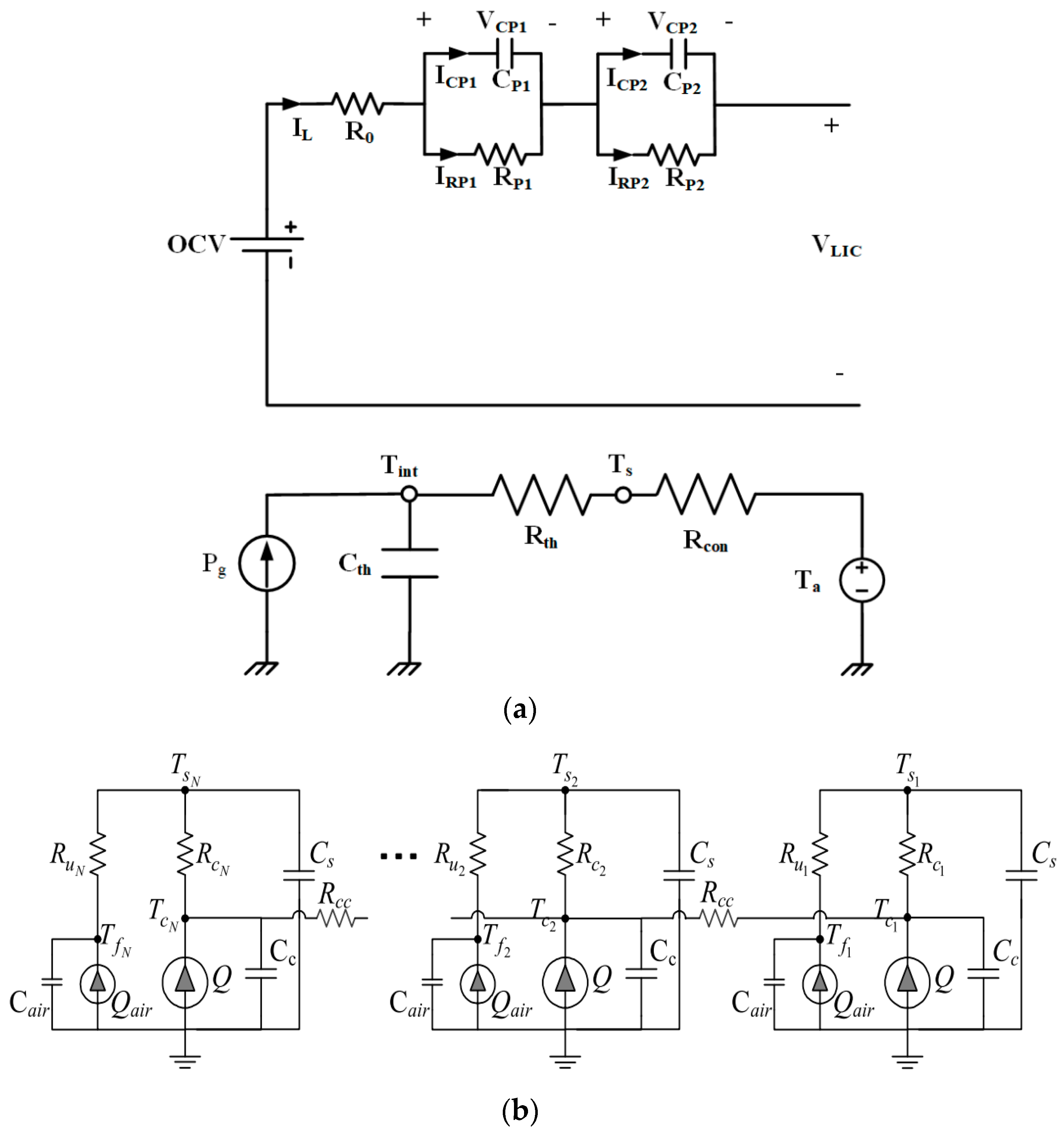
3.4. Thermal Modeling of Supercapacitors
3.4.1. Zero-Dimensional Model
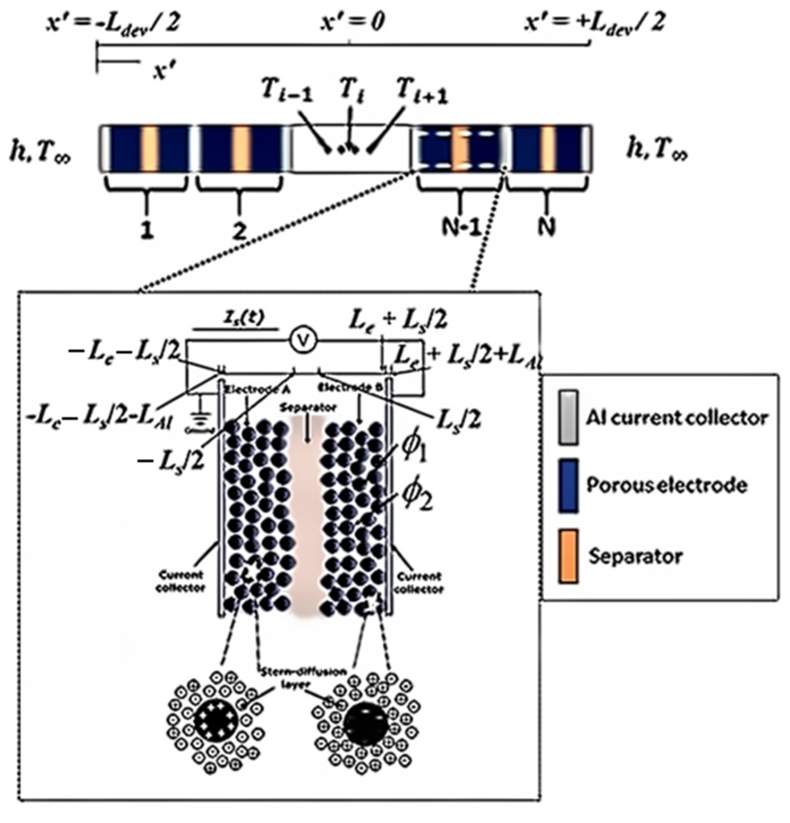
3.4.2. One-Dimensional Model
3.4.3. Three-Dimensional Model
3.5. Effect of Temperature on Supercapacitors
3.5.1. Effect on Electrolyte
3.5.2. Effect on Separator
3.5.3. Effect on Electrodes
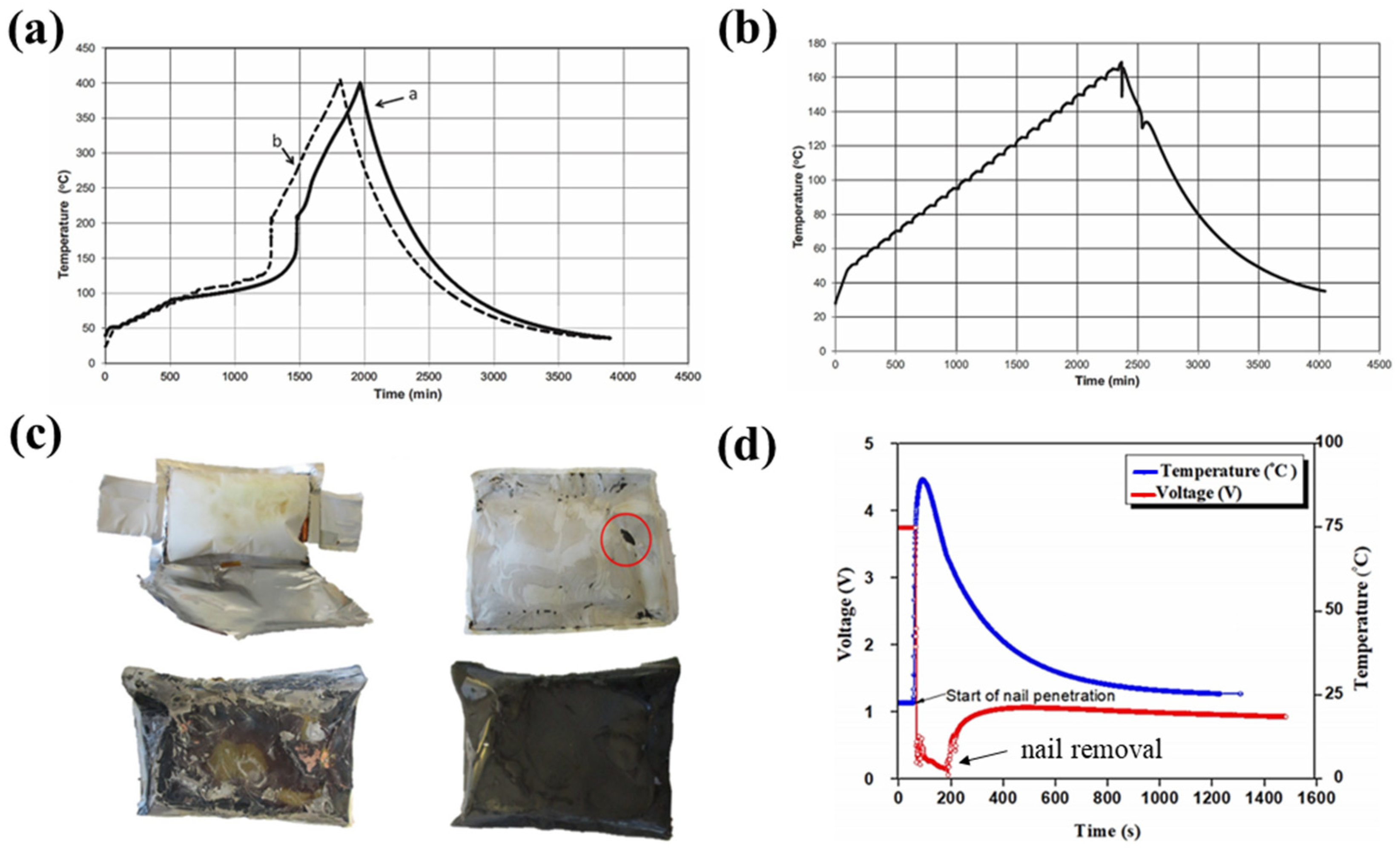
3.5.4. Thermal Runaway
4. Thermal Management System
4.1. The Necessity for Thermal Management
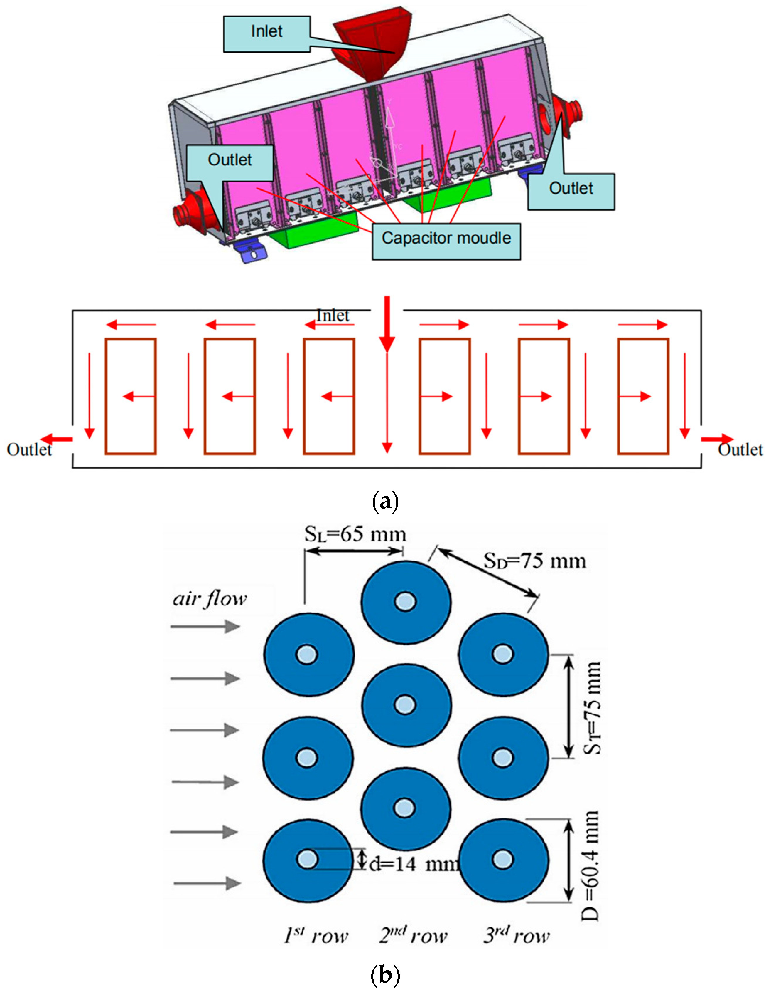
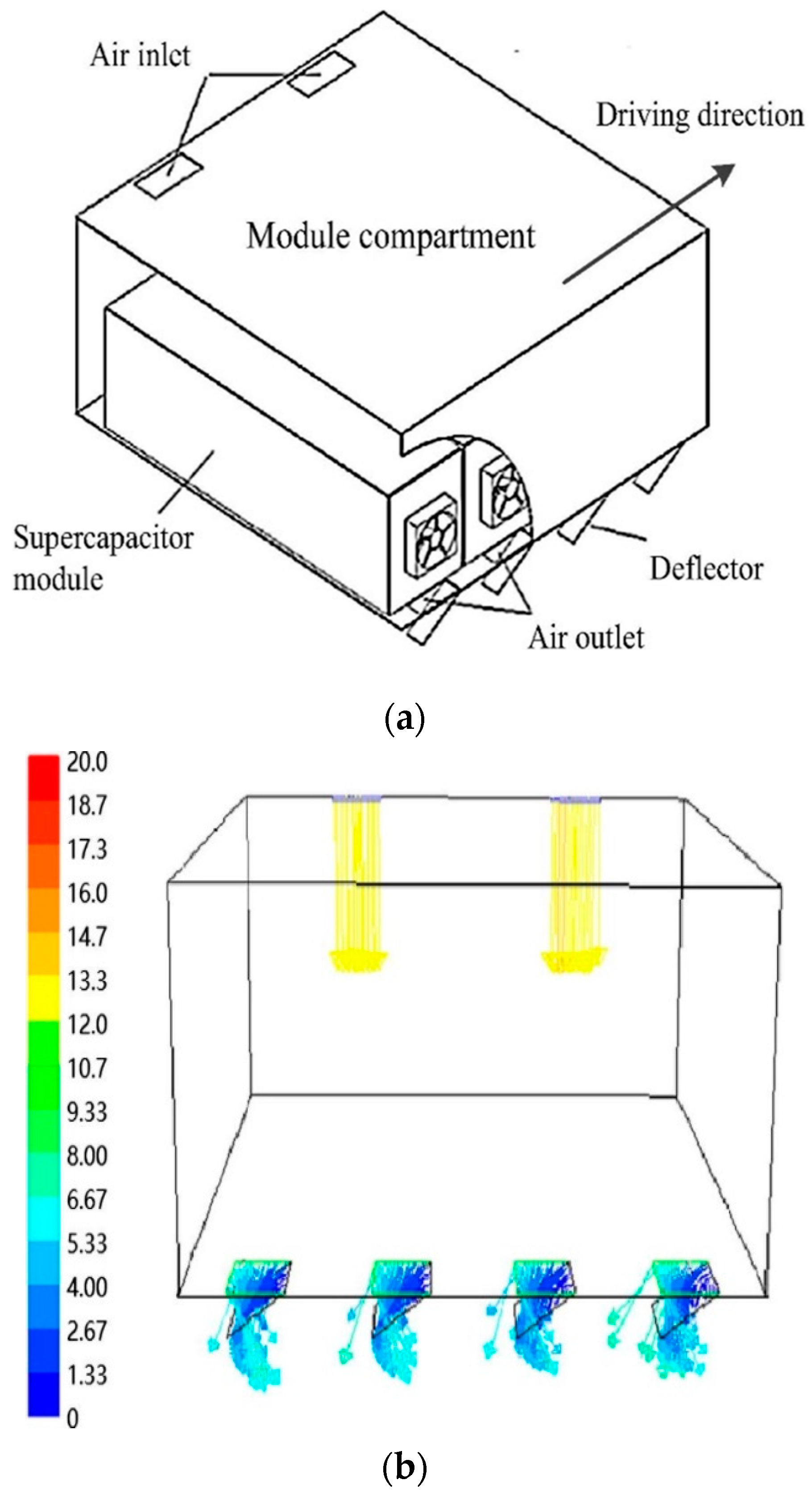
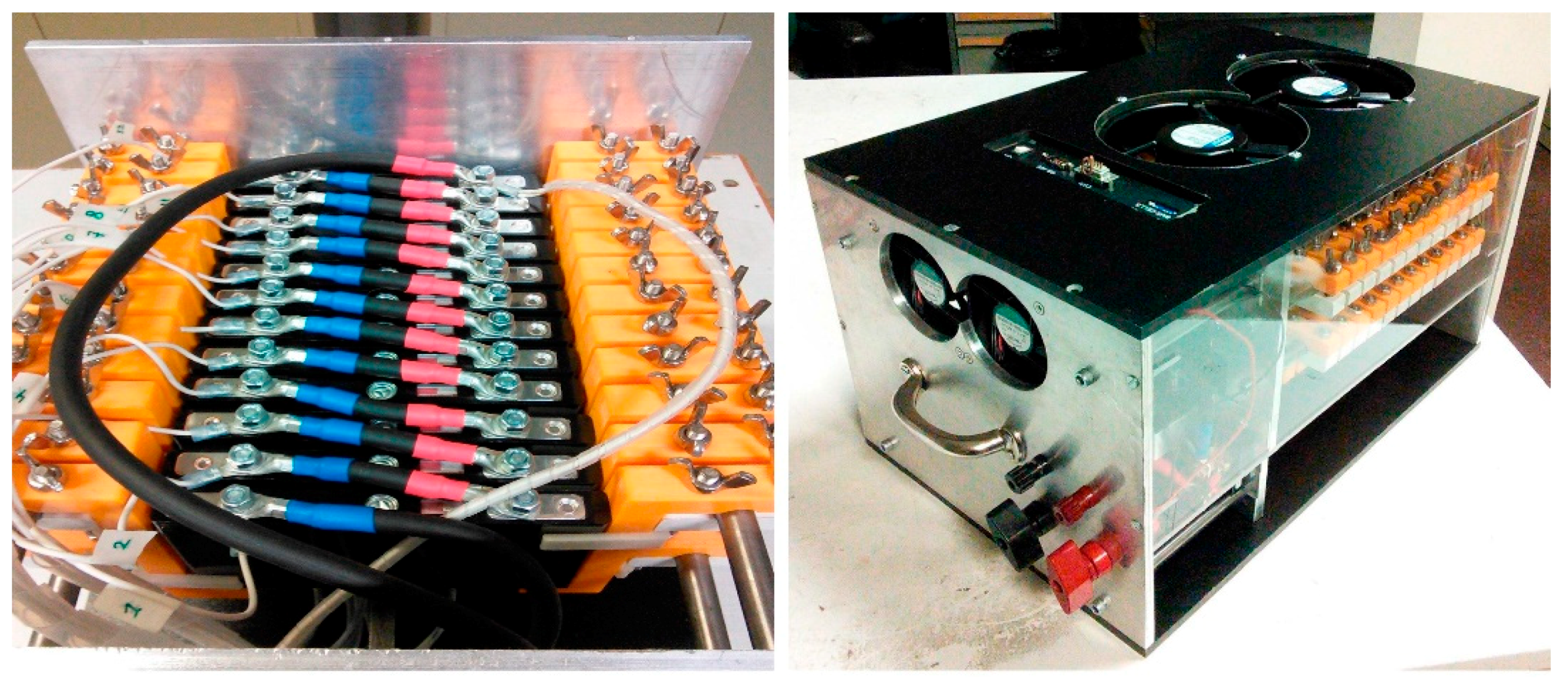
4.2. Air Cooling System
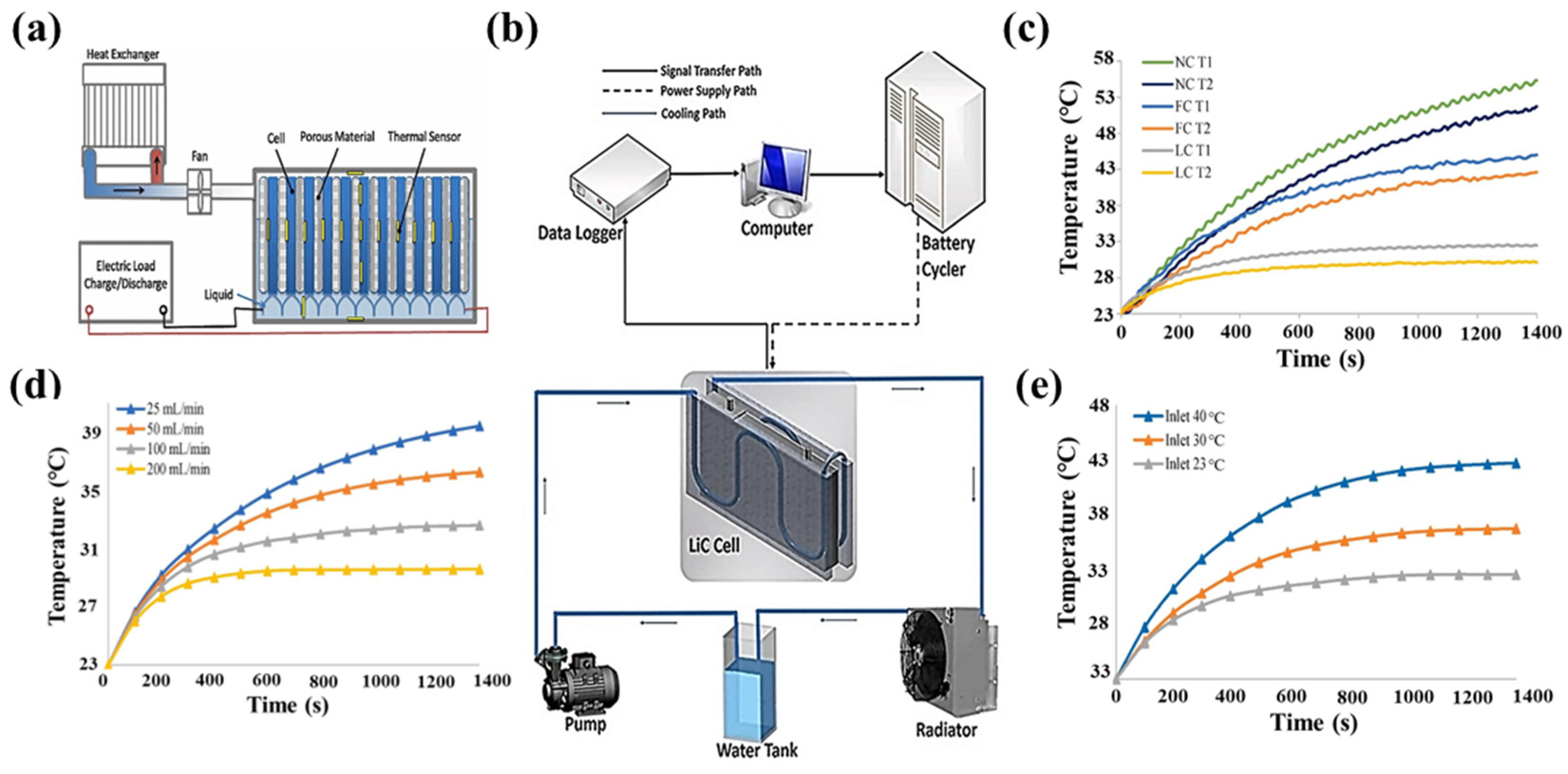
4.3. Liquid Cooling System
4.4. Phase Change Material Cooling System and Heat Pipe Cooling System
5. Discussion
6. Conclusions
- The working principle of SCs is not the same for various structures. The energy storage mechanism of EDLC is purely a physical process. Pseudocapacitors utilize redox reactions on the surface of the electrode material for the purpose of accumulating energy. LICs feature both electric double-layer energy storage and a faradaic reaction for energy storage.
- The temperature varies between various kinds of SCs during the charging and discharging process. Therefore, a series of models have been derived to account for temperature changes. For practical situations, the appropriate model is selected to compute the temperature distribution in accordance with accuracy and calculation time. In addition, SCs have been less studied in the area of thermal runaway, concentrating on thermal failure and overcharge/over-discharge and nail-penetration tests.
- Air cooling systems primarily employ airflow to alter capacitors’ surface temperature. The air flow rate is changed by additional devices, which influences heat dissipation. However, the forced air cooling system is constrained by the design of air ducts, which makes it impossible to guarantee temperature uniformity in capacitors. Liquid cooling systems require better sealing, where high demands are made on waterproofing, which is typically more complicated to devise than air cooling systems. In general, liquid cooling systems are relatively less researched in the field of SCs.
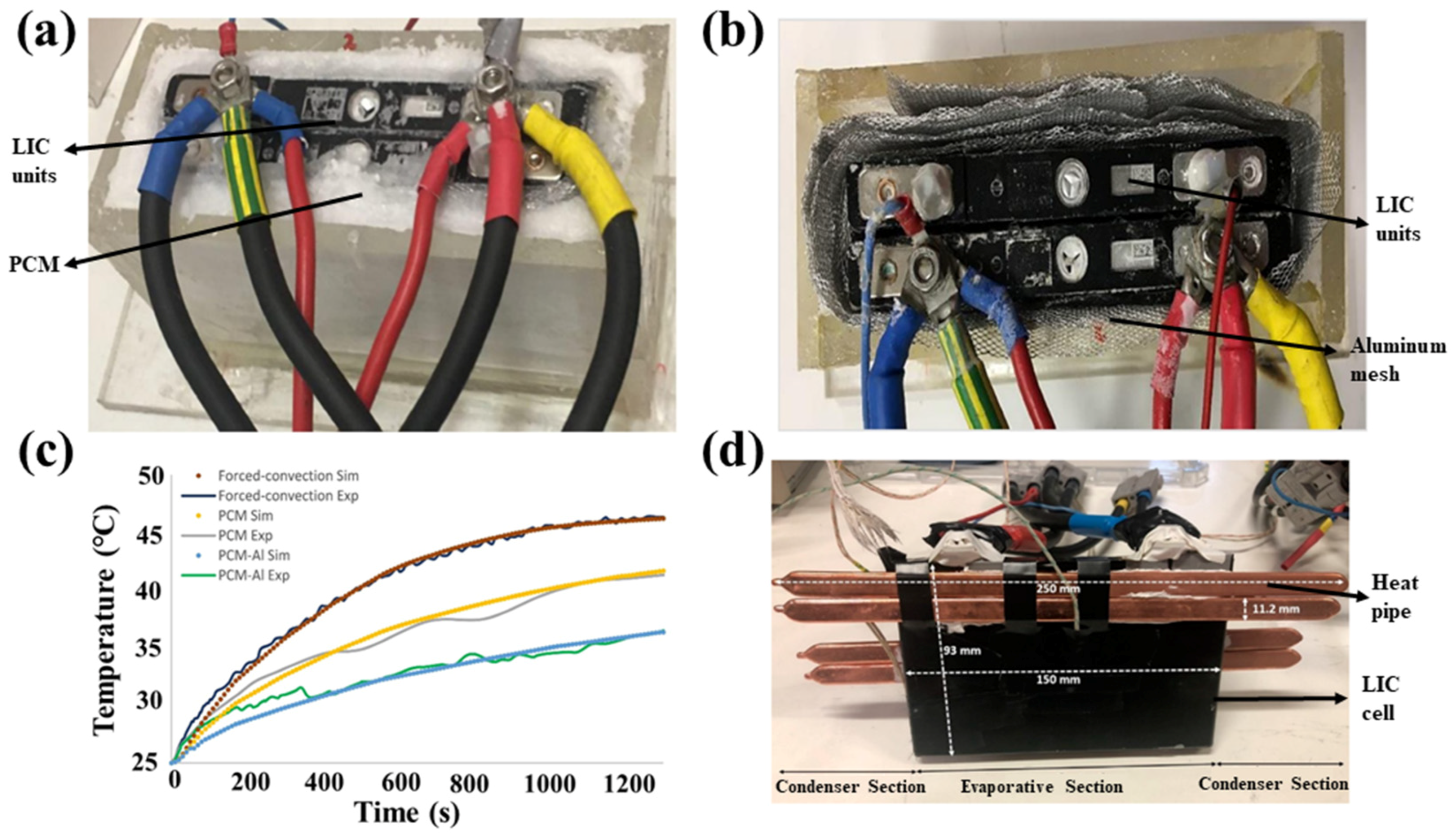
- PCMs do not require additional energy consumption, thus suppressing the temperature rise of capacitors. Nevertheless, the low thermal conductivity of materials proves to be a problem. By adding an aluminum mesh to the PCM for capacitors and combining it with other thermal management systems, the heat between components is better transferred so as to decrease the temperature of capacitors. Furthermore, with the rather new usage of heat pipes in thermal management systems, there is a need to further investigate the potential of integrating heat pipes with active or passive cooling systems.
Author Contributions
Funding
Institutional Review Board Statement
Informed Consent Statement
Data Availability Statement
Conflicts of Interest
References
- Lokhande, A.; Sharan, A.; Nair, S.S.; Shelke, A.; Karade, V.; Kim, J.H.; Singh, N.; Choi, D. Self-supported graphene oxide encapsulated chalcopyrite electrode for high-performance Li-ion capacitor. J. Energy Storage 2022, 55, 105791. [Google Scholar] [CrossRef]
- Kortekaas, L.; Fricke, S.; Korshunov, A.; Cekic-Laskovic, I.; Winter, M.; Grünebaum, M. Building Bridges: Unifying Design and Development Aspects for Advancing Non-Aqueous Redox-Flow Batteries. Batteries 2023, 9, 4. [Google Scholar] [CrossRef]
- Zhang, S.; Chen, W. Assessing the energy transition in China towards carbon neutrality with a probabilistic framework. Nat. Commun. 2022, 13, 87. [Google Scholar] [CrossRef]
- Zhang, X.; Sun, X.; An, Y.; Zhang, X.; Li, C.; Zhang, K.; Song, S.; Wang, K.; Ma, Y. Design of a fast-charge lithium-ion capacitor pack for automated guided vehicle. J. Energy Storage 2022, 48, 104045. [Google Scholar] [CrossRef]
- Ellabban, O.; Abu-Rub, H.; Blaabjerg, F. Renewable energy resources: Current status, future prospects and their enabling technology. Renew. Sustain. Energy Rev. 2014, 39, 748–764. [Google Scholar] [CrossRef]
- Chu, S.; Majumdar, A. Opportunities and challenges for a sustainable energy future. Nature 2012, 488, 294–303. [Google Scholar] [CrossRef]
- Li, J.; Ho, M.S.; Xie, C.; Stern, N. China’s flexibility challenge in achieving carbon neutrality by 2060. Renew. Sustain. Energy Rev. 2022, 158, 112112. [Google Scholar] [CrossRef]
- Adalati, R.; Sharma, M.; Sharma, S.; Kumar, A.; Malik, G.; Boukherroub, R.; Chandra, R. Metal nitrides as efficient electrode material for supercapacitors: A review. J. Energy Storage 2022, 56, 105912. [Google Scholar] [CrossRef]
- Ren, H.; Huang, C. Progress in electrode modification of fibrous supercapacitors. J. Energy Storage 2022, 56, 106032. [Google Scholar] [CrossRef]
- Shah, S.A.A.; Idrees, R.; Saeed, S. A critical review on polyimide derived carbon materials for high-performance supercapacitor electrodes. J. Energy Storage 2022, 55, 105667. [Google Scholar] [CrossRef]
- Sun, C.; Zhang, X.; Li, C.; Wang, K.; Sun, X.; Ma, Y. Recent advances in prelithiation materials and approaches for lithium-ion batteries and capacitors. Energy Storage Mater. 2020, 32, 497–516. [Google Scholar] [CrossRef]
- Zaulkiflee, N.D.; Ahmad, A.L.; Low, S.C.; Norikazu, N. Recent advances on the utilization of nanosheets as electrode material for supercapacitor application. J. Energy Storage 2022, 55, 105697. [Google Scholar] [CrossRef]
- Pomerantseva, E.; Bonaccorso, F.; Feng, X.; Cui, Y.; Gogotsi, Y. Energy storage: The future enabled by nanomaterials. Science 2019, 366, 969. [Google Scholar] [CrossRef]
- Zheng, W.; Li, Z.; Han, G.; Zhao, Q.; Lu, G.; Hu, X.; Sun, J.; Wang, R.; Xu, C. Nitrogen-doped activated porous carbon for 4.5 V lithium-ion capacitor with high energy and power density. J. Energy Storage 2022, 47, 103675. [Google Scholar] [CrossRef]
- Sharma, P.; Bora, B.J. A Review of Modern Machine Learning Techniques in the Prediction of Remaining Useful Life of Lithium-Ion Batteries. Batteries 2023, 9, 13. [Google Scholar] [CrossRef]
- Sun, C.; Zhang, X.; An, Y.; Li, C.; Zhang, X.; Zhang, H.; Sun, X.; Wang, K.; Geng, J.; Ma, Y. Molecularly chemical prelithiation of soft carbon towards high-performance lithium-ion capacitors. J. Energy Storage 2022, 56, 106009. [Google Scholar] [CrossRef]
- Benavides, D.; Arévalo, P.; Tostado-Véliz, M.; Vera, D.; Escamez, A.; Aguado, J.A.; Jurado, F. An Experimental Study of Power Smoothing Methods to Reduce Renewable Sources Fluctuations Using Supercapacitors and Lithium-Ion Batteries. Batteries 2022, 8, 228. [Google Scholar] [CrossRef]
- Akkinepally, B.; Reddy, I.N.; Manjunath, V.; Reddy, M.V.; Mishra, Y.K.; Ko, T.J.; Zaghib, K.; Shim, J. Temperature effect and kinetics, LiZr2(PO4)3 and Li1.2Al0.2Zr1.8(PO4)3 and electrochemical properties for rechargeable ion batteries. Int. J. Energy. Res. 2022, 46, 14116–14132. [Google Scholar] [CrossRef]
- Peng, H.; Wang, H.; Wang, Y.; Wang, X.; Chen, S.; Yan, B. Achieving a highly safe supercapacitor via the combination of a temperature-responsive hydrogel-electrolyte and electrochromic electrodes. J. Mater. Chem. A 2022, 10, 20302–20311. [Google Scholar] [CrossRef]
- Akkinepally, B.; Reddy, I.N.; Lee, C.; Ko, T.J.; Rao, P.S.; Shim, J. Promising electrode material of Fe3O4 nanoparticles decorated on V2O5 nanobelts for high-performance symmetric supercapacitors. Ceram. Int. 2023, 49, 6280–6288. [Google Scholar] [CrossRef]
- Rafik, F.; Gualous, H.; Gallay, R.; Crausaz, A.; Berthon, A. Frequency, thermal and voltage supercapacitor characterization and modeling. J. Power Sources 2007, 165, 928–934. [Google Scholar] [CrossRef]
- Sun, X.; Zhang, X.; Wang, K.; Xu, N.; Ma, Y. Temperature effect on electrochemical performances of Li-ion hybrid capacitors. J. Solid State Electrochem. 2015, 19, 2501–2506. [Google Scholar] [CrossRef]
- Yang, H.; Leow, W.R.; Chen, X. Thermal-Responsive Polymers for Enhancing Safety of Electrochemical Storage Devices. Adv. Mater. 2018, 30, e1704347. [Google Scholar] [CrossRef] [PubMed]
- Li, Q.; Chen, L.; Gadinski, M.R.; Zhang, S.; Zhang, G.; Li, U.; Iagodkine, E.; Haque, A.; Chen, L.Q.; Jackson, N.; et al. Flexible high-temperature dielectric materials from polymer nanocomposites. Nature 2015, 523, 576–579. [Google Scholar] [CrossRef] [PubMed]
- Zhang, J.; Wang, J.; Shi, Z.; Xu, Z. Electrochemical behavior of lithium ion capacitor under low temperature. J. Electroanal. Chem. 2018, 817, 195–201. [Google Scholar] [CrossRef]
- Fly, A.; Kirkpatrick, I.; Chen, R. Low temperature performance evaluation of electrochemical energy storage technologies. Appl. Therm. Eng. 2021, 189, 116750. [Google Scholar] [CrossRef]
- Zhang, X.; Wang, W.; He, H.; Hua, L.; Heng, J. Optimization of the air-cooled supercapacitor module compartment for an electric bus. Appl. Therm. Eng. 2017, 112, 1297–1304. [Google Scholar] [CrossRef]
- Lai, X.; Yao, J.; Jin, C.; Feng, X.; Wang, H.; Xu, C.; Zheng, Y. A Review of Lithium-Ion Battery Failure Hazards: Test Standards, Accident Analysis, and Safety Suggestions. Batteries 2022, 8, 248. [Google Scholar] [CrossRef]
- Voicu, I.; Louahlia, H.; Gualous, H.; Gallay, R. Thermal management and forced air-cooling of supercapacitors stack. Appl. Therm. Eng. 2015, 85, 89–99. [Google Scholar] [CrossRef]
- Widyantara, R.D.; Zulaikah, S.; Juangsa, F.B.; Budiman, B.A.; Aziz, M. Review on Battery Packing Design Strategies for Superior Thermal Management in Electric Vehicles. Batteries 2022, 8, 287. [Google Scholar] [CrossRef]
- Stettner, T.; Balducci, A. Protic ionic liquids in energy storage devices: Past, present and future perspective. Energy Storage Mater. 2021, 40, 402–414. [Google Scholar] [CrossRef]
- Chen, Y.; Wang, M.; Zhang, J.; Tu, J.; Ge, J.; Jiao, S. Green and sustainable molten salt electrochemistry for the conversion of secondary carbon pollutants to advanced carbon materials. J. Mater. Chem. A 2021, 9, 14119–14146. [Google Scholar] [CrossRef]
- Zhang, L.; Hu, X.; Wang, Z.; Sun, F.; Dorrell, D.G. A review of supercapacitor modeling, estimation, and applications: A control/management perspective. Renew. Sustain. Energy Rev. 2018, 81, 1868–1878. [Google Scholar] [CrossRef]
- Zou, C.; Zhang, L.; Hu, X.; Wang, Z.; Wik, T.; Pecht, M. A review of fractional-order techniques applied to lithium-ion batteries, lead-acid batteries, and supercapacitors. J. Power Sources 2018, 390, 286–296. [Google Scholar] [CrossRef]
- Muzaffar, A.; Ahamed, M.B.; Deshmukh, K.; Thirumalai, J. A review on recent advances in hybrid supercapacitors: Design, fabrication and applications. Renew. Sustain. Energy Rev. 2019, 101, 123–145. [Google Scholar] [CrossRef]
- Lin, X.; Salari, M.; Arava, L.M.; Ajayan, P.M.; Grinstaff, M.W. High temperature electrical energy storage: Advances, challenges, and frontiers. Chem. Soc. Rev. 2016, 45, 5848–5887. [Google Scholar] [CrossRef]
- Liu, S.; Wei, L.; Wang, H. Review on reliability of supercapacitors in energy storage applications. Appl. Energy 2020, 278, 115436. [Google Scholar] [CrossRef]
- Roy, B.K.; Tahmid, I.; Rashid, T.U. Chitosan-based materials for supercapacitor applications: A review. J. Mater. Chem. A 2021, 9, 17592–17642. [Google Scholar] [CrossRef]
- Kumar, S.; Nehra, M.; Kedia, D.; Dilbaghi, N.; Tankeshwar, K.; Kim, K.-H. Carbon nanotubes: A potential material for energy conversion and storage. Prog. Energy Combust. Sci. 2018, 64, 219–253. [Google Scholar] [CrossRef]
- Al Sakka, M.; Gualous, H.; Van Mierlo, J.; Culcu, H. Thermal modeling and heat management of supercapacitor modules for vehicle applications. J. Power Sources 2009, 194, 581–587. [Google Scholar] [CrossRef]
- Naseri, F.; Karimi, S.; Farjah, E.; Schaltz, E. Supercapacitor management system: A comprehensive review of modeling, estimation, balancing, and protection techniques. Renew. Sustain. Energy Rev. 2022, 155, 111913. [Google Scholar] [CrossRef]
- Rashidi, S.; Karimi, N.; Sunden, B.; Kim, K.C.; Olabi, A.G.; Mahian, O. Progress and challenges on the thermal management of electrochemical energy conversion and storage technologies: Fuel cells, electrolysers, and supercapacitors. Prog. Energy Combust. Sci. 2022, 88, 100966. [Google Scholar] [CrossRef]
- Sharma, P.; Bhatti, T.S. A review on electrochemical double-layer capacitors. Energy Convers. Manag. 2010, 51, 2901–2912. [Google Scholar] [CrossRef]
- Wei, L.; Wu, M.; Yan, M.; Liu, S.; Cao, Q.; Wang, H. A Review on Electrothermal Modeling of Supercapacitors for Energy Storage Applications. IEEE Trans. Emerg. Sel. Top. Power Electron. 2019, 7, 1677–1690. [Google Scholar] [CrossRef]
- Pal, B.; Yang, S.; Ramesh, S.; Thangadurai, V.; Jose, R. Electrolyte selection for supercapacitive devices: A critical review. Nanoscale Adv. 2019, 1, 3807. [Google Scholar] [CrossRef]
- Pothu, R.; Bolagam, R.; Wang, Q.-H.; Ni, W.; Cai, J.-F.; Peng, X.-X.; Feng, Y.-Z.; Ma, J.-M. Nickel sulfide-based energy storage materials for high-performance electrochemical capacitors. Rare Met. 2021, 40, 353–373. [Google Scholar] [CrossRef]
- Beguin, F.; Presser, V.; Balducci, A.; Frackowiak, E. Carbons and electrolytes for advanced supercapacitors. Adv. Mater. 2014, 26, 2219–2251. [Google Scholar] [CrossRef]
- Wang, G.; Zhang, L.; Zhang, J. A review of electrode materials for electrochemical supercapacitors. Chem. Soc. Rev. 2012, 41, 797–828. [Google Scholar] [CrossRef] [PubMed]
- Dubal, D.P.; Ayyad, O.; Ruiz, V.; Gomez-Romero, P. Hybrid energy storage: The merging of battery and supercapacitor chemistries. Chem. Soc. Rev. 2015, 44, 1777. [Google Scholar] [CrossRef]
- Simon, P.; Gogotsi, Y. Materials for electrochemical capacitors. Nat. Mater. 2008, 7, 845–854. [Google Scholar]
- Zhang, L.L.; Zhao, X.S. Carbon-based materials as supercapacitor electrodes. Chem. Soc. Rev. 2009, 38, 2520–2531. [Google Scholar] [CrossRef]
- Li, C.; Zhang, X.; Wang, K.; Su, F.; Chen, C.; Liu, F.; Wu, Z.-S.; Ma, Y. Recent advances in carbon nanostructures prepared from carbon dioxide for high-performance supercapacitors. J. Energy Chem. 2021, 54, 352–367. [Google Scholar] [CrossRef]
- Xiong, G.; He, P.; Huang, B.; Chen, T.; Bo, Z.; Fisher, T.S. Graphene nanopetal wire supercapacitors with high energy density and thermal durability. Nano Energy 2017, 38, 127–136. [Google Scholar] [CrossRef]
- Li, C.; Zhang, X.; Lv, Z.; Wang, K.; Sun, X.; Chen, X.; Ma, Y. Scalable combustion synthesis of graphene-welded activated carbon for high-performance supercapacitors. Chem. Eng. J. 2021, 414, 128781. [Google Scholar] [CrossRef]
- Zhao, Z.; Xia, K.; Hou, Y.; Zhang, Q.; Ye, Z.; Lu, J. Designing flexible, smart and self-sustainable supercapacitors for portable/wearable electronics: From conductive polymers. Chem. Soc. Rev. 2021, 50, 12702–12743. [Google Scholar] [CrossRef]
- Liu, X.; Xu, W.; Zheng, D.; Li, Z.; Zeng, Y.; Lu, X. Carbon cloth as an advanced electrode material for supercapacitors: Progress and challenges. J. Mater. Chem. A 2020, 8, 17938–17950. [Google Scholar] [CrossRef]
- Wang, C.; Muni, M.; Strauss, V.; Borenstein, A.; Chang, X.; Huang, A.; Qu, S.; Sung, K.; Gilham, T.; Kaner, R.B. Graphene’s Role in Emerging Trends of Capacitive Energy Storage. Small 2021, 17, e2006875. [Google Scholar] [CrossRef]
- Nakhanivej, P.; Rana, H.H.; Kim, H.; Xia, B.Y.; Park, H.S. Transport and Durability of Energy Storage Materials Operating at High Temperatures. ACS Nano 2020, 14, 7696–7703. [Google Scholar] [CrossRef]
- Shao, Y.; El-Kady, M.F.; Sun, J.; Li, Y.; Zhang, Q.; Zhu, M.; Wang, H.; Dunn, B.; Kaner, R.B. Design and Mechanisms of Asymmetric Supercapacitors. Chem. Rev. 2018, 118, 9233–9280. [Google Scholar] [CrossRef]
- Lukatskaya, M.R.; Kota, S.; Lin, Z.; Zhao, M.-Q.; Shpigel, N.; Levi, M.D.; Halim, J.; Taberna, P.-L.; Barsoum, M.W.; Simon, P.; et al. Ultra-high-rate pseudocapacitive energy storage in two-dimensional transition metal carbides. Nat. Energy 2017, 2, 17105. [Google Scholar] [CrossRef]
- Conway, B.E.; Birss, V.; Wojtowicz, J. The role and utilization of pseudocapacitance for energy storage by supercapacitors. J. Power Sources 1997, 66, 1–14. [Google Scholar] [CrossRef]
- Wang, F.; Wu, X.; Yuan, X.; Liu, Z.; Zhang, Y.; Fu, L.; Zhu, Y.; Zhou, Q.; Wu, Y.; Huang, W. Latest advances in supercapacitors: From new electrode materials to novel device designs. Chem. Soc. Rev. 2017, 46, 6816–6854. [Google Scholar] [CrossRef] [PubMed]
- Augustyn, V.; Simon, P.; Dunn, B. Pseudocapacitive oxide materials for high-rate electrochemical energy storage. Energy Environ. Sci. 2014, 7, 1597. [Google Scholar] [CrossRef]
- Makino, S.; Ban, T.; Sugimoto, W. Towards Implantable Bio-Supercapacitors: Pseudocapacitance of Ruthenium Oxide Nanoparticles and Nanosheets in Acids, Buffered Solutions, and Bioelectrolytes. J. Electrochem. Soc. 2015, 162, A5001–A5006. [Google Scholar] [CrossRef]
- Yu, F.; Pang, L.; Wang, H.-X. Preparation of mulberry-like RuO2 electrode material for supercapacitors. Rare Met. 2021, 40, 440–447. [Google Scholar] [CrossRef]
- Bhattacharya, S.; Roy, I.; Tice, A.; Chapman, C.; Udangawa, R.; Chakrapani, V.; Plawsky, J.L.; Linhardt, R.J. High-Conductivity and High-Capacitance Electrospun Fibers for Supercapacitor Applications. ACS Appl. Mater. Interfaces 2020, 12, 19369–19376. [Google Scholar] [CrossRef]
- Kim, J.W.; Augustyn, V.; Dunn, B. The Effect of Crystallinity on the Rapid Pseudocapacitive Response of Nb2O5. Adv. Energy Mater. 2012, 2, 141–148. [Google Scholar] [CrossRef]
- Yue, T.; Shen, B.; Gao, P. Carbon material/MnO2 as conductive skeleton for supercapacitor electrode material: A review. Renew. Sustain. Energy Rev. 2022, 158, 112131. [Google Scholar] [CrossRef]
- Salanne, M.; Rotenberg, B.; Naoi, K.; Kaneko, K.; Taberna, P.L.; Grey, C.P.; Dunn, B.; Simon, P. Efficient storage mechanisms for building better supercapacitors. Nat. Energy 2016, 1, 16070. [Google Scholar] [CrossRef]
- Li, B.; Zheng, J.; Zhang, H.; Jin, L.; Yang, D.; Lv, H.; Shen, C.; Shellikeri, A.; Zheng, Y.; Gong, R.; et al. Electrode Materials, Electrolytes, and Challenges in Nonaqueous Lithium-Ion Capacitors. Adv. Mater. 2018, 30, 1705670. [Google Scholar] [CrossRef]
- Jezowski, P.; Crosnier, O.; Deunf, E.; Poizot, P.; Beguin, F.; Brousse, T. Safe and recyclable lithium-ion capacitors using sacrificial organic lithium salt. Nat. Mater. 2018, 17, 167–173. [Google Scholar] [CrossRef]
- Zhang, X.; Wang, L.; Liu, W.; Li, C.; Wang, K.; Ma, Y. Recent Advances in MXenes for Lithium-Ion Capacitors. Acs Omega 2020, 5, 75–82. [Google Scholar] [CrossRef] [PubMed]
- Wang, P.-L.; Sun, X.-Z.; An, Y.-B.; Zhang, X.; Yuan, C.-Z.; Zheng, S.-H.; Wang, K.; Ma, Y.-W. Additives to propylene carbonate-based electrolytes for lithium-ion capacitors. Rare Met. 2022, 41, 1304–1313. [Google Scholar] [CrossRef]
- Shellikeri, A.; Hung, I.; Gan, Z.; Zheng, J. In Situ NMR Tracks Real-Time Li Ion Movement in Hybrid Supercapacitor–Battery Device. J. Phys. Chem. C 2016, 120, 6314–6323. [Google Scholar] [CrossRef]
- Ghossein, N.E.; Sari, A.; Venet, P. Effects of the Hybrid Composition of Commercial Lithium-Ion Capacitors on Their Floating Aging. IEEE Trans. Power Electron. 2019, 34, 2292. [Google Scholar] [CrossRef]
- Sun, X.; Wang, P.; An, Y.; Zhang, X.; Zheng, S.; Wang, K.; Ma, Y. A Fast and Scalable Pre-Lithiation Approach for Practical Large-Capacity Lithium-Ion Capacitors. J. Electrochem. Soc. 2021, 168, 110540. [Google Scholar] [CrossRef]
- Jin, L.; Shen, C.; Shellikeri, A.; Wu, Q.; Zheng, J.; Andrei, P.; Zhang, J.-G.; Zheng, J.P. Progress and perspectives on pre-lithiation technologies for lithium ion capacitors. Energy Environ. Sci. 2020, 13, 2341–2362. [Google Scholar] [CrossRef]
- Yi, S.; Wang, L.; Zhang, X.; Li, C.; Liu, W.; Wang, K.; Sun, X.; Xu, Y.; Yang, Z.; Cao, Y.; et al. Cationic intermediates assisted self-assembly two-dimensional Ti3C2Tx/rGO hybrid nanoflakes for advanced lithium-ion capacitors. Sci. Bull. 2021, 66, 914–924. [Google Scholar] [CrossRef] [PubMed]
- Sun, X.; Geng, L.; Yi, S.; Li, C.; An, Y.; Zhang, X.; Zhang, X.; Wang, K.; Ma, Y. Effects of carbon black on the electrochemical performances of SiOx anode for lithium-ion capacitors. J. Power Sources 2021, 499, 229936. [Google Scholar] [CrossRef]
- Sun, C.; Zhang, X.; Li, C.; Wang, K.; Sun, X.; Ma, Y. A presodiation strategy with high efficiency by utilizing low-price and eco-friendly Na2CO3 as the sacrificial salt towards high-performance pouch sodium-ion capacitors. J. Power Sources 2021, 515, 230628. [Google Scholar] [CrossRef]
- Zhang, J.; Wu, H.; Wang, J.; Shi, J.; Shi, Z. Pre-lithiation design and lithium ion intercalation plateaus utilization of mesocarbon microbeads anode for lithium-ion capacitors. Electrochim. Acta 2015, 182, 156–164. [Google Scholar] [CrossRef]
- Olabi, A.G.; Abbas, Q.; Makky, A.A.; Abdelkareem, M.A. Supercapacitors as next generation energy storage devices: Properties and applications. Energy 2022, 248, 123617. [Google Scholar] [CrossRef]
- Miller, J.R. Electrochemical capacitor thermal management issues at high-rate cycling. Electrochim. Acta 2006, 52, 1703–1708. [Google Scholar] [CrossRef]
- Zhang, X.; Zhang, X.; Sun, X.; An, Y.; Song, S.; Li, C.; Wang, K.; Su, F.; Chen, C.-M.; Liu, F.; et al. Electrochemical impedance spectroscopy study of lithium-ion capacitors: Modeling and capacity fading mechanism. J. Power Sources 2021, 488, 229454. [Google Scholar] [CrossRef]
- Kötz, R.; Hahna, M.; Gallay, R. Temperature behavior and impedance fundamentals of supercapacitors. J. Power Sources 2006, 154, 550–555. [Google Scholar] [CrossRef]
- Gualous, H.; Bouquain, D.; Berthon, A.; Kauffmann, J.M. Experimental study of supercapacitor serial resistance and capacitance variations with temperature. J. Power Sources 2003, 123, 86–93. [Google Scholar] [CrossRef]
- Gualous, H.; Louahlia-Gualous, H.; Gallay, R.; Miraoui, A. Supercapacitor Thermal Modeling and Characterization in Transient State for Industrial Applications. IEEE Trans. Ind. Appl. 2009, 45, 1035–1044. [Google Scholar] [CrossRef]
- Parka, S.; Kang, S.-W.; Kima, K. Competition between ionic adsorption and desorption on electrochemical double layer capacitor electrodes in acetonitrile solutions at different currents and temperatures. J. Power Sources 2017, 372, 8–15. [Google Scholar] [CrossRef]
- Hahna, M.; Kötz, R.; Gallay, R.; Siggel, A. Pressure evolution in propylene carbonate based electrochemical double layer capacitors. Electrochim. Acta 2006, 52, 1709–1712. [Google Scholar] [CrossRef]
- Liu, W.; Zhang, X.; Li, C.; Wang, K.; Sun, X.; Ma, Y. Carbon-coated Li3VO4 with optimized structure as high capacity anode material for lithium-ion capacitors. Chin. Chem. Lett. 2020, 31, 2225–2229. [Google Scholar] [CrossRef]
- Bittner, A.M.; Zhu, M.; Yang, Y.; Waibel, H.F.; Konuma, M.; Starke, U.; Weber, C.J. Ageing of electrochemical double layer capacitors. J. Power Sources 2012, 203, 262–273. [Google Scholar] [CrossRef]
- Song, S.; Zhang, X.; Li, C.; Wang, K.; Sun, X.; Ma, Y. Anomalous diffusion models in frequency-domain characterization of lithium-ion capacitors. J. Power Sources 2021, 490, 229332. [Google Scholar] [CrossRef]
- Dandeville, Y.; Guillemet, P.; Scudeller, Y.; Crosnier, O.; Athouel, L.; Brousse, T. Measuring time-dependent heat profiles of aqueous electrochemical capacitors under cycling. Thermochim. Acta 2011, 526, 1–8. [Google Scholar] [CrossRef]
- Pascot, C.; Dandeville, Y.; Scudeller, Y.; Guillemet, P.; Brousse, T. Calorimetric measurement of the heat generated by a Double-Layer Capacitor cell under cycling. Thermochim. Acta 2010, 510, 53–60. [Google Scholar] [CrossRef]
- Zhang, Y.; Liu, Z.; Sun, X.; An, Y.; Zhang, X.; Wang, K.; Dong, C.; Huo, Q.; Wei, T.; Ma, Y. Experimental study of thermal charge–discharge behaviors of pouch lithium-ion capacitors. J. Energy Storage 2019, 25, 100902. [Google Scholar] [CrossRef]
- Bo, Z.; Li, H.; Yang, H.; Li, C.; Wu, S.; Xu, C.; Xiong, G.; Mariotti, D.; Yan, J.; Cen, K.; et al. Combinatorial atomistic-to-AI prediction and experimental validation of heating effects in 350 F supercapacitor modules. Int. J. Heat Mass Transf. 2021, 171, 121075. [Google Scholar] [CrossRef]
- Li, H.; Yang, H.; Yan, J.; Cen, K.; Ostrikov, K.K.; Bo, Z. Energy and entropy generation analysis in a supercapacitor for different operating conditions. Energy 2022, 260, 124932. [Google Scholar] [CrossRef]
- Zhang, X.; Wang, W.; Lua, J.; Hu, L.; Heng, J. Reversible heat of electric double-layer capacitors during galvanostatic charging and discharging cycles. Thermochim. Acta 2016, 636, 1–10. [Google Scholar] [CrossRef]
- Parvini, Y.; Siegel, J.B.; Stefanopoulou, A.G.; Vahidi, A. Supercapacitor Electrical and Thermal Modeling, Identification, and Validation for a Wide Range of Temperature and Power Applications. IEEE Trans. Ind. Electron. 2016, 63, 1574–1585. [Google Scholar] [CrossRef]
- Lee, J.; Yi, J.; Kim, D.; Shin, C.; Min, K.-S.; Choi, J.; Lee, H.-Y. Modeling of the Electrical and Thermal Behaviors of an Ultracapacitor. Energies 2014, 7, 8264–8278. [Google Scholar] [CrossRef]
- Schiffer, J.; Linzen, D.; Sauer, D.U. Heat generation in double layer capacitors. J. Power Sources 2006, 160, 765–772. [Google Scholar] [CrossRef]
- d’Entremont, A.; Pilon, L. Scaling laws for heat generation and temperature oscillations in EDLCs under galvanostatic cycling. Int. J. Heat Mass Transf. 2014, 75, 637–649. [Google Scholar] [CrossRef]
- d’Entremont, A.L.; Pilon, L. Thermal effects of asymmetric electrolytes in electric double layer capacitors. J. Power Sources 2015, 273, 196–209. [Google Scholar] [CrossRef]
- Kundu, A.; Pilon, L.; Fisher, T.S. A continuum model of heat transfer in electrical double-layer capacitors with porous electrodes under constant-current cycling. J. Power Sources 2021, 511, 230404. [Google Scholar] [CrossRef]
- Xu, T.; Du, H.; Liu, H.; Liu, W.; Zhang, X.; Si, C.; Liu, P.; Zhang, K. Advanced Nanocellulose-Based Composites for Flexible Functional Energy Storage Devices. Adv. Mater. 2021, 33, e2101368. [Google Scholar] [CrossRef]
- d’Entremont, A.; Pilon, L. First-principles thermal modeling of electric double layer capacitors under constant-current cycling. J. Power Sources 2014, 246, 887–898. [Google Scholar] [CrossRef]
- d’Entremont, A.; Pilon, L. First-order thermal model of commercial EDLCs. Appl. Therm. Eng. 2014, 67, 439–446. [Google Scholar] [CrossRef]
- d’Entremont, A.L.; Pilon, L. First-principles thermal modeling of hybrid pseudocapacitors under galvanostatic cycling. J. Power Sources 2016, 335, 172–188. [Google Scholar] [CrossRef]
- Soltani, M.; Beheshti, S.H. A comprehensive review of lithium ion capacitor: Development, modelling, thermal management and applications. J. Energy Storage 2021, 34, 102019. [Google Scholar] [CrossRef]
- Berckmans, G.; Ronsmans, J.; Jaguemont, J.; Samba, A.; Omar, N.; Hegazy, O.; Soltani, M.; Firouz, Y.; Bossche, P.v.d. Lithium-ion capacitor: Analysis of thermal behavior and development of three-dimensional thermal model. J. Electrochem. Energy Conv. Stor. 2017, 14, 041005. [Google Scholar] [CrossRef]
- Bernardi, D.; Pawlikowski, E.; Newman, J. A General Energy Balance for Battery Systems. J. Electrochem. Soc. 1985, 132, 5–12. [Google Scholar] [CrossRef] [Green Version]
- Zhou, W.; Liu, Z.; An, Y.; Luo, M.; Zhang, X.; Song, S.; Li, C.; Liu, Z.; Gao, Y.; Zhang, H.; et al. Thermal behavior analysis of lithium-ion capacitors at transient high discharge rate. J. Energy Storage 2022, 53, 105208. [Google Scholar] [CrossRef]
- Miller, M.; Baltes, N.T.M.; Rabenecker, P.M.; Hagen, M.W.; Tübke, J. Comprehensive determination of heat generation and thermal modelling of a hybrid capacitor. J. Power Sources 2019, 435, 226752. [Google Scholar] [CrossRef]
- Likitchatchawankun, A.; Whang, G.; Lau, J.; Munteshari, O.; Dunn, B.; Pilon, L. Effect of temperature on irreversible and reversible heat generation rates in ionic liquid-based electric double layer capacitors. Electrochim. Acta 2020, 338, 135802. [Google Scholar] [CrossRef]
- Munteshari, O.; Lau, J.; Krishnan, A.; Dunn, B.; Pilon, L. Isothermal calorimeter for measurements of time-dependent heat generation rate in individual supercapacitor electrodes. J. Power Sources 2018, 374, 257–268. [Google Scholar] [CrossRef]
- Munteshari, O.; Lau, J.; Ashby, D.S.; Dunn, B.; Pilon, L. Effects of Constituent Materials on Heat Generation in Individual EDLC Electrodes. J. Electrochem. Soc. 2018, 165, A1547–A1557. [Google Scholar] [CrossRef]
- Gualous, H.; Louahlia, H.; Gallay, R. Supercapacitor Characterization and Thermal Modelling With Reversible and Irreversible Heat Effect. IEEE Trans. Power Electron. 2011, 26, 3402–3409. [Google Scholar] [CrossRef]
- Frivaldsky, M.; Cuntala, J.; Spanik, P.; Kanovsky, A. Investigation of thermal effects and lifetime estimation of electrolytic double layer capacitors during repeated charge and discharge cycles in dedicated application. Electr. Eng. 2018, 100, 11–25. [Google Scholar] [CrossRef]
- Robinson, J.B.; Shearing, P.R.; Brett, D.J.L. Thermal Imaging of Electrochemical Power Systems: A Review. J. Imaging 2016, 2, 2. [Google Scholar] [CrossRef]
- Fletcher, S.I.; Sillars, F.B.; Carter, R.C.; Cruden, A.J.; Mirzaeian, M.; Hudson, N.E.; Parkinson, J.A.; Hall, P.J. The effects of temperature on the performance of electrochemical double layer capacitors. J. Power Sources 2010, 195, 7484–7488. [Google Scholar] [CrossRef]
- Soltani, M.; Sutter, L.D.; Ronsmans, J.; Mierlo, J.v. A high current electro-thermal model for lithium-ion capacitor technology in a wide temperature range. J. Energy Storage 2020, 31, 101624. [Google Scholar] [CrossRef]
- Kreczanik, P.; Venet, P.; Hijazi, A.; Clerc, G. Study of Supercapacitor Aging and Lifetime Estimation According to Voltage, Temperature, and RMS Current. IEEE Trans. Ind. Electron. 2014, 61, 4895–4902. [Google Scholar] [CrossRef]
- Lystianingrum, V.; Hredzak, B.; Agelidis, V.G.; Djanali, V.S. On Estimating Instantaneous Temperature of a Supercapacitor String Using an Observer Based on Experimentally Validated Lumped Thermal Model. IEEE Trans. Energy Convers. 2015, 30, 1438–1448. [Google Scholar] [CrossRef]
- Berrueta, A.; San Martín, I.; Hernández, A.; Ursúa, A.; Sanchis, P. Electro-thermal modelling of a supercapacitor and experimental validation. J. Power Sources 2014, 259, 154–165. [Google Scholar] [CrossRef]
- Sarwar, W.; Marinescu, M.; Green, N.; Taylor, N.; Offer, G. Electrochemical double layer capacitor electro-thermal modelling. J. Energy Storage 2016, 5, 10–24. [Google Scholar] [CrossRef]
- Kashkooli, A.G.; Farhad, S.; Chabot, V.; Yu, A.; Chen, Z. Effects of structural design on the performance of electrical double layer capacitors. Appl. Energy 2015, 138, 631–639. [Google Scholar] [CrossRef]
- Campillo-Robles, J.M.; Artetxe, X.; del Teso Sánchez, K.; Gutiérrez, C.; Macicior, H.; Röser, S.; Wagner, R.; Winter, M. General hybrid asymmetric capacitor model: Validation with a commercial lithium ion capacitor. J. Power Sources 2019, 425, 110–120. [Google Scholar] [CrossRef]
- Li, H.; Yang, H.; Xu, C.; Yan, J.; Cen, K.; Ostrikov, K.K.; Bo, Z. Entropy generation analysis in supercapacitor modules based on a three-dimensional coupled thermal model. Energy 2022, 244, 123218. [Google Scholar] [CrossRef]
- Li, Y.; Wang, S.; Zheng, M.; Liu, J. Thermal Behavior Analysis of Stacked-type Supercapacitors with Different Cell Structures. CSEE J. Power Energy Syst. 2018, 4, 112–120. [Google Scholar] [CrossRef]
- Frivaldsky, M.; Cuntala, J.; Spanik, P. Simple and accurate thermal simulation model of supercapacitor suitable for development of module solutions. Int. J. Therm. Sci. 2014, 84, 34–47. [Google Scholar] [CrossRef]
- Wang, K.; Zhang, L.; Ji, B.; Yuan, J. The thermal analysis on the stackable supercapacitor. Energy 2013, 59, 440–444. [Google Scholar] [CrossRef]
- Guillemet, P.; Scudeller, Y.; Brousse, T. Multi-level reduced-order thermal modeling of electrochemical capacitors. J. Power Sources 2006, 157, 630–640. [Google Scholar] [CrossRef]
- Lee, D.H.; Kim, U.S.; Shin, C.B.; Lee, B.H.; Kim, B.W.; Kim, Y.-H. Modelling of the thermal behaviour of an ultracapacitor for a 42-V automotive electrical system. J. Power Sources 2008, 175, 664–668. [Google Scholar] [CrossRef]
- Wang, Q.; Jiang, B.; Li, B.; Yan, Y. A critical review of thermal management models and solutions of lithium-ion batteries for the development of pure electric vehicles. Renew. Sustain. Energy Rev. 2016, 64, 106–128. [Google Scholar] [CrossRef]
- Hamza, M.; Li, J.; Zhang, W.; Zuo, Z.; Liao, R.; Mei, B.-A. Multi-scale electrochemical thermal model of Electric Double Layer Capacitor under galvanostatic cycling. J. Power Sources 2022, 548, 231983. [Google Scholar] [CrossRef]
- Chombo, P.V.; Laoonual, Y. A review of safety strategies of a Li-ion battery. J. Power Sources 2020, 478, 228649. [Google Scholar] [CrossRef]
- Sun, X.; An, Y.; Zhang, X.; Wang, K.; Yuan, C.; Zhang, X.; Li, C.; Xu, Y.; Ma, Y. Unveil Overcharge Performances of Activated Carbon Cathode in Various Li-Ion Electrolytes. Batteries 2022, 9, 11. [Google Scholar] [CrossRef]
- Xu, B.; Lee, J.; Kwon, D.; Kong, L.; Pecht, M. Mitigation strategies for Li-ion battery thermal runaway: A review. Renew. Sustain. Energy Rev. 2021, 150, 111437. [Google Scholar] [CrossRef]
- Roe, C.; Feng, X.; White, G.; Li, R.; Wang, H.; Rui, X.; Li, C.; Zhang, F.; Null, V.; Parkes, M.; et al. Immersion cooling for lithium-ion batteries—A review. J. Power Sources 2022, 525, 231094. [Google Scholar] [CrossRef]
- Kong, L.; Li, Y.; Feng, W. Strategies to Solve Lithium Battery Thermal Runaway: From Mechanism to Modification. Electrochem. Energy Rev. 2021, 4, 633–679. [Google Scholar] [CrossRef]
- Smith, P.H.; Tran, T.N.; Jiang, T.L.; Chung, J. Lithium-ion capacitors: Electrochemical performance and thermal behavior. J. Power Sources 2013, 243, 982–992. [Google Scholar] [CrossRef]
- Oca, L.; Guillet, N.; Tessard, R.; Iraola, U. Lithium-ion capacitor safety assessment under electrical abuse tests based on ultrasound characterization and cell opening. J. Energy Storage 2019, 23, 29–36. [Google Scholar] [CrossRef]
- Bolufawi, O.; Shellikeri, A.; Zheng, J.P. Lithium-Ion Capacitor Safety Testing for Commercial Application. Batteries 2019, 5, 74. [Google Scholar] [CrossRef]
- García-Miguel, P.L.C.; Alonso-Martínez, J.; Plaza, M.G.; Asensio, A.P. A Review on the Degradation Implementation for the Operation of Battery Energy Storage Systems. Batteries 2022, 8, 110. [Google Scholar] [CrossRef]
- Choudhari, V.G.; Dhoble, D.A.S.; Sathe, T.M. A review on effect of heat generation and various thermal management systems for lithium ion battery used for electric vehicle. J. Energy Storage 2020, 32, 101729. [Google Scholar] [CrossRef]
- Apribowo, C.H.B.; Sarjiya, S.; Hadi, S.P.; Wijaya, F.D. Optimal Planning of Battery Energy Storage Systems by Considering Battery Degradation due to Ambient Temperature: A Review, Challenges, and New Perspective. Batteries 2022, 8, 290. [Google Scholar] [CrossRef]
- Sirikasemsuk, S.; Wiriyasart, S.; Naphon, P.; Naphon, N. Thermal cooling characteristics of Li-ion battery pack with thermoelectric ferrofluid cooling module. Int. J. Energy. Res. 2021, 45, 8824–8836. [Google Scholar] [CrossRef]
- Wiriyasart, S.; Hommalee, C.; Sirikasemsuk, S.; Prurapark, R.; Naphon, P. Thermal management system with nanofluids for electric vehicle battery cooling modules. Case Stud. Therm. Eng. 2020, 18, 100583. [Google Scholar] [CrossRef]
- Zhang, X.; Li, Z.; Luo, L.; Fan, Y.; Du, Z. A review on thermal management of lithium-ion batteries for electric vehicles. Energy 2022, 238, 121652. [Google Scholar] [CrossRef]
- Xia, G.; Cao, L.; Bi, G. A review on battery thermal management in electric vehicle application. J. Power Sources 2017, 367, 90–105. [Google Scholar] [CrossRef]
- Arora, S. Selection of thermal management system for modular battery packs of electric vehicles: A review of existing and emerging technologies. J. Power Sources 2018, 400, 621–640. [Google Scholar] [CrossRef]
- Thakur, A.K.; Prabakaran, R.; Elkadeem, M.R.; Sharshir, S.W.; Arıcı, M.; Wang, C.; Zhao, W.; Hwang, J.-Y.; Saidur, R. A state of art review and future viewpoint on advance cooling techniques for Lithium–ion battery system of electric vehicles. J. Energy Storage 2020, 32, 101771. [Google Scholar] [CrossRef]
- Ianniciello, L.; Biwolé, P.H.; Achard, P. Electric vehicles batteries thermal management systems employing phase change materials. J. Power Sources 2018, 378, 383–403. [Google Scholar] [CrossRef]
- Voicu, I.; Rizk, R.; Louahlia, H.; Bode, F.; Gualous, H. Experimental and numerical study of supercapacitors module with air-cooling. Appl. Therm. Eng. 2019, 159, 113903. [Google Scholar] [CrossRef]
- Soltani, M.; Berckmans, G.; Jaguemont, J.; Ronsmans, J.; Kakihara, S.; Hegazy, O.; Mierloa, J.V.; Omar, N. Three dimensional thermal model development and validation for lithiumion capacitor module including air-cooling system. Appl. Therm. Eng. 2019, 153, 264–274. [Google Scholar] [CrossRef]
- Xia, Z.P.; Zhou, C.Q.; Shen, D.; Ni, H.J.; Yuan, Y.N.; Ping, L. Study on the Cooling System of Super-Capacitors for Hybrid Electric Vehicle. Appl. Mech. Mater. 2014, 492, 37–42. [Google Scholar] [CrossRef]
- Yue, Q.L.; He, C.X.; Wu, M.C.; Zhao, T.S. Advances in thermal management systems for next-generation power batteries. Int. J. Heat Mass Transf. 2021, 181, 121853. [Google Scholar] [CrossRef]
- Wang, T.; Tseng, K.J.; Zhao, J.; Wei, Z. Thermal investigation of lithium-ion battery module with different cell arrangement structures and forced air-cooling strategies. Appl. Energy 2014, 134, 229–238. [Google Scholar] [CrossRef]
- Karimi, D.; Behi, H.; Akbarzadeh, M.; Mierlo, J.V.; Berecibar, M. A Novel Air-Cooled Thermal Management Approach towards High-Power Lithium-Ion Capacitor Module for Electric Vehicles. Energies 2021, 14, 7150. [Google Scholar] [CrossRef]
- Zhi, M.; Fan, R.; Yang, X.; Zheng, L.; Yue, S.; Liu, Q.; He, Y. Recent research progress on phase change materials for thermal management of lithium-ion batteries. J. Energy Storage 2022, 45, 103694. [Google Scholar] [CrossRef]
- Kim, J.; Oh, J.; Lee, H. Review on battery thermal management system for electric vehicles. Appl. Therm. Eng. 2019, 149, 192–212. [Google Scholar] [CrossRef]
- Hirano, H.; Tajima, T.; Hasegawa, T.; Sekiguchi, T.; Uchino, M. Boiling Liquid Battery Cooling for Electric Vehicle. In Proceedings of the 2014 IEEE Conference and Expo Transportation Electrification Asia-Pacific (ITEC Asia-Pacific), Beijing, China, 31 August–3 September 2014; pp. 1–4. [Google Scholar]
- Gils, R.W.v.; Danilov, D.; Notten, P.H.L.; Speetjens, M.F.M.; Nijmeijer, H. Battery thermal management by boiling heat-transfer. Energy Convers. Manage. 2014, 79, 9–17. [Google Scholar] [CrossRef]
- Cao, J.; He, Y.; Feng, J.; Lin, S.; Ling, Z.; Zhang, Z.; Fang, X. Mini-channel cold plate with nano phase change material emulsion for Li-ion battery under high-rate discharge. Appl. Energy 2020, 279, 115808. [Google Scholar] [CrossRef]
- Karimi, D.; Behi, H.; Hosen, M.S.; Jaguemont, J.; Berecibar, M.; Mierlo, J.V. A compact and optimized liquid-cooled thermal management system for high power lithium-ion capacitors. Appl. Therm. Eng. 2021, 185, 116449. [Google Scholar] [CrossRef]
- Chen, J.; Kang, S.; Jiaqiang, E.; Huang, Z.; Wei, K.; Zhang, B.; Zhu, H.; Deng, Y.; Zhang, F.; Liao, G. Effects of different phase change material thermal management strategies on the cooling performance of the power lithium ion batteries: A review. J. Power Sources 2019, 442, 227228. [Google Scholar] [CrossRef]
- Xu, Q.; Liu, H.; Wang, X.; Wu, D. Smart design and construction of nanoflake-like MnO2/SiO2 hierarchical microcapsules containing phase change material for in-situ thermal management of supercapacitors. Energy Convers. Manag. 2018, 164, 311–328. [Google Scholar] [CrossRef]
- Wang, Z.; Du, C. A comprehensive review on thermal management systems for power lithium-ion batteries. Renew. Sustain. Energy Rev. 2021, 139, 110685. [Google Scholar] [CrossRef]
- Karimi, D.; Behi, H.; Jaguemont, J.; Sokkeh, M.A.; Kalogiannis, T.; Hosen, M.S.; Berecibar, M.; Mierlo, J.V. Thermal performance enhancement of phase change material using aluminum-mesh grid foil for lithium-capacitor modules. J. Energy Storage 2020, 30, 101508. [Google Scholar] [CrossRef]
- Karimi, D.; Hosen, M.S.; Khaleghi, S.; Behi, H.; Beheshti, H.; Akbarzadeh, M.; Mierlo, J.V.; Berecibar, M. Lithium-Ion Capacitor Lifetime Extension through an Optimal Thermal Management System for Smart Grid Applications. Energies 2021, 14, 2907. [Google Scholar] [CrossRef]
- Jaguemont, J.; Karimi, D.; Mierlo, J.V. Investigation of a Passive Thermal Management System for Lithium-Ion Capacitors. IEEE Trans. Veh. Technol. 2019, 68, 10518. [Google Scholar] [CrossRef]
- Murali, G.; Sravya, G.S.N.; Jaya, J.; Naga Vamsi, V. A review on hybrid thermal management of battery packs and it’s cooling performance by enhanced PCM. Renew. Sustain. Energy Rev. 2021, 150, 111513. [Google Scholar] [CrossRef]
- Chen, K.; Hou, J.; Song, M.; Wang, S.; Wua, W.; Zhang, Y. Design of battery thermal management system based on phase change material and heat pipe. Appl. Therm. Eng. 2021, 188, 116665. [Google Scholar] [CrossRef]
- Karimi, D.; Hosen, M.S.; Behi, H.; Khaleghi, S.; Akbarzadeh, M.; Mierlo, J.V.; Berecibar, M. A hybrid thermal management system for high power lithium-ion capacitors combining heat pipe with phase change materials. Heliyon 2021, 7, e07773. [Google Scholar] [CrossRef] [PubMed]
- Karimi, D.; Behi, H.; Akbarzadeh, M.; Mierlo, J.V.; Berecibar, M. Holistic 1D Electro-Thermal Model Coupled to 3D Thermal Model for Hybrid Passive Cooling System Analysis in Electric Vehicles. Energies 2021, 14, 5924. [Google Scholar] [CrossRef]
- Shen, Z.-G.; Chen, S.; Liu, X.; Chen, B. A review on thermal management performance enhancement of phase change materials for vehicle lithium-ion batteries. Renew. Sustain. Energy Rev. 2021, 148, 111301. [Google Scholar] [CrossRef]
- Siddique, A.R.M.; Mahmud, S.; Heyst, B.V. A comprehensive review on a passive (phase change materials) and an active (thermoelectric cooler) battery thermal management system and their limitations. J. Power Sources 2018, 401, 224–237. [Google Scholar] [CrossRef]
- Bamdezh, M.A.; Molaeimanesh, G.R.; Zanganeh, S. Role of foam anisotropy used in the phase-change composite material for the hybrid thermal management system of lithium-ion battery. J. Energy Storage 2020, 32, 101778. [Google Scholar] [CrossRef]


| Type | Electrode Material | Mechanism of Energy Storage |
|---|---|---|
| EDLC | AC, CNT, graphene, porous carbon, etc. | non-faradaic process |
| Pseudocapacitor | Metal oxides (e.g., RuO2, MnO2), p-doped conductive polymers; intercalation host material (e.g., Nb2O5) | faradaic process |
| HSC | One metal-ion insertion/desertion electrode (e.g., Li-ion, Na-ion, Si-C), and one capacitive electrode | battery-type electrode: bulk redox reaction or displacement reaction; capacitive electrode: faradaic or non-faradaic process |
| Producer | Potential (V) | Capacitance (F) | ESR (mΩ) | Energy Density (Wh kg−1) | Power Density (W kg−1) |
|---|---|---|---|---|---|
| Maxwell | 2.3 | 300 | 13 | 9.1 | 3000 |
| Maxwell | 2.7 | 3000 | 0.23 | 6.9 | 25,600 |
| LS Cable | 2.8 | 3200 | 3.7 | 3.7 | 12,400 |
| BatScap | 2.7 | 1680 | 4.2 | 4.2 | 18,255 |
| Apowercap | 2.7 | 590 | 5 | 5 | 23,275 |
| Musashi Energy Solutions Co. | 3.8 | 1100 | 1.2 | 10 | 14,000 |
| Musashi Energy Solutions Co. | 3.8 | 2100 | 6.2 | 24 | 4000 |
| Type of SC | Heat Generation Mechanism | Equations | Advantages | Disadvantages | Ref. |
|---|---|---|---|---|---|
| EDLC | Irreversible heat | I2RESR | Parameters easily accessible, low computation cost | Not enough precision | [100,101] |
| High precision, detailed description of heat generation rate | Parameters not easily available, high computation cost | [102,103] | |||
| Reversible heat | Precision, low computation cost | Parameters not easily available | [101] | ||
| Precision, low computation cost | Parameters not easily available | [98] | |||
| High precision, detailed description of heat generation rate | high computation cost, hard to obtain parameters | [106] | |||
| Parameters easily accessible | Not widely applicable | [107] | |||
| HSC | Irreversible heat | I2RESR | Parameters easily accessible, low computation cost | Not enough precision | [113] |
| [95] | |||||
| Reversible heat | [110] |
| Category | Variable Considered | Advantages | Disadvantages | Ref. |
|---|---|---|---|---|
| 0D model | Current, voltage, resistance, capacitance | Parameters easily accessible, simple structure | No detailed dynamic information available | [121,122,123,124,125] |
| 1D model | Mass charge, elec-trochemical kinetics | High precision, detailed descripti-on of the actual phenomenon | Heavy computation, model complexity | [104,108,126] |
| 3D model | Physical structure, temperature locate-on dependent conv-ection and radiation | Good in temp-erature gradient depiction | Heavy computation, mesh size and boundary conditions sensitive | [129,130,131,132,133] |
| Thermal Management Systems | Types | Advantages | Disadvantages | Ref. |
|---|---|---|---|---|
| Active systems | Air cooling system | Simple configuration, ease of installation, light weight | Low efficiency, low specific heat | [27,29,154,155,156] |
| Liquid cooling system | High efficiency, high thermal conductivity | Leakage possibility, complicated structures | [162,165] | |
| Passive system | PCM cooling system | Uniform temperature distribution, high efficiency | Low thermal conductivity, Leakage problem | [169,171,173,178] |
| Heat pipe cooling system | High thermal conductivity, no leakage | Expensive, difficult to maintain | [170] |
Disclaimer/Publisher’s Note: The statements, opinions and data contained in all publications are solely those of the individual author(s) and contributor(s) and not of MDPI and/or the editor(s). MDPI and/or the editor(s) disclaim responsibility for any injury to people or property resulting from any ideas, methods, instructions or products referred to in the content. |
© 2023 by the authors. Licensee MDPI, Basel, Switzerland. This article is an open access article distributed under the terms and conditions of the Creative Commons Attribution (CC BY) license (https://creativecommons.org/licenses/by/4.0/).
Share and Cite
Zhou, W.; Liu, Z.; Chen, W.; Sun, X.; Luo, M.; Zhang, X.; Li, C.; An, Y.; Song, S.; Wang, K.; et al. A Review on Thermal Behaviors and Thermal Management Systems for Supercapacitors. Batteries 2023, 9, 128. https://doi.org/10.3390/batteries9020128
Zhou W, Liu Z, Chen W, Sun X, Luo M, Zhang X, Li C, An Y, Song S, Wang K, et al. A Review on Thermal Behaviors and Thermal Management Systems for Supercapacitors. Batteries. 2023; 9(2):128. https://doi.org/10.3390/batteries9020128
Chicago/Turabian StyleZhou, Wei, Zhien Liu, Wan Chen, Xianzhong Sun, Maji Luo, Xiaohu Zhang, Chen Li, Yabin An, Shuang Song, Kai Wang, and et al. 2023. "A Review on Thermal Behaviors and Thermal Management Systems for Supercapacitors" Batteries 9, no. 2: 128. https://doi.org/10.3390/batteries9020128