
High-Performance Supercapacitors: A Comprehensive Review on Paradigm Shift of Conventional Energy Storage Devices


Abstract
:
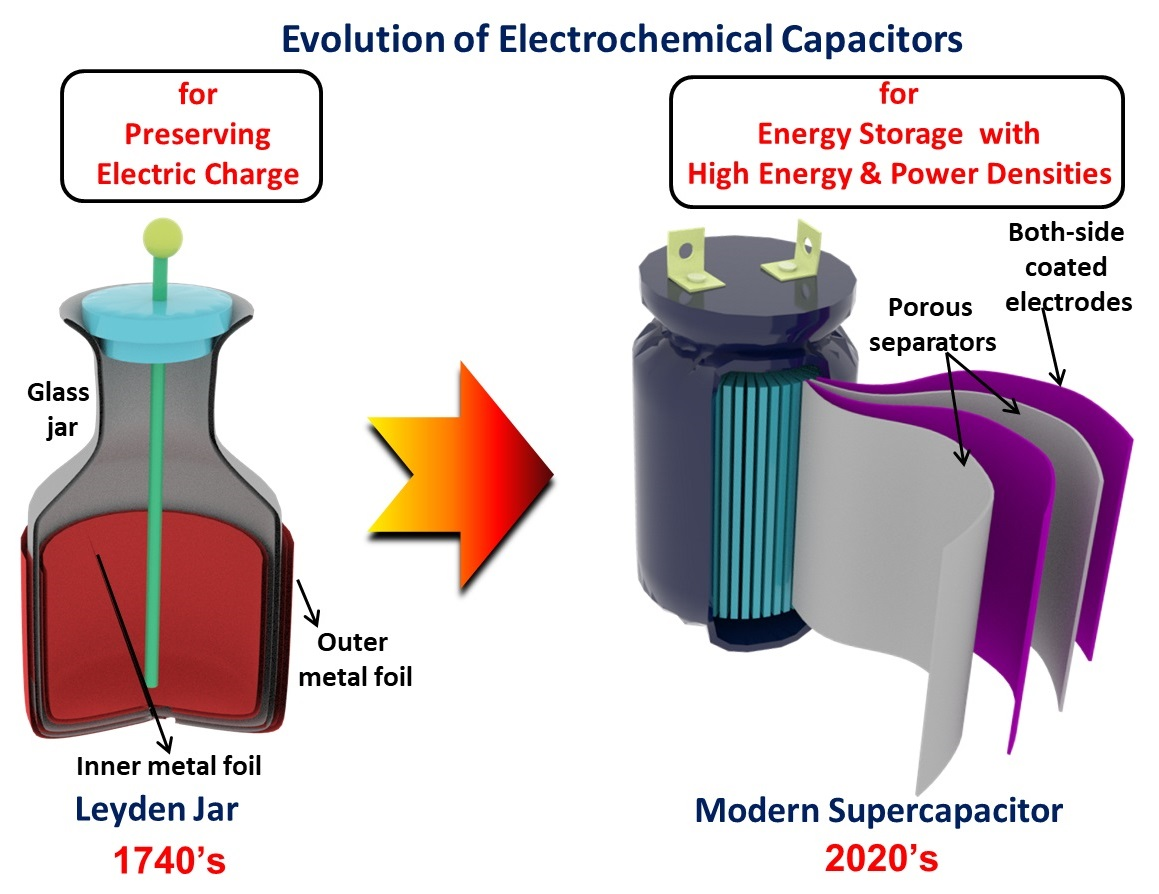
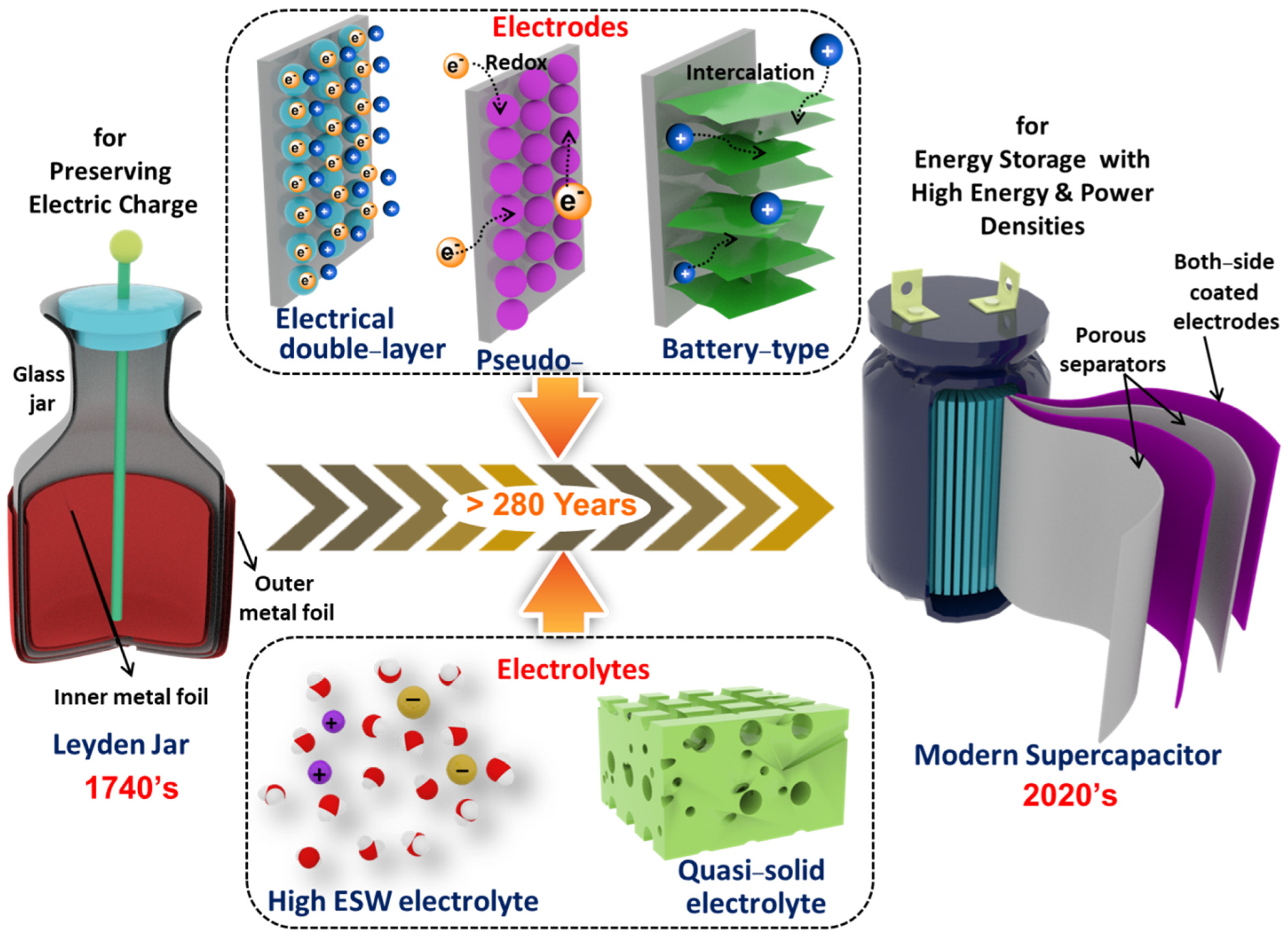
1. Introduction
2. Components of Supercapacitors
2.1. Electrode Materials
2.1.1. Carbon-Based Materials
2.1.2. Transition Metal-Based Compounds
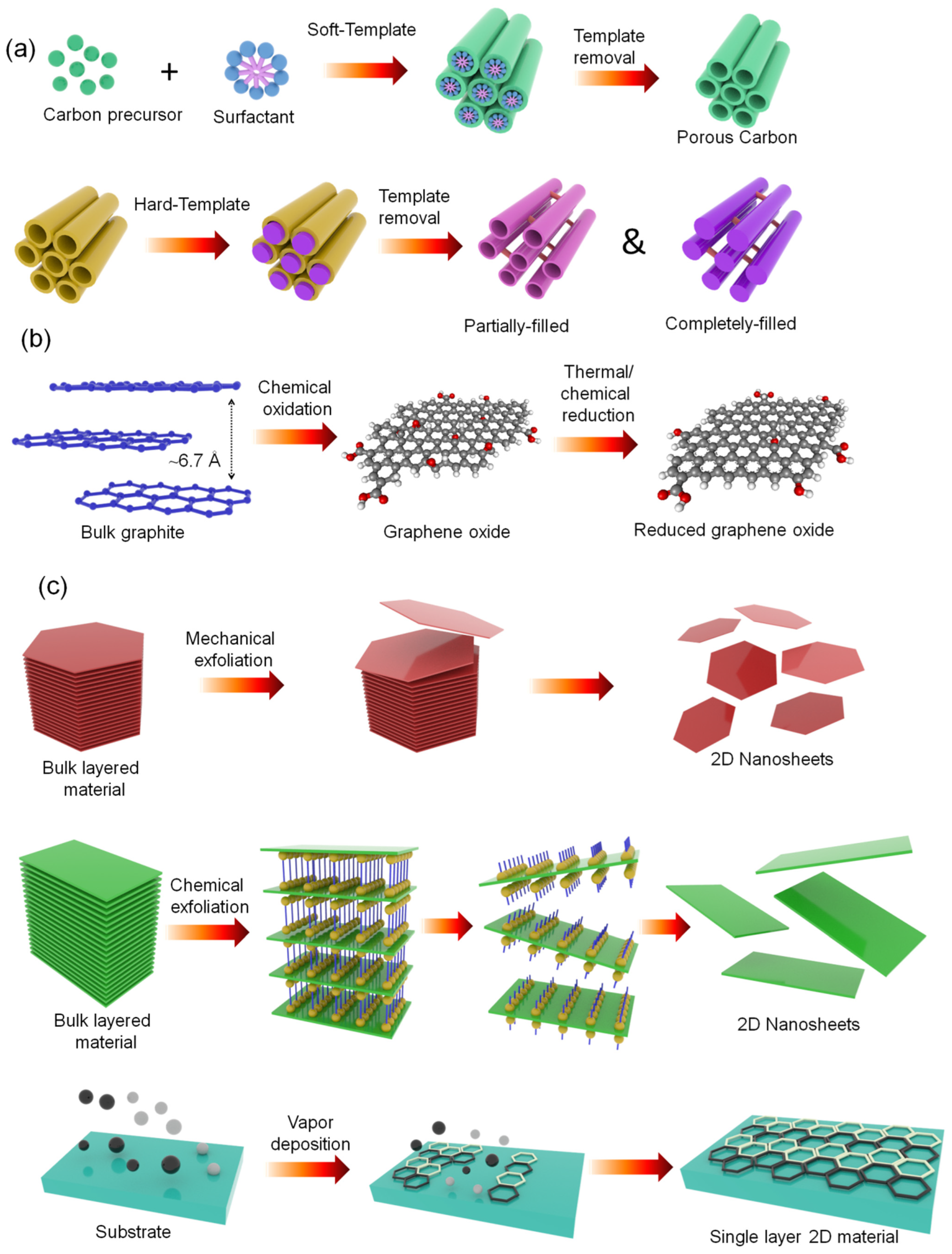
2.1.3. 2D Layered Materials
2.1.4. Redox-Active Polymers
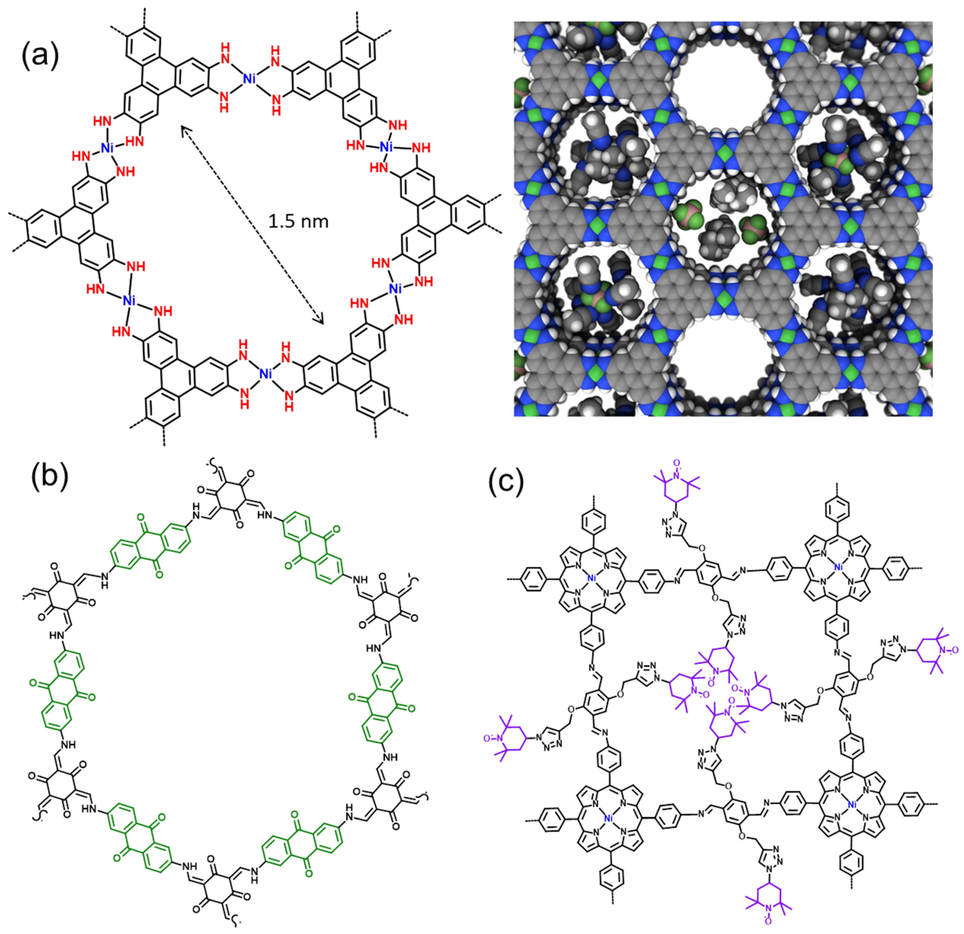
2.1.5. Metal-Organic and Covalent Organic Frameworks

2.2. Binder and Conductive Additives
2.3. Current Collectors
2.4. Electrolytes
2.4.1. Conventional Aqueous Electrolytes
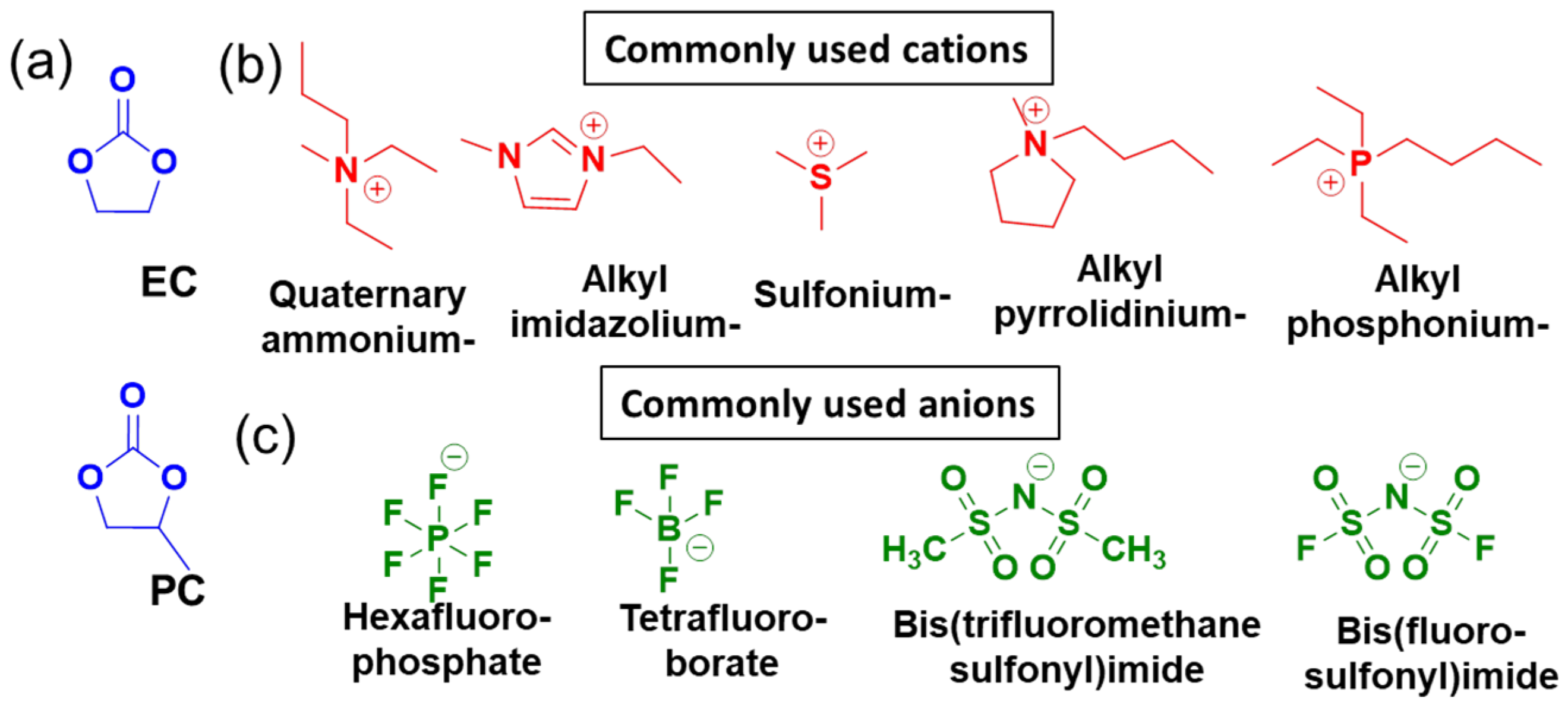
2.4.2. Conventional Nonaqueous Electrolytes
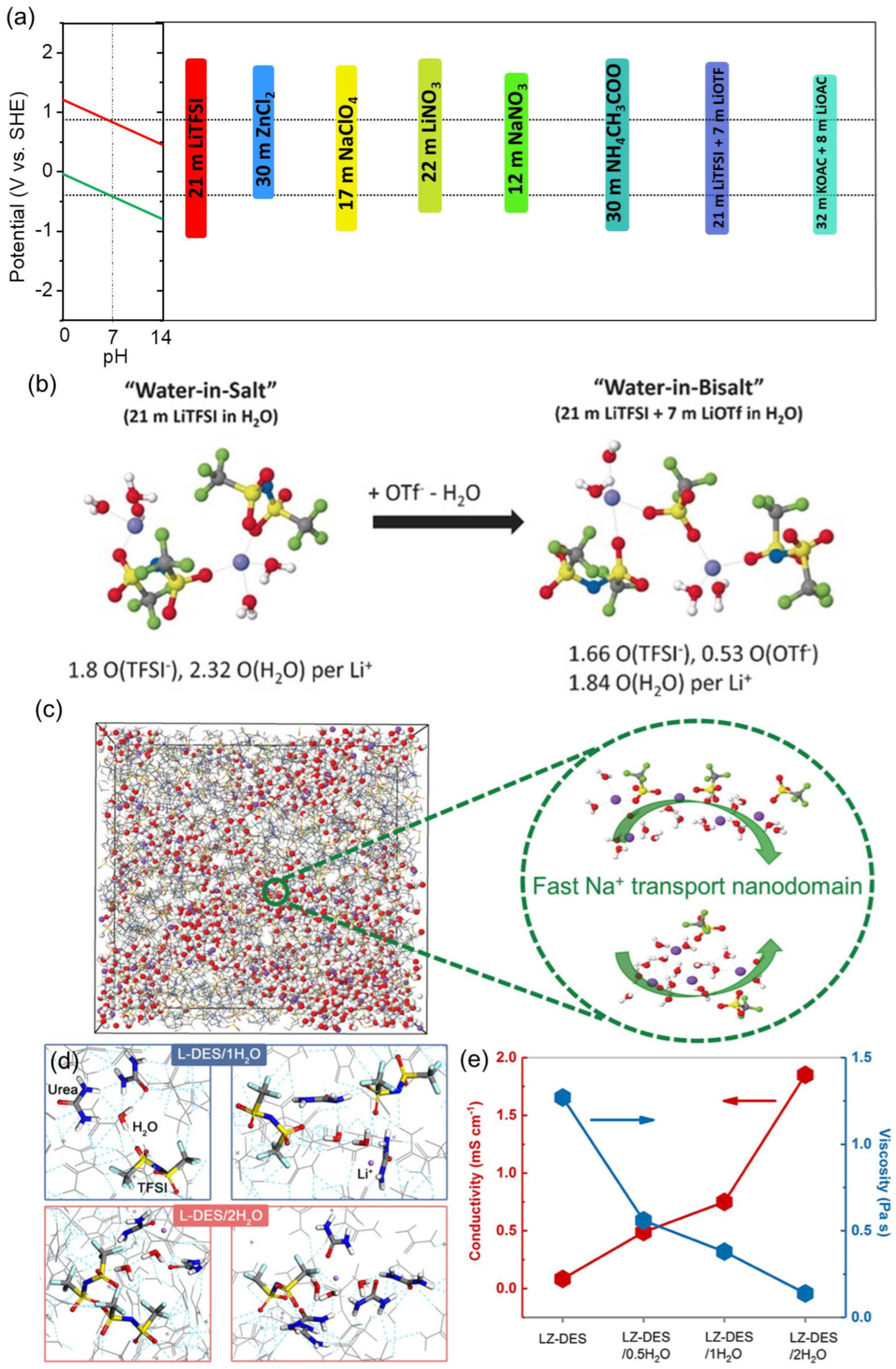
2.4.3. Unconventional Electrolytes

2.5. Separators
3. Electrochemical Characterization of Materials (Electrodes and Electrolyte Systems) and Assembly-Testing of Supercapacitors
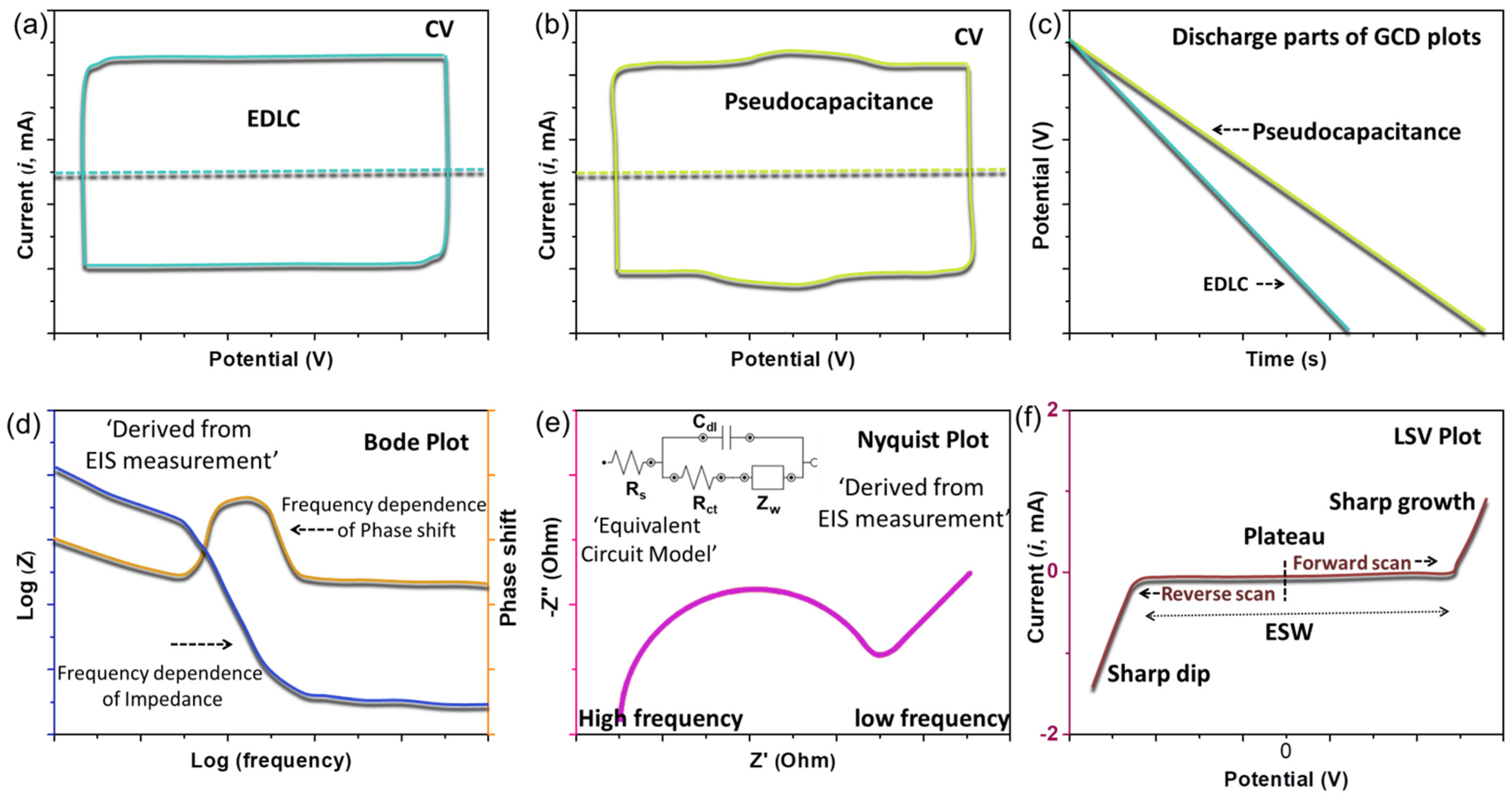
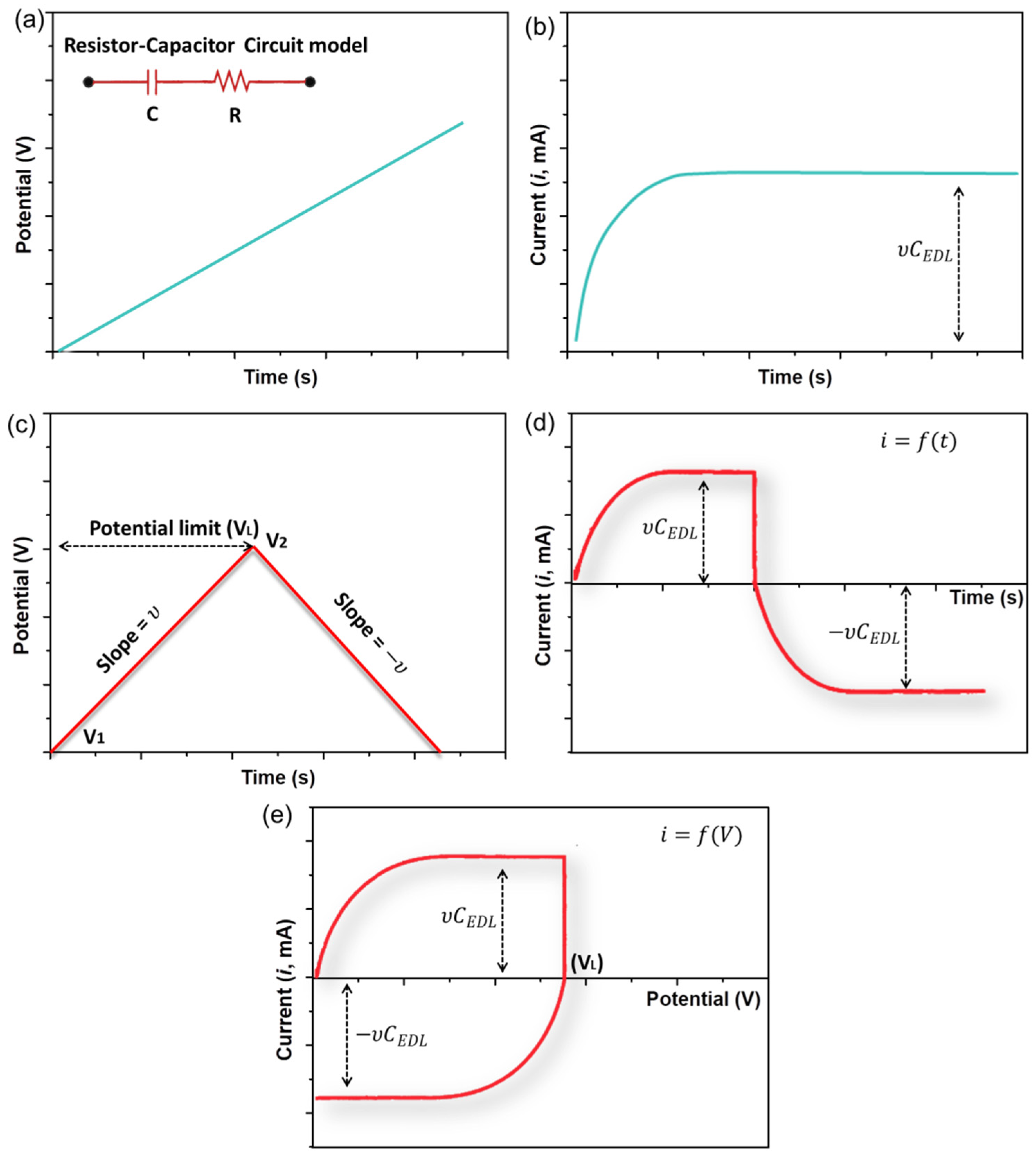
3.1. Cyclic Voltammetry
3.2. Galvanostatic Charge–Discharge (GCD)
3.3. Electrochemical Impedance Spectroscopy (EIS)
3.4. Linear-Sweep Voltammetry (LSV)
4. Charge Storage Mechanism and Electrochemical Kinetics of Electrode–Electrolyte Interfaces
4.1. Charge Storage Mechanism Based on the Electrical Double-Layer Formation
4.2. Charge Storage Mechanism Based on Pseudocapacitance
4.3. Charge Storage Mechanism Based on Battery-like Behavior

| S. No. | Electrode Material | Electrolyte | Specific Capacitance (F g−1) at Specific Current (mA g−1) | Cyclic Stability (no. Cycles) | Specific Energy (Wh kg−1)/ Specific Power (W kg−1)/ |
|---|---|---|---|---|---|
| EDL-capacitive materials | |||||
| 1. | N-doped mesoporous carbon [127] | 0.5 M H2SO4 | 428/250 | >98% (20,000) | 11/~250 |
| 2. | Activated Carbon (Chitin/Polystyrene) [128] | 1 M H2SO4 | 567/500 | >73% (10,000) | -- |
| 3. | Porous carbon/RGO [129] | 1 M H2SO4 | 775 (F cm−3)/500 | >93% (10,000) | ~10 W h L−1/61 W L−1 |
| 4. | Porous carbon [130] | EMIMBF4/TEP (ionic liquid) | 53/500 | >86% (10,000) | 43/12 |
| Pseudocapacitive materials | |||||
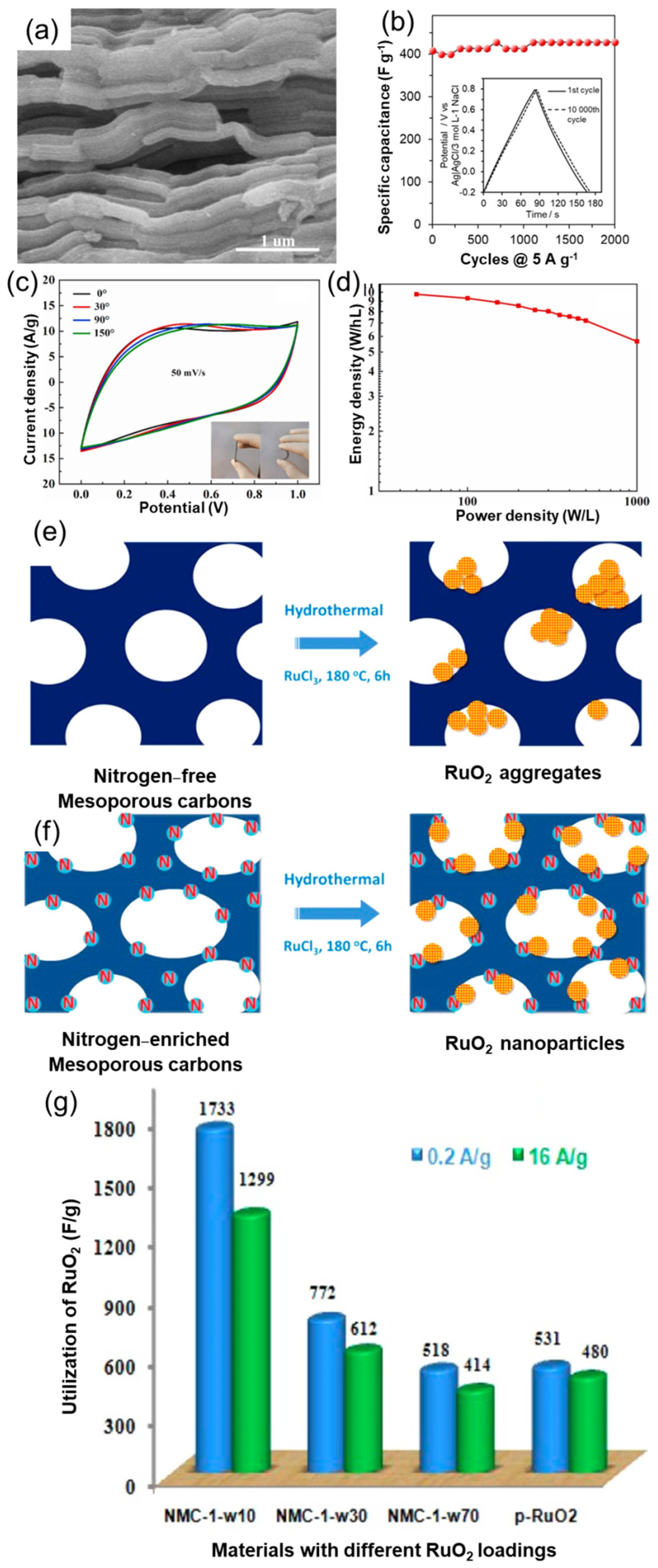
| 5. | RuO2/N-doped carbon [131] | 1 M H2SO4 | 1733/200 | >91% (2500) | -- |
| 6. | The Co3O4/3D carbon [138] | 3 M KOH | ~1315/1000 | >91% (12,000) | ~150/800 |
| 7. | Few layered MoS2 [140] | 0.5 M TEA BF4 | ~15/750 | >90% (5000) | >18/1125 |
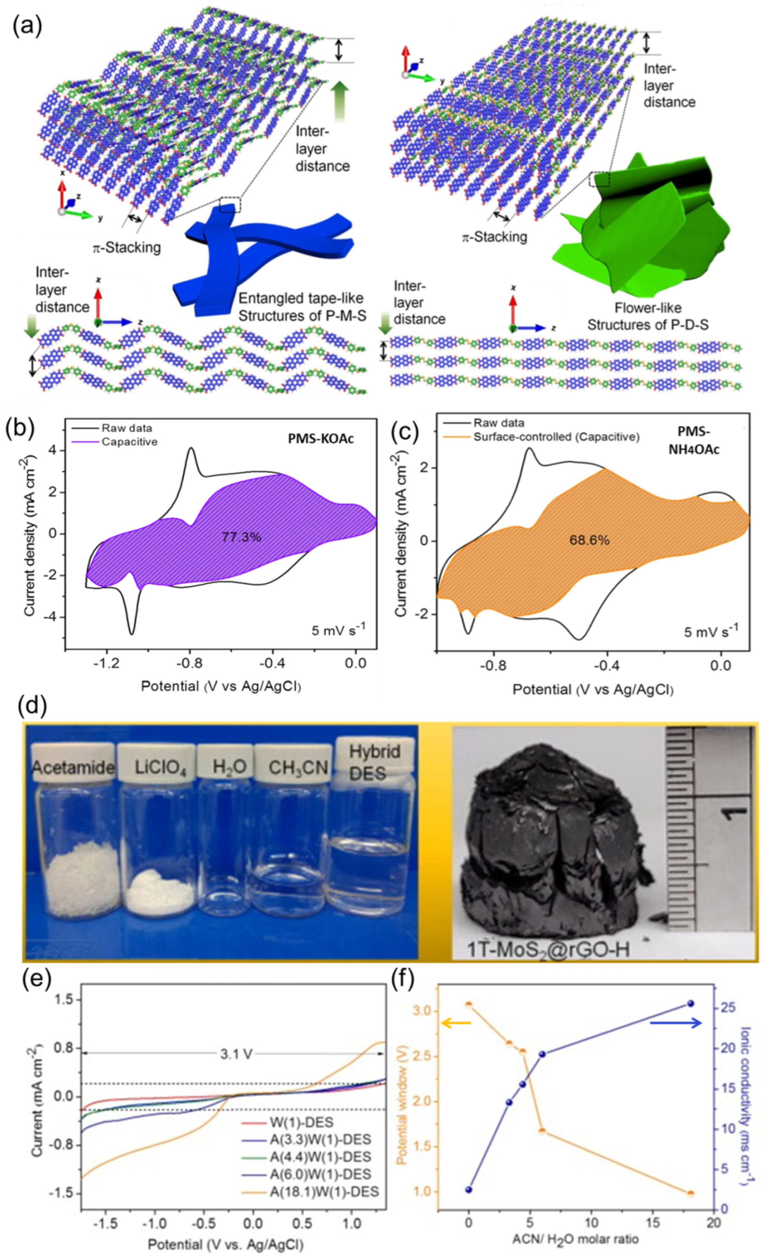
| 8. | Redox-active polymer (PMS) [141] | 27 m KOAc (WIS) | 75/1000 | >79% (10,000) | 22/8500 |
| 9. | MoS2-RGO [142] | Acetamide-LiClO4 (DES) | 42/1000 | >90% (20,000) | 31/1200 |
| Battery-type materials | |||||
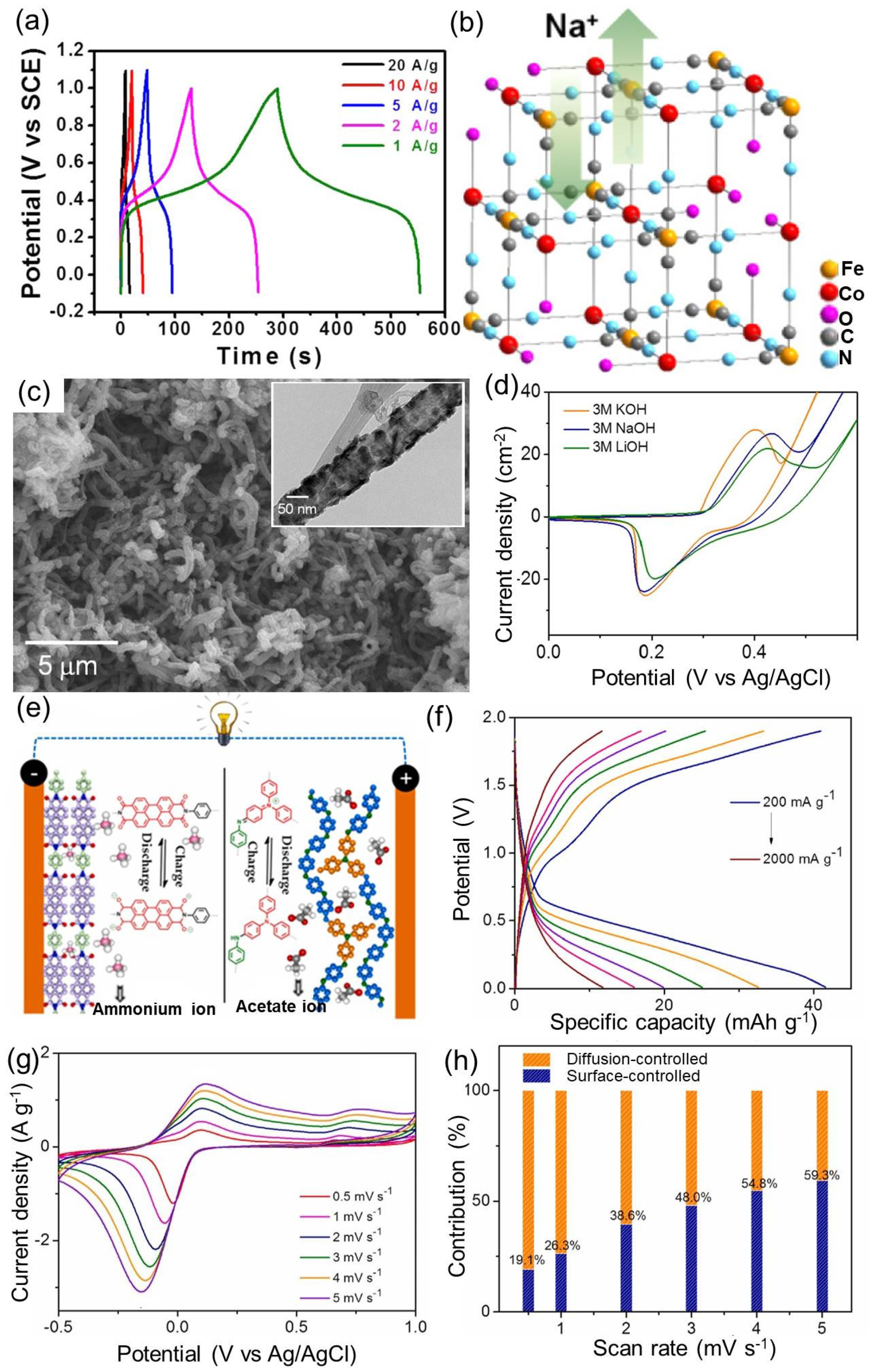
| 10. | Co-Fe-HCF [147] | 0.5 M Na2SO4 | 250/1000 * | 90% (5000) | 34/2500 |
| 11. | NiSe/CNT [151] | 3 M LiOH | 1007/1000 * | >75% * (500) | 32/823 |
| 12. | Mixed amine-containing copolymer [152] | 30 m NH4OAc | 42 mAh g−1/200 | 60% (2000) | >16/79 |
4.4. Investigation of Electrochemical Kinetics by Differentiating Pseudocapacitance and Battery-like Behaviors
5. Supercapacitors for Next-Generation Applications
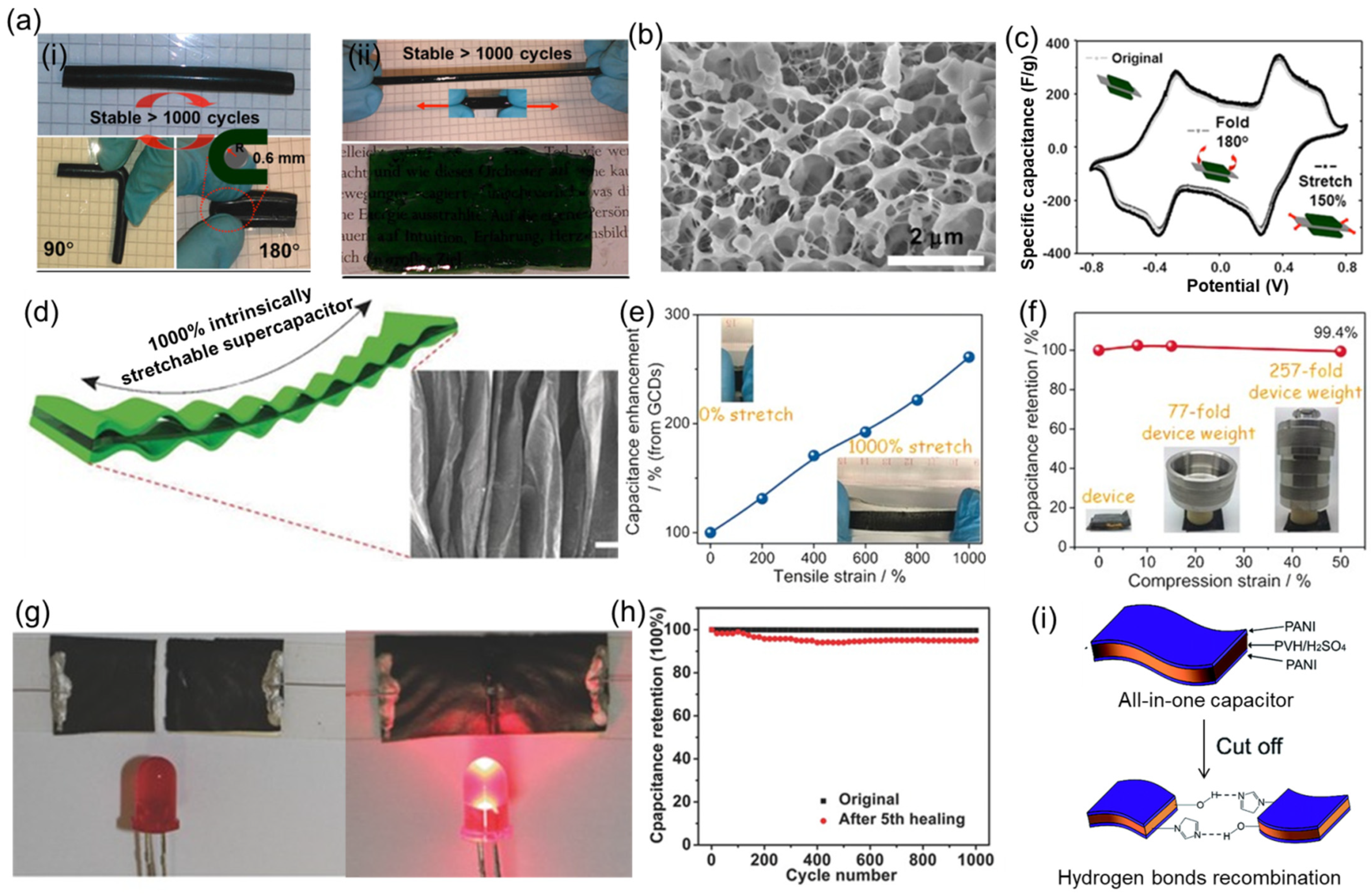
5.1. Stretchable/Wearable Supercapacitors
5.2. Self-Healing Supercapacitors
5.3. Self-Charging Supercapacitors
6. Summary and Outlook
Author Contributions
Funding
Data Availability Statement
Acknowledgments
Conflicts of Interest
References
- Liu, J.; Zhang, J.-G.; Yang, Z.; Lemmon, J.P.; Imhoff, C.; Graff, G.L.; Li, L.; Hu, J.; Wang, C.; Xiao, J.; et al. Materials Science and Materials Chemistry for Large Scale Electrochemical Energy Storage: From Transportation to Electrical Grid. Adv. Funct. Mater. 2013, 23, 929–946. [Google Scholar] [CrossRef]
- Yu, Z.; Tetard, L.; Zhai, L.; Thomas, J. Supercapacitor electrode materials: Nanostructures from 0 to 3 dimensions. Energy Environ. Sci. 2015, 8, 702–730. [Google Scholar] [CrossRef] [Green Version]
- Helmholtz, H. On some laws of the distribution of electric currents in physical conductors with application to animal electrical experiments. Ann. Phys. 1853, 165, 211–233. [Google Scholar] [CrossRef] [Green Version]
- Becker, H.E. Low Voltage Electrolytic Capacitor, General-Electric 2 800 616. 1957. Available online: https://patents.google.com/patent/US2800616A/en (accessed on 24 January 2023).
- Treacy, E.A. NEC Corporation. Encyclopedia Britannica. 2020. Available online: https://www.britannica.com/topic/NEC-Corporation (accessed on 25 January 2023).
- Bullard, G.L.; Sierra-Alcazar, H.B.; Lee, H.L.; Morris, J.L. Operating principles of the ultracapacitor. IEEE Trans. Magn. 1989, 25, 102–106. [Google Scholar] [CrossRef]
- Choi, C.; Ashby, D.S.; Butts, D.M.; DeBlock, R.H.; Wei, Q.; Lau, J.; Dunn, B. Achieving high energy density and high power density with pseudocapacitive materials. Nat. Rev. Mater. 2020, 5, 5–19. [Google Scholar] [CrossRef]
- Yu, F.; Huang, T.; Zhang, P.; Tao, Y.; Cui, F.-Z.; Xie, Q.; Yao, S.; Wang, F. Design and synthesis of electrode materials with both battery-type and capacitive charge storage. Energy Storage Mater. 2019, 22, 235–255. [Google Scholar] [CrossRef]
- Vlad, A.; Singh, N.; Rolland, J.; Melinte, S.; Ajayan, P.M.; Gohy, J.F. Hybrid supercapacitor-battery materials for fast electrochemical charge storage. Sci. Rep. 2014, 4, 4315. [Google Scholar] [CrossRef] [Green Version]
- Dubal, D.P.; Ayyad, O.; Ruiz, V.; Gómez-Romero, P. Hybrid energy storage: The merging of battery and supercapacitor chemistries. Chem. Soc. Rev. 2015, 44, 1777–1790. [Google Scholar] [CrossRef]
- Zhang, X.; Jiang, C.; Liang, J.; Wu, W. Electrode materials and device architecture strategies for flexible supercapacitors in wearable energy storage. J. Mater. Chem. A 2021, 9, 8099–8128. [Google Scholar] [CrossRef]
- Guo, X.; Zheng, S.; Zhang, G.; Xiao, X.; Li, X.; Xu, Y.; Xue, H.; Pang, H. Nanostructured graphene-based materials for flexible energy storage. Energy Storage Mater. 2017, 9, 150–169. [Google Scholar] [CrossRef]
- Liang, T.; Hou, R.; Dou, Q.; Zhang, H.; Yan, X. The Applications of Water-in-Salt Electrolytes in Electrochemical Energy Storage Devices. Adv. Funct. Mater. 2021, 31, 2006749. [Google Scholar] [CrossRef]
- Da Silva, L.M.; Cesar, R.; Moreira, C.M.R.; Santos, J.H.M.; De Souza, L.G.; Pires, B.M.; Vicentini, R.; Nunes, W.; Zanin, H. Reviewing the fundamentals of supercapacitors and the difficulties involving the analysis of the electrochemical findings obtained for porous electrode materials. Energy Storage Mater. 2020, 27, 555–590. [Google Scholar] [CrossRef]
- Lv, T.; Liu, M.; Zhu, D.; Gan, L.; Chen, T. Nanocarbon-Based Materials for Flexible All-Solid-State Supercapacitors. Adv. Mater. 2018, 30, 1705489. [Google Scholar] [CrossRef]
- Wang, Y.; Zhang, L.; Hou, H.; Xu, W.; Duan, G.; He, S.; Liu, K.; Jiang, S. Recent progress in carbon-based materials for supercapacitor electrodes: A review. J. Mater. Sci. 2021, 56, 173–200. [Google Scholar] [CrossRef]
- Duan, G.; Zhao, L.; Chen, L.; Wang, F.; He, S.; Jiang, S.; Zhang, Q. ZnCl2 regulated flax-based porous carbon fibers for supercapacitors with good cycling stability. New J. Chem. 2021, 45, 22602–22609. [Google Scholar] [CrossRef]
- Dai, L.; Chang, D.W.; Baek, J.-B.; Lu, W. Carbon Nanomaterials for Advanced Energy Conversion and Storage. Small 2012, 8, 1130–1166. [Google Scholar] [CrossRef] [PubMed]
- Xu, T.; Du, H.; Liu, H.; Liu, W.; Zhang, X.; Si, C.; Liu, P.; Zhang, K. Advanced Nanocellulose-Based Composites for Flexible Functional Energy Storage Devices. Adv. Mater. 2021, 33, 2101368. [Google Scholar] [CrossRef]
- Ariharan, A.; Ramesh, K.; Vinayagamoorthi, R.; Rani, M.S.; Viswanathan, B.; Ramaprabhu, S.; Nandhakumar, V. Biomass derived phosphorous containing porous carbon material for hydrogen storage and high-performance supercapacitor applications. J. Energy Storage 2021, 35, 102185. [Google Scholar] [CrossRef]
- Fu, F.; Yang, D.; Fan, Y.; Qiu, X.; Huang, J.; Li, Z.; Zhang, W. Nitrogen-rich accordion-like lignin porous carbon via confined self-assembly template and in-situ mild activation strategy for high-performance supercapacitors. J. Colloid Interface Sci. 2022, 628, 90–99. [Google Scholar] [CrossRef]
- Xiao, J.; Li, H.; Zhang, H.; He, S.; Zhang, Q.; Liu, K.; Jiang, S.; Duan, G.; Zhang, K. Nanocellulose and its derived composite electrodes toward supercapacitors: Fabrication, properties, and challenges. J. Bioresour. Bioprod. 2022, 7, 245–269. [Google Scholar] [CrossRef]
- Guo, W.; Guo, X.; Yang, L.; Wang, T.; Zhang, M.; Duan, G.; Liu, X.; Li, Y. Synthetic melanin facilitates MnO supercapacitors with high specific capacitance and wide operation potential window. Polymer 2021, 235, 124276. [Google Scholar] [CrossRef]
- Li, H.; Cao, L.; Zhang, H.; Tian, Z.; Zhang, Q.; Yang, F.; Yang, H.; He, S.; Jiang, S. Intertwined carbon networks derived from Polyimide/Cellulose composite as porous electrode for symmetrical supercapacitor. J. Colloid Interface Sci. 2022, 609, 179–187. [Google Scholar] [CrossRef]
- Wei, L.; Deng, W.; Li, S.; Wu, Z.; Cai, J.; Luo, J. Sandwich-like chitosan porous carbon Spheres/MXene composite with high specific capacitance and rate performance for supercapacitors. J. Bioresour. Bioprod. 2022, 7, 63–72. [Google Scholar] [CrossRef]
- Zheng, S.; Zhang, J.; Deng, H.; Du, Y.; Shi, X. Chitin derived nitrogen-doped porous carbons with ultrahigh specific surface area and tailored hierarchical porosity for high performance supercapacitors. J. Bioresour. Bioprod. 2021, 6, 142–151. [Google Scholar] [CrossRef]
- Huang, J.; Zhao, B.; Liu, T.; Mou, J.; Jiang, Z.; Liu, J.; Li, H.; Liu, M. Wood-Derived Materials for Advanced Electrochemical Energy Storage Devices. Adv. Funct. Mater. 2019, 29, 1902255. [Google Scholar] [CrossRef]
- Arjunan, A.; Kim, S.-K. Bioinspired Sustainable Sheetlike Porous Carbon Derived from Cassia fistula Flower Petal as an Electrode for High-Performance Supercapacitors. Energy Fuels 2022, 36, 9337–9346. [Google Scholar] [CrossRef]
- Yang, J.; Li, H.; He, S.; Du, H.; Liu, K.; Zhang, C.; Jiang, S. Facile Electrodeposition of NiCo2O4 Nanosheets on Porous Carbonized Wood for Wood-Derived Asymmetric Supercapacitors. Polymers 2022, 14, 2521. [Google Scholar] [CrossRef]
- Grądzka, E.; Wysocka-Żołopa, M.; Winkler, K. Fullerene-Based Conducting Polymers: N-Dopable Materials for Charge Storage Application. Adv. Energy Mater. 2020, 10, 2001443. [Google Scholar] [CrossRef]
- Xu, T.; Shen, W.; Huang, W.; Lu, X. Fullerene micro/nanostructures: Controlled synthesis and energy applications. Mater. Today Nano 2020, 11, 100081. [Google Scholar] [CrossRef]
- Chen, K.; Song, S.; Liu, F.; Xue, D. Structural design of graphene for use in electrochemical energy storage devices. Chem. Soc. Rev. 2015, 44, 6230–6257. [Google Scholar] [CrossRef]
- Wu, Y.; Ma, B.; Cheng, S.; Liu, Y.; Chen, S.; Fu, J.; Xie, E. Three-dimensional micro/nano-interconnected scaffold graphene-based micro-supercapacitors with high electrochemical performance. Electrochim. Acta 2022, 427, 140864. [Google Scholar] [CrossRef]
- Cao, L.; Li, H.; Liu, X.; Liu, S.; Zhang, L.; Xu, W.; Yang, H.; Hou, H.; He, S.; Zhao, Y.; et al. Nitrogen, sulfur co-doped hierarchical carbon encapsulated in graphene with “sphere-in-layer” interconnection for high-performance supercapacitor. J. Colloid Interface Sci. 2021, 599, 443–452. [Google Scholar] [CrossRef]
- Yu, M.; Qiu, W.; Wang, F.; Zhai, T.; Fang, P.; Lu, X.; Tong, Y. Three dimensional architectures: Design, assembly and application in electrochemical capacitors. J. Mater. Chem. A 2015, 3, 15792–15823. [Google Scholar] [CrossRef]
- Xu, Z.; Deng, W.; Wang, X. 3D Hierarchical Carbon-Rich Micro-/Nanomaterials for Energy Storage and Catalysis. Electrochem. Energy Rev. 2021, 4, 269–335. [Google Scholar] [CrossRef]
- Mahmood, N.; De Castro, I.A.; Pramoda, K.; Khoshmanesh, K.; Bhargava, S.K.; Kalantar-Zadeh, K. Atomically thin two-dimensional metal oxide nanosheets and their heterostructures for energy storage. Energy Storage Mater. 2019, 16, 455–480. [Google Scholar] [CrossRef]
- Dong, D. Ternary Composite MnO2@MoS2/Polypyrrole from In-situ Synthesis for Binder-free and Flexible Supercapacitor. J. Bioresour. Bioprod. 2019, 4, 242–250. [Google Scholar] [CrossRef]
- Li, Q.; Zheng, S.; Xu, Y.; Xue, H.; Pang, H. Ruthenium based materials as electrode materials for supercapacitors. Chem. Eng. J. 2018, 333, 505–518. [Google Scholar] [CrossRef]
- Wang, H.; Dai, H. Strongly coupled inorganic–nano-carbon hybrid materials for energy storage. Chem. Soc. Rev. 2013, 42, 3088–3113. [Google Scholar] [CrossRef]
- Orangi, J.; Beidaghi, M. A Review of the Effects of Electrode Fabrication and Assembly Processes on the Structure and Electrochemical Performance of 2D MXenes. Adv. Funct. Mater. 2020, 30, 2005305. [Google Scholar] [CrossRef]
- Lin, L.; Lei, W.; Zhang, S.; Liu, Y.; Wallace, G.G.; Chen, J. Two-dimensional transition metal dichalcogenides in supercapacitors and secondary batteries. Energy Storage Mater. 2019, 19, 408–423. [Google Scholar] [CrossRef]
- Zhai, S.; Wei, L.; Karahan, H.E.; Chen, X.; Wang, C.; Zhang, X.; Chen, J.; Wang, X.; Chen, Y. 2D materials for 1D electrochemical energy storage devices. Energy Storage Mater. 2019, 19, 102–123. [Google Scholar] [CrossRef]
- Hu, M.; Zhang, H.; Hu, T.; Fan, B.; Wang, X.; Li, Z. Emerging 2D MXenes for supercapacitors: Status, challenges and prospects. Chem. Soc. Rev. 2020, 49, 6666–6693. [Google Scholar] [CrossRef] [PubMed]
- Li, X.; Du, D.; Zhang, Y.; Xing, W.; Xue, Q.; Yan, Z. Layered double hydroxides toward high-performance supercapacitors. J. Mater. Chem. A 2017, 5, 15460–15485. [Google Scholar] [CrossRef]
- Ju, J.; Ma, J.; Wang, Y.; Cui, Y.; Han, P.; Cui, G. Solid-state energy storage devices based on two-dimensional nano-materials. Energy Storage Mater. 2019, 20, 269–290. [Google Scholar] [CrossRef]
- Tang, Q.; Jiang, D.-E. Stabilization and Band-Gap Tuning of the 1T-MoS2 Monolayer by Covalent Functionalization. Chem. Mat. 2015, 27, 3743–3748. [Google Scholar] [CrossRef] [Green Version]
- Zhang, Y.; Ang, E.H.; Yang, Y.; Ye, M.; Du, W.; Li, C.C. Interlayer Chemistry of Layered Electrode Materials in Energy Storage Devices. Adv. Funct. Mater. 2021, 31, 2007358. [Google Scholar] [CrossRef]
- Zhao, Z.; Xia, K.; Hou, Y.; Zhang, Q.; Ye, Z.; Lu, J. Designing flexible, smart and self-sustainable supercapacitors for portable/wearable electronics: From conductive polymers. Chem. Soc. Rev. 2021, 50, 12702–12743. [Google Scholar] [CrossRef]
- Schon, T.B.; McAllister, B.T.; Li, P.-F.; Seferos, D.S. The rise of organic electrode materials for energy storage. Chem. Soc. Rev. 2016, 45, 6345–6404. [Google Scholar] [CrossRef] [PubMed] [Green Version]
- Lima, R.M.A.P.; Alcaraz-Espinoza, J.J.; da Silva, F.A.G., Jr.; de Oliveira, H.P. Multifunctional Wearable Electronic Textiles Using Cotton Fibers with Polypyrrole and Carbon Nanotubes. ACS Appl. Mater. Interfaces 2018, 10, 13783–13795. [Google Scholar] [CrossRef]
- Han, X.; Xiao, G.; Wang, Y.; Chen, X.; Duan, G.; Wu, Y.; Gong, X.; Wang, H. Design and fabrication of conductive polymer hydrogels and their applications in flexible supercapacitors. J. Mater. Chem. A 2020, 8, 23059–23095. [Google Scholar] [CrossRef]
- Yang, H.; Lee, J.; Cheong, J.Y.; Wang, Y.; Duan, G.; Hou, H.; Jiang, S.; Kim, I.-D. Molecular engineering of carbonyl organic electrodes for rechargeable metal-ion batteries: Fundamentals, recent advances, and challenges. Energy Environ. Sci. 2021, 14, 4228–4267. [Google Scholar] [CrossRef]
- Okhay, O.; Tkach, A. Polyaniline—Graphene Electrodes Prepared by Electropolymerization for High-Performance Capacitive Electrodes: A Brief Review. Batteries 2022, 8, 191. [Google Scholar] [CrossRef]
- Liu, J.; Song, X.; Zhang, T.; Liu, S.; Wen, H.; Chen, L. 2D Conductive Metal–Organic Frameworks: An Emerging Platform for Electrochemical Energy Storage. Angew. Chem.—Int. Ed. 2021, 60, 5612–5624. [Google Scholar] [CrossRef] [PubMed]
- Liu, X.; Shi, C.; Zhai, C.; Cheng, M.; Liu, Q.; Wang, G. Cobalt-Based Layered Metal–Organic Framework as an Ultrahigh Capacity Supercapacitor Electrode Material. ACS Appl. Mater. Interfaces 2016, 8, 4585–4591. [Google Scholar] [CrossRef]
- Shao, D.; Wang, L.; Lu, B.; Guo, J.; Zhang, S.; Lu, Y. A high N content cobalt-based metal organic framework with nanorod structure for supercapacitor electrode material. J. Electroanal. Chem. 2019, 847, 113188. [Google Scholar] [CrossRef]
- Sheberla, D.; Bachman, J.C.; Elias, J.S.; Sun, C.-J.; Shao-Horn, Y.; Dincă, M. Conductive MOF electrodes for stable supercapacitors with high areal capacitance. Nat. Mater. 2017, 16, 220–224. [Google Scholar] [CrossRef]
- Sanati, S.; Abazari, R.; Albero, J.; Morsali, A.; García, H.; Liang, Z.; Zou, R. Metal–Organic Framework Derived Bimetallic Materials for Electrochemical Energy Storage. Angew. Chem.—Int. Ed. 2021, 60, 11048–11067. [Google Scholar] [CrossRef]
- Li, M.; Liu, J.; Zhang, T.; Song, X.; Chen, W.; Chen, L. 2D Redox-Active Covalent Organic Frameworks for Supercapacitors: Design, Synthesis, and Challenges. Small 2021, 17, 2005073. [Google Scholar] [CrossRef]
- Khattak, A.M.; Ghazi, Z.A.; Liang, B.; Khan, N.A.; Iqbal, A.; Li, L.; Tang, Z. A redox-active 2D covalent organic framework with pyridine moieties capable of faradaic energy storage. J. Mater. Chem. A 2016, 4, 16312–16317. [Google Scholar] [CrossRef]
- DeBlase, C.R.; Hernández-Burgos, K.; Silberstein, K.E.; Rodríguez-Calero, G.G.; Bisbey, R.P.; Abruña, H.D.; Dichtel, W.R. Rapid and Efficient Redox Processes within 2D Covalent Organic Framework Thin Films. ACS Nano 2015, 9, 3178–3183. [Google Scholar] [CrossRef]
- Xu, F.; Xu, H.; Chen, X.; Wu, D.; Wu, Y.; Liu, H.; Gu, C.; Fu, R.; Jiang, D. Radical Covalent Organic Frameworks: A General Strategy to Immobilize Open-Accessible Polyradicals for High-Performance Capacitive Energy Storage. Angew. Chem.—Int. Ed. 2015, 54, 6814–6818. [Google Scholar] [CrossRef] [PubMed]
- Chen, H.; Ling, M.; Hencz, L.; Ling, H.Y.; Li, G.; Lin, Z.; Liu, G.; Zhang, S. Exploring Chemical, Mechanical, and Electrical Functionalities of Binders for Advanced Energy-Storage Devices. Chem. Rev. 2018, 118, 8936–8982. [Google Scholar] [CrossRef] [PubMed]
- Zhong, S.; Zhan, C.; Cao, D. Zeolitic imidazolate framework-derived nitrogen-doped porous carbons as high performance supercapacitor electrode materials. Carbon 2015, 85, 51–59. [Google Scholar] [CrossRef]
- Bresser, D.; Buchholz, D.; Moretti, A.; Varzi, A.; Passerini, S. Alternative binders for sustainable electrochemical energy storage—The transition to aqueous electrode processing and bio-derived polymers. Energy Environ. Sci. 2018, 11, 3096–3127. [Google Scholar] [CrossRef] [Green Version]
- Zheng, Y.; Huang, X.; Chen, J.; Wu, K.; Wang, J.; Zhang, X. A Review of Conductive Carbon Materials for 3D Printing: Materials, Technologies, Properties, and Applications. Materials 2021, 14, 3911. [Google Scholar] [CrossRef]
- Liu, L.; Zhao, H.; Lei, Y. Review on Nanoarchitectured Current Collectors for Pseudocapacitors. Small Methods 2019, 3, 1800341. [Google Scholar] [CrossRef]
- Abdisattar, A.; Yeleuov, M.; Daulbayev, C.; Askaruly, K.; Tolynbekov, A.; Taurbekov, A.; Prikhodko, N. Recent advances and challenges of current collectors for supercapacitors. Electrochem. Commun. 2022, 142, 107373. [Google Scholar] [CrossRef]
- Brayek, M.; Jemni, M.A.; Driss, Z.; Kantchev, G.; Abid, M.S. Study of Spark-Ignition Engine Fueled with Hydrogen Produced by the Reaction Between Aluminum and Water in Presence of KOH. Arab. J. Sci. Eng. 2019, 44, 695–705. [Google Scholar] [CrossRef]
- Liu, X.; Jung, H.-G.; Kim, S.-O.; Choi, H.-S.; Lee, S.; Moon, J.H.; Lee, J.K. Silicon/copper dome-patterned electrodes for high-performance hybrid supercapacitors. Sci. Rep. 2013, 3, 3183. [Google Scholar] [CrossRef] [Green Version]
- Kuenzel, M.; Bresser, D.; Kim, G.-T.; Axmann, P.; Wohlfahrt-Mehrens, M.; Passerini, S. Unveiling and Amplifying the Benefits of Carbon-Coated Aluminum Current Collectors for Sustainable LiNi0.5Mn1.5O4 Cathodes. ACS Appl. Energy Mater. 2020, 3, 218–230. [Google Scholar] [CrossRef] [Green Version]
- Chiam, S.L.; Lim, H.N.; Hafiz, S.M.; Pandikumar, A.; Huang, N.M. Electrochemical Performance of Supercapacitor with Stacked Copper Foils Coated with Graphene Nanoplatelets. Sci. Rep. 2018, 8, 3093. [Google Scholar] [CrossRef] [PubMed] [Green Version]
- Wen, Y.H.; Shao, L.; Zhao, P.C.; Wang, B.Y.; Cao, G.P.; Yang, Y.S. Carbon coated stainless steel mesh as a low-cost and corrosion-resistant current collector for aqueous rechargeable batteries. J. Mater. Chem. A 2017, 5, 15752–15758. [Google Scholar] [CrossRef]
- Zhang, Y.-Z.; Wang, Y.; Cheng, T.; Lai, W.-Y.; Pang, H.; Huang, W. Flexible supercapacitors based on paper substrates: A new paradigm for low-cost energy storage. Chem. Soc. Rev. 2015, 44, 5181–5199. [Google Scholar] [CrossRef] [PubMed]
- Josef, E.; Yan, R.; Guterman, R.; Oschatz, M. Electrospun Carbon Fibers Replace Metals as a Current Collector in Supercapacitors. ACS Appl. Energy Mater. 2019, 2, 5724–5733. [Google Scholar] [CrossRef]
- Luo, P.; Huang, L. Carbon Paper as Current Collectors in Graphene Hydrogel Electrodes for High-Performance Supercapacitors. Nanomaterials 2020, 10, 746. [Google Scholar] [CrossRef] [Green Version]
- Liu, Z.; Bai, S.; Liu, B.; Guo, P.; Lv, M.; Liu, D.; He, D. Interfacial modification of a lightweight carbon foam current collector for high-energy density Si/LCO lithium-ion batteries. J. Mater. Chem. A 2017, 5, 13168–13175. [Google Scholar] [CrossRef]
- Cao, Z.; Zhang, J.; Ding, Y.; Li, Y.; Shi, M.; Yue, H.; Qiao, Y.; Yin, Y.; Yang, S. In situ synthesis of flexible elastic N-doped carbon foam as a carbon current collector and interlayer for high-performance lithium sulfur batteries. J. Mater. Chem. A 2016, 4, 8636–8644. [Google Scholar] [CrossRef]
- Li, M.; Wang, C.; Chen, Z.; Xu, K.; Lu, J. New Concepts in Electrolytes. Chem. Rev. 2020, 120, 6783–6819. [Google Scholar] [CrossRef]
- Xia, L.; Yu, L.; Hu, D.; Chen, G.Z. Electrolytes for electrochemical energy storage. Mat. Chem. Front. 2017, 1, 584–618. [Google Scholar] [CrossRef]
- Peng, J.; Zhang, W.; Wang, S.; Huang, Y.; Wang, J.-Z.; Liu, H.-K.; Dou, S.-X.; Chou, S.-L. The Emerging Electrochemical Activation Tactic for Aqueous Energy Storage: Fundamentals, Applications, and Future. Adv. Funct. Mater. 2022, 32, 2111720. [Google Scholar] [CrossRef]
- Zang, X.; Shen, C.; Sanghadasa, M.; Lin, L. High-Voltage Supercapacitors Based on Aqueous Electrolytes. ChemElectroChem 2019, 6, 976–988. [Google Scholar] [CrossRef]
- Iqbal, M.Z.; Zakar, S.; Haider, S.S. Role of aqueous electrolytes on the performance of electrochemical energy storage device. J. Electroanal. Chem. 2020, 858, 113793. [Google Scholar] [CrossRef]
- Nguyen, T.; Montemor, M.d.F. Metal Oxide and Hydroxide–Based Aqueous Supercapacitors: From Charge Storage Mechanisms and Functional Electrode Engineering to Need-Tailored Devices. Adv. Sci. 2019, 6, 1801797. [Google Scholar] [CrossRef]
- Sajjad, M.; Khan, M.I.; Cheng, F.; Lu, W. A review on selection criteria of aqueous electrolytes performance evaluation for advanced asymmetric supercapacitors. J. Energy Storage 2021, 40, 102729. [Google Scholar] [CrossRef]
- Krummacher, J.; Schütter, C.; Hess, L.H.; Balducci, A. Non-aqueous electrolytes for electrochemical capacitors. Curr. Opin. Electrochem. 2018, 9, 64–69. [Google Scholar] [CrossRef]
- Simon, P.; Gogotsi, Y. Capacitive Energy Storage in Nanostructured Carbon–Electrolyte Systems. Acc. Chem. Res. 2013, 46, 1094–1103. [Google Scholar] [CrossRef] [PubMed]
- Brandon, E.J.; Smart, M.C.; West, W.C. Low-temperature performance of electrochemical capacitors using acetonitrile/methyl formate electrolytes and activated carbon fabric electrodes. J. Mater. Res. 2020, 35, 113–121. [Google Scholar] [CrossRef]
- Barthel, J.; Gores, H.-J.; Schmeer, G.; Wachter, R. Non-aqueous electrolyte solutions in chemistry and modern technology. In Physical and Inorganic Chemistry; Springer: Berlin/Heidelberg, Germany, 1983; pp. 33–144. [Google Scholar]
- Lyklema, J. Principles of interactions in non-aqueous electrolyte solutions. Curr. Opin. Colloid Interface Sci. 2013, 18, 116–128. [Google Scholar] [CrossRef]
- Ye, W.; Wang, H.; Ning, J.; Zhong, Y.; Hu, Y. New types of hybrid electrolytes for supercapacitors. J. Energy Chem. 2021, 57, 219–232. [Google Scholar] [CrossRef]
- Venâncio, R.; Vicentini, R.; Costa, L.H.; Teófilo, R.; Da Silva, L.M.; Zanin, H. In-situ electrochemical and operando Raman techniques to investigate the effect of porosity in different carbon electrodes in organic electrolyte supercapacitors. J. Energy Storage 2022, 50, 104219. [Google Scholar] [CrossRef]
- Wang, X.; Salari, M.; Jiang, D.-E.; Chapman Varela, J.; Anasori, B.; Wesolowski, D.J.; Dai, S.; Grinstaff, M.W.; Gogotsi, Y. Electrode material–ionic liquid coupling for electrochemical energy storage. Nat. Rev. Mater. 2020, 5, 787–808. [Google Scholar] [CrossRef]
- Pan, S.; Yao, M.; Zhang, J.; Li, B.; Xing, C.; Song, X.; Su, P.; Zhang, H. Recognition of Ionic Liquids as High-Voltage Electrolytes for Supercapacitors. Front. Chem. 2020, 8, 261. [Google Scholar] [CrossRef] [PubMed]
- Yu, L.; Chen, G.Z. Ionic Liquid-Based Electrolytes for Supercapacitor and Supercapattery. Front. Chem. 2019, 7, 272. [Google Scholar] [CrossRef] [PubMed] [Green Version]
- Kim, E.; Han, J.; Ryu, S.; Choi, Y.; Yoo, J. Ionic Liquid Electrolytes for Electrochemical Energy Storage Devices. Materials 2021, 14, 4000. [Google Scholar] [CrossRef]
- Tian, X.; Zhu, Q.; Xu, B. “Water-in-Salt” Electrolytes for Supercapacitors: A Review. ChemSusChem 2021, 14, 2501–2515. [Google Scholar] [CrossRef] [PubMed]
- Lv, T.; Suo, L. Water-in-salt widens the electrochemical stability window: Thermodynamic and kinetic factors. Curr. Opin. Electrochem. 2021, 29, 100818. [Google Scholar] [CrossRef]
- Santos, J.P.A.; Pinzón, M.J.; Santos, É.A.; Vicentini, R.; Pagan, C.J.B.; Da Silva, L.M.; Zanin, H. Boosting energy-storage capability in carbon-based supercapacitors using low-temperature water-in-salt electrolytes. J. Energy Chem. 2022, 70, 521–530. [Google Scholar] [CrossRef]
- Suo, L.; Borodin, O.; Sun, W.; Fan, X.; Yang, C.; Wang, F.; Gao, T.; Ma, Z.; Schroeder, M.; von Cresce, A.; et al. Advanced High-Voltage Aqueous Lithium-Ion Battery Enabled by “Water-in-Bisalt” Electrolyte. Angew. Chem.—Int. Ed. 2016, 55, 7136–7141. [Google Scholar] [CrossRef] [PubMed]
- Jiang, L.; Liu, L.; Yue, J.; Zhang, Q.; Zhou, A.; Borodin, O.; Suo, L.; Li, H.; Chen, L.; Xu, K.; et al. High-Voltage Aqueous Na-Ion Battery Enabled by Inert-Cation-Assisted Water-in-Salt Electrolyte. Adv. Mater. 2020, 32, 1904427. [Google Scholar] [CrossRef]
- Wu, J.; Liang, Q.; Yu, X.; Lü, Q.-F.; Ma, L.; Qin, X.; Chen, G.; Li, B. Deep Eutectic Solvents for Boosting Electrochemical Energy Storage and Conversion: A Review and Perspective. Adv. Funct. Mater. 2021, 31, 2011102. [Google Scholar] [CrossRef]
- Ge, X.; Gu, C.; Wang, X.; Tu, J. Deep eutectic solvents (DESs)-derived advanced functional materials for energy and environmental applications: Challenges, opportunities, and future vision. J. Mater. Chem. A 2017, 5, 8209–8229. [Google Scholar] [CrossRef]
- Boisset, A.; Menne, S.; Jacquemin, J.; Balducci, A.; Anouti, M. Deep eutectic solvents based on N-methylacetamide and a lithium salt as suitable electrolytes for lithium-ion batteries. Phys. Chem. Chem. Phys. 2013, 15, 20054–20063. [Google Scholar] [CrossRef] [PubMed] [Green Version]
- Zhao, J.; Zhang, J.; Yang, W.; Chen, B.; Zhao, Z.; Qiu, H.; Dong, S.; Zhou, X.; Cui, G.; Chen, L. “Water-in-deep eutectic solvent” electrolytes enable zinc metal anodes for rechargeable aqueous batteries. Nano Energy 2019, 57, 625–634. [Google Scholar] [CrossRef]
- Yuan, B.; Wen, K.; Chen, D.; Liu, Y.; Dong, Y.; Feng, C.; Han, Y.; Han, J.; Zhang, Y.; Xia, C.; et al. Composite Separators for Robust High Rate Lithium Ion Batteries. Adv. Funct. Mater. 2021, 31, 2101420. [Google Scholar] [CrossRef]
- Li, J.; Jia, H.; Ma, S.; Xie, L.; Wei, X.-X.; Dai, L.; Wang, H.; Su, F.; Chen, C.-M. Separator Design for High-Performance Supercapacitors: Requirements, Challenges, Strategies, and Prospects. ACS Energy Lett. 2023, 8, 56–78. [Google Scholar] [CrossRef]
- Wang, X.; Chen, Y.; Schmidt, O.G.; Yan, C. Engineered nanomembranes for smart energy storage devices. Chem. Soc. Rev. 2016, 45, 1308–1330. [Google Scholar] [CrossRef]
- Zhang, W.; Liu, H.; Zhang, X.; Li, X.; Zhang, G.; Cao, P. 3D Printed Micro-Electrochemical Energy Storage Devices: From Design to Integration. Adv. Funct. Mater. 2021, 31, 2104909. [Google Scholar] [CrossRef]
- Bon, C.Y.; Mohammed, L.; Kim, S.; Manasi, M.; Isheunesu, P.; Lee, K.S.; Ko, J.M. Flexible poly(vinyl alcohol)-ceramic composite separators for supercapacitor applications. J. Ind. Eng. Chem. 2018, 68, 173–179. [Google Scholar] [CrossRef]
- Liu, M.; Turcheniuk, K.; Fu, W.; Yang, Y.; Liu, M.; Yushin, G. Scalable, safe, high-rate supercapacitor separators based on the Al2O3 nanowire Polyvinyl butyral nonwoven membranes. Nano Energy 2020, 71, 104627. [Google Scholar] [CrossRef]
- Torvinen, K.; Lehtimäki, S.; Keränen, J.T.; Sievänen, J.; Vartiainen, J.; Hellén, E.; Lupo, D.; Tuukkanen, S. Pigment-cellulose nanofibril composite and its application as a separator-substrate in printed supercapacitors. Electron. Mater. Lett. 2015, 11, 1040–1047. [Google Scholar] [CrossRef]
- Yang, D.; Qi, L.; Ma, J. Eggshell Membrane Templating of Hierarchically Ordered Macroporous Networks Composed of TiO2 Tubes. Adv. Mater. 2002, 14, 1543–1546. [Google Scholar] [CrossRef]
- Cai, J.; Liu, S.; Feng, J.; Kimura, S.; Wada, M.; Kuga, S.; Zhang, L. Cellulose–Silica Nanocomposite Aerogels by In Situ Formation of Silica in Cellulose Gel. Angew. Chem.—Int. Ed. 2012, 51, 2076–2079. [Google Scholar] [CrossRef] [PubMed]
- Tammela, P.; Olsson, H.; Strømme, M.; Nyholm, L. The influence of electrode and separator thickness on the cell resistance of symmetric cellulose–polypyrrole-based electric energy storage devices. J. Power Sources 2014, 272, 468–475. [Google Scholar] [CrossRef]
- Egorov, V.; Gulzar, U.; Zhang, Y.; Breen, S.; O’Dwyer, C. Evolution of 3D Printing Methods and Materials for Electrochemical Energy Storage. Adv. Mater. 2020, 32, 2000556. [Google Scholar] [CrossRef] [PubMed]
- Baig, M.M.; Gul, I.H.; Baig, S.M.; Shahzad, F. The complementary advanced characterization and electrochemical techniques for electrode materials for supercapacitors. J. Energy Storage 2021, 44, 103370. [Google Scholar] [CrossRef]
- Elgrishi, N.; Rountree, K.J.; McCarthy, B.D.; Rountree, E.S.; Eisenhart, T.T.; Dempsey, J.L. A Practical Beginner’s Guide to Cyclic Voltammetry. J. Chem. Educ. 2018, 95, 197–206. [Google Scholar] [CrossRef]
- Zeng, L.; Wu, T.; Ye, T.; Mo, T.; Qiao, R.; Feng, G. Modeling galvanostatic charge–discharge of nanoporous supercapacitors. Nat. Comp. Sci. 2021, 1, 725–731. [Google Scholar] [CrossRef]
- Kurzweil, P.; Shamonin, M. State-of-Charge Monitoring by Impedance Spectroscopy during Long-Term Self-Discharge of Supercapacitors and Lithium-Ion Batteries. Batteries 2018, 4, 35. [Google Scholar] [CrossRef] [Green Version]
- Zhang, S.; Pan, N. Supercapacitors Performance Evaluation. Adv. Energy Mater. 2015, 5, 1401401. [Google Scholar] [CrossRef] [Green Version]
- Bhide, A.; Hofmann, J.; Katharina Dürr, A.; Janek, J.; Adelhelm, P. Electrochemical stability of non-aqueous electrolytes for sodium-ion batteries and their compatibility with Na0.7CoO2. Phys. Chem. Chem. Phys. 2014, 16, 1987–1998. [Google Scholar] [CrossRef] [PubMed]
- Forse, A.C.; Merlet, C.; Griffin, J.M.; Grey, C.P. New Perspectives on the Charging Mechanisms of Supercapacitors. J. Am. Chem. Soc. 2016, 138, 5731–5744. [Google Scholar] [CrossRef] [PubMed] [Green Version]
- Simon, P.; Gogotsi, Y. Charge storage mechanism in nanoporous carbons and its consequence for electrical double layer capacitors. Philos. Trans. R. Soc. A-Math. Phys. Eng. Sci. 2010, 368, 3457–3467. [Google Scholar] [CrossRef] [PubMed] [Green Version]
- Shao, H.; Wu, Y.-C.; Lin, Z.; Taberna, P.-L.; Simon, P. Nanoporous carbon for electrochemical capacitive energy storage. Chem. Soc. Rev. 2020, 49, 3005–3039. [Google Scholar] [CrossRef] [PubMed] [Green Version]
- Wang, L.; Sun, J.; Zhang, H.; Xu, L.; Liu, G. Preparation of benzoxazine-based N-doped mesoporous carbon material and its electrochemical behaviour as supercapacitor. J. Electroanal. Chem. 2020, 868, 114196. [Google Scholar] [CrossRef]
- Ferry, M.A.; Maruyama, J.; Asoh, T.-A.; Uyama, H. Porosity-Induced Improvement in KOH Activation of Chitin Nanofiber-Based Porous Carbon Leading to Ultrahigh Specific Capacitance. ChemSusChem 2022, 15, e202200932. [Google Scholar] [CrossRef]
- Wu, Q.; Gao, M.; Jiang, C.; Gu, X.; Wang, Z.; Huang, L.; Yu, S. Carbon-carbon dense network composite with hierarchical structure for additive-free and high volumetric performance supercapacitor. J. Power Sources 2021, 497, 229878. [Google Scholar] [CrossRef]
- Li, S.; Tian, Q.; Chen, J.; Chen, Y.; Guo, P.; Wei, C.; Cui, P.; Jiang, J.; Li, X.; Xu, Q. An intrinsically non-flammable organic electrolyte for wide temperature range supercapacitors. Chem. Eng. J. 2023, 457, 141265. [Google Scholar] [CrossRef]
- Zhang, C.; Xie, Y.; Zhao, M.; Pentecost, A.E.; Ling, Z.; Wang, J.; Long, D.; Ling, L.; Qiao, W. Enhanced Electrochemical Performance of Hydrous RuO2/Mesoporous Carbon Nanocomposites via Nitrogen Doping. ACS Appl. Mater. Interfaces 2014, 6, 9751–9759. [Google Scholar] [CrossRef]
- Chen, G.Z. Linear and non-linear pseudocapacitances with or without diffusion control. Prog. Nat. Sci.-Mater. Int. 2021, 31, 792–800. [Google Scholar] [CrossRef]
- Chen, G.Z. Supercapattery: Merit merge of capacitive and Nernstian charge storage mechanisms. Curr. Opin. Electrochem. 2020, 21, 358–367. [Google Scholar] [CrossRef]
- Augustyn, V.; Simon, P.; Dunn, B. Pseudocapacitive oxide materials for high-rate electrochemical energy storage. Energy Environ. Sci. 2014, 7, 1597–1614. [Google Scholar] [CrossRef] [Green Version]
- Chen, R.; Yu, M.; Sahu, R.P.; Puri, I.K.; Zhitomirsky, I. The Development of Pseudocapacitor Electrodes and Devices with High Active Mass Loading. Adv. Energy Mater. 2020, 10, 1903848. [Google Scholar] [CrossRef]
- Fleischmann, S.; Mitchell, J.B.; Wang, R.; Zhan, C.; Jiang, D.-e.; Presser, V.; Augustyn, V. Pseudocapacitance: From Fundamental Understanding to High Power Energy Storage Materials. Chem. Rev. 2020, 120, 6738–6782. [Google Scholar] [CrossRef] [PubMed]
- Eftekhari, A.; Mohamedi, M. Tailoring pseudocapacitive materials from a mechanistic perspective. Mater. Today Energy 2017, 6, 211–229. [Google Scholar] [CrossRef]
- He, L.; Lin, C.; Zhao, Y.; Gao, W.; Zhang, H.; Lin, B.; Sun, D. A new strategy for porous carbon synthesis: Starch hydrogel as a carbon source for Co3O4@C supercapacitor electrodes. Ceram. Int. 2022, 48, 8104–8111. [Google Scholar] [CrossRef]
- Hanlon, D.; Backes, C.; Higgins, T.M.; Hughes, M.; O’Neill, A.; King, P.; McEvoy, N.; Duesberg, G.S.; Mendoza Sanchez, B.; Pettersson, H.; et al. Production of Molybdenum Trioxide Nanosheets by Liquid Exfoliation and Their Application in High-Performance Supercapacitors. Chem. Mat. 2014, 26, 1751–1763. [Google Scholar] [CrossRef]
- Pazhamalai, P.; Krishnamoorthy, K.; Manoharan, S.; Kim, S.J. High energy symmetric supercapacitor based on mechanically delaminated few-layered MoS2 sheets in organic electrolyte. J. Alloys Compd. 2019, 771, 803–809. [Google Scholar] [CrossRef]
- Seetha Lakshmi, K.C.; Ji, X.; Shao, L.-D.; Vedhanarayanan, B.; Lin, T.-W. Tailor-made organic polymers towards high voltage aqueous ammonium/potassium-ion asymmetric supercapacitors. Appl. Surf. Sci. 2022, 577, 151918. [Google Scholar] [CrossRef]
- Lien, C.-W.; Vedhanarayanan, B.; Chen, J.-H.; Lin, J.-Y.; Tsai, H.-H.; Shao, L.-D.; Lin, T.-W. Optimization of acetonitrile/water content in hybrid deep eutectic solvent for graphene/MoS2 hydrogel-based supercapacitors. Chem. Eng. J. 2021, 405, 126706. [Google Scholar] [CrossRef]
- Tsai, H.-H.; Lin, T.-J.; Vedhanarayanan, B.; Tsai, C.-C.; Chen, T.-Y.; Ji, X.; Lin, T.-W. A 1.9-V all-organic battery-supercapacitor hybrid device with high rate capability and wide temperature tolerance in a metal-free water-in-saltelectrolyte. J. Colloid Interface Sci. 2022, 612, 76–87. [Google Scholar] [CrossRef]
- Liu, H.; Liu, X.; Wang, S.; Liu, H.-K.; Li, L. Transition metal based battery-type electrodes in hybrid supercapacitors: A review. Energy Storage Mater. 2020, 28, 122–145. [Google Scholar] [CrossRef]
- Shaikh, N.S.; Kanjanaboos, P.; Lokhande, V.C.; Praserthdam, S.; Lokhande, C.D.; Shaikh, J.S. Engineering of Battery Type Electrodes for High Performance Lithium Ion Hybrid Supercapacitors. ChemElectroChem 2021, 8, 4686–4724. [Google Scholar] [CrossRef]
- Levi, M.D.; Lukatskaya, M.R.; Sigalov, S.; Beidaghi, M.; Shpigel, N.; Daikhin, L.; Aurbach, D.; Barsoum, M.W.; Gogotsi, Y. Solving the Capacitive Paradox of 2D MXene using Electrochemical Quartz-Crystal Admittance and In Situ Electronic Conductance Measurements. Adv. Energy Mater. 2015, 5, 1400815. [Google Scholar] [CrossRef]
- Zhao, F.; Wang, Y.; Xu, X.; Liu, Y.; Song, R.; Lu, G.; Li, Y. Cobalt Hexacyanoferrate Nanoparticles as a High-Rate and Ultra-Stable Supercapacitor Electrode Material. ACS Appl. Mater. Interfaces 2014, 6, 11007–11012. [Google Scholar] [CrossRef]
- Ji, J.; Zhang, L.L.; Ji, H.; Li, Y.; Zhao, X.; Bai, X.; Fan, X.; Zhang, F.; Ruoff, R.S. Nanoporous Ni(OH)2 Thin Film on 3D Ultrathin-Graphite Foam for Asymmetric Supercapacitor. ACS Nano 2013, 7, 6237–6243. [Google Scholar] [CrossRef] [PubMed]
- Dai, C.-S.; Chien, P.-Y.; Lin, J.-Y.; Chou, S.-W.; Wu, W.-K.; Li, P.-H.; Wu, K.-Y.; Lin, T.-W. Hierarchically Structured Ni3S2/Carbon Nanotube Composites as High Performance Cathode Materials for Asymmetric Supercapacitors. ACS Appl. Mater. Interfaces 2013, 5, 12168–12174. [Google Scholar] [CrossRef]
- Wang, X.; Li, M.; Chang, Z.; Wang, Y.; Chen, B.; Zhang, L.; Wu, Y. Orientated Co3O4 Nanocrystals on MWCNTs as Superior Battery-Type Positive Electrode Material for a Hybrid Capacitor. J. Electrochem. Soc. 2015, 162, A1966. [Google Scholar] [CrossRef]
- Chen, T.-Y.; Vedhanarayanan, B.; Lin, S.-Y.; Shao, L.-D.; Sofer, Z.; Lin, J.-Y.; Lin, T.-W. Electrodeposited NiSe on a forest of carbon nanotubes as a free-standing electrode for hybrid supercapacitors and overall water splitting. J. Colloid Interface Sci. 2020, 574, 300–311. [Google Scholar] [CrossRef]
- Lakshmi, K.C.S.; Ji, X.; Chen, T.-Y.; Vedhanarayanan, B.; Lin, T.-W. Pseudocapacitive and battery-type organic polymer electrodes for a 1.9 V hybrid supercapacitor with a record concentration of ammonium acetate. J. Power Sources 2021, 511, 230434. [Google Scholar] [CrossRef]
- Xie, J.; Yang, P.; Wang, Y.; Qi, T.; Lei, Y.; Li, C.M. Puzzles and confusions in supercapacitor and battery: Theory and solutions. J. Power Sources 2018, 401, 213–223. [Google Scholar] [CrossRef]
- Zhang, P.; Wang, F.; Yu, M.; Zhuang, X.; Feng, X. Two-dimensional materials for miniaturized energy storage devices: From individual devices to smart integrated systems. Chem. Soc. Rev. 2018, 47, 7426–7451. [Google Scholar] [CrossRef] [PubMed] [Green Version]
- Sumboja, A.; Liu, J.; Zheng, W.G.; Zong, Y.; Zhang, H.; Liu, Z. Electrochemical energy storage devices for wearable technology: A rationale for materials selection and cell design. Chem. Soc. Rev. 2018, 47, 5919–5945. [Google Scholar] [CrossRef]
- Wang, L.; Fu, X.; He, J.; Shi, X.; Chen, T.; Chen, P.; Wang, B.; Peng, H. Application Challenges in Fiber and Textile Electronics. Adv. Mater. 2020, 32, 1901971. [Google Scholar] [CrossRef]
- Chae, J.S.; Park, S.K.; Roh, K.C.; Park, H.S. Electrode materials for biomedical patchable and implantable energy storage devices. Energy Storage Mater. 2020, 24, 113–128. [Google Scholar] [CrossRef]
- Meng, F.; Li, Q.; Zheng, L. Flexible fiber-shaped supercapacitors: Design, fabrication, and multi-functionalities. Energy Storage Mater. 2017, 8, 85–109. [Google Scholar] [CrossRef]
- Cavallo, A.; Russo, A.; Canciello, G. Control of Supercapacitors for smooth EMA Operations in Aeronautical Applications. In Proceedings of the 2019 American Control Conference (ACC), Philadelphia, PA, USA, 10–12 July 2019; pp. 4948–4954. [Google Scholar]
- Sumsurooah, S.; He, Y.; Torchio, M.; Kouramas, K.; Guida, B.; Cuomo, F.; Atkin, J.; Bozhko, S.; Renzetti, A.; Russo, A.; et al. ENIGMA—A Centralised Supervisory Controller for Enhanced Onboard Electrical Energy Management with Model in the Loop Demonstration. Energies 2021, 14, 5518. [Google Scholar] [CrossRef]
- Wang, X.; Lu, X.; Liu, B.; Chen, D.; Tong, Y.; Shen, G. Flexible Energy-Storage Devices: Design Consideration and Recent Progress. Adv. Mater. 2014, 26, 4763–4782. [Google Scholar] [CrossRef] [PubMed]
- Mackanic, D.G.; Chang, T.-H.; Huang, Z.; Cui, Y.; Bao, Z. Stretchable electrochemical energy storage devices. Chem. Soc. Rev. 2020, 49, 4466–4495. [Google Scholar] [CrossRef] [PubMed]
- Wang, K.; Meng, Q.; Zhang, Y.; Wei, Z.; Miao, M. High-Performance Two-Ply Yarn Supercapacitors Based on Carbon Nanotubes and Polyaniline Nanowire Arrays. Adv. Mater. 2013, 25, 1494–1498. [Google Scholar] [CrossRef]
- Lee, H.; Yoo, J.-K.; Park, J.-H.; Kim, J.H.; Kang, K.; Jung, Y.S. A Stretchable Polymer–Carbon Nanotube Composite Electrode for Flexible Lithium-Ion Batteries: Porosity Engineering by Controlled Phase Separation. Adv. Energy Mater. 2012, 2, 976–982. [Google Scholar] [CrossRef]
- Hao, G.-P.; Hippauf, F.; Oschatz, M.; Wisser, F.M.; Leifert, A.; Nickel, W.; Mohamed-Noriega, N.; Zheng, Z.; Kaskel, S. Stretchable and Semitransparent Conductive Hybrid Hydrogels for Flexible Supercapacitors. ACS Nano 2014, 8, 7138–7146. [Google Scholar] [CrossRef] [PubMed]
- Li, H.; Lv, T.; Sun, H.; Qian, G.; Li, N.; Yao, Y.; Chen, T. Ultrastretchable and superior healable supercapacitors based on a double cross-linked hydrogel electrolyte. Nat. Commun. 2019, 10, 536. [Google Scholar] [CrossRef] [Green Version]
- Huang, Y.; Zhong, M.; Shi, F.; Liu, X.; Tang, Z.; Wang, Y.; Huang, Y.; Hou, H.; Xie, X.; Zhi, C. An Intrinsically Stretchable and Compressible Supercapacitor Containing a Polyacrylamide Hydrogel Electrolyte. Angew. Chem.-Int. Ed. 2017, 56, 9141–9145. [Google Scholar] [CrossRef]
- Chen, X.; Villa, N.S.; Zhuang, Y.; Chen, L.; Wang, T.; Li, Z.; Kong, T. Stretchable Supercapacitors as Emergent Energy Storage Units for Health Monitoring Bioelectronics. Adv. Energy Mater. 2020, 10, 1902769. [Google Scholar] [CrossRef]
- Gong, J.P. Materials both Tough and Soft. Science 2014, 344, 161–162. [Google Scholar] [CrossRef] [PubMed]
- Song, C.; Yun, J.; Keum, K.; Jeong, Y.R.; Park, H.; Lee, H.; Lee, G.; Oh, S.Y.; Ha, J.S. High performance wire-type supercapacitor with Ppy/CNT-ionic liquid/AuNP/carbon fiber electrode and ionic liquid based electrolyte. Carbon 2019, 144, 639–648. [Google Scholar] [CrossRef]
- Keum, K.; Lee, G.; Lee, H.; Yun, J.; Park, H.; Hong, S.Y.; Song, C.; Kim, J.W.; Ha, J.S. Wire-Shaped Supercapacitors with Organic Electrolytes Fabricated via Layer-by-Layer Assembly. ACS Appl. Mater. Interfaces 2018, 10, 26248–26257. [Google Scholar] [CrossRef]
- Guo, Y.; Li, W.; Yu, H.; Perepichka, D.F.; Meng, H. Flexible Asymmetric Supercapacitors via Spray Coating of a New Electrochromic Donor–Acceptor Polymer. Adv. Energy Mater. 2017, 7, 1601623. [Google Scholar] [CrossRef]
- Liu, Y.-Z.; Yao, W.; Gan, H.-M.; Sun, C.-Y.; Su, Z.-M.; Wang, X.-L. Polyoxometalates-Based Metal–Organic Frameworks Made by Electrodeposition and Carbonization Methods as Cathodes and Anodes for Asymmetric Supercapacitors. Chem.—Eur. J. 2019, 25, 16617–16624. [Google Scholar] [CrossRef]
- Lv, Z.; Luo, Y.; Tang, Y.; Wei, J.; Zhu, Z.; Zhou, X.; Li, W.; Zeng, Y.; Zhang, W.; Zhang, Y.; et al. Editable Supercapacitors with Customizable Stretchability Based on Mechanically Strengthened Ultralong MnO2 Nanowire Composite. Adv. Mater. 2018, 30, 1704531. [Google Scholar] [CrossRef]
- Jiao, S.; Zhou, A.; Wu, M.; Hu, H. Kirigami Patterning of MXene/Bacterial Cellulose Composite Paper for All-Solid-State Stretchable Micro-Supercapacitor Arrays. Adv. Sci. 2019, 6, 1900529. [Google Scholar] [CrossRef] [Green Version]
- Wang, H.; Zhu, B.; Jiang, W.; Yang, Y.; Leow, W.R.; Wang, H.; Chen, X. A Mechanically and Electrically Self-Healing Supercapacitor. Adv. Mater. 2014, 26, 3638–3643. [Google Scholar] [CrossRef] [PubMed]
- Liu, F.; Wang, J.; Pan, Q. An all-in-one self-healable capacitor with superior performance. J. Mater. Chem. A 2018, 6, 2500–2506. [Google Scholar] [CrossRef]
- Mai, W.; Yu, Q.; Han, C.; Kang, F.; Li, B. Self-Healing Materials for Energy-Storage Devices. Adv. Funct. Mater. 2020, 30, 1909912. [Google Scholar] [CrossRef]
- Son, D.; Kang, J.; Vardoulis, O.; Kim, Y.; Matsuhisa, N.; Oh, J.Y.; To, J.W.F.; Mun, J.; Katsumata, T.; Liu, Y.; et al. An integrated self-healable electronic skin system fabricated via dynamic reconstruction of a nanostructured conducting network. Nat. Nanotechnol. 2018, 13, 1057–1065. [Google Scholar] [CrossRef] [PubMed]
- Cao, Y.; Tan, Y.J.; Li, S.; Lee, W.W.; Guo, H.; Cai, Y.; Wang, C.; Tee, B.C.K. Self-healing electronic skins for aquatic environments. Nat. Electron. 2019, 2, 75–82. [Google Scholar] [CrossRef]
- White, S.R.; Sottos, N.R.; Geubelle, P.H.; Moore, J.S.; Kessler, M.R.; Sriram, S.R.; Brown, E.N.; Viswanathan, S. Autonomic healing of polymer composites. Nature 2001, 409, 794–797. [Google Scholar] [CrossRef] [PubMed]
- Park, S.; Thangavel, G.; Parida, K.; Li, S.; Lee, P.S. A Stretchable and Self-Healing Energy Storage Device Based on Mechanically and Electrically Restorative Liquid-Metal Particles and Carboxylated Polyurethane Composites. Adv. Mater. 2019, 31, 1805536. [Google Scholar] [CrossRef] [Green Version]
- Liu, R.; Wang, Z.L.; Fukuda, K.; Someya, T. Flexible self-charging power sources. Nat. Rev. Mater. 2022, 7, 870–886. [Google Scholar] [CrossRef]
- Luo, J.; Wang, Z.L. Recent advances in triboelectric nanogenerator based self-charging power systems. Energy Storage Mater. 2019, 23, 617–628. [Google Scholar] [CrossRef]
- Mi, Y.; Lu, Y.; Wang, X.; Zhao, Z.; Cao, X.; Wang, N. From Triboelectric Nanogenerator to Uninterrupted Power Supply System: The Key Role of Electrochemical Batteries and Supercapacitors. Batteries 2022, 8, 215. [Google Scholar] [CrossRef]
- Song, R.; Jin, H.; Li, X.; Fei, L.; Zhao, Y.; Huang, H.; Lai-Wa Chan, H.; Wang, Y.; Chai, Y. A rectification-free piezo-supercapacitor with a polyvinylidene fluoride separator and functionalized carbon cloth electrodes. J. Mater. Chem. A 2015, 3, 14963–14970. [Google Scholar] [CrossRef]
- Pazhamalai, P.; Krishnamoorthy, K.; Mariappan, V.K.; Sahoo, S.; Manoharan, S.; Kim, S.-J. A High Efficacy Self-Charging MoSe2 Solid-State Supercapacitor Using Electrospun Nanofibrous Piezoelectric Separator with Ionogel Electrolyte. Adv. Mater. Interfaces 2018, 5, 1800055. [Google Scholar] [CrossRef]
- Zhao, D.; Wang, H.; Khan, Z.U.; Chen, J.C.; Gabrielsson, R.; Jonsson, M.P.; Berggren, M.; Crispin, X. Ionic thermoelectric supercapacitors. Energy Environ. Sci. 2016, 9, 1450–1457. [Google Scholar] [CrossRef] [Green Version]


Disclaimer/Publisher’s Note: The statements, opinions and data contained in all publications are solely those of the individual author(s) and contributor(s) and not of MDPI and/or the editor(s). MDPI and/or the editor(s) disclaim responsibility for any injury to people or property resulting from any ideas, methods, instructions or products referred to in the content. |
© 2023 by the authors. Licensee MDPI, Basel, Switzerland. This article is an open access article distributed under the terms and conditions of the Creative Commons Attribution (CC BY) license (https://creativecommons.org/licenses/by/4.0/).
Share and Cite
Lakshmi, K.C.S.; Vedhanarayanan, B. High-Performance Supercapacitors: A Comprehensive Review on Paradigm Shift of Conventional Energy Storage Devices. Batteries 2023, 9, 202. https://doi.org/10.3390/batteries9040202
Lakshmi KCS, Vedhanarayanan B. High-Performance Supercapacitors: A Comprehensive Review on Paradigm Shift of Conventional Energy Storage Devices. Batteries. 2023; 9(4):202. https://doi.org/10.3390/batteries9040202
Chicago/Turabian StyleLakshmi, K. C. Seetha, and Balaraman Vedhanarayanan. 2023. "High-Performance Supercapacitors: A Comprehensive Review on Paradigm Shift of Conventional Energy Storage Devices" Batteries 9, no. 4: 202. https://doi.org/10.3390/batteries9040202