Article

Effect of Initial Structure on Performance of High-Entropy Oxide Anodes for Li-Ion Batteries

by
Otavio J. B. J. Marques
1,†,
Michael D. Walter
2,
Elena V. Timofeeva
3,4 and
Carlo U. Segre
1,2,*,†
1
Department of Mechanical, Materials and Aerospace Engineering, Illinois Institute of Technology, Chicago, IL 60616, USA
2
Department of Physics and CSRRI, Illinois Institute of Technology, Chicago, IL 60616, USA
3
Department of Chemistry, Illinois Institute of Technology, Chicago, IL 60616, USA
4
Influit Energy, LLC, Chicago, IL 60612, USA
*
Author to whom correspondence should be addressed.
These authors contributed equally to this work.
Batteries 2023, 9(2), 115; https://doi.org/10.3390/batteries9020115
Submission received: 4 January 2023 / Revised: 23 January 2023 / Accepted: 1 February 2023 / Published: 7 February 2023
(This article belongs to the Special Issue Electrode Materials for Rechargeable Lithium Batteries)

Abstract

:
Two different high-entropy oxide materials were synthesized and studied as Li-ion battery anodes. The two materials have the same active metal constituents but different inactive elements which result in different initial crystalline structures: rock salt for (MgFeCoNiZn)O and spinel for (TiFeCoNiZn) 3 O 4 . Local structural studies of the metal elements in these two materials over extended electrochemical cycling reveal that the redox processes responsible for the electrode capacity are independent of the initial crystallographic structure and that the capacity is solely dependent on the initial random distribution of the metal atoms and the amount of active metals in the starting material.

1. Introduction

Due to the increasing demand on portable electronics, electric vehicles, and green grid solutions, energy storage technologies have received much attention lately. In this scenario, lithium-ion batteries (LIBs) show great advantages compared to other chemistries, namely higher power and energy density, cycle life, and reversibility. The low theoretical capacity of current commercialized negative electrodes for LIBs (i.e., graphite ∼372 mAh/g) and sluggish Li-ion diffusivity, limits its utilization for high-energy applications [1,2,3,4,5]. Therefore, the development of new anode materials is crucial for the ever-increasing demand on energy storage technologies, and conversion-type high-entropy oxides (HEOs) have emerged as an alternative for next-generation electrodes [6].
HEOs constitute a new class of materials wherein, during high temperature annealing, the configurational entropy stabilizes a solid solution of five or more transition metals, overcoming the formation enthalpy of competing individual oxide phases, driving the Gibbs free energy to its lowest levels and favoring the formation of a single solid solution. The ability to mix non-soluble components in one entropy-stabilized phase expands the compositional space of elemental mixtures creating new opportunities for advanced energy materials discovery and design [5,7,8,9,10].
Previous studies on HEOs as anode in LIBs have focused primarily on materials with a wide variety of elemental combinations forming both the rock salt structure [6,11,12,13] and the spinel structure [14,15,16,17,18,19,20]. These materials show improved capacities, long cycling stability and high ionic conductivities, overcoming some expected drawbacks of conversion-type metal oxide electrodes, such as particle pulverization and fast capacity fading [21]. The key to advanced performance seems to be multiple elements having different roles in the electrochemical reaction, displaying a synergetic storage behavior, and attenuating the volume changes in the electrode. Some of the transition metals (i.e., Zn and Co) present in conversion-type HEO electrodes act as electrochemically active species contributing to the storage capacity, with complete reduction to their metallic state during the lithiation reaction. Others (i.e., Mg, Cu) provide structural stability, contributing to the long cycle life. Adding electrochemically inactive elements to HEO composition (i.e., MgO), is also an effective method to prevent pulverization and agglomeration of active domains.
A still unanswered question is whether the initial structure, rock salt or spinel, provides advantages to a Li-ion HEO electrode in terms of capacity, rate performance and cycle lifetime. In order to probe these effects, in this study, we have prepared two new HEO compounds, (MgFeCoNiZn)O and (TiFeCoNiZn) 3 O 4 and investigated their local structure and conversion mechanism using X-ray Absorption Spectroscopy (XAS).

2. Materials and Methods

Two HEO compositions (MgFeCoNiZn)O and (TiFeCoNiZn) 3 O 4 , were prepared from equimolar amounts of the monoxide precursors according to their respective compositions. The purity of the precursors were: MgO (Alfa Aesar, Haverhill, MA, USA, 99.95%), TiO (Sigma Aldrich, St. Louis, MO, USA, 99.9%), Fe 2 O 3 (Nanoamor, Houston, TX, USA, >99%) CoO (Thermo Fisher, Waltham, MA, USA, 99.995%), NiO (Alfa Aesar, 99.998%), and ZnO (Alfa Aesar, 99.999%). Both samples were prepared using a similar route. First, equimolar metal amounts of the oxides were mixed by ball milling (SPEX 8000, Metuchen, NJ, USA) for 1 h using a 4:1 ratio of 1/4″ diameter stainless steel balls to sample. The resulting material was pelletized in 0.5 g batches, sintered for 2 h with an initial heating rate of 10 °C/min, and quenched to room temperature in air. The (MgFeCoNiZn)O sample was sintered at 1300 °C while the (TiFeCoNiZn) 3 O 4 sample at 1600 °C. The difference in temperature is related to the presence of a secondary phase in the (TiFeCoNiZn) 3 O 4 sample, which was eliminated only at 1600 °C. Both high-entropy products were again ball milled for 30 min using a 10:1 ratio of balls to sample and sieved using a 500-mesh sieve (<25 µm) to result in a nanostructured powder. The crystal structures of the sintered and nanostructured samples were analyzed by powder X-ray diffraction (XRD; Bruker AXS, Madison, WI, USA, D2 Phaser, Cu K α radiation) from 10 to 80 degrees 2 θ . The resulting powder patterns were fitted by Pawley refinement using GSAS-II [22]. The particle morphology and elemental composition were analyzed by scanning electron microscopy (SEM; JEOL JSM-IT500HR, Akishima, JP) equipped with an energy dispersive X-ray spectrometer (EDS; Oxford Instruments Ultim-Max, Abingdon, UK).
The nanostructured (MgFeCoNiZn)O and (TiFeCoNiZn) 3 O 4 were tested as anodes in Li-ion batteries using a half-cell configuration. Electrodes were prepared by mixing active materials, carbon black and polyvinylidene fluoride (PVDF) in 70:20:10 wt.% proportions dispersed in N-Methyl-2-pyrrolidone (NMP). The resulting slurry was casted on Cu foil using a doctor blade, dried at 30 °C for 24 h at ambient conditions and cold rolled. CR2032 coin cells were assembled in an Ar-filled glovebox using metallic Li as a counter electrode. Celgard 2325 (25 µm) and LiPF 6 (3:7 EC:EMC 1M LIPASTE) were used as separator and electrolyte, respectively. The specific capacity and cycling stability of both compounds were tested by room temperature (∼25 °C) galvanostatic cycling of the cells using a BTS400 battery cycler (Neware, Shenzhen, China), at varying current densities (50 mA/g, 100 mA/g, 200 mA/g, 500 mA/g). Cyclic voltammetry was performed using an EZstat-Pro potentiostat (Nuvant Systems, Crown Point, IN, USA) at a series of sweep rates (0.2 mV/sC, 0.5 mV/sC, 0.8 mV/sC, 1 mV/sC, 1.2 mV/sC, 1.5 mV/s, 1.8 mV/sC, 2 mV/sC, 2.5 mV/sC, and 3 mV/sC).
Ex situ XAS measurements were taken on both electrode materials at different charging and cycle states: uncycled, 1st lithiated and delithiated states, and 100th lithiated and delithiated. The electrodes were extracted from the cells in an argon-filled glovebox, cleaned with DMC (dimethyl carbonate), and protected by Kapton tape. In order to prevent oxidation during transport and measurement, the lithiated electrodes were additionally vacuum sealed in polyethylene and removed from the glovebox shortly before measurement. Ti, Fe, Co, Ni, and Zn K-edges were measured in fluorescence mode at the Sector 10, 10-BM beamline of the Materials Research Collaborative Access Team (MRCAT) at the Advanced Photon Source, Argonne National Laboratory [23]. The resulting X-ray Near Edge Structure (XANES) and Extended X-ray Absorption Fine Structure (EXAFS) data were analyzed using the IFEFFIT-based Athena and Artemis software packages [24,25].

3. Results and Discussion

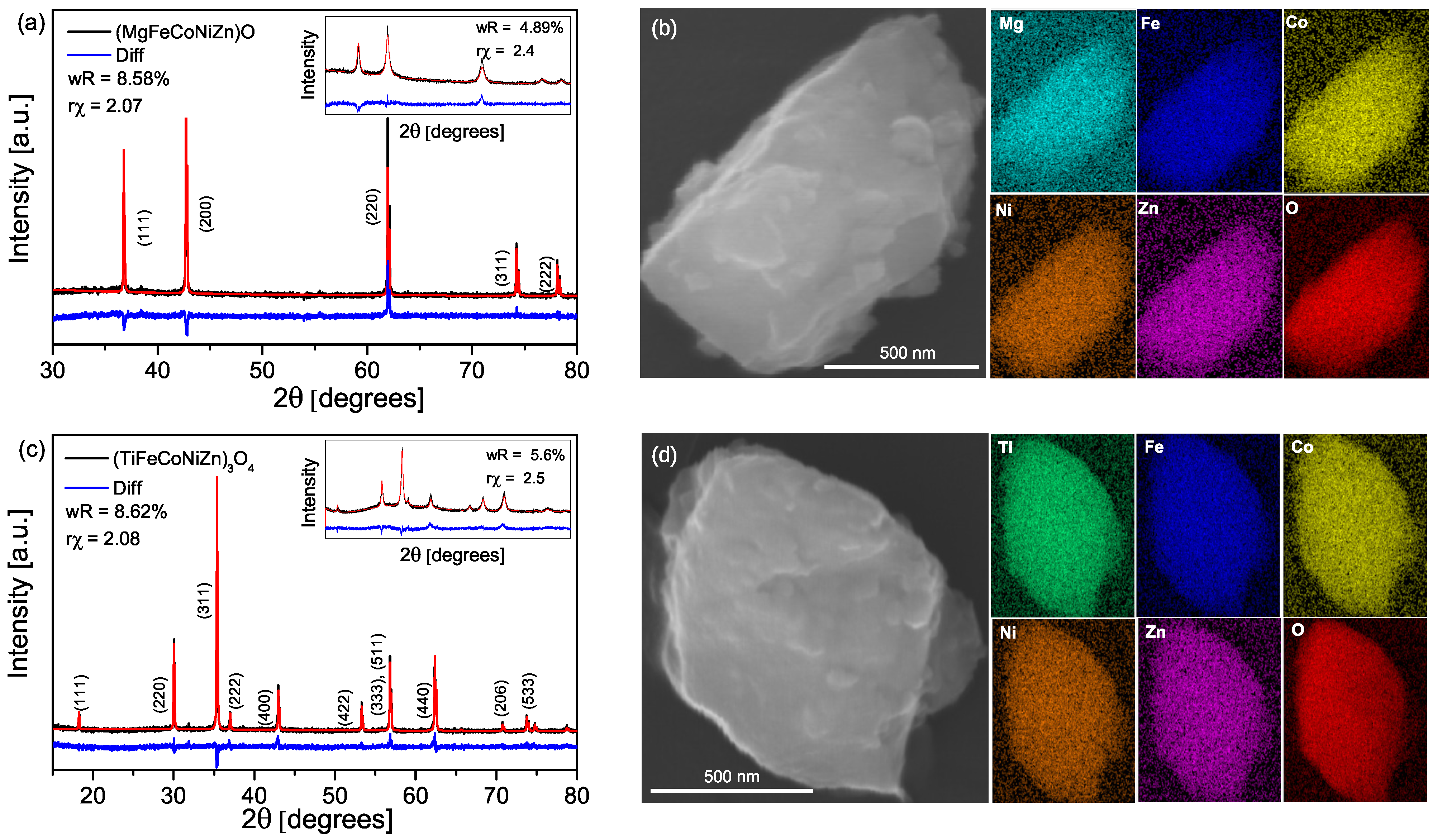
3.1. Structural Characterization

Figure 1a,c show the XRD results of the sintered and nanostructured (figure inset) high-entropy oxides. The (MgFeCoNiZn)O and (TiFeCoNiZn) 3 O 4 , hereafter called HEOR and HEOS, can be indexed as cubic rock salt (Fm-3m) and spinel (Fd-3m) structures, respectively. Both materials remain single-phase after the nanostructuring step. The lattice parameters calculated from the Pawley refinement remain the same after the final nanostructuring, a H E O R = 4.23 ± 0.01 Å and a H E O S = 8.41 ± 0.01 Å. These lattice parameters fall in the middle of those of reference compounds of the individual elements or combinations thereof (Table S2). The average crystallite size extracted from the Pawley refinement is approximately 150 nm for both nanostructured materials. The SEM images (Figure 1b,d) show an average particle of ∼ 1 μ m after nanostructuring, indicating that the typical particle contains many crystallites. The elemental mapping confirms that all the metals are distributed uniformly throughout the particles. In the rock salt structure, the metals share the same octahedrally-coordinated lattice site. In the spinel case, there are two available positions for the metals, one tetrahedral and one octahedral. Each metal’s choice of lattice position is driven primarily by the crystal field stabilization, which is very difficult to predict in this case [26]. Due to the effect of entropy stabilization, it is likely that the metals are mixed in between both positions.

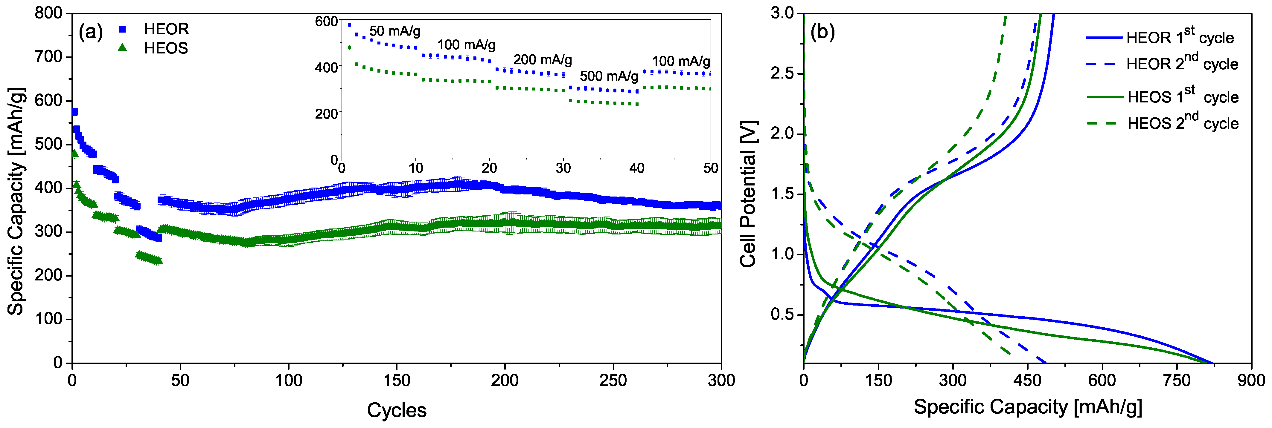
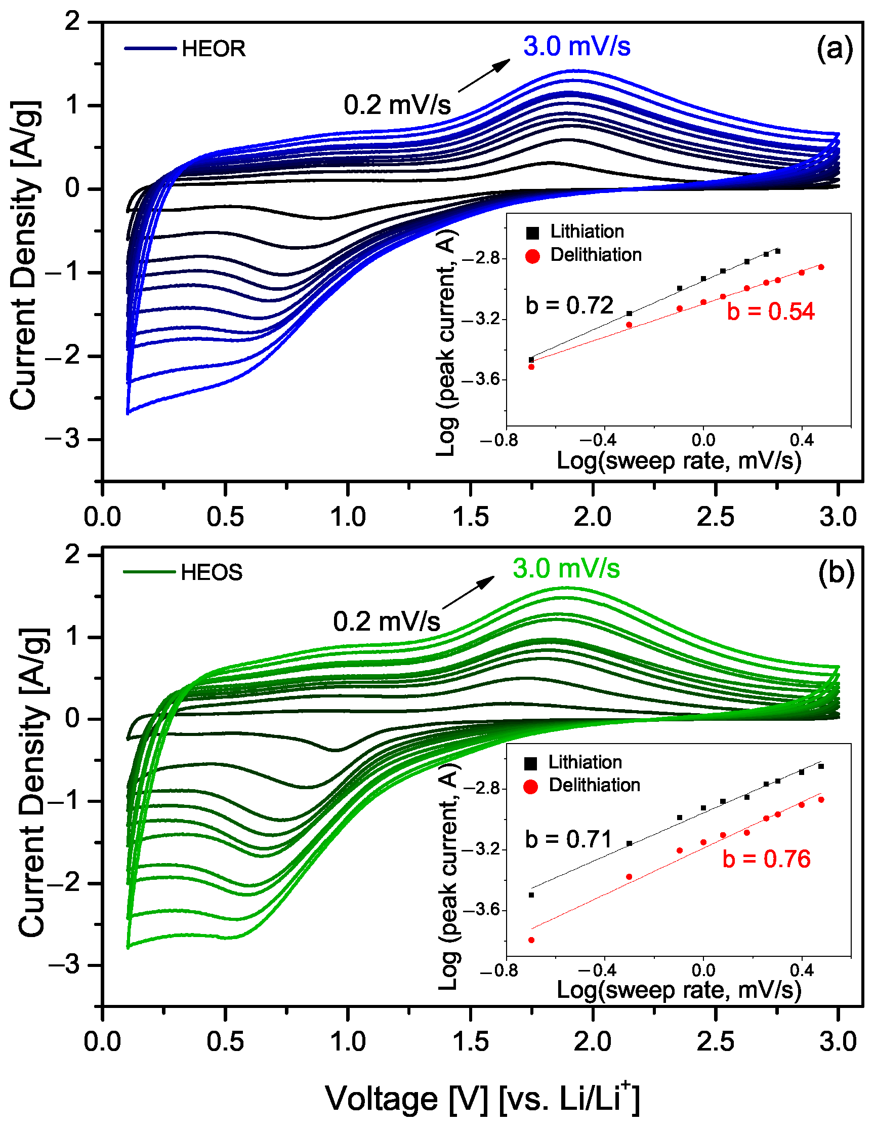
3.2. Electrochemical Characterization

It is expected that Fe, Co, Ni, and Zn act as electrochemically active species in the reaction, being reduced to their metallic state. For the HEOR, all the metals start in an average state of +2 due to the rock salt structure, and the reactions Fe + 2 Fe 0 , Co + 2 Co 0 , Ni + 2 Ni 0 , Zn + 2 Zn 0 can deliver up to 625 mAh/g, in theory. The HEOS, on the other hand, has a mixture of oxidation states, with twice as many octahedral sites as tetrahedral sites. Considering the same active species, and depending on whether Ti is in the +4 or +3 state, the compound can deliver between 636 mAh/g and 704 mAh/g of theoretical capacity. Mg, in the HEOR, and Ti, in the HEOS, are expected to act as structure formers and do not participate directly in the electrochemical conversion reaction. Although the spinel structure has more oxygen and higher molecular weight per mole of metal ions than the rock salt, it can also contribute more electrons to the conversion reaction, contributing to a higher theoretical capacity.
Experimentally, the initial specific capacity of the HEOR (Figure 2a) reaches 575 mAh/g, while the highest capacity for HEOS has a specific capacity of 478 mAh/g at 50 mA/g current density. For both materials, the capacity decreases with increasing current density reaching 304 mAh/g and 246 mAh/g, respectively, at a current density of 500 mA/g. Long-term cycling has been carried out at 100 mA/g current density, where similar patterns were observed on both materials—capacity faded slowly reaching a minimum values of 350 and 275 mAh/g at around 80 cycles followed by an increase in capacity with maximum at 150 cycles, hitting 410 mAh/g and 320 mAh/g, and then slowly decreasing again, reaching 360 mAh/g and 320 mAh/g after 300 cycles. The gradual increase in capacity between cycle 80 and 150 is commonly observed in conversion anodes made with simple metal oxides and the high entropy oxides. The effect is attributed by various authors to different causes. Lin et al. [27] consider the increase as due to an activation process associated with size refinement of the crystallites during conversion while Zhang et al. [28] claim that the electrode undergoes a reorganization that increases the kinetics and capacity of the conversion reaction while reducing the potential. A third possibility is that repeated cycling serves to refine the metal nanoparticle nanostructure and increase the pseudocapacitive portion of the overall capacity suggested by Chen et al. [29]. The HEOS shows remarkable stability after reaching steady value at ∼150 cycles and maintaining average capacity of 320 mAh/g until the end of the cycling routine. The difference in specific capacity between the HEOR and HEOS decreases with increasing cycling rate, changing from ∼117 mAh/g at 50 mA/g to ∼58 mAh/g at 500 mA/g, showing a better response of the HEOS at higher charging/discharging current densities. This could be due to a difference in conductivity of the HEOR and HEOS electrodes due to the inactive metals, MgO and TiO 2 , respectively.
Figure 2b shows the voltage profile of HEOR and HEOS for the first two cycles. Both electrodes behave similarly, having a huge drop of specific capacity during the 1st cycle, but maintaining the characteristic features of a reversible conversion reaction subsequently. During the 1st lithiation, the HEOR reaches a specific capacity of 820 mA/g, while the HEOS 805 mAh/g, both higher than their respective theoretical capacities. This phenomenon is mainly explained due to the complete electrochemical conversion reaction of active species and the SEI layer formation on the anode [30]. The 1st delithiation shows an irreversibility of 61% and 58% for the HEOR and HEOS, reaching a specific capacity of 575 mAh/g and 478 mAh/g, respectively. Both compounds demonstrate similar cell potentials, being 0.7 V and 0.6 V, for the HEOR and HEOS, during the first cycle, and 1.1 V for both electrodes in the 2nd cycle. The difference in specific capacity during the first lithiation and delithiation, and the change in reaction potential between the first two cycles, indicate that some of the active species are not returning to their initial oxidized state upon delithiation. This, along with the likelihood of SEI formation, results in only partial reversibility of the electrochemical reaction in the first cycles.
According to the recent reports on high-entropy oxides as LIB anodes, the presence of metallic species after the conversion reaction can also contribute to a pseudocapacitive behavior of the electrode [15,16,19]. Cyclic-voltammetry (CV) can be used to characterize this behavior by using different voltage sweep rates over the same voltage window, and fitting a logarithmic function to the peak of the sweep currents. This approach can separate the faradaic and non-faradaic contributions to the reaction by calculating the slope, b, of the logarithmic plot of peak current vs. sweep rate. Figure 3 shows the CV for the HEOR (a) and HEOS (b) at different scan rates and the plot of the logarithm of sweep rate vs. the logarithm of the peak current in the respective insets. Both compounds have an intermediate behavior between purely diffusive ( b = 0.5 ) and pseudocapacitive ( b = 1 ). The b coefficient for the lithiation region is 0.72 and 0.71 for the HEOR and HEOS, respectively, and 0.54 and 0.76 for the delithiation region, respectively. This intermediate behavior indicates a pseudocapacitive contribution to the storage capacity of the electrodes that adds capacity to the electrochemical conversion reaction. Still, it is very difficult to separate the electrochemical contribution of different metals in both compounds, as their CV shows unique and broad redox peaks at each of the charge/discharge steps.

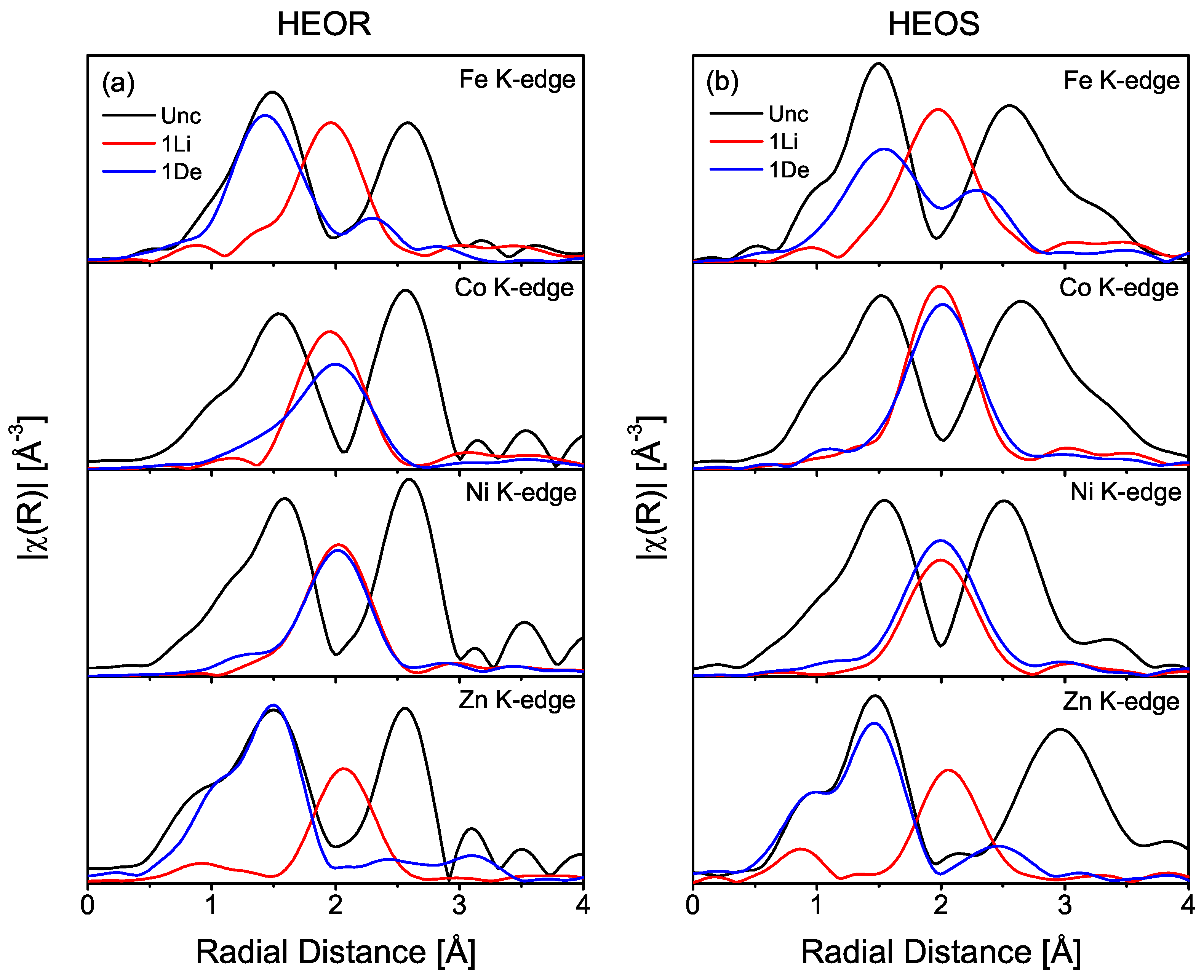
3.3. X-ray Absorption Spectroscopy Analysis

In the uncycled state, the XANES spectrum for Co (Figures S4 and S8) and Zn (Figures S6 and S10) are clearly in a +2 state in both HEOR and HEOS when compared to standard reference compounds. The XANES spectrum for Ni (Figures S5 and S9) are shifted to slightly higher energies than the Ni + 2 (NiO) reference but show the same fine structure. The Fe edge (Figures S3 and S7) for both HEOR and HEOS is shifted close to the Fe + 3 reference (Fe 2 O 3 ), with the shape closely resembling that of the Fe 3 O 4 XANES.
The Fourier Transform of the EXAFS for Fe, Co, Ni, and Zn K-edges (Figure 4) shows the changes in the local structure between the uncycled electrode and the 1st lithiated and 1st delithiated states for both rock salt (HEOR) and spinel (HEOS) compounds. Initially, all metals in the HEOR show a similar structure (in black), composed of two well-shaped peaks: peak at 1.5 Å is related to the octahedral oxygen shell around the absorbing cation position, while the peak at ∼2.6 Å is attributed to the 2nd metallic shell.
The HEOS, on the other hand, has two different sites available for the metallic species, which makes it more difficult to identify their chemical environment. The A site, on the AB 2 O 4 spinel structure, is located in a tetrahedral geometry, while the B site is octahedral. All metals in its composition can exist in either geometry, thus their average coordination can be expected to be in between 4 and 6. Due to entropy stabilization, all metals are likely to be randomly and homogeneously distributed on both sites.
During the 1st lithiation, Fe, Co, Ni, and Zn are all reduced to their metallic states as can be seen by the single peak around 2 Å, which is the metallic local structure signature (Figure 4). In the 1st delithiated state, Zn and Fe show the highest degree of reversibility back to an oxidized state as evidenced by re-appearance of the strong metal–oxygen bond peak at 1.5 Å. Co and Ni show very minor re-oxidation (the shoulder on the short distance side of the metallic peak). The XANES data for both HEOR and HEOS presented on the right side of Figures S3–S10 are consistent with these observations and show the spectra for the 100th cycle as well. The Ni (Figures S5 and S9) and Co (Figures S4 and S8) edges shift to the Ni 0 and Co 0 positions on 1st lithiation show little recovery upon delithiation, completely losing the white line by the 100th cycle. The Fe (Figures S3 and S7) and Zn (Figures S6 and S10) show significant changes between lithiated and delithiated states even to the 100th cycle.
In order to quantify those changes, EXAFS fits of the local structure are performed for the 1st and 100th lithiated and delithiated cycles at the Fe, Co, Ni, and Zn edges. The fits use two paths to model local structure, a TM–O path and a TM–M path, where TM = Fe, Co, Ni, and Zn and M is a general scattering metal. Ni was chosen as M for the models as a representative element with the average scattering properties of the TMs in these compounds. The TM–O paths in the EXAFS fits were calculated using the structural data obtained from the rock salt and spinel Pawley fits. The spinel structure has two possible TM–O paths from the tetrahedral and octahedral metal sites; however, only a single path was needed to fit all the HEOS spectra. The fitting results are presented in Table S3 for HEOR and Table S4 for HEOS.

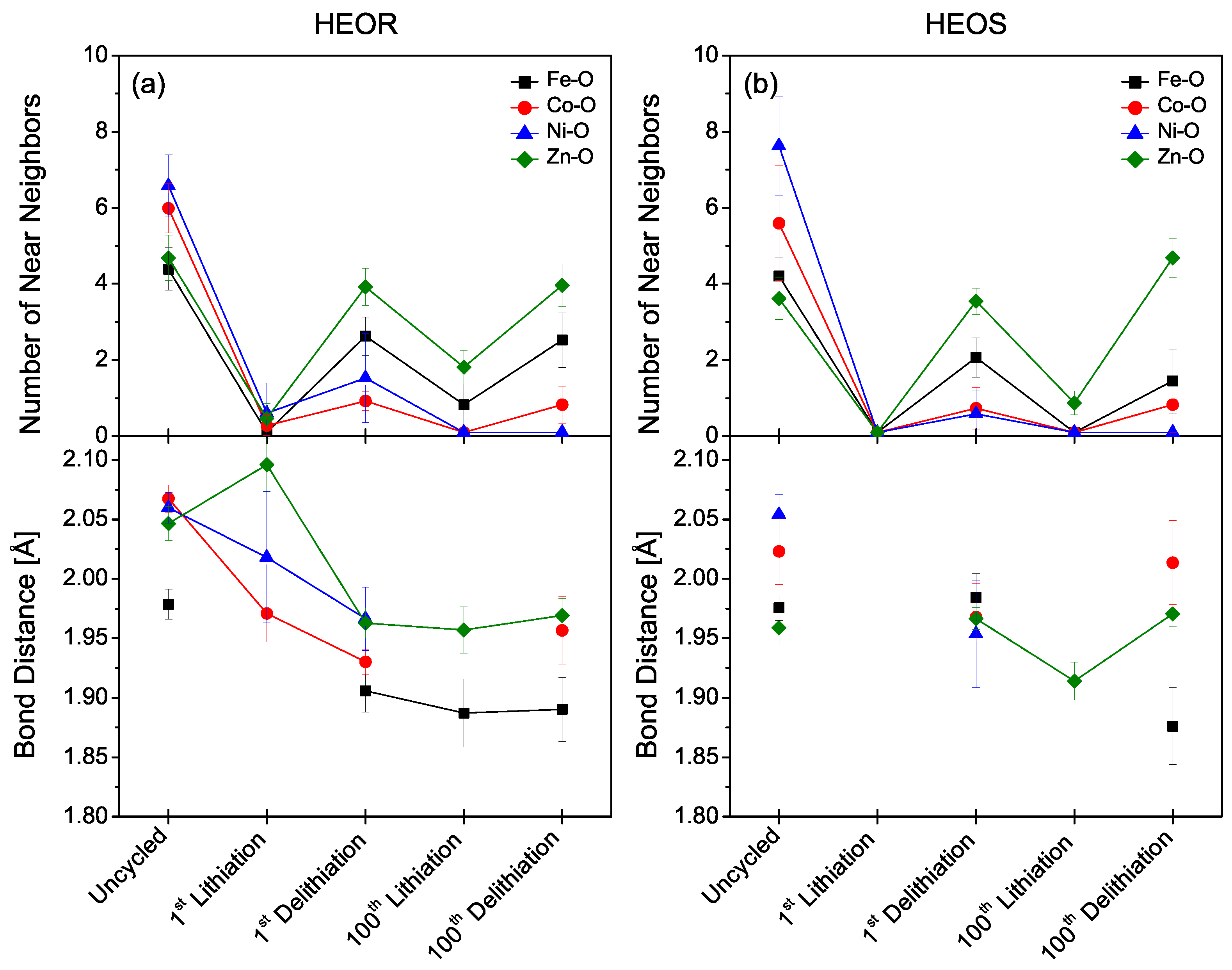
3.3.1. TM–Oxygen Model

Figure 5 shows the fit results detailed in Tables S3 and S4 for the TM–oxygen path in uncycled, 1st lithiated, 1st delithiated, 100th lithiated and 100th delithiated states for Fe, Co, Ni, and Zn. In the uncycled state, the number of near neighbors for Co and Ni in the HEOR are close to 6, consistent with an octahedral environment while the Fe and Zn fits give an oxygen coordination number close to 4, indicating that there could be defect structures present in the rock salt structure. The calculated bond distances for Co, Ni, and Zn in the HEOR deviate only slightly from one-half the lattice parameter obtained in the Pawley refinement. The bond distance for Fe, however, is significantly shorter and consistent with its 4-fold coordination. For HEOS, the bond length and coordination numbers for Fe and Zn suggest that they preferentially occupy the tetrahedral sites of the spinel structure, while Co and Ni sit in the octahedral sites.
During the 1st lithiation the number of oxygens around the Co, Ni, and Zn in the HEOR decreases to less than one, and Fe-O neighbors are completely absent, evidence of a reduced environment and destruction of the initial rock salt structure. In the HEOS, TM–oxygen bonds are absent for all four metals in the 1st lithiated state, which means that Fe, Co, Ni, and Zn were completely reduced to their metallic state and the spinel structure is no longer present.
Upon the 1st delithiation, the oxygen neighbors return to all four metals (Fe, Co, Ni, and Zn) in both HEOR and HEOS compounds. As can be seen from the number of near neighbors shown in Figure 5, Zn shows a higher degree of re-oxidation and electrochemical activity followed by Fe, Ni, and Co, in both HEOR and HEOS consistent with the redox conversion activity decreasing in the order of Zn > Fe > Co > Ni. After 100 cycles, Zn, Fe, and Co still show some reversibility with the number of TM–O bonds decreasing in the lithiated state and increasing in the delithiated state. Ni–O bonds completely disappear in both 100th lithiated and delithated states. TM–O distances fluctuate significantly in the initial cycling, consistent with major material restructuring, but remain fairly constant after extended material cycling.

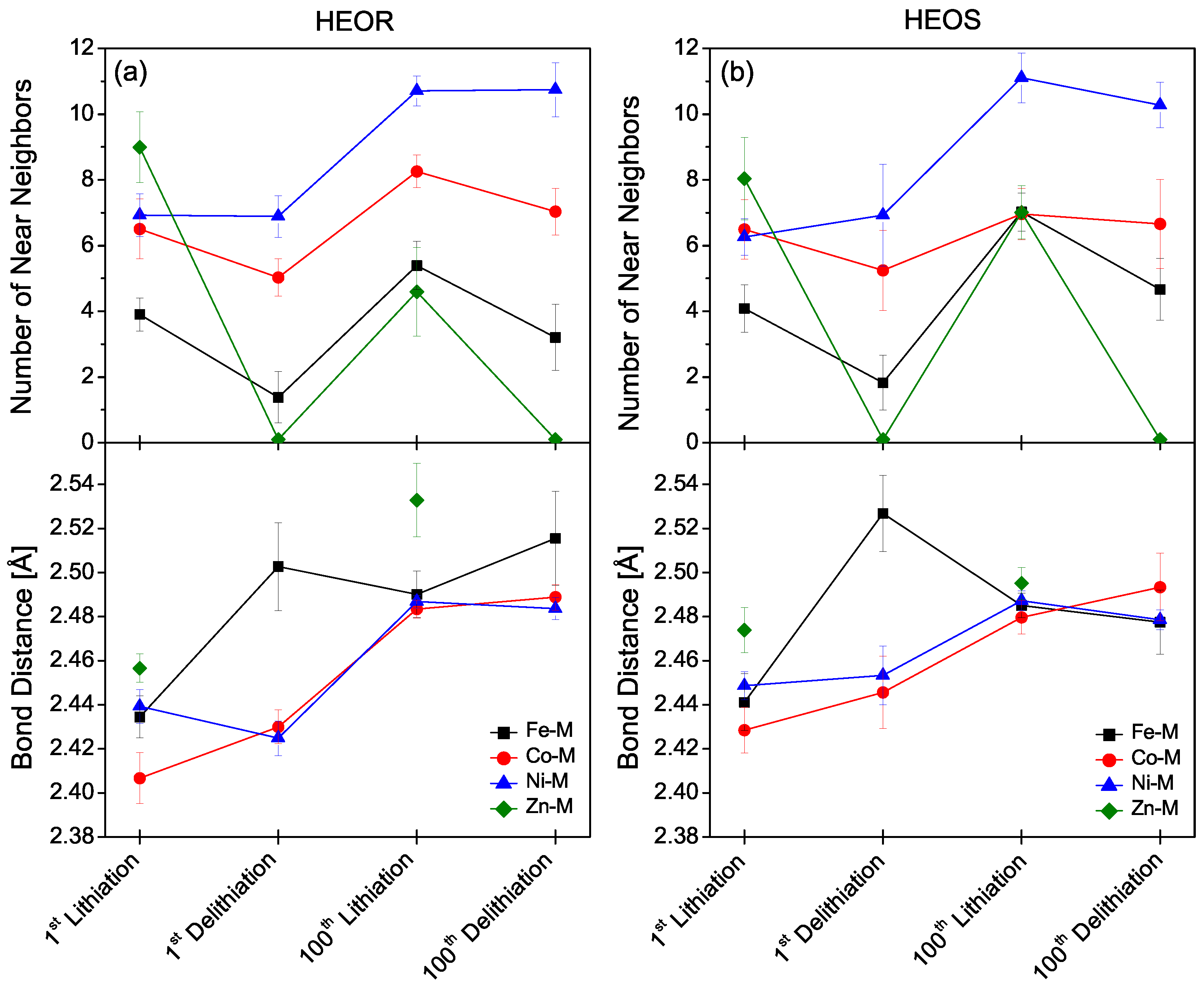
3.3.2. TM–Metal Model

The EXAFS fit results of the TM–metal path show that, in the 1st lithiation, conversion of high entropy oxides to metallic Fe, Co, Ni, and Zn occurs to different degrees (Figure 6 and Tables S3 and S4). For both compounds, the respective number of metal near neighbors seems to follow the same trend. Zn has the largest number of near neighbors of ∼9 and ∼8 for HEOR and HEOS, respectively. On the other hand, Fe has the smallest values, being ∼4 for both the HEOR and HEOS. Co has ∼6.5 metal near neighbors for both HEOR and HEOS and Ni has ∼6.9 and ∼6.2 metal near neighbors for HEOR and HEOS, respectively, which are average between the Zn and Fe values. At 1st delithiation, the conversion redox activity of metals decreases in the series Zn > Fe > Co > Ni and the number of metal near neighbors of Ni is unchanged. For both HEOR and HEOS, the Zn–M bond completely disappears even at the 100th delithiation, showing the remarkable reversibility of Zn conversion in these compounds. Fe–M bonds are still present in both 1st and 100th delithiated states, indicating incomplete conversion, but the number of nearest neighbors decreases from ∼4 to ∼1.4 and ∼1.8 for HEOR and HEOS, respectively, with modest growth in near neighbor numbers by the 100th cycle. Co and Ni show only small changes in the number of metal near neighbors on delithiation, but the total number of TM–M near neighbors grows by the 100th cycle to ∼7.5 for Co and ∼10.5 for Ni. It should be noted that this general increase in the number of TM–M near neighbors in both materials after 100 cycles is consistent with the observed decrease in TM–O bonds.
These results suggest that the structure of both HEOR and HEOS after the initial lithiation is very similar and consists of slowly growing metal nanoparticles containing primarily Ni and Co but, with some Fe, and a significant amount of the Fe and all of the Zn participating in redox reactions all the way through the 100th cycle. While the Mg in HEOR cannot be probed with XAS, the Ti K-edge in HEOS is accessible and can provide clues as to the role of these two presumably inactive metals.

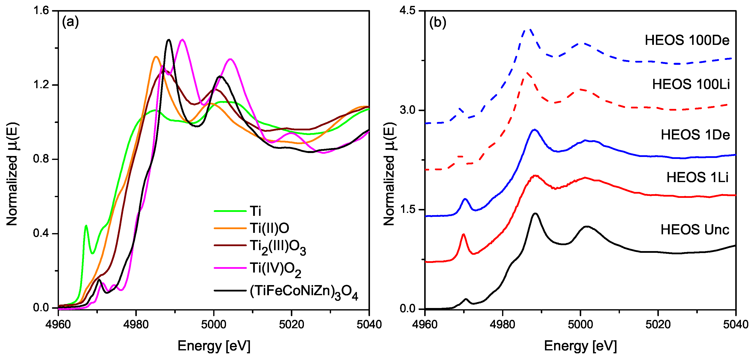
3.3.3. Titanium K-Edge in the HEOS Electrode

In comparison to Ti reference standards, the position of the Ti K-edge XANES suggests that Ti is initially close to a +4 state, but with a shape similar to that of the TiO rock salt standard (Figure 7). As the electrodes are cycled, the shape and position of the Ti XANES remain substantially unchanged, although some of the fine structure features visible initially are smoothed out by the 100th cycle. The Fourier Transform of the Ti EXAFS (Figure S19) is consistent with the Ti remaining in an oxidized state throughout the cycling, albeit with broadening and attenuation of both the first shell Ti–O and Ti–M peaks. The first shell EXAFS fit to a Ti–O path (Table S5) is consistent, despite large estimated standard deviations, with 6-fold coordination of Ti throughout the cycling [31]. Like the Mg in HEOR, Ti in HEOS clearly has a structure forming role which keeps the metal nanoparticles appearing during the conversion process isolated, slowing their growth, and prolonging the cycle life of the electrode.

4. Conclusions

The XANES and EXAFS local structural analysis reveals that the active elements, Fe, Co, Ni, and Zn behave in substantially identical ways for both HEOR and HEOS. Co and Ni form metallic nanoparticles that grow slowly over cycling time, Fe and Zn continue to be redox active in the conversion process throughout the 100 cycles observed with Zn being fully reduced and re-oxidized each cycle. Mg and Ti do not participate in the electrochemical reaction but fulfill a critical role in maintaining structural integrity of the electrode, ionic conductivity for Li + , and separation of the metal nanoclusters and thus slowing capacity fade. The cycling performance of the HEOR and HEOS electrodes are substantially the same for the 300 cycles investigated with a slight difference in specific capacity (Figure 2a). This difference all but vanishes by noting that HEOR has a single mole oxygen per mole of metal atoms while HEOS has 1.33 moles of oxygen per mole of metal atoms. If the specific capacity is recalculated in terms of molar capacity, the maximum capacities at the 175th cycle are 25.2 ± 0.6 Ah/mol for HEOR and 24.8 ± 1.6 Ah/mol for HEOS (Figure S20). This provides additional evidence that the initial long-range crystallographic structure of an entropy-stabilized oxide conversion anode is not as important for the redox mechanism and ultimate cycling performance of the material. Rather, the critical components for the superior performance compared to single element metal oxides are the amount of active metal ions in the mixture and the initial random spatial distribution of the metal ions resulting from entropy-stabilization.

Supplementary Materials

The following supporting information can be downloaded at: https://www.mdpi.com/article/10.3390/batteries9020115/s1, Figure S1: Rock-salt and spinel structures; Figure S2: Comparison of cyclic voltammetry; Figures S3–S10: Fe, Co, Ni, and Zn XANES spectra of HEOR and HEOS electrodes; Figures S11–S18: Fe, Co, Ni, and Zn EXAFS fits for HEOR and HEOS electrodes; Figure S19: Ti EXAFS spectra of HEOS electrodes; Figure S20: Specific molar capacity for HEOR and HEOS; Table S1: Details of Pawley refinements; Table S2: Comparison of HEOR and HEOS lattice parameters with isostructural compounds including References [32,33,34,35,36,37,38,39]; Table S3: Fe, Co, Ni, and Zn edge EXAFS fit results for HEOR electrodes; Table S4: Fe, Co, Ni, and Zn edge EXAFS fits for HEOS electrodes; Table S5: Ti edge EXAFS fits for HEOS electrodes.

Author Contributions

Conceptualization, C.U.S. and O.J.B.J.M.; methodology, C.U.S. and O.J.B.J.M.; validation, E.V.T.; investigation, O.J.B.J.M. and M.D.W.; resources, C.U.S.; data curation, C.U.S. and O.J.B.J.M.; writing—original draft preparation, O.J.B.J.M.; writing—review and editing, E.V.T. and C.U.S.; visualization, C.U.S. and O.J.B.J.M.; supervision, C.U.S.; project administration, C.U.S. and O.J.B.J.M.; funding acquisition, C.U.S. All authors have read and agreed to the published version of the manuscript.

Funding

This work was supported by the Illinois Institute of Technology Duchossois Leadership Professors Program. MRCAT operations are supported by the Department of Energy and the MRCAT member institutions. This research used resources of the Advanced Photon Source, a U.S. Department of Energy (DOE) Office of Science User Facility operated for the DOE Office of Science by Argonne National Laboratory under Contract No. DE-AC02-06CH11357.

Institutional Review Board Statement

Not applicable.

Informed Consent Statement

Not applicable.

Data Availability Statement

The data presented in this study are available on request from the corresponding author.

Acknowledgments

The authors wish to thank the assistance of High School student teams from Maine South High School under the Exemplary Student Research Program and Stevenson High School under the STEM Professionals As Resource Knowledge program who assisted in sample preparation.

Conflicts of Interest

The authors declare no conflict of interest. The funders had no role in the design of the study; in the collection, analyses, or interpretation of data; in the writing of the manuscript; or in the decision to publish the results.

References

  1. Bruce, P.; Scrosati, B.; Tarascon, J.M. Nanomaterials for rechargeable lithium batteries. Angew. Chem. Int. Ed. 2008, 47, 2930–2946. [Google Scholar] [CrossRef]
  2. Goodenough, J.B.; Kim, Y. Challenges for rechargeable Li batteries. Chem. Mater. 2009, 22, 587–603. [Google Scholar] [CrossRef]
  3. Li, M.; Lu, J.; Chen, Z.; Amine, K. 30 Years of lithium-ion batteries. Adv. Mater. 2018, 30, 1800561. [Google Scholar] [CrossRef] [PubMed]
  4. Tarascon, J.M.; Armand, M. Issues and challenges facing rechargeable lithium batteries. Nature 2001, 414, 359–367. [Google Scholar] [CrossRef] [PubMed]
  5. Lu, J.; Chen, Z.; Pan, F.; Cui, Y.; Amine, K. High-performance anode materials for rechargeable lithium-ion batteries. Electrochem. Energy Rev. 2018, 1, 35–53. [Google Scholar] [CrossRef]
  6. Sarkar, A.; Velasco, L.; Wang, D.; Wang, Q.; Talasila, G.; de Biasi, L.; Kübel, C.; Brezesinski, T.; Bhattacharya, S.S.; Hahn, H.; et al. High entropy oxides for reversible energy storage. Nat. Commun. 2018, 9, 3400. [Google Scholar] [CrossRef]
  7. Rost, C.M.; Sachet, E.; Borman, T.; Moballegh, A.; Dickey, E.C.; Hou, D.; Jones, J.L.; Curtarolo, S.; Maria, J.P. Entropy-stabilized oxides. Nat. Commun. 2015, 6, 8485. [Google Scholar] [CrossRef]
  8. Zhang, R.Z.; Reece, M.J. Review of high entropy ceramics: Design, synthesis, structure and properties. J. Mater. Chem. A 2019, 7, 22148–22162. [Google Scholar] [CrossRef]
  9. Oses, C.; Toher, C.; Curtarolo, S. High-entropy ceramics. Nat. Rev. Mater. 2020, 5, 295–309. [Google Scholar] [CrossRef]
  10. Musicó, B.L.; Gilbert, D.; Ward, T.Z.; Page, K.; George, E.; Yan, J.; Mandrus, D.; Keppens, V. The emergent field of high entropy oxides: Design, prospects, challenges, and opportunities for tailoring material properties. APL Mater. 2020, 8, 040912. [Google Scholar] [CrossRef] [Green Version]
  11. Sarkar, A.; Wang, Q.; Schiele, A.; Chellali, M.R.; Bhattacharya, S.S.; Wang, D.; Brezesinski, T.; Hahn, H.; Velasco, L.; Breitung, B. High-entropy oxides: Fundamental aspects and electrochemical properties. Adv. Mater. 2019, 31, 1806236. [Google Scholar] [CrossRef] [PubMed]
  12. Qiu, N.; Chen, H.; Yang, Z.; Sun, S.; Wang, Y.; Cui, Y. A high entropy oxide (Mg0.2Co0.2Ni0.2Cu0.2Zn0.2O) with superior lithium storage performance. J. Alloys Compd. 2019, 777, 767–774. [Google Scholar] [CrossRef]
  13. Lökçü, E.; Toparli, Ç.; Anik, M. Electrochemical performance of (MgCoNiZn)1–xLixO high-entropy oxides in lithium-ion batteries. ACS Appl. Mater. Interfaces 2020, 12, 23860–23866. [Google Scholar] [CrossRef]
  14. Chen, T.Y.; Wang, S.Y.; Kuo, C.H.; Huang, S.C.; Lin, M.H.; Li, C.H.; Chen, H.Y.T.; Wang, C.C.; Liao, Y.F.; Lin, C.C.; et al. In operando synchrotron X-ray studies of a novel spinel (Ni0.2Co0.2Mn0.2Fe0.2Ti0.2)3O4 high-entropy oxide for energy storage applications. J. Mater. Chem. A 2020, 8, 21756–21770. [Google Scholar] [CrossRef]
  15. Chen, H.; Qiu, N.; Wu, B.; Yang, Z.; Sun, S.; Wang, Y. A new spinel high-entropy oxide (Mg0.2Ti0.2Zn0.2Cu0.2Fe0.2)3O4 with fast reaction kinetics and excellent stability as an anode material for lithium ion batteries. RSC Adv. 2020, 10, 9736–9744. [Google Scholar] [CrossRef] [PubMed]
  16. Wang, D.; Jiang, S.; Duan, C.; Mao, J.; Dong, Y.; Dong, K.; Wang, Z.; Luo, S.; Liu, Y.; Qi, X. Spinel-structured high entropy oxide (FeCoNiCrMn)3O4 as anode towards superior lithium storage performance. J. Alloys Compd. 2020, 844, 156158. [Google Scholar] [CrossRef]
  17. Nguyen, T.X.; Patra, J.; Chang, J.K.; Ting, J.M. High entropy spinel oxide nanoparticles for superior lithiation–delithiation performance. J. Mater. Chem. A 2020, 8, 18963–18973. [Google Scholar] [CrossRef]
  18. Xiao, B.; Wu, G.; Wang, T.; Wei, Z.; Sui, Y.; Shen, B.; Qi, J.; Wei, F.; Meng, Q.; Ren, Y.; et al. High entropy oxides (FeNiCrMnX)3O4 (X = Zn, Mg) as anode materials for lithium ion batteries. Ceram. Int. 2021, 47, 33972–33977. [Google Scholar] [CrossRef]
  19. Tian, K.H.; Duan, C.Q.; Ma, Q.; Li, X.L.; Wang, Z.Y.; Sun, H.Y.; Luo, S.H.; Wang, D.; Liu, Y.G. High-entropy chemistry stabilizing spinel oxide (CoNiZnXMnLi)3O4 (X = Fe, Cr) for high-performance anode of Li-ion batteries. Rare Met. 2021, 41, 1265–1275. [Google Scholar] [CrossRef]
  20. Zheng, Y.; Wu, X.; Lan, X.; Hu, R. A spinel (FeNiCrMnMgAl)3O4 high entropy oxide as a cycling stable anode material for Li-ion batteries. Processes 2021, 10, 49. [Google Scholar] [CrossRef]
  21. Poizot, P.; Laruelle, S.; Grugeon, S.; Dupont, L.; Tarascon, J.M. Nano-sized transition-metal oxides as negative-electrode materials for lithium-ion batteries. Nature 2000, 407, 496–499. [Google Scholar] [CrossRef]
  22. Toby, B.H.; Dreele, R.B.V. GSAS-II: The genesis of a modern open-source all purpose crystallography software package. J. Appl. Crystallogr. 2013, 46, 544–549. [Google Scholar] [CrossRef]
  23. Kropf, A.J.; Katsoudas, J.; Chattopadhyay, S.; Shibata, T.; Lang, E.A.; Zyryanov, V.N.; Ravel, B.; McIvor, K.; Kemner, K.M.; Scheckel, K.G.; et al. The New MRCAT (Sector 10) bending magnet beamline at the Advanced Photon Source. AIP Conf. Proc. 2010, 1234, 299–302. [Google Scholar] [CrossRef]
  24. Newville, M. IFEFFIT: Interactive XAFS analysis and FEFF fitting. J. Synchrotron Radiat. 2001, 8, 322–324. [Google Scholar] [CrossRef] [PubMed]
  25. Ravel, B.; Newville, M. ATHENA, ARTEMIS, HEPHAESTUS: Data analysis for X-ray absorption spectroscopy using IFEFFIT. J. Synchrotron Radiat. 2005, 12, 537–541. [Google Scholar] [CrossRef]
  26. Burdett, J.K.; Price, G.D.; Price, S.L. Role of the crystal-field theory in determining the structures of spinels. J. Am. Chem. Soc. 1982, 104, 92–95. [Google Scholar] [CrossRef]
  27. Lin, Y.M.; Abel, P.R.; Heller, A.; Mullins, C.B. α-Fe2O3 nanorods as anode material for lithium ion batteries. J. Phys. Chem. Lett. 2011, 2, 2885–2891. [Google Scholar] [CrossRef]
  28. Zhang, J.; Lee, G.H.; Lau, V.W.; Zou, F.; Wang, Y.; Wu, X.; Wang, X.L.; Chen, C.L.; Su, C.J.; Kang, Y.M. Electrochemical grinding-induced metallic assembly exploiting a facile conversion reaction route of metal oxides toward Li ions. Acta Mater. 2021, 211, 116863. [Google Scholar] [CrossRef]
  29. Chen, H.; Qiu, N.; Wu, B.; Yang, Z.; Sun, S.; Wang, Y. Tunable pseudocapacitive contribution by dimension control in nanocrystalline-constructed (Mg0.2Co0.2Ni0.2Cu0.2Zn0.2)O solid solutions to achieve superior lithium-storage properties. RSC Adv. 2019, 9, 28908–28915. [Google Scholar] [CrossRef]
  30. Ng, B.; Faegh, E.; Lateef, S.; Karakalos, S.G.; Mustain, W.E. Structure and chemistry of the solid electrolyte interphase (SEI) on a high capacity conversion-based anode: NiO. J. Mater. Chem. A 2021, 9, 523–537. [Google Scholar] [CrossRef]
  31. Farges, F.; Brown, G.E.; Rehr, J.J. Ti K-edge XANES studies of Ti coordination and disorder in oxide compounds: Comparison between theory and experiment. Phys. Rev. B 1997, 56, 1809–1819. [Google Scholar] [CrossRef]
  32. Sasaki, S.; Fujino, K.; Takéuchi, Y. X-ray determination of electron-density distributions in oxides, MgO, MnO, CoO, and NiO, and atomic scattering factors of their constituent atoms. Proc. Japan Acad. Ser. B 1979, 55, 43–48. [Google Scholar] [CrossRef]
  33. Karzel, H.; Potzel, U.; Potzel, W.; Moser, J.; Schäfer, C.; Steiner, M.; Peter, M.; Kratzer, A.; Kalvius, G. X-Ray diffractometer for high pressure and low temperatures. Mater. Sci. Forum 1991, 79–82, 419–426. [Google Scholar] [CrossRef]
  34. Fjellvåg, H.; Grønvold, F.; Stølen, S.; Hauback, B. On the crystallographic and magnetic structures of nearly stoichiometric iron monoxide. J. Solid State Chem. 1996, 124, 52–57. [Google Scholar] [CrossRef]
  35. Will, G.; Masciocchi, N.; Parrish, W.; Hart, M. Refinement of simple crystal structures from synchrotron radiation powder diffraction data. J. Appl. Crystallogr. 1987, 20, 394–401. [Google Scholar] [CrossRef]
  36. Fleet, M.E. The structure of magnetite: Symmetry of cubic spinels. J. Solid State Chem. 1986, 62, 75–82. [Google Scholar] [CrossRef]
  37. Pailhé, N.; Wattiaux, A.; Gaudon, M.; Demourgues, A. Correlation between structural features and vis–NIR spectra of α-Fe2O3 hematite and AFe2O4 spinel oxides (A=Mg, Zn). J. Solid State Chem. 2008, 181, 1040–1047. [Google Scholar] [CrossRef]
  38. Thota, S.; Reehuis, M.; Maljuk, A.; Hoser, A.; Hoffmann, J.U.; Weise, B.; Waske, A.; Krautz, M.; Joshi, D.C.; Nayak, S.; et al. Neutron diffraction study of the inverse spinels Co2TiO4 and Co2SnO4. Phys. Rev. B 2017, 96, 144104. [Google Scholar] [CrossRef]
  39. da Silva Pedro, S.; López, A.; Sosman, L.P. Zn2TiO4 photoluminescence enhanced by the addition of Cr3+. SN Appl. Sci. 2019, 2. [Google Scholar] [CrossRef] [Green Version]
Figure 1. X-ray powder diffraction data (black), Pawley refinement (red) and their difference (blue) for (a) HEOR and (c) HEOS samples before nanostructuring. The inset images show the nanostructured materials after the final ball milling. SEM images and elemental mapping for typical particles (b) HEOR and (d) HEOS after nanostructuring.
Batteries 09 00115 g001
Figure 2. Electrochemical performance of HEOR (blue) and HEOS (green) by (a) galvanostatic cycling at different cycling rates averaged over four cells with close-up of cycles 1–50 in the inset and (b) the voltage profile of first (solid) and second (dashed) cycles.
Batteries 09 00115 g002
Figure 3. Cyclic voltammetry at different voltage sweep rates: 0.2 darkest shade; 0.5; 0.8; 1.0; 1.2; 1.5; 1.8; 2.0; 2.5, and 3.0 lightest shade mV/sC for (a) HEOR and (b) HEOS. The insets show the linear fits to the logarithmic plots of peak current and sweep rate for both lithiation (black squares) and delithiation (red circles) currents.
Batteries 09 00115 g003
Figure 4. EXAFS spectra in R-space of Fe, Co, Ni, and Zn K-edges for the (a) HEOR and (b) HEOS electrodes in uncycled (black), 1st lithiated (red), and 1st delithiated states (blue).
Batteries 09 00115 g004
Figure 5. TM–O K-edge EXAFS fit results for (a) HEOR and (b) HEOS compounds in uncycled, 1st lithiated, 1st delithiated, 100th lithiated and 100th delithiated states for Fe (black squares), Co (red circles), Ni (blue triangles), and Zn (magenta inverted triangles).
Batteries 09 00115 g005
Figure 6. TM–M K-edge EXAFS fit results for (a) HEOR and (b) HEOS compounds in uncycled, 1st lithiated, 1st delithiated, 100th lithiated and 100th delithiated states for Fe (black squares), Co (red circles), Ni (blue triangles), and Zn (magenta inverted triangles).
Batteries 09 00115 g006
Figure 7. Ti K-edge XANES for uncycled HEOS electrode (black) compared to (a) standard reference samples Ti (green), TiO (orange), Ti 2 O 3 (brown) and TiO 2 (magenta); and (b) electrodes at various states of cycle and charge: 1st lithiation (solid red), 1st delithiation (solid blue), 100th lithiation (dashed red), and 100th delithiation (dashed blue).
Batteries 09 00115 g007
Disclaimer/Publisher’s Note: The statements, opinions and data contained in all publications are solely those of the individual author(s) and contributor(s) and not of MDPI and/or the editor(s). MDPI and/or the editor(s) disclaim responsibility for any injury to people or property resulting from any ideas, methods, instructions or products referred to in the content.

