Review

A Review of Lithium-Ion Battery Failure Hazards: Test Standards, Accident Analysis, and Safety Suggestions

1
College of Mechanical Engineering, University of Shanghai for Science and Technology, Shanghai 200093, China
2
State Key Laboratory of Automotive Safety and Energy, Tsinghua University, Beijing 100084, China
3
School of Criminal Investigation, China People’s Police University, LangFang 065000, China
*
Authors to whom correspondence should be addressed.
Batteries 2022, 8(11), 248; https://doi.org/10.3390/batteries8110248
Submission received: 16 October 2022 / Revised: 7 November 2022 / Accepted: 17 November 2022 / Published: 20 November 2022
(This article belongs to the Collection Advances in Battery Energy Storage and Applications)

Abstract

:
The frequent safety accidents involving lithium-ion batteries (LIBs) have aroused widespread concern around the world. The safety standards of LIBs are of great significance in promoting usage safety, but they need to be constantly upgraded with the advancements in battery technology and the extension of the application scenarios. This study comprehensively reviews the global safety standards and regulations of LIBs, including the status, characteristics, and application scope of each standard. A standardized test for thermal runaway triggering is also introduced. The recent fire accidents in electric vehicles and energy storage power stations are discussed in relation to the upgrading of the rational test standards. Finally, the following four suggestions for improving battery safety are proposed to optimize the safety standards: (1) early warning and cloud alarms for the battery’s thermal runaway; (2) an innovative structural design for a no-fire battery pack; (3) the design of a fire water injection interface for the battery pack; (4) the design of an immersive energy storage power station. This study provides insights for promoting the effectiveness of relevant safety standards for LIBs, thereby reducing the failure hazards.

1. Introduction

Under the dual pressure of environmental protection and the energy crisis, as well as the promotion of the goal of carbon neutrality, energy conservation and emission reduction have become urgent tasks involving all major global economies [1,2,3]. Electric vehicles (EVs) use clean energy to escape from the dependence on petroleum, and effectively reduce the emission of various greenhouse gases. This has become a hot academic and industrial topic and has received extensive attention from governments worldwide [4,5,6]. In recent years, the EV industry has been expanding rapidly, and the sales volume is ever-increasing. Lithium-ion batteries (LIBs) have become the absolute mainstream among all EV power sources due to their advantages, such as their high energy density, excellent life cycle performance, and high charge–discharge efficiency [7,8,9]. The global installed capacity of LIBs in EVs is expected to reach 357.5 GWh in 2022 [10]. In addition, the large-scale utilization of renewable energy is the overwhelming path to achieving deep decarbonization of the electrical power system. In this process, the new energy storage technology represented by electrochemical energy storage has become an important pivot method of continuously increasing the installation proportion of renewable energy. With the development of the electrochemical energy storage industry, the advantages of LIBs for energy storage are now prominent, and they currently account for approximately 75% of the chemical energy storage [11].
To pursue higher specific energy LIBs, cathode materials with high specific energy have been developed, such as NCM111, NCM532, NCM622, and NCM811 [12,13,14]. In addition, manufacturers are using thicker battery cathodes, which can improve the lithium content [15], or thinner separators and thinner current collectors to decrease the non-energized parts of the single cells [16]. The size of each single cell has also become larger and larger, and the ordinary volume of a prismatic battery has increased from 360 cm3 (five years ago) to 1200–1500 cm3 (today), while the capacity of a single cell has increased from 10–20 Ah five years ago to 150–200 Ah. However, the energy density of LIBs is gradually approaching the inherent safety limits of their electrochemical systems [17,18,19]. Once certain abusive conditions break the stability boundaries of the electrochemical system, an LIB is more susceptible to thermal runaway (TR), leading to fire accidents [20,21]. In 2021, China reported more than 3000 EV fire accidents [18]. In the past decade, more than 60 fire accidents in electrochemical energy storage power stations have been reported worldwide [22,23]. The investigation reports show that most of these accidents were caused by TR of the LIBs. The safety of LIBs has become a key factor affecting their sustainable development and has become a social and academic hotspot [24,25,26,27,28].
The state-of-the-art of the research on battery TR is focused on various technologies, mainly divided into two major technical schemes, i.e., active and passive safety technologies [29,30,31,32]. However, few studies have focused on the important issue of battery safety regulations and standards. In the research and development of new cell chemistries, stringent safety test standards are required to evaluate and ensure the usage safety of batteries. However, battery fire accidents still occur even after a battery has passed a series of abuse test standards [33,34]. The reason for this phenomenon is that the abuse conditions of the LIBs may be more serious and unpredictable in practical scenarios, while the relevant safety test standards cannot cover all real situations. Therefore, developing reasonable battery safety test regulations for battery safety evaluations is very important.
There are many safety test regulations and standards for LIBs that are constantly developing and evolving [18,35,36,37,38]. Therefore, it is necessary to comprehensively review and analyze the regulations and test standards related to battery safety. In this study, the typical regulations and standards regarding battery safety tests are comprehensively summarized, and the technical characteristics and application scope of each regulation and standard are compared. Then, through the investigation of the fire accidents involving EVs in 2021 and the fire accidents involving energy storage power stations in the past decade, four valuable suggestions are put forward to improve the test standards regarding battery safety.
The remainder of this paper is organized as follows. Section 2 summarizes the regulations and standards related to the safety of LIBs in detail. Section 3 compares and summarizes the fire accidents involving energy storage power stations and EVs in recent years. Section 4 puts forward four suggestions for standard updating based on the characteristics of fire accidents. Finally, some conclusions are provided in Section 5.

2. Regulations and Standards for Battery Safety

2.1. Overview

2.1.1. Thermal Runaway Process and Fire Behavior

A lithium-ion battery comprises an anode, cathode, separator, electrolyte, collector, and shell, and the lithium-ion is embedded and de-embedded between the anode and cathode during normal operation [39]. The battery charging and discharging process is essentially a chemical reaction inside the battery, which is reversible and stable. However, due to mechanical abuse, thermal abuse, electrical abuse, and other incentives, side effects may occur inside the battery, resulting in abnormal temperature increases and TR [40,41,42,43,44]. Battery TR has been widely reported, and many scholars are exploring the TR mechanism and process [45,46,47,48]. The results show that when battery TR occurs, a series of side reactions occur first on the anode, including the decomposition of SEI and the reaction between the embedded lithium and electrolyte. Subsequently, the separator is closed, contracted, and collapsed, and the anode and cathode are contacted to form a large-scale internal short circuit. In this case, a lot of heat is released. Then, the cathode material is gradually decomposed and oxygen is released, which reacts violently with the cathode material and electrolyte accompanied by a large amount of heat. Finally, the heat release causes the battery to burn or even explode, causing serious safety accidents.
According to the battery TR mechanism, many TR suppression methods have been proposed, which can be roughly divided into three technical paths: intrinsic safety, active safety, and passive safety [49]. Intrinsic safety refers to improving the thermal stability of batteries at the material level and ensuring the battery’s reliability from a design and manufacturing perspective. For example, the fluorinated electrolyte can effectively inhibit the exothermic reaction between the anode and electrolyte [50]. Ceramic-coated, high-temperature-resistant, aramid separators can prevent them from melting under high temperatures, causing the internal short circuit of the battery [51]. In addition, the all-solid-state batteries use stable solid electrolytes instead of flammable organic electrolytes, which is expected to solve the battery safety problem and attract global attention [52]. Active safety refers to the early warning of TR through intelligent control, big data, and other advanced battery management technologies [53,54]. Passive safety means that thermal management is used to restrain heat propagation after the TR of a single battery cell has occurred [55,56,57]. In this process, it is critical to prevent TR from spreading in the battery pack through heat insulation and dissipation.

2.1.2. Standards and Regulations

With the continuous development of LIBs, the corresponding LIB test standards are constantly improved. The various organizations and institutions that make these standards have actively participated in guaranteeing the safety of the battery industry [36,58,59], including the International Organization for Standardization (ISO), the International Electrotechnical Commission (IEC), the Society of Automotive Engineers (SAE), the UL certification body, the China Administration for Standardization (SAC), and the Ministry of Industry and Information Technology of China (MIIT). A large number of standards have been developed to regulate the safety testing of LIBs. Table 1 summarizes the applicable scope and technical characteristics of the general standards for LIBs.
All LIBs must pass a series of safety test standards, and each nationality or region should conduct safety tests according to their domestic standards. These safety tests evaluate the LIBs by simulating extreme situations that may occur during usage. All of the standards have a criterion or hazard rating for judging whether the test sample is qualified or unqualified. Generally, all of the tests must meet the requirement of no fire and no explosion occurring. However, the qualification requirements for specific safety tests may differ, such as the external combustion test, which only requires no explosion to occur. In addition, the requirement in GB 38031-2020 [84] for the TR propagation test upon the battery pack is to provide an alarm signal (used for vehicle thermal alarms to remind passengers of dispersion) 5 min before the TR propagation worsens into the combustion or even explosion of the battery system.
The major causes of the TR of LIBs can be divided Into three categories: mechanical abuse, electrical abuse, and thermal abuse [44,85,86]. Therefore, the safety tests for the relevant standards are mainly categorized into these three types. Accordingly, the safety test terms can be roughly divided into three categories: mechanical tests (such as drop tests, vibration tests, and mechanical shock tests), electrical tests (such as external short circuit tests, overcharge tests, and overdischarge tests), and environmental tests (such as thermal shock cycle tests, damp heat cycle tests, and external fire tests). These test methods are described in detail below.

2.2. Mechanical Tests

The mechanical tests include drop, vibration, mechanical impact, and extrusion tests. The relevant characteristic parameters in each test standard are listed in Table 2.

2.2.1. Drop Test

The drop test simulates a scenario where the battery accidentally falls from a high place. The main method of this test is to let the tested battery fall freely onto the ground from the specified height at a certain angle. The specific test methods in each standard are slightly different, but the safety requirements are that the battery should not ignite or explode. SAE J2464-2021 [72] only involves drop tests on battery packs. The test height should be 1 m or the height specified in the actual field application procedure. The drop test in SAND 2005-3123 [75] is quite special. It stipulates that the drop height shall not exceed 10 m, and the sample must be dropped to a cylindrical steel object with a radius of 150 mm. In UL 2580-2020 [77], the drop test requires the tested sample to drop from a height of at least 1 m to the concrete plane, which is at least 76 mm thick. At least one drop test is not a horizontal drop. In addition, there is a drop test in the test standards for energy storage batteries, which aims to simulate an accidental drop that may occur during battery installation and maintenance. In IEC 63056-2020 [71], drop tests are specified in detail for different weight classes, as listed in Table 3. Battery samples weighing less than 7 kg need to be dropped from a height of 100 cm, battery samples weighing from 7 kg to 20 kg need to be dropped from a height of 100 cm, samples weighing from 20 kg to 50 kg need to be dropped from a height of 50 cm, samples weighing above 50 kg need to be dropped in the form of angular contact or edge contact, samples weighing from 50 kg to 100 kg have a test height of only 5 cm, and the drop height of samples weighing above 100 kg is only 2.5 cm. The test method in IEC 62619-2022 [70] is similar to that in IEC 63056-2020, and the samples are also divided into 5 grades, as shown in Table 4. In UL 1973-2022 [79], the test samples are only divided into three weight classes, which requires that samples weighing less than 7 kg are dropped from a height of 100 cm, samples weighing 7 kg to 100 kg are dropped from a height of 10 cm, and samples weighing more than 100 kg are dropped from a height of 2.5 cm. GB/T 36276-2018 from China divides the drop tests into the cell and module tests [83]. In the cell drop test, the positive or negative terminal of the cell is facing down and dropped onto a concrete floor from a height of 1.5 m, while the module is dropped from a height of 1.2 m.

2.2.2. Vibration Test

The vibration test simulates the vibration environment that the battery may experience during use. Since EVs will inevitably experience vibration during driving, this test is bound to be included in the safety standards of LIBs for EVs. However, it is not mentioned for the LIBs used in energy storage scenarios. ISO 12405-1(2)-2012 [63,64] divides the vibration tests into the following two parts: (1) part 1 of the test measures the behavior of the overall battery pack or system; (2) part 2 of the test separately measures the behavior of the electric and electronic devices with low masses. In UL 2580-2020 [77], the test sample is required to be fully charged, and the test method is carried out following SAE J2380-2021. SAE J2380-2021 is a standard for vibration testing that provides a test procedure for characterizing the impacts of long-term road-induced vibrations and shocks on the performance and service life of EV batteries [74,87]. In GB 38031-2020 [84], the sample used for the vibration test is a battery pack or system, and the SOC of the test battery should be adjusted to no less than 50% of the normal SOC working range specified by the manufacturer. Random and constant frequency vibration loads shall be applied in each direction. The loading sequence shall be Z-axis random, Z-axis fixed frequency, Y-axis random, Y-axis fixed frequency, X-axis random, and X-axis fixed frequency (the vehicle travel direction is the X-axis direction, and the horizontal direction perpendicular to the travel direction is the Y-axis direction). The random vibration shall be tested for 12 h in each direction, and the sinusoidal constant frequency vibration shall be tested for 2 h in each direction.

2.2.3. Mechanical Shock Test
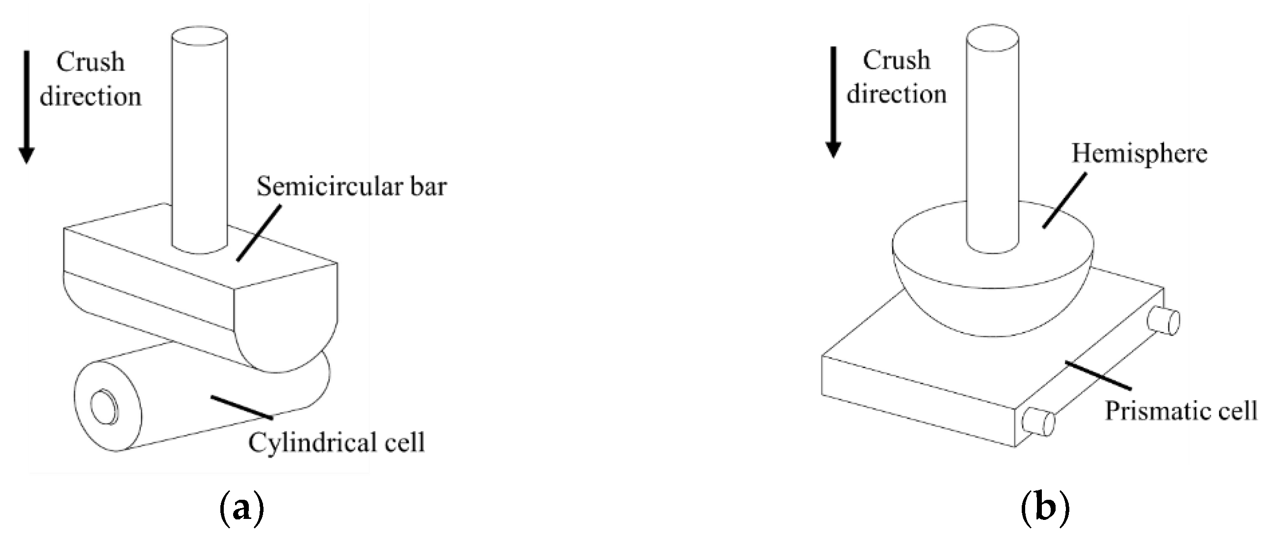
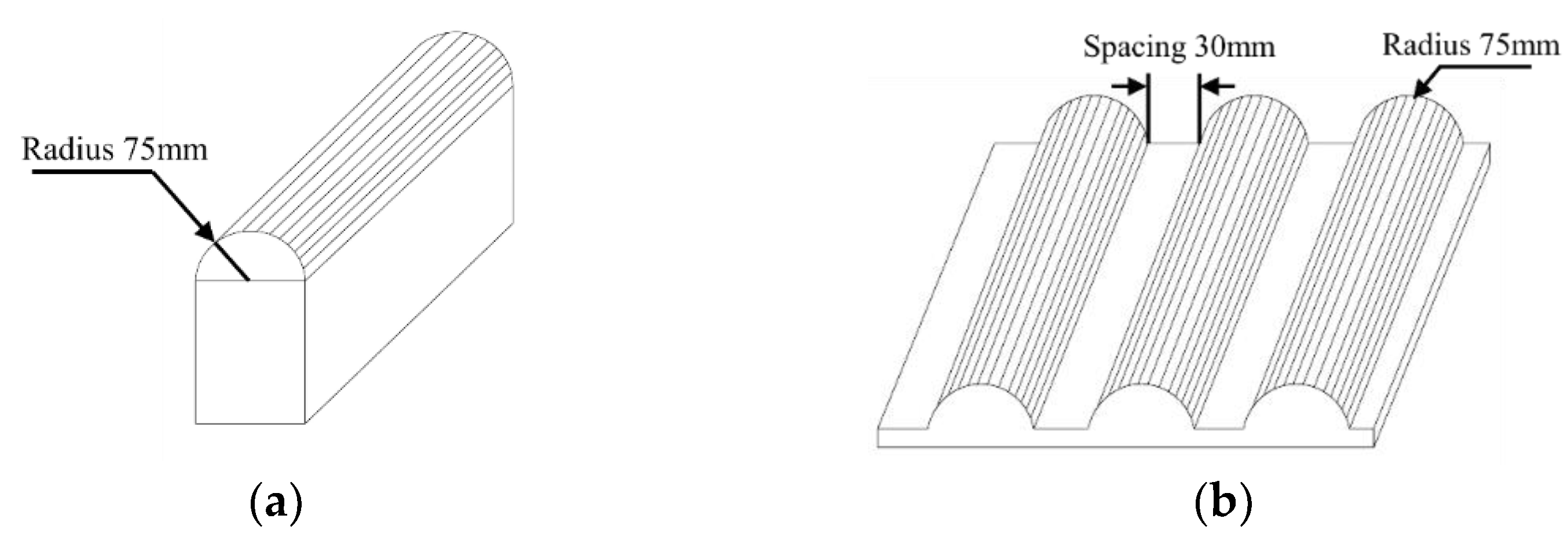
The mechanical shock test simulates the shock to the battery that may occur during a vehicle crash [88]. The standards for LIBs in EVs specify this test item in detail, while the standard for LIBs for energy storage remains blank. In ISO 12405-1(2)-2012 [63], the test battery is required to discharge to 50% SOC, the impact acceleration is 500 m/s2, and the duration is 6 ms. The test is carried out in 6 directions, 10 times in each test direction [89]. IEC 62660-3-2022 [69] requires BEV battery samples to be tested at 100% SOC, while HEV battery samples are to be tested at 80% SOC. The test requires mechanical shocks in six directions of the sample. In SAE J2464-2021 [72], the test requirements are that the impact acceleration is 25 g, the duration is 15 ms, and there are 3 tests on three axes in both positive and negative directions, totaling 18 times. SAND2005-3123 divides the mechanical shock test into three levels, namely low, mid-1, and mid-2 [75]. The acceleration in the low level is 20 g and the maximum duration is 55 ms; the acceleration in mid-1 is 30 g and the duration is 65 ms; the acceleration in mid-2 is 20 g and the duration is 110 ms [90]. The test method in UL 2580-2020 [77] is consistent with SAE J2464-2021. In GB 38031-2020 [84], the mechanical shock test is conducted on the Z-axis direction of the battery pack or system. The shock acceleration is 7 g with a duration of 6 ms, and the test is performed 6 times in each direction of the Z-axis.

2.2.4. Crush Test

The crush test simulates the external load force that may cause deformation of the battery and verifies the safety performance of the battery [91]. In IEC 62660-3-2022 [69], the tested samples are divided into pure and hybrid EV batteries. The SOC of pure EV batteries needs to be adjusted to 100% and that of hybrid EV batteries to 80%. During the test, the battery flat is placed on an insulated rigid flat surface and pressed with a round or semi-circular rod or ball with a diameter of 150 mm, as shown in Figure 1. The center of the tested battery is crushed with a crushing speed of less than or equal to 6 mm/min. The condition for the termination of the test is that the voltage of the tested battery drops by one-third, the battery deforms by more than 15%, or the applied force reaches 1000 times the weight of the battery. In SAND2005-3123 [75] and SAE J2464-2021 [72], the tested sample is required to be placed on a textured pressure plate, which is shown in Figure 2b. Then, it is crushed by a flat plate. The whole test is divided into two stages. The first stage is displacement control. The crushing displacement is 15% of the height of the sample, and it is maintained for 5 min. The second stage involves the control of the force and displacement. The crushing displacement reaches 50% of the sample height and then it is maintained for 5 min. The crushing force should be limited to a maximum of 1000 times the weight of the sample. The battery test in UL 2580-2020 [77] also uses a textured pressing plate for crushing, but it adds a limitation that the maximum force applied on the tested object should not exceed 100 ± 6 kN. In GB 38031-2020 [84], the cell crush test uses a half cylinder with a radius of 75 mm, as shown in Figure 2a, to crush the cell. The crushing speed is no more than 2 mm/s until the cell voltage reaches 0V, the deformation reaches 15%, or the crushing force reaches 100 kN or 1000 times the weight of the test cell. The battery pack or system test can involve any of the methods displayed in Figure 2. It is required to test the two directions of the tested object (the vehicle running direction and the horizontal direction perpendicular to the running direction). The crushing speed should be no greater than 2 mm/s and test is stopped when the crushing force reaches 100 kN or the crushing deformation reaches 30% of the overall size of the extrusion direction. For the energy storage standards, the test method for GB/T 36276-2018 [83] is basically consistent with that of GB/T 38031-2020 [38,83], and the crushing form is shown in Figure 2a. However, the two standards are different in terms of the crushing speed and degree. GB/T 36276-2018 [83] requires that the crushing speed is 5 ± 1 mm/s, and when the voltage reaches 0 V, the crushing deformation reaches 30%, or the extrusion force reaches 13 ± 0.78 kN, the test shall be stopped. Moreover, the test for the battery module during energy storage should be stopped when the deformation reaches 30% or the crushing force reaches 13 ± 0.78 kN.

2.2.5. Penetration Test

The penetration test is used to test the battery safety by drilling a steel needle into a LIB at a certain speed [92,93]. In SAE J2464-2021 [72] and SAND2005-3123 [75], a 3-mm-diameter steel needle penetrates the single cell with a speed of 8 cm/s until the battery is fully pierced. For battery modules and packs, it is penetrated with a 20-mm-diameter steel needle, which needs to pierce at least 3 cells or the penetration depth needs to reach 100 mm. Although GB 38031-2020 [84] does not require a penetration test for a single cell, the TR propagation test is carried out on the battery pack or system. The TR triggering method of a cell can be selected for steel needles with a diameter of 3–8 mm, whereby the angle range of the needle tip is 20–60° and the needling speed range is 0.1–10 mm/s.

2.2.6. Rollover Test

The rollover test is used to evaluate the battery safety when the vehicle is rotated [59]. In SAE J2464-2021 [72] and SAND2005-3123 [75], it is required to first turn the test battery at 360°/min for one cycle, then turn it around at 90° increments and hold each position for 60 min. In UL 2580-2020 [77], a fully charged battery is flipped at a speed of 90°/15 s, and it needs to be rotated 360° in 3 different directions that are perpendicular to each other.

2.2.7. Impact Test

The impact test is designed to assess the mechanical integrity of the housing and its ability to provide mechanical protection to the contents of the battery system [35]. In IEC 62619-2022 [70], the test requires a cylindrical metal bar to be placed on the sample and dropped on the bar using a 9.1 kg object from a height of 610 ± 25 mm. In UL 1973-2022 [79], however, the test requires a steel ball, measuring 50.8 cm in diameter and 535 g in weight, to be dropped directly onto a fully charged battery from a height of 1.29 m, or a steel ball is suspended by a rope and swung like a pendulum to collide the ball with the test battery, starting at a vertical height of 1.29 m.

2.3. Electrical Tests

The electrical tests can be divided into external short circuit tests, overcharge tests, overdischarge tests, and others. The relevant test characteristic parameters in each standard are listed in Table 5.

2.3.1. Overcharge Test

The overcharge test evaluates the safety performance of a battery or battery system under overcharge conditions [94]. In ISO 12405-1(2)-2012 [63], only the overcharge protection function of the battery system is tested. During the test, the cooling system is turned on. The test sample is required to be fully charged and charged with a constant current of 5 C (2C in ISO 12405-2-2012) until the protection device is activated and the charging is automatically interrupted, the SOC reaches 130%, or the battery temperature exceeds 55 °C (the limits of the SOC and the temperature are determined by the manufacturer). IEC 62660-3-2022 [69] requires the battery to be tested at the initial state of 100% SOC. The battery of the pure EVs is charged at 1 C or 1/3 C, while that of the hybrid EVs is charged at 5 C or 1 C. When the voltage of the tested battery reaches 120% or the SOC reaches 130%, the overcharge is stopped. In SAE J2464-2021 [72], the cell test is overcharged with the maximum current until the cell reaches a maximum voltage of 150% or 200% SOC. However, for the overcharge test of the module the battery pack is charged at the 1 C current, and when the pack voltage is above 400 V, it only needs to be overcharged to 120% of the maximum voltage. In SAND2005-3123 [75], the two tests are differentiated considering the different overcharging scenarios of pure and hybrid EVs. For pure EVs, the test sample is charged with a constant current of 32A and the battery voltage does not exceed 450 V. In hybrid EVs, the recommended charging current is 32A. The upper limit for the power supply voltage should be set so as not to exceed the maximum voltage delivered by EVs. The above test is performed with the passive overcharge protection device running. The charging should continue until the sample fails or reaches 200% SOC. In UL 2580-2020 [77], a fully discharged test sample is overcharged at the maximum specified current until the protected circuit is terminated or the battery under testing is charged to 110% of its rated charging capacity or the limit specified by the manufacturer. In GB 38031-2020 [84], the single cell is charged at a constant current of no less than 1/3 C when it is fully charged until it reaches 1.1 times the charging termination voltage specified by the manufacturer or 115% SOC. The overcharge test of the battery system requires the SOC to be in the middle part of the normal operating range, and the charging strategy with the shortest time permitted by the manufacturer is adopted. Charging shall be stopped when the tested sample stops charging, the temperature of the tested sample exceeds the maximum temperature defined by the manufacturer by 10 °C, or the test sample continues to charge for 12 h. In the standards for energy storage batteries, IEC 62619-2022 [70] requires that sample cells are charged with a constant current equal to the maximum specified charging current of the battery system until the voltage reaches the maximum voltage value that is possible under the condition where the original charging control does not work [95]. In UL 1973-2022 [79], the test battery is overcharged with the maximum charging current specified by the manufacturer to reach 110% of its specified maximum charging voltage limit. GB/T 36276-2018 [83] requires the test battery to be charged at a constant current, and the charging current is 1 C. In the cell test, the charging is stopped when the battery voltage reaches 1.5 times the charge termination voltage or after charging for 1 h. In the module test, the charging is stopped when any cell voltage reaches the above conditions.

2.3.2. Overdischarge Test

The overdischarge test simulates the safety of the battery or battery system under the condition of overdischarge [96,97]. In ISO 12405-1-2012 [63], the battery system is discharged at 1 C until the guard automatically interrupts the discharge or the sample voltage drops to 25% of the nominal voltage or continues to discharge for 30 min. In IEC 62660-3-2022 [69], the test sample with 0% SOC is discharged at 1 C current until the sample voltage reaches 25% nominal voltage or the test lasts for 30 min. SAE J2464-2021 [72] requires that both cells and modules discharge at the maximum current. In the cell test, the cell is discharged from full charge until the discharge capacity is twice the battery capacity. The stop condition of the module overdischarge is that the module voltage reaches 0.0 V ± 0.2 V under load. In Sand2005-3123 [75], the test battery with 100% SOC is discharged at 1 C current for 1.5 h, or until 50% of all subassemblies (for the module- or packet-level tests) have achieved voltage reversal for 15 min. In UL 2580-2020 [77], the test battery is discharged at the specified maximum current from full charge until the guard is activated or an additional 30 min after the discharge limit is reached. GB 38031-2020 [84] requires a fully charged single cell to be discharged at 1 C current for 90 min, but the initial state of the battery system during testing is not specified. When the voltage of the test battery is reduced to 25% of its rated voltage or the temperature change of the test battery is less than 4 °C within 2 h, the test can be finished. In the energy storage battery standards, IEC 63056-2020 [71] requires that the battery system discharge at the maximum specified current starting from 30% SOC. The test should be carried out until the BMS terminates the discharge. IEC 62619-2022 [70] requires the test battery to be discharged at a discharge rate of 1 C for a test period of 90 min. In UL 1973-2022 [79], the test battery is discharged with the maximum discharge current for an additional 30 min after reaching the lower limit of the normal discharge voltage. In GB/T 36276-2018 [83], the discharge current takes the smaller value of 1 C and the maximum continuous discharge current of the test sample. In the single test, the discharge is stopped when the battery continues to discharge for 90 min or the battery voltage reaches 0 V. In the module test, the discharge is stopped when the battery continues to discharge for 90 min or the voltage of any cell reaches 0 V.

2.3.3. External Short Circuit Test

The external short circuit test is used to evaluate the bearing capacity of the battery after the external short circuit [98,99,100]. ISO-12405-1-2011 [46] selects 100 mΩ conductors for the external short circuit and lasts for 10 min, while ISO-12405-2-2012 [64] selects 20 mΩ conductors [101]. IEC 62660-3-2022 [69] and SAND2005-3123 [75] use conductors of less than or equal to 5 mΩ for 10 min to simulate the external short circuit. In SAE J2464-2021 [72], the external short circuit test uses conductors of less than or equal to 5 mΩ and the test time lasts for 60 min. UL 2580-2020 requires a resistance of 20 mΩ to be used for the test until the sample is completely discharged or the test lasts 7 h [77]. GB 38031-2020 [84] requires the external short circuit of the cell to last for 10 min, the conductor should be less than 5 mΩ, and the battery system test selects a conductor of no more than 5 mΩ. The test is stopped when short-circuited for 1 h. IEC 63056-2020 [71] requires that the test selects conductors of (30 ± 10 mΩ) * (number of series/number of parallels) or conductors of less than or equal to 5 mΩ. The test lasts 6 h or stops when the case temperature drops by 80% of the maximum temperature increase. In IEC 62619-2022 [70], each cell is short-circuited by connecting the positive and negative terminals with a total external resistance of 30 mΩ ± 10 mΩ. The cells are to remain under testing for 6 h or until the case temperature declines by 80% of the maximum temperature increase, whichever is sooner. In UL 1973-2022 [79], the total short resistance of the test sample shall be 20 mΩ. The battery should be completely discharged or the test is stopped when temperature on the center module has reached a peak or stable state or a fire or explosion has occurred. The test methods for energy storage batteries and modules in GB/T 36276-2018 [83] are consistent with those for battery cells in GB 38031-2020 [84].

2.3.4. Internal Short Circuit Test

The internal short circuit test simulates the situation where conductive particles cause an internal short circuit in the battery [18,102,103]. In IEC 62660-3-2022 [69], the internal short circuit test can be achieved by inserting nickel particles into the cell. In addition, IEC 62660-3-2022 [69] also proposes an alternative method to simulate the internal short circuit, which is to pierce 1–2 layers of the pole sheet with a nail. SAE J2464-2021 [72] does not require an internal short circuit test but provides some methods to simulate a short circuit, such as inserting nickel particles into the battery or by crushing a blunt nail. In the same way, IEC 62619-2022 [70] also simulates an internal short circuit by inserting nickel particles into cells and then extruding them. This test has the disadvantages of being very difficult, being inconvenient to operate, and having questionable repeatability; thus, it is rarely included in the standards. However, our team is still working on new methods that can better simulate internal short circuit failures in test standards.

2.4. Environmental Tests

The environmental tests include high-temperature endurance, thermal shock, damp heat cycle, and water immersion tests. The relevant test characteristic parameters in each standard are summarized in Table 6.

2.4.1. High-Temperature Endurance Test

The high-temperature endurance test simulates the high-temperature environment that the battery may experience and verifies the battery’s safety [104,105]. The test methods for IEC 62660-3-2022 [69], GB 38031-2020 [84], and GB/T 36276-2018 [83] are the same. All of them put the test sample into a hot box, which is heated to 130 ± 2 °C at a temperature rise rate of 5 K/min and kept for 30 min. In SAE J2464-2021 [72], the test method is to place the sample in a radiation heater for 20 min, in which the heater needs to reach 590 °C within 5 min. However, in IEC 62619-2022 [70], the test requires a hot box temperature of 85 ± 5 °C and the test sample needs to be kept at a high temperature for 3 h.

2.4.2. Thermal Shock Cycle Test

The thermal shock cycle test simulates a situation where the temperature suddenly changes to ensure the battery’s safety against thermal shock. ISO 12405-1-2011 [63] requires that the test battery is first discharged to 50% SOC at 1 C and then thermally cycled from −40 to 85 °C, while the transition between the two extreme temperatures should be completed within 30 min. Each extreme temperature needs to be maintained for 1 h, and the entire test requires 5 cycles. The test method of ISO-12405-2-2012 [64] is basically the same as the above, except that the initial SOC of the test sample is 80%. IEC 62660-3-2022 [69] is performed following IEC 62660-2-2018 [68]; the temperature cycle range is also 40 to 85 °C, and the test requires 30 cycles. In SAE J2464-2021 [72], the test requires the test sample to be performed at the maximum working SOC, with thermal cycling between −40−70 °C, while the conversion between extreme temperatures should be within 15 min. The cell needs to be kept for at least 1 h at an extreme temperature and the module needs to be kept for 6 h, and the above process is cycled 5 times. In SAND2005-3123 [75], the SOC of the test battery must be adjusted to 50%; then, the battery is thermally cycled between −4 and 80 °C, and the conversion between two extreme temperatures should be completed within 30 min. UL 2580-2020 [77] is also implemented following SAE J2464-2021 [72], but the cycle temperature range is −40–85 °C. GB 38031-2020 [84] requires the cell to be cycled between −40 and 85 °C for 5 cycles. The battery system is cycled 5 times from −40 to 60 °C, the extreme temperature conversion is completed within 30 min, and the extreme temperature is maintained for 8 h. This test is not included in the standards for energy storage batteries.

2.4.3. Damp Heat Cycle Test

The damp heat cycle is simulated in a high-temperature and high-humidity environment to ensure the battery’s safety [106]. ISO 12405-1(2)-2012 [63,64] is implemented following IEC 60068-2-30 but specifies a temperature range of 25~80 °C and a relative humidity range of 55~98% for 5 cycles. The temperature range required in GB 38031-2020 [84] is 25~60 °C and the humidity range is 55~98%, with 5 cycles. For the energy storage standard, GB/T 36276-2018 [83] only tests the battery safety under high humidity and high heat, without thermal cycling, which requires the test sample to be kept at a temperature of 45 °C and relative humidity of 93% for 3 days.

2.4.4. Immersion Test

The immersion test simulates a situation where the vehicle or battery system is flooded [18,107]. In SAE J2464-2021 [72], the test sample needs to be fully immersed in a 5% NaCl solution for 2 h. SAND2005-3123 [75] also immerses the test sample in salt water for at least 2 h. UL 2580-2020 [77] also requires the test sample to be immersed in a 5% NaCl solution for only 1 h. In GB 38031-2020 [84], the battery pack or system is immersed in water after the vibration test. There are two test methods: one is to immerse the test sample in 3.5% sodium chloride solution for 2 h; the other is for the test object with a height of less than 850 mm, and its lowest point should be 1000 mm below the water surface. For a test object whose height is greater than or equal to 850 mm, the highest point should be 150 mm lower than the water surface and the test should last for 30 min. In the energy storage standards, UL 1973-2022 [79] requires that the test sample is tested for moisture resistance. It should be subjected to a moisture resistance test based on its IP rating following IEC 60529 or CAN/CSA-C22.2 no. 60529.

2.4.5. Fire Test

The fire test simulates a vehicle under fire conditions to verify whether the battery system will explode [20,108,109]. SAND2005-3123 [75] requires that the test sample at 100% SOC be placed in a cylindrical fixture heated by radiation for 10 min, where the temperature of the heater is 890 °C. In UL 2580-2020 [77], the external fire is conducted on the bottom surface of the test object and the fire source is located in the middle of the test object. During the test, the surface temperature of the shell of the test sample should be monitored. The thermocouple on the enclosure should be placed 25 mm from the bottom. The minimum temperature of at least one thermocouple should be above 590 °C after 5 min of ignition and should be maintained for 20 min before the fire is stopped. In GB 38031-2020 [84], the test is divided into 3 steps. The first step is to ignite the gasoline at least 3 m away from the test sample for 60 s of preheating; the second step is to place the burning oil pan directly under the test sample and burn it directly for 70 s. The third step is to cover the oil pan with a refractory heat insulation board and indirectly burn it for 60 s. Finally, the test sample should be separated from the ignited oil pan and observed for 2 h. For the energy storage standard, UL 1973-2022 [79] also stipulates that the test sample needs to be tested using external fire for 20 min.

2.4.6. Salt Spray Test

The salt spray test simulates the use of vehicles or energy storage systems in coastal areas [110]. UL 2580-2020 [77] is performed following the level 6 test method in IEC 60068-2-52-2017 [111], which requires that the sodium chloride concentration of the sprayed solution collected is 50 ± 5 g/L. The entire test requires eight cycles, and each cycle lasts for 7 days. One cycle shall consist of spraying the specimen with a salt solution at 35 ± 2 °C for 2 h, followed by humid conditions at 40 ± 2 °C and 93% ± 3% RH for 22 h. The above process shall be repeated 4 times. The test specimens shall then be stored under a standard atmosphere at 23 ± 2 °C and 50% ± 5% RH for three days. In GB 38031-2020 [84], the concentration of the sodium chloride in the spray solution is 5 ± 1%, and its pH value range is 6.5–7.2 at 35 °C. The battery is sprayed for 8 h and rested for 16 h. The above process is circulated 6 times at 35 °C. For the energy storage standards, UL 1973-2022 [79] and GB/T 36276-2018 [83] follow the test methods in IEC 60068-2-52-2017 [111]. The difference is that UL 1973-2022 [79] uses grades 1 and 2 for testing, while GB/T 36276-2018 [83] uses grade 6 for testing.

2.4.7. Low-Pressure Test

The low-pressure test is used to simulate the situation of a vehicle driving at a high altitude [112,113,114]. Due to the geographical diversity of China, this test is only included in the Chinese standards. In GB 38031-2020 [84], the battery pack or system is placed in an environment with an air pressure of 61.2 kPa for 5 h (simulating the air pressure condition at an altitude of 4000 m), then the test sample is discharged at a discharge current of no less than 1/3 C. For the energy storage system standard, GB/T 36276-2018 [83] only requires cells to be tested, whereby the single cells need to stand for 6 h in an environment of 11.6 kPa and 25 °C during the test.

2.5. Thermal Runaway Propagation Test

The thermal runaway propagation test for LIBs is mainly for the battery module or pack [115]. There are few thermal safety tests for battery packs or systems due to the high test costs and complex test procedures. In UL 2580-2020 [77], the TR of the cell can be triggered by acupuncture, overcharge, heating, or other factors. The test requires there to be no external fire propagating from the sample or explosion of the sample within a specific time. SAE J2464-2021 [72] requires repeated testing at different locations. In GB 38031-2020 [84], it is specified that the battery pack or system needs to undergo a thermal propagation test. It is required that the battery pack or system should provide a thermal alarm signal 5 min before the start of thermal propagation caused by the TR of a single cell. The thermal alarm signal may be triggered by the temperature, temperature rise rate, SOC, voltage, current signals, and other abnormal parameters. During the test, the SOC of the test battery is adjusted to no less than 90–95% and placed in an environment above 0 °C, with a relative humidity range of 10%–90% and air pressure range of 86–106 kPa. GB 38031-2020 [84] provides specific test methods for triggering TR by needling or heating. The external heating method uses a surface covered with ceramic, metal, a flat insulation layer, or a rod heating device. The specific requirements are as follows: (1) When the size of the block heating device is the same as that of the battery cell, the heating device can be used to replace one battery cell in the module and can directly contact the battery surface. (2) The heating area of the heating device shall not be greater than the surface area of the battery cell. (3) The test shall be started within 24 h after the heater’s installation, and the battery shall be heated with the maximum power of the heater. Moreover, the temperature sensor is placed on the side away from the heat conduction; that is, on the opposite side of the heater. The recommended needling method uses a steel needle with a diameter range of 3–8 mm and a conical angle range of 20–60° to pierce the cell vertically at a speed range of 0.1–10 mm/s.
For the energy storage standards, IEC 62619-2022 [70], UL 1973-2022 [79], UL 9540A-2019 [78], and GB/T 36276-2018 [83] require a TR propagation test for the battery system. In IEC 62619-2022 [70] and UL 1973-2022 [79], the requirement for test compliance is that the test sample should not ignite or explode. UL 9540A-2019 [78] details the TR test and tests for TR gassing. GB/T 36276-2018 [83] requires that there should be no fire, no explosion, and no TR propagation after the TR of the single cell. In the actual operation of the energy storage system, electrical abuse and thermal abuse are more likely to occur. Therefore, two recommended TR triggering methods are given in the standard, and the cell in the center of the battery module should be triggered during the test. The overcharge trigger for the TR is to charge the cell at a constant current with a maximum current greater than or equal to 1/3 C and less than or equal to the maximum working current until the charged cell reaches TR or its SOC reaches 200%. Moreover, only the triggered battery cell shall be overcharged, and other cells in the battery module shall not be overcharged. The other heating trigger method is the same as the heating method given in GB 38031-2020 [84].
From the above analysis, it can be seen that most of the test methods for TR propagation are designed to trigger the TR of a cell in the battery system using certain triggering methods. The common triggering methods are needling, heating, and overcharge, as shown in Figure 3. Almost all standards do not stipulate that only one method can be used for the TR test, because there are many reasons for battery TR. However, some TR trigger methods are recommended in some standards, such as needling and heating are recommended in GB 38031, GB/T 36276, and GB 38031 for EV batteries, and the heating power is closely related to the battery capacity. GB/T 36276 recommends overcharge triggering for energy storage batteries. Generally, the trigger method most likely to cause TR should be selected based on the application scenarios. There are a few standards related to the TR propagation test for the LIB in EVs, and there is no requirement for no TR propagation. Most of the standards of energy storage batteries require a TR propagation test. However, the evaluation criteria are inconsistent. A TR propagation test in China needs to meet the requirement of having no TR propagation, which is relatively strict. The test requirements in other countries are lower, only requiring that the battery not ignite or explode.

3. Case Analysis of Battery Fire

Although the various standards on LIBs are constantly updated, iterated, and improved, the safety of LIBs is far from the ideal state. Fire accidents involving LIBs used for EVs and energy storage frequently occur [116,117], which bring about huge losses and attract public concern.

3.1. Fire Accidents Involving EVs

With the increase in EVs, fire accidents are also increasing. According to our incomplete statistics, 22 and 45 fire accidents involving EVs were reported in 2017 and 2018, respectively, in China [118], and the number reached 138 in 2021, as shown in Figure 4a. This has attracted the attention of society to the safety of EVs.
Figure 4b shows the investigation results for EV fire accidents in China in 2021. The fire accidents involving EVs will increase with the warming of the weather. The probability of EV fire accidents is greatest in summer and gradually decreases in winter. In addition, it is reported that most fire incidents occurred in the south of China, such as Hangzhou, Guangzhou, Shenzhen, and other places. The main reason may be related to the large number and high penetration of EVs in the south, where high-temperature weather is more likely.
Figure 4c shows the on-site photos of some EV fire accidents. It can be observed that some EVs suddenly generate smoke and fire while driving, some occur in the process of charging, and some are caused by vehicle collisions. To better analyze the fire accidents involving EVs, the fire accidents from 2018 to 2021 are classified and counted in Figure 4d. Fire accidents involving EVs usually occur in three states, including charging, parking, and driving. In 2021, fire accidents during charging accounted for approximately 27.16%, fire accidents during parking accounted for approximately 33.33%, fire accidents during driving accounted for approximately 27.16%, fire accidents caused by collisions accounted for approximately 7.41%, and fire accidents under other conditions accounted for approximately 4.94% of the total. The proportion of vehicle fire accidents caused by mechanical abuse, such as collisions, is not high, while the probability of accidents during charging, parking, and driving is as high as 87.65%. The main cause of TR in EV batteries is probably electricity abuse, and it is more likely that an internal short circuit may be caused by the battery aging and the lithium plating [119,120,121]. In the statistics for EV fire accidents, almost no vehicles can be rescued and extinguished in time, and almost all vehicles are completely burned. Meanwhile, the surrounding vehicles and buildings will also be involved, causing huge losses. When TR occurs in a battery, the chemical substances inside the battery will decompose rapidly and release a large amount of heat. However, CO2, dry powder, and other fire extinguishing agents cannot prevent the violent chain decomposition reactions inside the battery [122,123]; therefore, the fire accidents involving EVs always burn violently and are prone to reigniting. From the accident statistics, it can be found that many vehicles catch fire during charging and parking. Fortunately, at this time there is usually no one around the vehicle, although this means it is impossible to report to the police and inform the firefighters in time, thereby causing the surrounding vehicles and buildings to be burned.
The main process of fire accidents involving EVs is shown in Figure 5. In the early stage, the battery usually emits white smoke first, which becomes more and more intensive. Many people have actively used fire extinguishers to put out fires to reduce the disasters caused by accidents, but the positive effects have been minimal. It is not until the firefighters come to the scene and use high-pressure water guns to spray water on the train to cool down the fire that the fire is effectively suppressed. However, after the open fire is extinguished, the vehicles will reignite, which causes great difficulties for firefighting. Some experienced firefighters will overturn the vehicle, use bag-breaking tools to break the shell of the battery pack, and then spray cooling water directly into the battery pack for cooling. This method is very effective in dealing with fire accidents involving EVs.

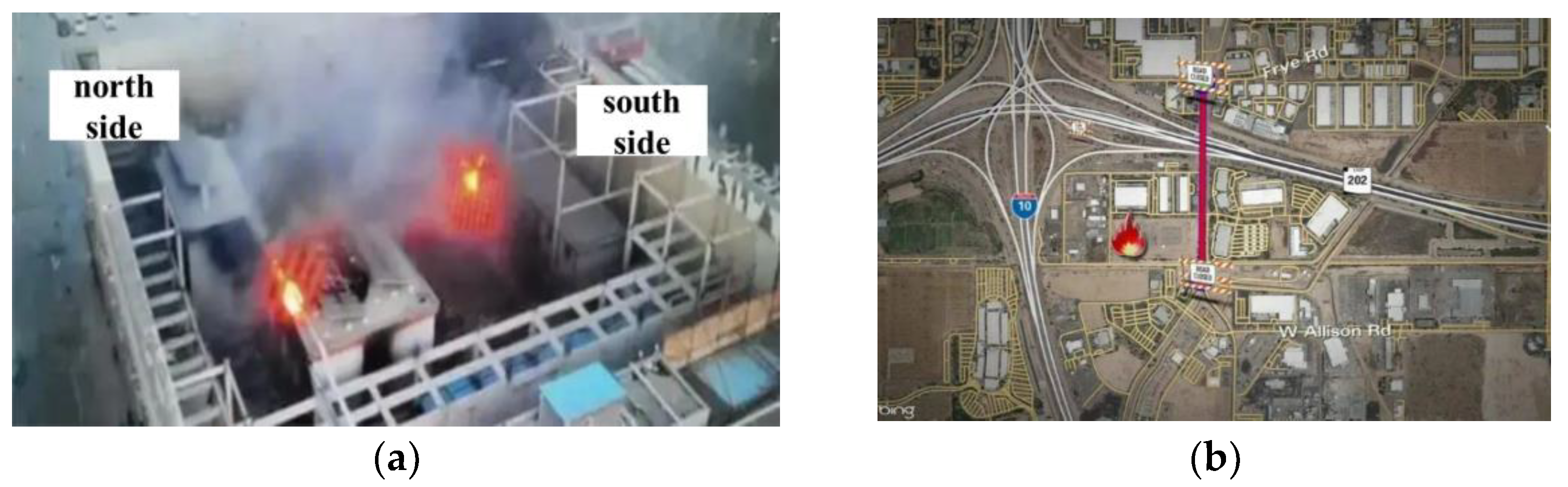
3.2. Fire Accidents from Energy Storage Power Stations

With the large-scale application of LIBs in energy storage power stations, their fire safety has attracted more and more attention. In recent years, fire accidents in energy storage power stations have occurred gradually. The fire accident losses in an energy storage power station are far greater than in EVs. According to the incomplete statistics, the accidents in energy storage power stations in the last 10 years are listed in Table 7.
Table 6 shows that the installed capacity of LIBs in energy storage power stations has been increasing in recent years, and fire accidents are gradually increasing. For energy storage, lithium iron phosphate (LFP) batteries are mainly used in China, while batteries with ternary cathodes are adopted in other countries. For these energy storage accidents, less information is publicly reported. Among them, China released an investigation report on a fire and explosion accident in an electrical energy storage power station in Beijing. According to the report, the direct cause of the fire in the south building was an internal short circuit fault of the LFP battery, which caused the battery TR. The direct cause of the explosion in the north building was that the combustible and explosive components generated in the south building entered the energy storage room in the north building through the underground cable trench and mixed with the air to form explosive gas, which exploded in the presence of electric sparks, as shown in Figure 6a. Figure 6b shows a schematic diagram of the fire accident in an energy storage power station in Arizona in the United States on April 18, 2022. There were more than 3200 cells in the energy storage project, with a total energy storage capacity of 40 MWh. After the fire accident occurred, the power station burned for 5 days, and thick smoke was emitted continuously, which not only caused huge losses but also seriously affected the surrounding environment. The losses caused by a fire accident in an energy storage power station often equal tens of millions dollars, producing a lot of environmental pollution. Moreover, once a fire accident occurs in an energy storage power station, the difficulty of the fire rescue is far greater than for EVs. Firefighters often need several days to put out the fire, and the workforce and material resources consumed are huge.
Most energy storage power stations store their batteries in containers that are placed in the open air. Some of them store their batteries by placing them in energy storage cabinets in the buildings. Different building forms have different effects on energy storage accidents. Once a fire accident occurs in a building, the toxic, combustible, and explosive gases released by the failed battery easily accumulate in the house, which may aggravate the hazard of the fire accident and increase the difficulty of extinguishing the fire. Energy storage power station with open-air containers are more susceptible to the influence of weather and other environmental factors, which increases the accident rate. Although there are many factors that lead to energy storage safety accidents, such as the battery management systems, cable harnesses, the operating environment, safety management, and other factors, the primary cause is the battery itself. When a fire accident occurs, the energy storage power station is normally in operation. During the charging and discharging process of LIBs, the thermal safety of the battery may be affected due to its own defects, the lithium plating, aging, an internal short circuit, and other reasons, and then the safety may be affected. The huge number of batteries has also caused a great test burden for the battery management systems, given the inconsistency between batteries. Some retired batteries from EVs are used for energy storage [124,125,126], significantly increasing the safety risk to the energy storage power station.

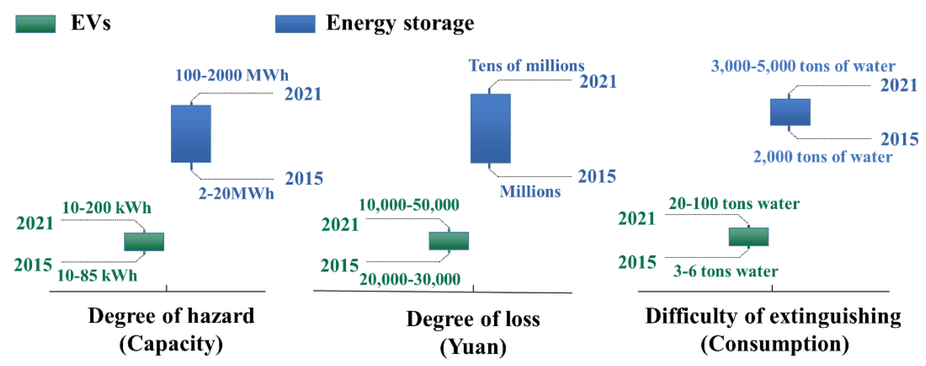
3.3. Comparison and Analysis

From the above analysis, the fire accidents in EVs and energy storage power stations are generally caused by the TR of LIBs. In the early stage of a fire accident, white smoke will be emitted and then ignited. The rapid spread of the fire leads to the TR of the surrounding batteries, and a large amount of thick smoke is continuously emitted, accompanied by an explosion. Upon the arrival of firefighters, a large amount of cooling water spray is usually used to extinguish and cool the fire, meaning the fire can be controlled. The difference is that EVs that are on fire can be completely burned in a few minutes. The large number of batteries in an energy storage power station provides sufficient energy for flame combustion. The whole fire often lasts for dozens of hours and even several days for large energy storage power stations. Figure 7 compares the difference between EVs and energy storage power stations in terms of the hazard, firefighting difficulty, and loss of fire accidents. At present, the safety problem for energy storage batteries is more prominent for EV batteries. The fire water required for a single EV may equal 100 t, while the fire water required for a large energy storage power station may be as high as 5000 t, and spraying this water for cooling often takes several days. The losses caused by fire accidents increase as the battery energy storage system expands. The loss of a single EV can cost tens of thousands of dollars, while the loss of an energy storage power stations is in the millions. Therefore, battery safety in energy storage power stations needs to be further emphasized, bottleneck technology needs to be advanced, and the test standards need to be developed and strengthened.

4. Prospects and Suggestions

The use of standards is the highest priority for guaranteeing battery safety, and the products produced according to such standards are regarded as qualified. The safety standards play a vital role in improving the safety of LIBs and their systems. However, there are still some shortcomings in the current safety standards. Based on our investigation and analysis of fire accidents, we put forward four suggestions for updating the relevant standards to improve battery safety and reduce the probability of fire accidents.
(a)
Design early warning and cloud alarms for battery TR: There is a high probability of fire accidents in the charging process and the static process after charging. At this time, the battery system is usually in a high SOC state and has a relatively high temperature. It is necessary to strengthen the early detection and warning of potential TR causes. At the same time, it is also necessary to monitor the temperature and gas state in the critical positions in the battery system to provide accurate alarms for TR ine single cells [127,128,129], which can remind people to evacuate and dial the fire alarm telephone number in time. Currently, most of the relevant battery safety standards regulate the abuse of the battery itself. There are few safety management standards for battery systems, and there is a lack of standards for TR warnings and fire cloud alarms. Therefore, developing these standards will be an important task in the future.
(b)
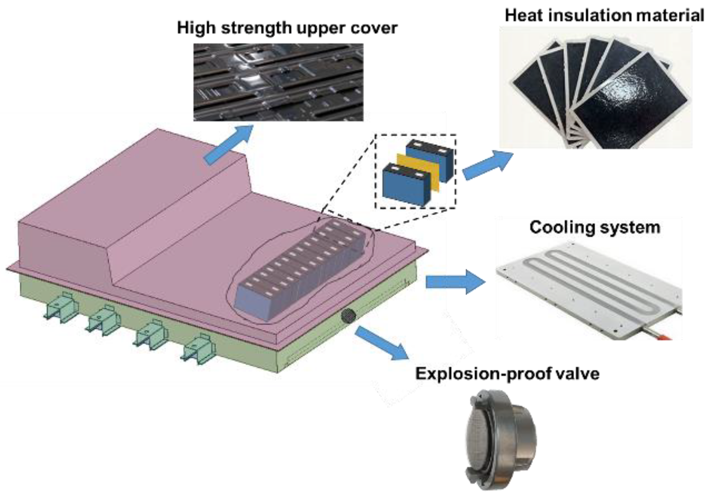
Innovative structural design for no-fire battery packs: Effectively delaying the TR propagation of LIBs will result in longer rescue times. In many cases, when the TR of a single cell occurs, the high-temperature particles can burn through the shell of the battery pack, meaning the oxygen and the combustible electrolyte gas generated by the battery failure are fully mixed and burnt. An effective means is to strengthen the structural design of the battery pack [91,130]. Figure 8 shows the structure design of a no-fire battery pack. This strengthens the heat insulation and dissipation function of the battery pack through the reasonable design of the fire shield, heat insulation sheet, cooling system, and explosion-proof valve to delay the TR propagation and prevent the battery pack shell from burning through. Moreover, the arc generated by the high-voltage system upon thermal failure will destroy the preset protection countermeasures against TR propagation. Therefore, the arc issues should be more emphasized in future standards. In addition, most standards only take the non-fire and non-explosion scenarios of the whole battery pack as the evaluation requirements, lacking a strength test for the battery pack shell. It is necessary to restrict and regulate the structure and fire resistance of the battery pack in the standards.
(c)
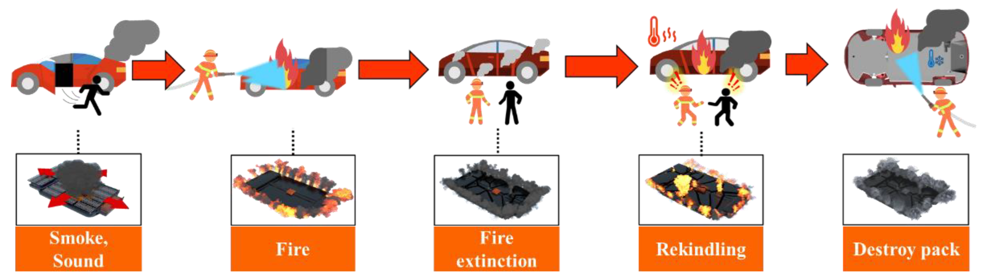
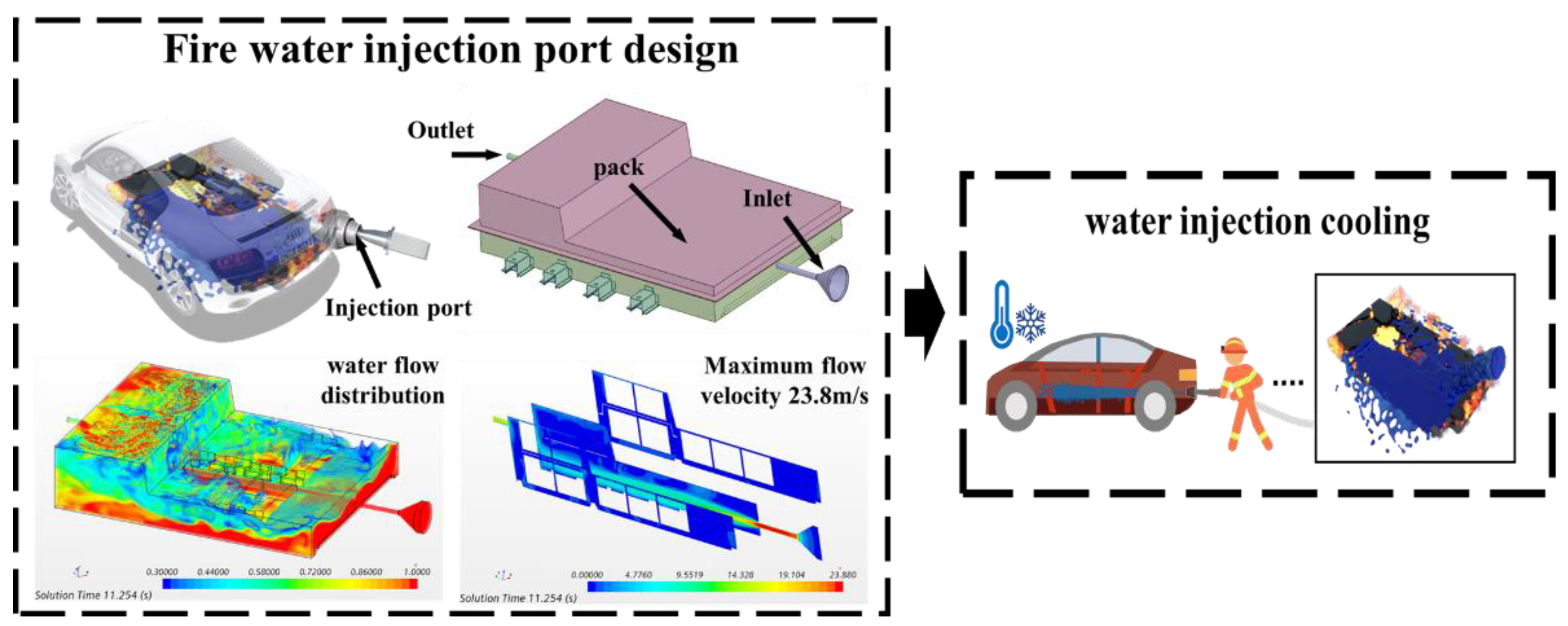
Design a fire water injection interface for the battery pack: The battery pack is located at the bottom of the vehicle and has a certain waterproof design. It is difficult to reach a battery undergoing TR inside the battery pack through conventional external spraying measures, which increases the difficulty for firefighters to extinguish the fire. In the actual firefighting process, experienced firefighters may overturn the vehicle to break the package and then spray water into the battery pack to cool it down. Therefore, it is necessary to improve the structure of the battery pack and even the vehicle body. As shown in Figure 9, the design idea for a fire interface that can be connected to a fire water gun is provided. After the open fire is extinguished, the fire hydrant can be directly connected to the firefighting interface to cool the inside of the battery pack. At the same time, the process of spraying water into the battery pack can be simulated through the model to design the optimal battery pack structure. At present, there are few fire safety standards for EVs, and it is difficult to guide the firefighting process. Installing a fire interface on the battery pack could effectively reduce the temperature and extinguish the fire, which is an effective way to deal with EV fire accidents.
(d)
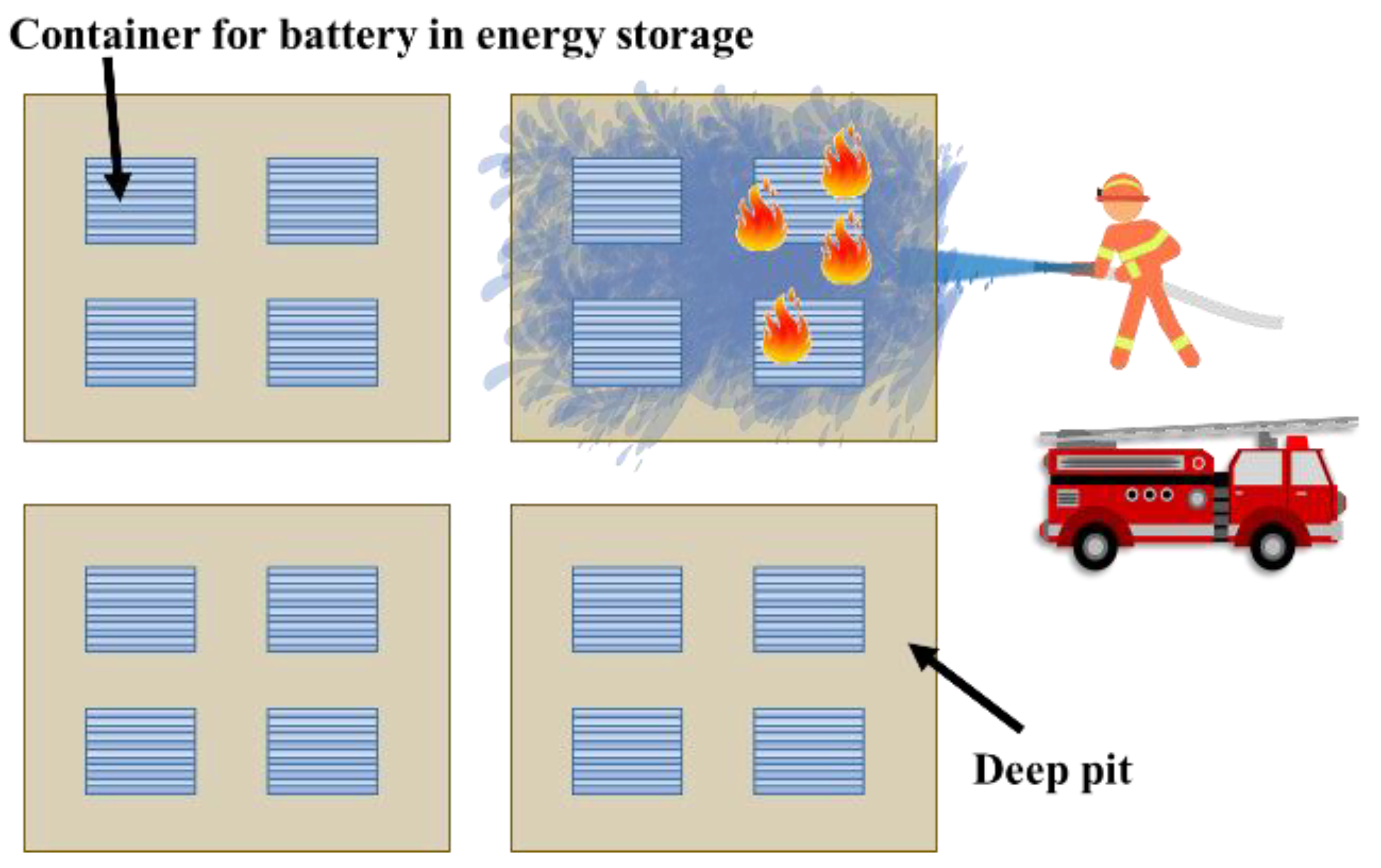
Design immersive energy storage power stations. According to the existing fire accidents involving energy storage power stations, it can be found that once a fire accident occurs, the current fire extinguishing measures may not be effective. The whole process of firefighting consumes a large amount of cooling water. Moreover, the cooling water ejected by the firefighters cannot fully act on the TR batteries, resulting in a large amount of water loss, which is a waste of water resources. Therefore, it is necessary to improve the fire protection measures for energy storage power stations. As shown in Figure 10, an immersive energy storage firefighting design is provided, in which the storage container is placed in deep pits or low-lying areas. In case of fire, the firefighters can directly inject cooling water into the deep pit to immerse the containers to reduce the temperature and greatly save water resources. In addition, the containers can be grouped into pits. When a container catches fire, water is poured into the pit, which not only improves the fire extinguishing efficiency but also reduces the impact on other containers, thereby reducing the accident losses.

5. Conclusions

The thermal safety of LIBs is a hot but complex topic for battery research, development, and application. Improving the safety of LIBs is very important for their sustainable development. The safety standards play a critical role in promoting the safety of LIBs. The standards should be constantly revised and evolved with the development of LIBs. This paper summarizes the global safety standards for LIBs for vehicles and energy storage systems and analyzes the technical characteristics and applications. In addition, the fire accidents involving EVs in 2018–2021 and the fire accidents involving energy storage power stations in the past 10 years are assessed, after which the main characteristics of the failure accidents are compared and analyzed, providing a valuable reference for the development of relevant safety standards. Finally, four suggestions and prospects for upgrading the safety standards are put forward: (1) developing early warning and cloud alarm technologies; (2) designing no-fire battery packs; (3) designing fire extinguishing water injection interfaces for the battery packs; (4) designing immersive fire extinguishing methods for energy storage batteries. Promoting the safety of LIBs requires the joint efforts of the government, research institutes, and industry. Our research has significant reference value for promoting the formulation of relevant safety standards for LIBs.

Author Contributions

Conceptualization, X.L., J.Y., C.J., X.F., H.W., C.X. and Y.Z.; methodology, J.Y., C.J. and X.F.; validation, X.L. and X.F.; investigation, J.Y., C.J., H.W., C.X. and Y.Z.; resources, X.L. and X.F.; data curation, C.J., H.W., C.X. and Y.Z.; writing—original draft preparation, J.Y. and C.J.; writing—review and editing, X.L., J.Y., C.J. and X.F.; supervision, X.F., H.W., C.X. and Y.Z.; funding acquisition, X.L. All authors have read and agreed to the published version of the manuscript.

Funding

This research was funded by the National Natural Science Foundation of China (52076121, 51977131, and 552277223) and the Natural Science Foundation of Shanghai (19ZR1435800).

Institutional Review Board Statement

Not applicable.

Informed Consent Statement

Not applicable.

Data Availability Statement

Not applicable.

Conflicts of Interest

The authors declare no conflict of interest.

References

  1. De La Peña, L.; Guo, R.; Cao, X.; Ni, X.; Zhang, W. Accelerating the energy transition to achieve carbon neutrality. Resour. Conserv. Recycl. 2022, 177, 105957. [Google Scholar] [CrossRef]
  2. Lai, X.; Chen, Q.; Tang, X.; Zhou, Y.; Gao, F.; Guo, Y.; Bhagat, R.; Zheng, Y. Critical review of life cycle assessment of lithium-ion batteries for electric vehicles: A lifespan perspective. eTransportation 2022, 12, 100169. [Google Scholar] [CrossRef]
  3. Viswanathan, V.; Epstein, A.H.; Chiang, Y.-M.; Takeuchi, E.; Bradley, M.; Langford, J.; Winter, M. The challenges and opportunities of battery-powered flight. Nature 2022, 601, 519–525. [Google Scholar] [CrossRef]
  4. Lebrouhi, B.; Khattari, Y.; Lamrani, B.; Maaroufi, M.; Zeraouli, Y.; Kousksou, T. Key challenges for a large-scale development of battery electric vehicles: A comprehensive review. J. Energy Storage 2021, 44, 103273. [Google Scholar] [CrossRef]
  5. He, H.; Sun, F.; Wang, Z.; Lin, C.; Zhang, C.; Xiong, R.; Deng, J.; Zhu, X.; Xie, P.; Zhang, S. China’s Battery Electric Vehicles Lead the World: Achievements in Technology System Architecture and Technological Breakthroughs. Green Energy Intell. Transp. 2022, 1, 100020. [Google Scholar] [CrossRef]
  6. Liu, J.; Wang, Z.; Hou, Y.; Qu, C.; Hong, J.; Lin, N. Data-driven energy management and velocity prediction for four-wheel-independent-driving electric vehicles. eTransportation 2021, 9, 100119. [Google Scholar] [CrossRef]
  7. Hua, Y.; Zhou, S.; Huang, Y.; Liu, X.; Ling, H.; Zhou, X.; Zhang, C.; Yang, S. Sustainable value chain of retired lithium-ion batteries for electric vehicles. J. Power Sources 2020, 478, 228753. [Google Scholar] [CrossRef]
  8. Liao, Z.; Zhang, S.; Li, K.; Zhang, G.; Habetler, T.G. A survey of methods for monitoring and detecting thermal runaway of lithium-ion batteries. J. Power Sources 2019, 436, 226879. [Google Scholar] [CrossRef]
  9. Wang, C.; Yang, C.; Zheng, Z. Toward Practical High-Energy and High-Power Lithium Battery Anodes: Present and Future. Adv. Sci. 2022, 9, 2105213. [Google Scholar] [CrossRef]
  10. Cappiello, F.L.; Cimmino, L.; Napolitano, M.; Vicidomini, M. Thermoeconomic Analysis of Biomethane Production Plants: A Dynamic Approach. Sustainability 2022, 14, 5744. [Google Scholar] [CrossRef]
  11. Dunn, B.; Kamath, H.; Tarascon, J.-M. Electrical energy storage for the grid: A battery of choices. Science 2011, 334, 928–935. [Google Scholar] [CrossRef] [Green Version]
  12. Wang, H.; Shi, W.; Hu, F.; Wang, Y.; Hu, X.; Li, H. Over-heating triggered thermal runaway behavior for lithium-ion battery with high nickel content in positive electrode. Energy 2021, 224, 120072. [Google Scholar] [CrossRef]
  13. Sun, H.; Zhu, G.; Zhu, Y.; Lin, M.C.; Chen, H.; Li, Y.Y.; Hung, W.H.; Zhou, B.; Wang, X.; Bai, Y. High-safety and high-energy-density lithium metal batteries in a novel ionic-liquid electrolyte. Adv. Mater. 2020, 32, 2001741. [Google Scholar] [CrossRef]
  14. Zhang, H.; Zhang, J. An overview of modification strategies to improve LiNi0· 8Co0· 1Mn0· 1O2 (NCM811) cathode performance for automotive lithium-ion batteries. ETransportation 2021, 7, 100105. [Google Scholar] [CrossRef]
  15. Kremer, L.S.; Hoffmann, A.; Danner, T.; Hein, S.; Prifling, B.; Westhoff, D.; Dreer, C.; Latz, A.; Schmidt, V.; Wohlfahrt-Mehrens, M. Manufacturing process for improved ultra-thick cathodes in high-energy lithium-ion batteries. Energy Technol. 2020, 8, 1900167. [Google Scholar] [CrossRef]
  16. Foreman, E.; Zakri, W.; Hossein Sanatimoghaddam, M.; Modjtahedi, A.; Pathak, S.; Kashkooli, A.G.; Garafolo, N.G.; Farhad, S. A review of inactive materials and components of flexible lithium-ion batteries. Adv. Sustain. Syst. 2017, 1, 1700061. [Google Scholar] [CrossRef]
  17. Gao, Y.; Yin, J.; Xu, X.; Cheng, Y. Pseudocapacitive storage in cathode materials of aqueous zinc ion batteries toward high power and energy density. J. Mater. Chem. A 2022, 10, 9773–9787. [Google Scholar] [CrossRef]
  18. Hu, G.; Huang, P.; Bai, Z.; Wang, Q.; Qi, K. Comprehensively analysis the failure evolution and safety evaluation of automotive lithium ion battery. ETransportation 2021, 10, 100140. [Google Scholar] [CrossRef]
  19. Wang, X.; Wei, X.; Zhu, J.; Dai, H.; Zheng, Y.; Xu, X.; Chen, Q. A review of modeling, acquisition, and application of lithium-ion battery impedance for onboard battery management. ETransportation 2021, 7, 100093. [Google Scholar] [CrossRef]
  20. Sun, P.; Bisschop, R.; Niu, H.; Huang, X. A review of battery fires in electric vehicles. Fire Technol. 2020, 56, 1361–1410. [Google Scholar] [CrossRef]
  21. Liu, P.; Liu, C.; Yang, K.; Zhang, M.; Gao, F.; Mao, B.; Li, H.; Duan, Q.; Wang, Q. Thermal runaway and fire behaviors of lithium iron phosphate battery induced by over heating. J. Energy Storage 2020, 31, 101714. [Google Scholar] [CrossRef]
  22. Larcher, D.; Tarascon, J.-M. Towards greener and more sustainable batteries for electrical energy storage. Nat. Chem. 2015, 7, 19–29. [Google Scholar] [CrossRef]
  23. Zhang, Z.; Ding, T.; Zhou, Q.; Sun, Y.; Qu, M.; Zeng, Z.; Ju, Y.; Li, L.; Wang, K.; Chi, F. A review of technologies and applications on versatile energy storage systems. Renew. Sustain. Energy Rev. 2021, 148, 111263. [Google Scholar] [CrossRef]
  24. Qin, P.; Sun, J.; Yang, X.; Wang, Q. Battery thermal management system based on the forced-air convection: A review. ETransportation 2021, 7, 100097. [Google Scholar] [CrossRef]
  25. Chen, S.; Gao, Z.; Sun, T. Safety challenges and safety measures of Li-ion batteries. Energy Sci. Eng. 2021, 9, 1647–1672. [Google Scholar] [CrossRef]
  26. Zhang, X.; Li, Z.; Luo, L.; Fan, Y.; Du, Z. A review on thermal management of lithium-ion batteries for electric vehicles. Energy 2022, 238, 121652. [Google Scholar] [CrossRef]
  27. Kang, H.; Jung, S.; Lee, M.; Hong, T. How to better share energy towards a carbon-neutral city? A review on application strategies of battery energy storage system in city. Renew. Sustain. Energy Rev. 2022, 157, 112113. [Google Scholar] [CrossRef]
  28. Huo, Y.; Rao, Z.; Liu, X.; Zhao, J. Investigation of power battery thermal management by using mini-channel cold plate. Energy Convers. Manag. 2015, 89, 387–395. [Google Scholar] [CrossRef]
  29. Qiu, Y.; Jiang, F. A review on passive and active strategies of enhancing the safety of lithium-ion batteries. Int. J. Heat Mass Transf. 2022, 184, 122288. [Google Scholar] [CrossRef]
  30. Yu, X.; Chen, R.; Gan, L.; Li, H.; Chen, L. Battery Safety: From Lithium-Ion to Solid-State Batteries. Engineering 2022. [Google Scholar] [CrossRef]
  31. Sun, Z.; Guo, Y.; Zhang, C.; Xu, H.; Zhou, Q.; Wang, C. A Novel Hybrid Battery Thermal Management System for Prevention of Thermal Runaway Propagation. IEEE Trans. Transp. Electrif. 2022, 207, 118198. [Google Scholar] [CrossRef]
  32. Zhou, Z.; Zhou, X.; Li, M.; Cao, B.; Liew, K.; Yang, L. Experimentally exploring prevention of thermal runaway propagation of large-format prismatic lithium-ion battery module. Appl. Energy 2022, 327, 120119. [Google Scholar] [CrossRef]
  33. Feng, X.; Ouyang, M.; Liu, X.; Lu, L.; Xia, Y.; He, X. Thermal runaway mechanism of lithium ion battery for electric vehicles: A review. Energy Storage Mater. 2018, 10, 246–267. [Google Scholar] [CrossRef]
  34. Snyder, M.; Theis, A. Understanding and managing hazards of l ithium-ion battery systems. Process Saf. Prog. 2022, 41, 440–448. [Google Scholar] [CrossRef]
  35. Chen, Y.; Kang, Y.; Zhao, Y.; Wang, L.; Liu, J.; Li, Y.; Liang, Z.; He, X.; Li, X.; Tavajohi, N. A review of lithium-ion battery safety concerns: The issues, strategies, and testing standards. J. Energy Chem. 2021, 59, 83–99. [Google Scholar] [CrossRef]
  36. Kotak, B.; Kotak, Y.; Brade, K.; Kubjatko, T.; Schweiger, H.-G. Battery crush test procedures in standards and regulation: Need for augmentation and harmonisation. Batteries 2021, 7, 63. [Google Scholar] [CrossRef]
  37. Gabbar, H.A.; Othman, A.M.; Abdussami, M.R. Review of battery management systems (BMS) development and industrial standards. Technologies 2021, 9, 28. [Google Scholar] [CrossRef]
  38. Zhenkai, H.; Bo, L.; Yongqi, L.; Youjie, S.; Qikai, L.; Zhipeng, H. Comparative study on safety test and evaluation methods of lithium-ion batteries for energy storage. Energy Storage Sci. Technol. 2022, 11, 1650. [Google Scholar]
  39. Yuan, W.; Liang, D.; Chu, Y.; Wang, Q. Aging effect delays overcharge-induced thermal runaway of lithium-ion batteries. J. Loss Prev. Process Ind. 2022, 79, 104830. [Google Scholar] [CrossRef]
  40. Ke, Q.; Li, X.; Guo, J.; Cao, W.; Wang, Y.; Jiang, F. The retarding effect of liquid-cooling thermal management on thermal runaway propagation in lithium-ion batteries. J. Energy Storage 2022, 48, 104063. [Google Scholar] [CrossRef]
  41. Hu, J.; Liu, T.; Wang, X.; Wang, Z.; Wu, L. Investigation on thermal runaway of 18,650 lithium ion battery under thermal abuse coupled with charging. J. Energy Storage 2022, 51, 104482. [Google Scholar] [CrossRef]
  42. Li, T.; Jiao, Y. Revealing the Thermal Runaway Behavior of Lithium Iron Phosphate Power Batteries at Different States of Charge and Operating Environment. Int. J. Electrochem. Sci. 2022, 17, 2. [Google Scholar] [CrossRef]
  43. Mele, M.L.; Bracciale, M.P.; Ubaldi, S.; Santarelli, M.L.; Mazzaro, M.; Di Bari, C.; Russo, P. Thermal Abuse Tests on 18650 Li-Ion Cells Using a Cone Calorimeter and Cell Residues Analysis. Energies 2022, 15, 2628. [Google Scholar] [CrossRef]
  44. Yin, H.; Ma, S.; Li, H.; Wen, G.; Santhanagopalan, S.; Zhang, C. Modeling strategy for progressive failure prediction in lithium-ion batteries under mechanical abuse. ETransportation 2021, 7, 100098. [Google Scholar] [CrossRef]
  45. Li, H.; Wang, H.; Xu, Z.; Wang, K.; Ge, M.; Gan, L.; Zhang, Y.; Tang, Y.; Chen, S. Thermal-responsive and fire-resistant materials for high-safety lithium-ion batteries. Small 2021, 17, 2103679. [Google Scholar] [CrossRef]
  46. Jiang, Z.; Qu, Z.; Zhang, J.; Rao, Z. Rapid prediction method for thermal runaway propagation in battery pack based on lumped thermal resistance network and electric circuit analogy. Appl. Energy 2020, 268, 115007. [Google Scholar] [CrossRef]
  47. Ping, P.; Wang, Q.; Chung, Y.; Wen, J. Modelling electro-thermal response of lithium-ion batteries from normal to abuse conditions. Appl. Energy 2017, 205, 1327–1344. [Google Scholar] [CrossRef] [Green Version]
  48. Lyu, P.; Liu, X.; Qu, J.; Zhao, J.; Huo, Y.; Qu, Z.; Rao, Z. Recent advances of thermal safety of lithium ion battery for energy storage. Energy Storage Mater. 2020, 31, 195–220. [Google Scholar] [CrossRef]
  49. Wang, Q.S.; Mao, B.B.; Stoliarov, S.I.; Sun, J.H. A review of lithium ion battery failure mechanisms and fire prevention strategies. Prog. Energy Combust. Sci. 2019, 73, 95–131. [Google Scholar] [CrossRef]
  50. Wu, Y.; Liu, X.; Wang, L.; Feng, X.N.; Ren, D.S.; Li, Y.; Rui, X.Y.; Wang, Y.; Han, X.B.; Xu, G.L.; et al. Development of cathode-electrolyte-interphase for safer lithium batteries. Energy Storage Mater. 2021, 37, 77–86. [Google Scholar] [CrossRef]
  51. Wu, X.L.; Guo, Y.G.; Su, J.; Xiong, J.W.; Zhang, Y.L.; Wan, L.J. Carbon-Nanotube-Decorated Nano-LiFePO4 @C Cathode Material with Superior High-Rate and Low-Temperature Performances for Lithium-Ion Batteries. Adv. Energy Mater. 2013, 3, 1155–1160. [Google Scholar] [CrossRef]
  52. Liu, J.; Yuan, H.; Liu, H.; Zhao, C.Z.; Lu, Y.; Cheng, X.B.; Huang, J.Q.; Zhang, Q. Unlocking the failure mechanism of solid state lithium metal batteries. Adv. Energy Mater. 2022, 12, 2100748. [Google Scholar] [CrossRef]
  53. Hu, X.; Feng, F.; Liu, K.; Zhang, L.; Xie, J.; Liu, B. State estimation for advanced battery management: Key challenges and future trends. Renew. Sustain. Energy Rev. 2019, 114, 109334. [Google Scholar] [CrossRef]
  54. Li, Y.; Liu, K.; Foley, A.M.; Zülke, A.; Berecibar, M.; Nanini-Maury, E.; Van Mierlo, J.; Hoster, H.E. Data-driven health estimation and lifetime prediction of lithium-ion batteries: A review. Renew. Sustain. Energy Rev. 2019, 113, 109254. [Google Scholar] [CrossRef]
  55. Cao, J.; Ling, Z.; Lin, S.; He, Y.; Fang, X.; Zhang, Z. Thermochemical heat storage system for preventing battery thermal runaway propagation using sodium acetate trihydrate/expanded graphite. Chem. Eng. J. 2022, 433, 133536. [Google Scholar] [CrossRef]
  56. Yuan, C.; Wang, Q.; Wang, Y.; Zhao, Y. Inhibition effect of different interstitial materials on thermal runaway propagation in the cylindrical lithium-ion battery module. Appl. Therm. Eng. 2019, 153, 39–50. [Google Scholar] [CrossRef] [Green Version]
  57. Wu, C.; Zhao, J.; Liu, C.; Rao, Z. Performance and Prediction of Baffled Cold Plate Based Battery Thermal Management System. Appl. Therm. Eng. 2022, 219, 119466. [Google Scholar] [CrossRef]
  58. Ruiz, V.; Pfrang, A.; Kriston, A.; Omar, N.; Van den Bossche, P.; Boon-Brett, L. A review of international abuse testing standards and regulations for lithium ion batteries in electric and hybrid electric vehicles. Renew. Sustain. Energy Rev. 2018, 81, 1427–1452. [Google Scholar] [CrossRef]
  59. Castillo, E.C. Standards for electric vehicle batteries and associated testing procedures. In Advances in Battery Technologies for Electric Vehicles; Elsevier: Amsterdam, The Netherlands, 2015; pp. 469–494. [Google Scholar]
  60. ISO 6469-1; Electrically Propelled Road Vehicles-Safety Specifications-Part 1: Rechargeable Energy Storage System. International Organization for Standardization: Geneva, Switzerland, 2019.
  61. ISO 6469-3; Electrically Propelled Road Vehicles-Safety Specifications-Part 3: Electrical Safety. International Organization for Standardization: Geneva, Switzerland, 2021.
  62. ISO 6469-4; Electrically Propelled Road Vehicles-Safety Specifications-Part 4: Post Crash Electrical Safety. International Organization for Standardization: Geneva, Switzerland, 2015.
  63. ISO 12405-1; Electrically Propelled Road Vehicles-Test Specification for Lithium-Ion Traction Battery Packs and Systems-Part 1: High-Power Applications. International Organization for Standardization: Geneva, Switzerland, 2011.
  64. ISO 12405-2; Electrically Propelled Road Vehicles-Test Specification for Lithium-Ion Traction Battery Packs and Systems-Part 2: High-Energy Applications. International Organization for Standardization: Geneva, Switzerland, 2012.
  65. ISO 12405-3; Electrically Propelled Road Vehicles-Test Specification for Lithium-Ion Traction Battery Packs and Systems-Part 3: Safety Performance Requirements. International Organization for Standardization: Geneva, Switzerland, 2014.
  66. ISO 12405-4; Electrically Propelled Road Vehicles-Test Specification for Lithium-Ion Traction Battery Packs and Systems-Part 4: Performance Testing. International Organization for Standardization: Geneva, Switzerland, 2018.
  67. IEC 62660-1; Secondary lithium-ion cells for the propulsion of electric road vehicles–Part 1: Performance testing. International Electrical Commission: Geneva, Switzerland, 2018.
  68. IEC 62660-2; Secondary Lithium-Ion Cells for the Propulsion of Electric Road Vehicles–Part 2: Reliability and Abuse Testing. International Electrical Commission: Geneva, Switzerland, 2018.
  69. IEC 62660-3; Secondary Lithium-Ion Cells for the Propulsion of Electric Road Vehicles–Part 3: Safety Requirements. International Electrical Commission: Geneva, Switzerland, 2022.
  70. IEC 62619; Secondary Cells and Batteries Containing Alkaline or Other Non-Acid Electrolytes–Safety Requirements for Secondary Lithium Cells and Batteries, for Use in Industrial Applications. International Electrical Commission: Geneva, Switzerland, 2022.
  71. IEC 63056; Secondary Cells and Batteries Containing Alkaline or Other Non-Acid Electrolytes-Safety Requirements for Secondary Lithium Cells and Batteries for Use in Electrical Energy Storage Systems. International Electrotechnical Commission: Geneva, Switzerland, 2020.
  72. SAE J2464; Electric and Hybrid Electric Vehicle Rechargeable Enery Storage System (RESS) Safety and Abuse Testing. Society of Automotive Engineers: Pittsburgh, PA, USA, 2021.
  73. SAE J2929; Safety Standard for Electric and Hybrid Vehicle Propulsion Battery Systems Utilizing Lithium-Based Rechargeable Cells. Society of Automotive Engineers: Pittsburgh, PA, USA, 2013.
  74. SAE J2380; Vibration Testing of Electric Vehicle Batteries. Society of Automotive Engineers: Pittsburgh, PA, USA, 2021.
  75. SAND2005-3123; Electrical Energy Storage Systems Abuse Test Manual for Electric and Hybrid Electric Vehicle Applications. FreedomCAR: New Mexico, CA, USA, 2005.
  76. UL 1642; Standard for Safety for Lithium Batteries. Underwriter Laboratories Inc.: Chicago, IL, USA, 2020.
  77. UL 2580; Safety Requirements for Vehicle Power Batteries. Underwriter Laboratories Inc.: Chicago, IL, USA, 2020.
  78. UL 9540 A; Safety Requirements for Energy Storage Systems. Underwriter Laboratories Inc.: Chicago, IL, USA, 2019.
  79. UL 1973; Standard for Safety for Batteries for Use in Stationary and Motive Auxiliary Power Applications. Underwriter Laboratories Inc.: Chicago, IL, USA, 2022.
  80. QC/T 743; Lithium-Ion Batteries for Electric Vehicles. National Development and Reform Commission of China: Beijing, China, 2006.
  81. GB/T 31485; Safety Requirements and Test Methods for Traction Battery of Electric Vehicle. National Standardization Management Committee of China: Beijing, China, 2015.
  82. GB 31467.3; Lithium-Ion Traction Battery Pack and System for Electric Vehicles–Part 3: Safety Requirements and Test Methods. National Standardization Management Committee of China: Beijing, China, 2015.
  83. GB/T 36276; Lithium Ion Battery for Electrical Energy Storage. National Standardization Management Committee of China: Beijing, China, 2018.
  84. GB 38031; Electric Vehicles Traction Battery Safety Requirements. National Standardization Management Committee of China: Beijing, China, 2020.
  85. Xu, J.; Ma, J.; Zhao, X.; Chen, H.; Xu, B.; Wu, X. Detection technology for battery safety in electric vehicles: A review. Energies 2020, 13, 4636. [Google Scholar] [CrossRef]
  86. Liu, P.; Li, Y.; Mao, B.; Chen, M.; Huang, Z.; Wang, Q. Experimental study on thermal runaway and fire behaviors of large format lithium iron phosphate battery. Appl. Therm. Eng. 2021, 192, 116949. [Google Scholar] [CrossRef]
  87. Berg, P.; Spielbauer, M.; Tillinger, M.; Merkel, M.; Schoenfuss, M.; Bohlen, O.; Jossen, A. Durability of lithium-ion 18650 cells under random vibration load with respect to the inner cell design. J. Energy Storage 2020, 31, 101499. [Google Scholar] [CrossRef]
  88. Kukreja, J.; Nguyen, T.; Siegmund, T.; Chen, W.; Tsutsui, W.; Balakrishnan, K.; Liao, H.; Parab, N. Crash analysis of a conceptual electric vehicle with a damage tolerant battery pack. Extrem. Mech. Lett. 2016, 9, 371–378. [Google Scholar] [CrossRef] [Green Version]
  89. Zhou, Y.; Wang, F.; Xin, T.; Wang, X.; Liu, Y.; Cong, L. Discussion on International Standards Related to Testing and Evaluation of Lithium Battery Energy Storage. Distrib. Gener. Altern. Energy J. 2022, 37, 435–448. [Google Scholar] [CrossRef]
  90. Orendorff, C.; Lamb, J.; Steele, L.A.M. SNL Abuse Testing Manual; Sandia National Lab.(SNL-NM): Albuquerque, NM, USA, 2017. [Google Scholar]
  91. Kovachev, G.; Ellersdorfer, C.; Gstrein, G.; Hanzu, I.; Wilkening, H.M.R.; Werling, T.; Schauwecker, F.; Sinz, W. Safety assessment of electrically cycled cells at high temperatures under mechanical crush loads. eTransportation 2020, 6, 100087. [Google Scholar] [CrossRef]
  92. Yokoshima, T.; Mukoyama, D.; Maeda, F.; Osaka, T.; Takazawa, K.; Egusa, S.; Naoi, S.; Ishikura, S.; Yamamoto, K. Direct observation of internal state of thermal runaway in lithium ion battery during nail-penetration test. J. Power Sources 2018, 393, 67–74. [Google Scholar] [CrossRef]
  93. Yamanaka, T.; Takagishi, Y.; Tozuka, Y.; Yamaue, T. Modeling lithium ion battery nail penetration tests and quantitative evaluation of the degree of combustion risk. J. Power Sources 2019, 416, 132–140. [Google Scholar] [CrossRef]
  94. Mao, N.; Wang, Z.-R.; Chung, Y.-H.; Shu, C.-M. Overcharge cycling effect on the thermal behavior, structure, and material of lithium-ion batteries. Appl. Therm. Eng. 2019, 163, 114147. [Google Scholar] [CrossRef]
  95. Chang, C.-K. Factors affecting capacity design of lithium-ion stationary batteries. Batteries 2019, 5, 58. [Google Scholar] [CrossRef] [Green Version]
  96. Wang, Y.; Zhang, X.; Liu, C.; Pan, R.; Chen, Z. Multi-timescale power and energy assessment of lithium-ion battery and supercapacitor hybrid system using extended Kalman filter. J. Power Sources 2018, 389, 93–105. [Google Scholar] [CrossRef]
  97. Zhang, G.; Wei, X.; Chen, S.; Zhu, J.; Han, G.; Dai, H. Unlocking the thermal safety evolution of lithium-ion batteries under shallow over-discharge. J. Power Sources 2022, 521, 230990. [Google Scholar] [CrossRef]
  98. Yang, R.; Xiong, R.; Shen, W.; Lin, X. Extreme learning machine-based thermal model for lithium-ion batteries of electric vehicles under external short circuit. Engineering 2021, 7, 395–405. [Google Scholar] [CrossRef]
  99. Xiong, R.; Yang, R.; Chen, Z.; Shen, W.; Sun, F. Online fault diagnosis of external short circuit for lithium-ion battery pack. IEEE Trans. Ind. Electron. 2019, 67, 1081–1091. [Google Scholar] [CrossRef]
  100. Rheinfeld, A.; Sturm, J.; Noel, A.; Wilhelm, J.; Kriston, A.; Pfrang, A.; Jossen, A. Quasi-isothermal external short circuit tests applied to lithium-ion cells: Part ii. modeling and simulation. J. Electrochem. Soc. 2019, 166, A151. [Google Scholar] [CrossRef]
  101. Rask, E.; Stutenberg, K. System-Level RESS Safety and Protection Test Procedure Development, Validation, and Assessment–Final Report; National Highway Traffic Safety Administration: Washington, DC, USA, 2019. [Google Scholar]
  102. Liu, B.; Jia, Y.; Li, J.; Yin, S.; Yuan, C.; Hu, Z.; Wang, L.; Li, Y.; Xu, J. Safety issues caused by internal short circuits in lithium-ion batteries. J. Mater. Chem. A 2018, 6, 21475–21484. [Google Scholar] [CrossRef]
  103. Ma, R.; He, J.; Deng, Y. Investigation and comparison of the electrochemical impedance spectroscopy and internal resistance indicators for early-stage internal short circuit detection through battery aging. J. Energy Storage 2022, 54, 105346. [Google Scholar] [CrossRef]
  104. Ouyang, D.; Weng, J.; Chen, M.; Wang, J. Impact of high-temperature environment on the optimal cycle rate of lithium-ion battery. J. Energy Storage 2020, 28, 101242. [Google Scholar] [CrossRef]
  105. Ma, S.; Jiang, M.; Tao, P.; Song, C.; Wu, J.; Wang, J.; Deng, T.; Shang, W. Temperature effect and thermal impact in lithium-ion batteries: A review. Prog. Nat. Sci. Mater. Int. 2018, 28, 653–666. [Google Scholar] [CrossRef]
  106. Xiong, R. Battery Test. In Battery Management Algorithm for Electric Vehicles; Springer: Berlin/Heidelberg, Germany, 2020; pp. 25–61. [Google Scholar]
  107. Tao, C.; Ye, Q.; Wang, C.; Qian, Y.; Wang, C.; Zhou, T.; Tang, Z. An experimental investigation on the burning behaviors of lithium ion batteries after different immersion times. J. Clean. Prod. 2020, 242, 118539. [Google Scholar] [CrossRef]
  108. Kong, L.; Li, C.; Jiang, J.; Pecht, M.G. Li-ion battery fire hazards and safety strategies. Energies 2018, 11, 2191. [Google Scholar] [CrossRef] [Green Version]
  109. Ghiji, M.; Novozhilov, V.; Moinuddin, K.; Joseph, P.; Burch, I.; Suendermann, B.; Gamble, G. A review of lithium-ion battery fire suppression. Energies 2020, 13, 5117. [Google Scholar] [CrossRef]
  110. Wan, C.; Zhang, L.; Liu, X. Corrosion assessment of Sn–Ni alloy coatings using neutral salt spray tests and electrochemical methods. Int. J. Electrochem. Sci. 2020, 15, 26–38. [Google Scholar] [CrossRef]
  111. IEC 60068-2-52; Environmental testing–Part 2-52: Tests–Test Kb: Salt Mist, Cyclic (Sodium Chloride Solution). International Electro Technical Commission: Geneva, Switzerland, 2017.
  112. Liu, Y.; Niu, H.; Li, Z.; Liu, J.; Xu, C.; Huang, X. Thermal runaway characteristics and failure criticality of massive ternary Li-ion battery piles in low-pressure storage and transport. Process Saf. Environ. Prot. 2021, 155, 486–497. [Google Scholar] [CrossRef]
  113. Xie, S.; Ren, L.; Gong, Y.; Li, M.; Chen, X. Effect of charging/discharging rate on the thermal runaway characteristics of lithium-ion batteries in low pressure. J. Electrochem. Soc. 2020, 167, 140503. [Google Scholar] [CrossRef]
  114. Wang, H.; Du, Z.; Liu, L.; Zhang, Z.; Hao, J.; Wang, Q.; Wang, S. Study on the thermal runaway and its propagation of lithium-ion batteries under low pressure. Fire Technol. 2020, 56, 2427–2440. [Google Scholar] [CrossRef]
  115. Jia, Y.; Uddin, M.; Li, Y.; Xu, J. Thermal runaway propagation behavior within 18,650 lithium-ion battery packs: A modeling study. J. Energy Storage 2020, 31, 101668. [Google Scholar] [CrossRef]
  116. Huaibin, W.; Yang, L.; Qinzheng, W.; Zhiming, D.; Xuning, F. Mechanisms causing thermal runaway-related electric vehicle accidents and accident investigation strategies. Energy Storage Sci. Technol. 2021, 10, 544. [Google Scholar]
  117. Marlair, G.; Lecocq, A.; Bordes, A.; Christensen, P.; Truchot, B. Key Learnings From Recent Lithium-ion Battery Incidents that have impacted e-mobility and Energy Storage Fast Growing Markets. Chem. Eng. Trans. 2022, 90, 643–648. [Google Scholar]
  118. Christensen, P.A.; Anderson, P.A.; Harper, G.D.J.; Lambert, S.M.; Mrozik, W.; Rajaeifar, M.A.; Wise, M.S.; Heidrich, O. Risk management over the life cycle of lithium-ion batteries in electric vehicles. Renew. Sustain. Energy Rev. 2021, 148, 111240. [Google Scholar] [CrossRef]
  119. Su, L.; Wu, M.; Li, Z.; Zhang, J. Cycle life prediction of lithium-ion batteries based on data-driven methods. ETransportation 2021, 10, 100137. [Google Scholar] [CrossRef]
  120. Liu, J.; Wang, Z.; Bai, J.; Gao, T.; Mao, N. Heat generation and thermal runaway mechanisms induced by overcharging of aged lithium-ion battery. Appl. Therm. Eng. 2022, 212, 118565. [Google Scholar] [CrossRef]
  121. Xie, Y.; Wang, S.; Li, R.; Ren, D.; Yi, M.; Xu, C.; Han, X.; Lu, L.; Friess, B.; Offer, G. Inhomogeneous degradation induced by lithium plating in a large-format lithium-ion battery. J. Power Sources 2022, 542, 231753. [Google Scholar] [CrossRef]
  122. Zhang, L.; Jin, K.; Sun, J.; Wang, Q. A Review of Fire-Extinguishing Agents and Fire Suppression Strategies for Lithium-Ion Batteries Fire. Fire Technol. 2022, 1–42. [Google Scholar] [CrossRef]
  123. Chombo, P.V.; Laoonual, Y. A review of safety strategies of a Li-ion battery. J. Power Sources 2020, 478, 228649. [Google Scholar] [CrossRef]
  124. Lai, X.; Huang, Y.; Deng, C.; Gu, H.; Han, X.; Zheng, Y.; Ouyang, M. Sorting, regrouping, and echelon utilization of the large-scale retired lithium batteries: A critical review. Renew. Sustain. Energy Rev. 2021, 146, 111162. [Google Scholar] [CrossRef]
  125. Geng, J.; Gao, S.; Sun, X.; Liu, Z.; Zhao, F.; Hao, H. Potential of electric vehicle batteries second use in energy storage systems: The case of China. Energy 2022, 253, 124159. [Google Scholar] [CrossRef]
  126. Habib, A.A.; Hasan, M.K.; Islam, S.; Ahmed, M.M.; Aman, A.H.M.; Bagwari, A.; Khan, S. Voltage equalization circuit for retired batteries for energy storage applications. Energy Rep. 2022, 8, 367–374. [Google Scholar] [CrossRef]
  127. Cai, T.; Valecha, P.; Tran, V.; Engle, B.; Stefanopoulou, A.; Siegel, J. Detection of Li-ion battery failure and venting with Carbon Dioxide sensors. ETransportation 2021, 7, 100100. [Google Scholar] [CrossRef]
  128. Tanim, T.R.; Dufek, E.J.; Walker, L.K.; Ho, C.D.; Hendricks, C.E.; Christophersen, J.P. Advanced diagnostics to evaluate heterogeneity in lithium-ion battery modules. ETransportation 2020, 3, 100045. [Google Scholar] [CrossRef]
  129. Su, T.; Lyu, N.; Zhao, Z.; Wang, H.; Jin, Y. Safety warning of lithium-ion battery energy storage station via venting acoustic signal detection for grid application. J. Energy Storage 2021, 38, 102498. [Google Scholar] [CrossRef]
  130. Jin, C.; Sun, Y.; Yao, J.; Feng, X.; Lai, X.; Shen, K.; Wang, H.; Rui, X.; Xu, C.; Zheng, Y. No thermal runaway propagation optimization design of battery arrangement for cell-to-chassis technology. eTransportation 2022, 14, 100199. [Google Scholar] [CrossRef]
Figure 1. Schematic diagram of the crush test: (a) cylindrical cell; (b) prismatic cell.
Batteries 08 00248 g001
Figure 2. Schematic diagram of the crushing plate: (a) form 1; (b) form 2.
Batteries 08 00248 g002
Figure 3. Trigger methods: (a) needling; (b) heating; (c) overcharge.
Batteries 08 00248 g003
Figure 4. Investigation of EV fire accidents: (a) the number of EVs and fire accidents, with incomplete statistics; (b) the number of fire accidents per month in 2021; (c) fire accident photos; (d) the vehicle status at the time of the fire accident.
Batteries 08 00248 g004
Figure 5. The main process of an EV fire accident.
Batteries 08 00248 g005
Figure 6. Fire accident at energy storage power stations: (a) Beijing; (b) Arizona.
Batteries 08 00248 g006
Figure 7. Comparison of fire accidents in EVs and energy storage power stations.
Batteries 08 00248 g007
Figure 8. Structure design of a no-fire battery pack.
Batteries 08 00248 g008
Figure 9. Structure design of a firewater injection port for EVs.
Batteries 08 00248 g009
Figure 10. Immersive firefighting design for energy storage.
Batteries 08 00248 g010
Table 1. Applicable scope and characteristics of the general standards for LIBs.
Standard SystemStandard NameScopeTechnical Features
ISOISO 6469-1
(2019) [60]
SystemBattery system safety specifications
ISO 6469-3
(2021) [61]
Electrical Safety
ISO 6469-4
(2015) [62]
Electrical safety after crash
ISO 12405-1
(2011) [63]
Pack and ModuleRequirements for reliability and resistance to abuse for power batteries
ISO 12405-2
(2012) [64]
Requirements for reliability and resistance to abuse for energy batteries
ISO 12405-3 (2014) [65]Safety requirements oriented from accidents that electric vehicles may encounter in use
ISO 12405-4
(2018) [66]
Module and SystemBasic performance tests
IECIEC 62660-1
(2018) [67]
CellBasic performance tests
IEC 62660-2
(2018) [68]
Reliability and abuse testing, electrical, mechanical, environmental, and other abuse tests
IEC 62660-3
(2022) [69]
Safety requirements, including electrical, mechanical, environmental, and other safety tests
IEC 62619
(2022) [70]
Cell, Module, and SystemSafety requirements for energy storage systems
IEC 63056
(2020) [71]
Safety requirements for energy storage systems
SAESAE J2464
(2021) [72]
Cell, Module, and SystemSafety and abuse testing
SAE J2929
(2013) [73]
Cell, Module, and SystemSafety requirements for single cells
SAE J2380
(2021) [74]
CellVibration test
FreedomCARSAND2005-3123
(2005) [75]
Cell, Module, and PackSafety requirements and test methods
ULUL 1642
(2020) [76]
Cell and ModuleSafety requirements
UL 2580
(2020) [77]
Safety requirements for vehicle power batteries
UL 9540 A
(2019) [78]
Cell and SystemSafety requirements for energy storage systems
UL 1973
(2022) [79]
Safety requirements for energy storage systems
GBQC/T 743
(2006) [80]
CellSafety requirements and test methods
GB/T 31485
(2015) [81]
Safety and experimental methods
GB 31467.3
(2015) [82]
Pack and SystemSafety requirements and test methods
GB/T 36276
(2018) [83]
Cell, Module, and SystemSafety requirements for energy storage systems
GB 38031
(2020) [84]
Security requirements
Table 2. Mechanical test standards for LIBs.
Safety Test
(Parameters)
Standard for VehicleStandard for Energy Storage
ISO 12405-1(2)
(2012) [64]
IEC 62660-3
(2022) [69]
SAE J2464
(2021) [72]
SAND2005-3123
(2005) [75]
UL 2580
(2020) [77]
GB 38031
(2020) [84]
IEC 63056
(2020) [71]
IEC 62619
(2022) [70]
UL 1973
(2022) [79]
GB/T 36276
(2018) [83]
Drop
(High)
≥1 m≤10 m≥1 m 100 cm 12
50 cm 3
5 cm 4
2.5 cm 5
100 cm 1
10 cm 23
5 cm 4
2.5 cm 5
100 cm 1
10 cm 234
2.5 cm 5
1.5 m
(cell)
1.2 m
(module)
Vibration
(frequency)
5~200 Hz fixed and random
Mechanical Shock
(pulse shape; acceleration)
Half-sine; 500 m/s 2Half-sine;
500 m/s 2
Half-sine;
25 g
Half-sine; 20 g (low)
Half-sine; 30 g (Mid-1)
Half-sine; 20 g
(Mid-2)
half-sine;
25 g
half-sine;
7 g
Crush
(force; deformation degree)
≤1000 × M; 15%≤1000 × M; 15%;
(Phase one)
50%
(Phase two)
≤1000 × M; 15%;
(Phase one)
50%
(Phase two)
≤100 kN; 15%;
(Phase one)
50%
(Phase two)
≤1000 × M or 100 kN; 15% (cell)
≤100 kN; 30%
(pack and system)
≤13 kN;
30%
Penetration
(material; speed)
Steel needle;
8 cm/s;
Steel needle;
8 cm/s;
Roll-over
(speed)
6°/s6°/s6°/s
Impact
(weight; high)
9.1 kg; 610 mm535 g; 1.29 m
Note: N represents not specified or no specific parameter indicators; 1 represents the level of “M < 7 kg”; 2 represents the level of “7 kg ≤ M < 20 kg”; 3 represents the level of “20 kg ≤ M < 50 kg“; 4 represents the level of “50 kg ≤ M < 100 kg“; 5 represents the level of “M ≥ 100 kg“; M represents the weight of the sample; ① according to SAE J2380-2021 [74].
Table 3. Specifications of the drop test methods in IEC 63056-2020 (Adapted from [71]).
Mass of SampleTest MethodOrientationHeight of Drop
M < 7 kgWholeRandom100 cm
7 kg ≤ M < 20 kgWholeBottom down direction 1100 cm
20 kg ≤ M < 50 kgWholeBottom down direction 150 cm
50 kg ≤ M < 100 kgEdge and corner-5 cm
M ≥ 100 kgEdge and corner-2.5 cm
1 The bottom surface of the sample is specified by the manufacturer.
Table 4. Specifications of the drop test methods in IEC 62619-2022 (Adapted from [70]).
Mass of SampleTest MethodHeight of Drop
M < 7 kgWhole100 cm
7 kg ≤ M < 20 kgWhole10 cm
20 kg ≤ M < 50 kgEdge and corner10 cm
50 kg ≤ M < 100 kgEdge and corner5 cm
M ≥ 100 kgEdge and corner2.5 cm
Table 5. Electrical test standards for LIBs.
Safety Test
(Parameters)
Standard for VehicleStandard for Energy Storage
ISO 12405-1(2)
(2012) [63]
IEC 62660-3
(2022) [69]
SAE J2464
(2021) [72]
SAND2005-3123
(2005) [75]
UL 2580
(2020) [77]
GB 38031
(2020) [84]
IEC 63056
(2020) [71]
IEC 62619
(2022) [70]
UL 1973
(2022) [79]
GB/T 36276
(2018) [83]
Overcharge
(rate; cut-off soc or cut-off voltage)
5 C; 130% SOC
(ISO 12405-1)
2 C; 130% SOC
(ISO 12405-2)
1 C or 1/3 C; (BEV)
5 C or 1 C;
(HEV)
120% V or 130% SOC
Imax;
150% V or 200% SOC
32 a;
200% SOC
Imax;
110% SOC
≥1/3 C;
110% V or 115% SOC
Imax; NImax;
110% V
≤1 C;
150% V
Overdischarge
(rate; cut-off voltage or over time)
1 C; 25% V or
30 min
(ISO 12405-1)
1/3 C; 25% V or
30 min
(ISO 12405-2)
1 C;
25% V or 30 min
Imax;
N
1 C;
30 min
Imax;
30 min
1 C; 30 min (cell)
N; 25% V (system)
Imax; N1 C; 90 minImax;
30 min
≤1 C; 0 V or
30 min
External short circuit
(resistance)
100 mΩ
(ISO 12405-1)
20 mΩ
(ISO 12405-2)
≤5 mΩ≤5 mΩ≤5 mΩ≤20 mΩ≤5 mΩ;
(cell)
≤5 mΩ; (system)
≤5 mΩ30 mΩ ± 10 mΩ20 mΩ≤5 mΩ
Internal short circuit Battery-embedded nickel particlesBattery-embedded nickel particles Battery-embedded nickel particles
Note: N represents not specified or no specific parameter indicators; Imax represents the maximum current that can be charged and discharged; V represents the maximum upper or lower voltage specified by the manufacturer; BEV represents a battery electric vehicle; HEV represents a hybrid electric vehicle.
Table 6. Environmental test standards for LIBs.
Safety Test
(Parameters)
Standard for VehicleStandard for Energy Storage
ISO 12405-1(2)
(2012) [63]
IEC 62660-3
(2022) [53]
SAE J2464
(2021) [72]
SAND2005-3123
(2005) [75]
UL 2580
(2020) [77]
GB 38031
(2020) [84]
IEC 62619
(2022) [70]
UL 1973
(2022) [79]
GB/T 36276
(2018) [83]
High-temperature endurance
(temperature; time)
130 ± 2 °C; 30 min590 °C;
20 min
130 ± 2 °C;
30 min
85 ± 5 °C;
3 h
130 ± 2 °C; 30 min
Temperature shock cycling
(temperature range; Cycles)
−40~85 °C;
5
−40~85 °C; 30−40~70 °C;
5
−40~80 °C;
5
−40~85 °C;
5
−40~85 °C; 5
(cell)
−40~60 °C; 5
(pack or system)
Damp heat cycle
(temperature; humidity; Cycles)
25~80 °C;
55~98%;
5
25~60 °C;
55~98%;
5
45 °C; 93%;
keep 3 days
Water immersion
(liquid; duration)
5%NaCl; 2 hseawater; 2 h5%NaCl; 1 h3.5%NaCl; 2 h
Exposure to fire Put at 890 °C for 10 minFire on the bottom for 20 min60 s preheating;
70 s direct burning;
60 s indirect burning
External fire for 20 min
Salt spray
(liquid)
50 g/L NaCl5%NaCl 50 g/L NaCl50 g/L NaCl
Low pressure
(pressure; time)
61.2 kPa; 5 h 11.6 kPa; 6 h
Note: ① According to IEC 60529 or CAN/CSA-C22.2 No. 60529.
Table 7. Statistics on fire accidents involving energy storage power stations in the past 10 years.
TimeLocationCapacity
(MWh)
Battery StatusBattery TypeArchitectural FormReason
2011.9Japan-ChargingSodium sulfur battery-The failure of the cell caused the high-temperature melt to cross the sand layer, and a short circuit occurred between adjacent battery modules
2012.8USA20ChargingLead-acid batteryContainer-
2017.5China/
Shanxi
-After chargingNCMContainer-
2017.11Belgium--LIBs--
2018.8China/
Jiangsu
--LFPContainer-
2019.4USA/Arizona2-NCMContainerTR of cells and lack sufficient thermal insulation between cells. Combustible gas accumulation
2019.5China/
Beijing
2Under maintenanceLIBsContainer-
2021.4China/
Beijing
25Installation and debuggingLFPConcrete houseTR propagation in the cell and module, and the flammable and explosive mixture was mixed with air to produce explosive gas
2021.7USA/Illinois12-LFPContainer-
2021.7Australia450During running testsLIBs-Short circuit caused by leakage in the cooling system, causing electronic components to catch fire
2022.2USA/California1200-LIBsConcrete house-
2022.4USA/Arizona40-LIBsConcrete houseThermal runaway of a single battery
2022.4USA/California560-LIBsContainerAn electrical fault caused some smoke to be generated, triggering the protection system
2022.6France--LIBsContainer-
2017–2022Korea/(34 incidents)-Most were after chargingNCMContainerDefects in the battery system, inadequate protection system for electrical faults, insufficient management of the operating environment, and lack of an integrated management system
Publisher’s Note: MDPI stays neutral with regard to jurisdictional claims in published maps and institutional affiliations.

