1. Introduction
With a continuously accelerating take-up of electric vehicles (EVs) in the mobility sector, the customer demands and expectations require increasing performance from the vehicle’s lithium-ion (Li-ion) batteries. A big effort is invested to increase the energy density of the storage systems [
1,
2,
3]. This increase in energy carried inside the batteries has an inevitable effect: the hazard of serious consequences in case of malfunction also increases. In an electric vehicle, keeping the battery system within a safe operating area (SOA) through monitoring its state is a well-developed function of the battery management systems (BMS), which are their main controllers. However, this safety function relies on the working environment, as intended by its developers: the battery being integrated into the vehicle, which supports it with dedicated interfaces to exchange data or connect the system to other important units, such as a cooling system. Normally, the drivers of such vehicles do not care too much about the safety state of the battery system and rely on the monitoring services provided by the BMS. However, a battery system can face situations during its lifetime where this environment with dedicated and communication-ready interfaces is not available, and/or interactors might have several reasons for evaluating the battery’s state more thoroughly. This could be the case during maintenance works of EVs or (plugin) hybrid electric vehicles ((P)HEVs), which require repair garage workers to get in contact with the battery system and dismantle parts of it, for example. Considering a more severe situation, an accident scenario, where parts of the battery system could be damaged or disconnected from the rest of the vehicle (i.e., electrically or communication loss) as intended by the emergency shutdown, rescue forces approaching the crashed vehicle might need to closer inspect the system. Such a situation is often followed by the need for transportation of the wrecked battery, e.g., for recycling purposes, which induces an interaction of transport company employees, in terms of handling and packaging the battery. Evidently, a common need is to evaluate the safety state of the system, to act accordingly in a certain situation. This might be most importantly for the sake of preventing involved persons from any harm, but in addition, it can be an obligatory requirement for performing a certain action. Taking the example of a battery transport by road, as would be conducted by waste disposal companies, the regulations of the “accord européen relatif au transport international des marchandises dangereuses par route” (ADR) clearly state that a certain packaging method has to be chosen according to the damaged battery’s state [
4,
5]. While the ADR applies to the European region, the Department of Transportation (DOT) defines requirements for Li-ion battery shipping in the USA. In both cases, the shipping effort is very high for damaged or defective batteries, since the highest hazard level is assumed (due to not knowing further details) and thus a UN-certified enclosure must be chosen. Including the fact that EV-batteries mostly are custom shaped to a respective vehicle model, these shipping enclosures must be custom chosen, too, which makes the shipping a very costly procedure [
6]. In a study conducted by Machuca et al., they forecast a yearly amount of up to 500,000 batteries available for second-life in Germany [
7]. Considering this number of potential units for transport, it is highly necessary to ease the process of evaluating the state of such batteries for the sake of cost efficiency and safety.
Therefore, this article is aiming to discuss how the safety state of a battery system can be assessed in a quick way and what information is needed to do so. A possible solution for such a safety state assessment is described, which can be applied directly, but not only at a stand-alone battery and does not require special knowledge about the system or further measurement equipment. For the different operational scenarios, where such an assessment is necessary, the safety concerns as well as the physical access options for collecting relevant data are described. The presented solution is working with BMS-internal data to get a look inside the battery, which is used to calculate the safety state as well as handling recommendations for the user. It consists of a small mobile device to connect to a data port delivering BMS-data and an application (e.g., running on a smartphone) to calculate and display the evaluation result. Eventually, the introduced solution is demonstrated at an exemplary vehicle’s battery and the results are discussed.
2. Motivations and Safety Considerations for Accessing Battery-Originated Data
Li-ion batteries can pose several risks when operated in unsuitable or harsh conditions. Depending on the system configuration, single cells or bigger compounds—such as modules and packs—the type of risk and its severity might differ. However, it is not negligible that a single cell can be the reason for a chain reaction in a bigger system, if not operated in the desired safe operating area [
8,
9]. The SOA defines a safe window of parameters, mainly voltage and temperature, in which a cell must be always operated. It is therefore of utmost importance to monitor the operating conditions of a Li-ion system as well as inducing measures to ensure that all cells stay within the SOA [
10]. The main hazards of Li-ion cells and systems can be categorized into (a) electrical risks, (b) chemical risks and (c) thermal risks [
11,
12,
13]. In the case of a single cell, the electrical risks play a rather small role; however, in the case of a short circuit or overcharge other risks can easily be induced. Considering a full EV battery pack, the electrical risk arising from the high-voltage (HV) level is obvious and must be well monitored, e.g., by insulation monitoring. Destroyed or abused cells can lead to the emission of toxic gasses or other substances, originating from or caused by inner cell compounds: electrodes, electrolyte and additives. In combination with thermal impacts, even more hazardous substances such as fluoric acid could be generated and released to the environment [
14,
15,
16,
17]. In addition, fire, gas evolution, explosion or deflagration could also be the result of a damaged cell or system [
14,
18,
19].
In modern battery systems, being aware of the safety-state is one of the main jobs of the BMS [
20,
21]. A BMS in general is a functional unit within a battery system and can consist of several subsystems, depending on the configuration. For example, there might be one or more module controllers, that gather sensor data from their single cells and transmit and receive data to and from a head unit, respectively [
22]. The main goal is to monitor the state of all subsystems and keep the cells within the SOA (defined by cell voltages, current and temperatures) to mitigate the aforementioned risks.
In a normal use case of a battery system, such as a driving scenario with an EV, there is no urgent need to directly access BMS internal data since the battery is assembled inside the vehicle and the use case does not require a deeper analysis of the battery’s state. Consequently, the interactor—meaning the driver of the vehicle in this scenario—might be informed about the system’s state via visual or acoustic signals in the vehicle’s cockpit, allowing for example highlighted signals in case of abnormalities. In some cases, however, it is necessary, although not straightforward, to assess the safety state of a battery. Depending on the respective situation and the knowledge of the assessor, the system might be a “black box”, which requires valuable information for a proper evaluation. Since the motivations for accessing and collecting battery internal information as well as the battery assembly level, and with that the safety concerns, can differ, it is sensible to distinguish between the different situations of interaction and identify their main characteristics, to subsequently derive requirements for a specific solution to access battery-related data in such cases.
2.1. Vehicle in Driving Mode or Vehicle Being Charged
This is the regular operational state (OS) where all parts of the system are active. The BMS is fully monitoring all parameters of the battery. Moreover, it is observing the safety state and induces a reliable and quick shutdown of the system if necessary. Thus, this OS is the least threatening one in terms of a hazard for the interactor, whereas the motivation for a further investigation of the system is limited anyway. If the interactor wanted to gather information about the system’s state, information displayed in the human–machine interface (HMI) or a connection via the on-board diagnostics (OBD)-port would be possible, whereas the latter option is limited by the implementations conducted on the original equipment manufacturer (OEM) side (see
Section 4).
2.2. Vehicle Parking without Charging
In this state, the HV-system is deactivated and the BMS is monitoring the battery’s parameters. Since the battery is fully assembled inside the vehicle with a functional BMS, it is probable that no direct interaction with the battery is necessary. From the perspective of collecting system data, there is no need to directly access the system (e.g., by connecting to the battery plug), since the communication to the rest of the vehicle is fully functional. Thus, options for accessing data are comparable to
Section 2.1.
2.3. Regular Technical Inspection of the Vehicle and Generation of Technical Reports
The regular technical inspection is obligatory after 3 years for a new vehicle and then regularly every 2 years in Germany, according to the German Regulation on the Approval of Road Vehicles (§ 29 Straßenverkehrs-Zulassungs-Ordnung, StVZO). During this procedure, an engineer will check the complete vehicle with a strong focus on safety-relevant components to ensure suitability for daily use on the road. On one hand, the inspector might get in contact with battery-system parts since the car will be lifted to get a view from below. This can be—compared to an internal combustion engine (ICE) vehicle—more hazardous due to accessible live parts or other EV-characteristic components. On the other hand, the engineer might want to gather sophisticated information about the battery system for evaluating its state to confirm a safe operation and, in the case of a technical report, which was commissioned, e.g., by an insurance company, to deduce its residual value. Although the interactor in this case is a person who is specially trained to get in contact with such systems, the process of getting battery-related data is far from trivial. Proprietary connectors or a lack of standardized interfaces in general make it very hard to even connect to the system, since although the vehicle might be equipped with an OBD-connector, it is up to the manufacturer what battery-related information is communicated to that point [
23]. The association of German regular-inspection organizations requests the OEMs to facilitate the battery data access for at least the sake of safety [
24].
2.4. Vehicle/Battery in Workshop for Repair or Maintenance
Due to the circumstances of this OS, it must be regarded as a special operational state since it is not necessarily a part of normal use-cases with a BMS monitoring function. First, it cannot be taken for granted that every worker had undergone a special training; therefore, the focus on safety when interacting with the system is emphasized even more. For the sake of repairing sub-components, the safety system might be deactivated on purpose, or the low-voltage battery of the vehicle could be disconnected, which leads to a non-supplied BMS periphery. In addition, the battery might not be pristine anymore, which potentially poses a higher risk for an interacting person. Thus, the state of the system is not necessarily well known, which leads to the need for collecting information about it. This is especially important if the whole battery is disassembled from the vehicle chassis. In any case, special care must be taken when trying to access any data port of the battery.
2.5. Vehicle Involved in an Accident
During or after an accident, important parts of the battery system could be damaged or be without function. For that reason, the BMS must be able to react in an accident situation and immediately shut off the HV-System, so that no external parts and components remain live. This is one of the most important functions of the BMS monitoring service. If the situation is so bad that the pack is mechanically damaged, objects intruded into the system or any other sort of physical damage happened, the proper shut-down function and with that the state of the system could be unclear. Thus, it is sensible to expect the highest hazard arising from the system, meaning any intervention of involved rescue forces or other stakeholders must be conducted with the highest care. This is considered the most delicate case, since approaching the system can be very risky. In this situation, a visual inspection completed by thermal camera view or any other additional information that can be gathered from a distance is essential [
25]. After that, a deeper insight into the system by collecting battery data is an extremely helpful step to further analyze the situation. This case of an accident is then usually followed by a transport of the defective system, which therefore links the need of assessing it, as described in
Section 2.6.
2.6. Transporting the Battery System
There are several reasons that can require the transportation of a battery system during its lifetime. Be it either for test purposes in a lab facility after manufacturing or after an accident for the sake of recycling. In any case, focus is on ensuring the safety of the involved persons during the transport and a safe packaging as well as the documentation of it. Regulations of the ADR [
4] must be followed to ensure a safe transportation, taking the case of a road transport. To follow these regulations, it is necessary to gather information about the system’s state and thus an option must be found to read data stored inside the BMS. Additionally, visual inspection can be conducted; however, since this is just focused on the outer and visible parts, this method cannot be considered fully comprehensive [
25]. A complete vehicle with an assembled battery might also be transported. However, in such a case the need for a state evaluation of it is not as urgent as in the case of a disassembled battery since the vehicle chassis takes the role of a protective enclosing [
4]. The transportation of a stand-alone battery system therefore is the most important use case for an evaluation tool that collects and analyzes BMS data.
2.7. Recycling and/or Dismantling for 2nd-Life
When a battery has reached its end-of-life, it is possible that it can further be used in a second-life application with modifications, be completely reused or just recycled [
26]. At least, it can be necessary to evaluate the state of the system (e.g., for residual value assessment) or even dismantle it partly or completely. Thus, comparable safety considerations such as those in
Section 2.3,
Section 2.4,
Section 2.5 and
Section 2.6 are sensible. Especially when transporting and recycling are linked together as consequent situations of an accident (
Section 2.5), special care must be taken since parts of the system including cells could be in a dangerous state. Thus, it is reasonable and important to obtain information about the system before taking further actions with the system for dismantling or comparable purposes.
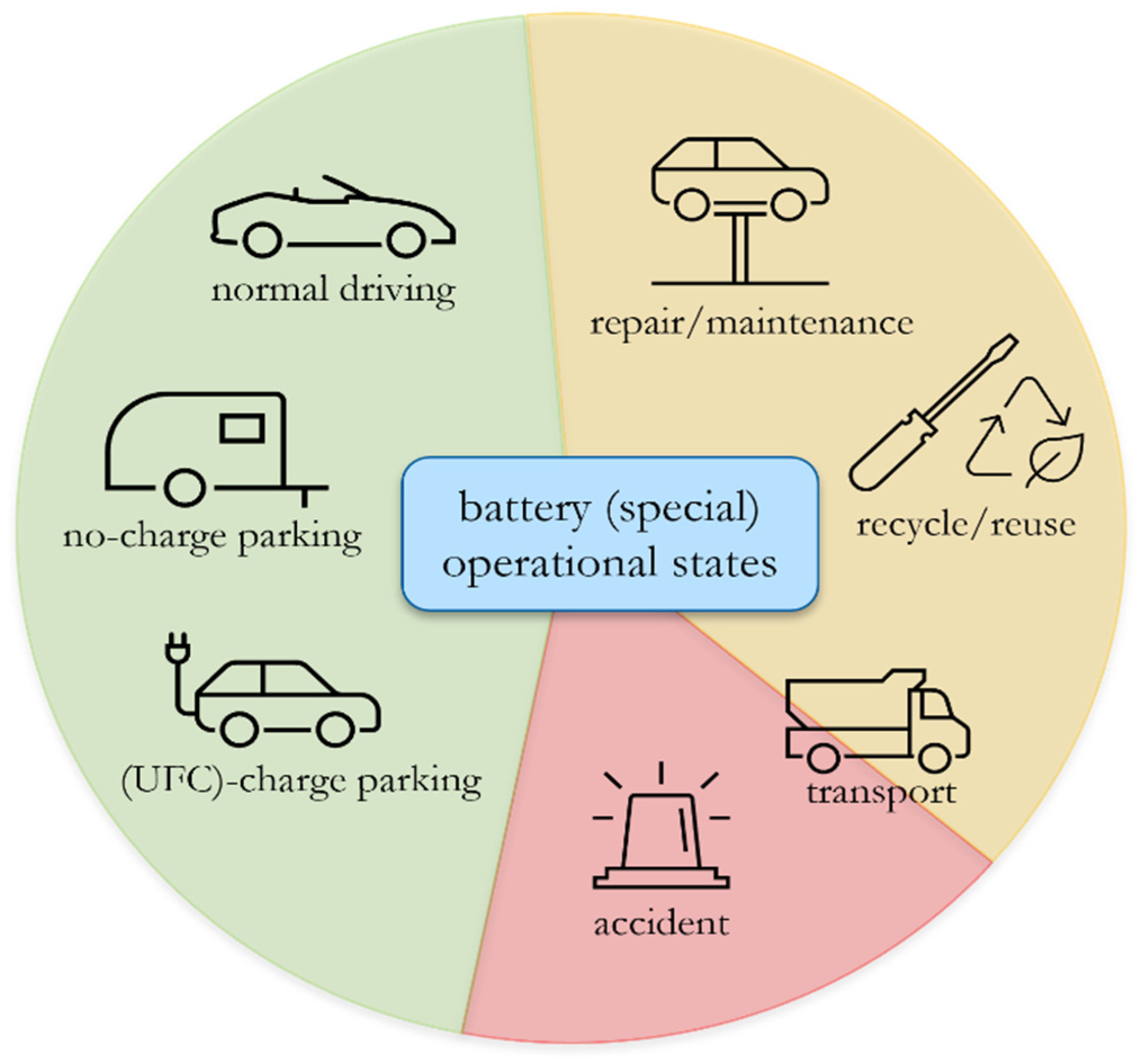
Figure 1 summarizes the different operational states an EV-battery might face during its lifetime. Coded in green, orange and red are the hazard levels present to interactors in the respective situations. For example, normal driving or parking a vehicle is in the green category, since the BMS is most probably fully functional and takes care of observing the battery’s state. In contrast, the orange and red categories summarize the special operational states. When interacting with the system in such situations, the main characteristics are not a fully functional BMS, or an unknown or hazardous state of the battery, and, most importantly, the information about the system’s state must be gathered from an external point of data access, since the battery is either not fully communicative or the battery is not part of a functional vehicle anymore (stand-alone).
Evidently, it is necessary to have a solution for accessing a battery’s internal data, especially when it is not connected to a vehicle, meaning it is a disassembled stand-alone battery and therefore no other options for reading BMS data (like the OBDII-port) are available. Such a solution allows for a further assessment of the respective system and with that ease the planning of required steps (e.g., transport packaging), including raised safety.
3. Factors to Consider for a Stand-Alone Battery Safety Assessment
A stand-alone battery can be (and most certainly is) a system, whose state is not obvious or fully unknown and therefore must be assessed thoroughly. The operational states, where this is the case, are (a) a disassembled battery due to repair work, (b) transportation of a battery (e.g., after an accident) or (c) a battery that is to be evaluated before recycling/2nd-Life.
When approaching such a system, the first thing to better evaluate the situation is a visual check. By that, several impressions can help to classify a simple but essential level of threat the system poses. For example, if the system is mechanically deformed, penetrated by another object, emitting smoke or noises like sizzling and certain smells (i.e., solvent) can be perceived, closer contact shall be avoided. However, even in situations that are not this obvious, a reasonable way to start from a distance is to check the outer housing of the battery, whether it is heated, for example. For this check, a thermal camera or another sort of temperature probe that can be applied with a certain distance could be used. If a battery that has been checked in this way does not show any obvious damages or other signs of harmful evolution, the options of further assessment from the outside get limited quickly. Therefore, a look inside the system is necessary, which is where the BMS comes in place.
To ensure that other systems within a vehicle are aware of the battery’s state, relevant information is communicated in operational states where the battery is fully assembled, as it is the case in
Section 2.1,
Section 2.2 and
Section 2.3. Components such as the power electronics control unit (ECU), the electric motor or generally the vehicle’s board net are possible recipients. Consequently, the whole system can adapt its operating strategy to the state of the battery and vice versa, meaning drivetrain components can request a certain power from the battery, thanks to a comprehensive exchange of battery information.
It is therefore reasonable to consider the concentrated BMS-data stream as a valuable source for the state assessment. However, the term “state” of a battery system is a complex metric to calculate. First, it needs to be clarified what purpose or objective such a state is referring to. In the literature, different states that are already calculated by the BMS are known, whose intentions or indicative values depend strongly on the application and, additionally, most of the described state-values are intended for regular use-case scenarios. For example, the well-known state of charge (SoC) simply indicates the charging level of the applied system. Another intensively discussed characteristic is the state of health (SoH). The SoH is a factor describing the aging state of a battery system, whereas many different methods for calculation are described in the literature. Basically, SoH calculation approaches can be categorized into (a) model-based approaches, (b) data-driven approaches and (c) mixed-approaches. In the latter case, either different sub-methods of (a) and (b) are mixed with themselves or (a) and (b) are both mixed [
27]. Independent of what exact approach is used to calculate the SoH, the goal is equal amongst all of them: derive a factor that describes the level of aging of the system, meaning how its main characteristics, such as capacity and internal resistance, have changed since its beginning, and thus is able to forecast future behavior and performance. The basis for the calculation of the SoH is a model of the desired Li-ion-battery system. Besides rather simple equivalent-circuit-models and electrochemical models including equations that describe ion-movement and thermal aspects, approaches that use data-driven techniques such as statistical filtering or neural networks using large amounts of data try to get a proper SoH result. However, many factors directly impact the accuracy and reliability of this value. These are model accuracy, conditions while parameterizing the models, aspects related to aging covered in the modeling process, the ability of the model to cover and consider interdependencies between aging phenomena and nonlinearities, to name just a few [
28,
29,
30,
31,
32,
33,
34,
35,
36,
37]. Taking this variety of algorithms described only for calculating the SoH, it becomes obvious that this factor is worth including in a safety state assessment, since it might cover lots of internal cell parameters. The side effect is, however, that the value might be complex to interpret since the algorithm applied within the BMS is seldomly known to an external interactor. Consequently, though it might be tempting to take the SoH as a ready-calculated battery state and use it for safety evaluation, this value does not include comprehensive aspects of safety and therefore can be considered, but on its own it is not sufficient for evaluating a battery system’s safety state.
Fortunately, a battery’s BMS contains several other safety and monitoring functions additional to the SoH, SoC and other SoX calculations. Parallel to calculating the excess of aging, the BMS tries to reduce aging as much as possible. To do so, important parameters of a battery system are monitored. These include voltage, current and temperature values of single cells and/or compounds of cells to stay within the abovementioned SOA. The values are key to the balancing function of the BMS, which is necessary to keep all cells within a certain voltage range to avoid unbalancing of the system, which would contribute to accelerated aging or even lead to the destruction of certain cells. An unbalanced system would also have effects on performance since the weakest cell would limit the total usable capacity. To ensure a safe shutdown of the system, the BMS controls main contactors to physically interrupt the electrical connection and disconnect live parts. This is conducted once the battery is in a use-case scenario where no power is required from the battery and no charging is conducted, or when a serious error is detected, and a safety shutdown is required. The system is equipped with redundant contactors to allow for a safe disconnection even in the event of a first failure. Since frequent switching causes the contactors to age, the BMS monitors their state and is able to detect any malfunction or early indicators of such. This is indeed an important function, which allows one to recognize welded contactors that cannot be opened anymore or risen contact resistance in a closed state. Besides redundant contactors, many battery systems have additional options to disconnect the live parts from external components. One of these is the so-called “service-disconnect” (SDC). As stated by its name, the SDC’s main purpose is to allow for a safe system deactivation before maintenance works or any other interaction with an electric vehicle, like it is conducted in car repairs regularly. Moreover, rescue forces such as firefighters are trained to make use of the SDC if equipped, before approaching a wrecked vehicle [
38]. The mechanical fixture of the SDC often comprises the fuse of a battery system, to make use of the easy accessibility and thus ease the repair if required. The fuse is the fallback option of the battery system to interrupt the current flow in cases such as an external short circuit. The SDC is connected to the pilot-line surveillance, another safety function of a BMS. It comprises an electrical connection line that is linked to any removable live part of the vehicle. A test signal input by the BMS is routed through the complete pilot-line and if interrupted, e.g., by removing a plug or the SDC, the main contactors are opened immediately. Another very important BMS-function is the insulation monitoring. Since battery systems are realized as floating systems (galvanic isolation between HV-live parts and chassis-ground), the BMS continuously keeps track of the isolation resistance and informs about faults if existent.
Additional to the aforementioned monitoring function, which is conducted by the BMS itself, other helpful values can be considered. Since the BMS is communicating with other ECUs inside the vehicle in normal operational use cases (e.g., motor ECU, inverter ECU, airbag ECU), there might be valuable information that is not directly measured by the battery itself but placed inside its BMS storage to be read out even in the stand-alone scenario. An example for such a message is the “crash-detected” signal, which might act as an HV-shutdown request initiated by the airbag ECU in a crash-scenario, before a probable failure of the system. This information could be of use in case of a battery system of unknown history for further assessment of its safety state.
Summing up the various information a BMS is collecting, it is reasonable to consider it in its entirety once evaluating the battery’s safety state. Cabrera-Castillo et al. have defined a so-called “state-of-safety (SOS)” as the inverse of a state of abuse, a function that takes several parameters, such as voltage or temperature that are in relation to the system’s behavior. In addition, faults such as mechanical deformation, which could be visually detectable, or derivatives of certain battery parameters are considered. The latter factor is rather important for in-life safety evaluation, e.g., as the BMS does during first life of a battery [
39].
As summarized by
Table 1, a lot of useful information is stored within the BMS, which induces a reasonable motivation to physically connect to it and read out the available data.
4. Physical Access to Battery-Relevant Information
To assess the practical options for obtaining physical access to BMS-originated data, the interfaces for a connection need to be known. As deduced in
Section 2, those interfaces differ depending on the operational state, whereas the difference is mainly linked to whether the battery is part of a fully assembled vehicle environment or a stand-alone entity. Therefore, mainly three situations can be mentioned, which are: (a) vehicle with integrated battery system in normal operation, (b) stand-alone battery decoupled from a vehicle and (c) vehicle equipped with a battery system involved in an accident.
Table 2 links the means of data access with the operational states and the respective assembly situation.
4.1. Situation (a): Battery Assembled Inside Vehicle
In this case, the BMS takes care of the operating strategy, state observing and communication of data to the rest of the vehicle, which is often conducted by a controller area network (CAN) bus. It is therefore possible to sniff data from such a communication line, e.g., between the BMS and the inverter ECU, while they exchange information. Needless to say, this requires some manipulations to enable a physical coupling into the communication lines (two in the case of CAN–bus).
Considering regular ICE vehicles, the OBDII-port sure is the main data access point to the vehicle’s system network. Regulations force ICE vehicles to have such a port, making several emission-related checks possible as well as an eased maintenance by storing error-codes or actuator states, which is intensively used by car repair workshops or during regular technical inspections. However, there is no binding regulation to date that forces EVs to come equipped with an OBDII-port, although some manufacturers supply their models with this port. This is especially the case for (P)HEV-vehicles [
23,
40,
41]. Even if an electrified vehicle was equipped with the port, the information exchange would not be covered by a regulation and, therefore, the vehicle manufacturers can implement proprietary solutions, including either special reading tools or limited functionality in terms of information disclosed, or both. For example, Toyota, Lexus, Nissan or Chevrolet equip some models with OBDII-ports and enable customers to connect to it, to take a look at some limited parameters of its battery (e.g., voltage, temperature, SoC). However, the main purpose of this data supply can be considered as an “entertaining” feature. In addition, a proprietary application is required, and the information is not evaluated in terms of safety. Other electrified vehicles offer the OBDII-port access with common diagnostic tools, but limit the information available [
42,
43,
44]. Nevertheless, if an OBDII-port is available, including relevant data traffic, this sure is the most straightforward and preferable physical access to BMS-originated information.
Considering the safety concerns in these fully assembled battery scenarios as discussed in
Section 2, the available data access points do not require a closer or direct contact with the battery, which means this can be conducted without high risks. Moreover, the motivation to do so might not be as high as in other situations, at least in terms of a safety assessment. If the latter was, however, necessary in special cases as described in
Section 2.3 and
Section 2.4, the information could be accessed depending on the implementation conducted on OEM-side.
4.2. Situation (b): Stand-Alone Battery System (Decoupled from Vehicle)
This situation is worth taking a closer look at, since an interactor is facing a stand-alone battery with only the mere interface of the BMS, which would connect to the rest of the vehicle in situation (a). In addition, although the main (high) voltage terminals underly an IP protection class that shall prevent direct accessibility [
45,
46], they are not connected to other systems in this case and thus might be potentially accessible with certain objects. At least as long as the state of the main contactors is unknown or the terminals are otherwise proven as non-live, raised caution is sensible.
For the evaluation of such a stranded energy storage system, there are basically different ways to proceed. For example, the main terminals could be used for complex cyclization tests to determine variables such as capacity and internal resistance. Impedance spectroscopy could also deliver information about the electrochemical state. Both methods, however, require a lot of time in execution. Furthermore, they cause considerable costs due to the necessary equipment (test benches, measurement technology) and in addition, their use and the execution of the measurements as well as the assessment of results are complex, which would require the interactor to have advanced expertise. In addition, a working BMS communication is mandatory as well since the main contactors would need to be switched if electrical tests were intended. While such investigations can be conducted under laboratory and stationary conditions, the factors time consumption, complexity and sophisticated equipment disqualify these evaluation procedures for “mobile” uses, which is given in a situation where a battery is a stand-alone unit and needs to be packed and transported (see
Section 2.6 and
Section 2.7). In such a case, an efficient assessment is essential to be able to take prescribed transport measures quickly. Additionally, the people handling such situations (e.g., employees of carriers, waste disposal companies etc.) are experts in logistical matters rather than having special knowledge about battery systems and its threats. At least, it cannot be taken for sure that everybody involved in the process has undergone special training. Consequently, the BMS communication interface is the only remaining option to gather battery-relevant information. As a matter of fact, though, it is not just straightforward to connect to the BMS, since no working board net with a low voltage supply is present and it would recognize that the counterpart is not a vehicle with other participants. In this case, the BMS would refuse any communication. Thus, some efforts need to be taken to make the BMS believe it is communicating with a car, in order to get it to deliver useful information.
4.3. Situation (c), Vehicle Involved in an Accident
This case needs to be discussed irrespective of the severity of the accident. A vehicle that has been involved in an accident is posing several problems at once. For the firefighters responding to an electric vehicle crash, it is not straightforward to assess the possible threats that arise in such a situation. First, it might not easily be detectable that an electric powertrain is present (i.e., due to severe mechanical damage or simply due to design reasons). Second, the crash impact can lead to serious consequences inside the Li-ion battery, which might lead to delayed effects such as thermal events long after the crash had happened. It is even possible that an extinguished fire can reignite after a certain time [
47]. Wöhrl et al. have discussed possible handling recommendations for crashed electric vehicles in the case of Germany. After a first visual observation, they propose to additionally evaluate the situation with an acoustic observation (venting noises, etc.), thermal observation from a distance and a gas analysis, focusing on detecting smells arising from the system (i.e., solvent’s characteristic smell or smoke). Depending on this observation, the hazard state of the vehicle’s battery is determined. However, they also state that a comprehensive assessment without an inside view into battery data is not fully possible [
25].
Now there are several obstacles that make reaching the physical BMS data port difficult. Different from the situation in
Section 4.2, the battery is still assembled inside the vehicle and thus no easy access is possible. In addition, many rescue strategies include cutting the low-voltage power supply of a vehicle (regardless of whether this had happened during the crash due to mechanical impact) to avoid further activation of board net components or sudden airbag blowups [
38,
48]. As mentioned above, a disconnected low-voltage supply deactivates the BMS and thus no data are communicated. When comparing this case to
Section 4.1, the situation is similar in terms of the assembly state, although mechanical deformations might worsen the accessibility. In contrast, however, the need for reading BMS-internal data is higher since it would contribute to a safer handling of the crashed vehicle. In any case it must be considered that this situation is the riskiest one in terms of approaching the battery. As a consequence, it is reasonable to tow the crashed vehicle first to a safe storage place and wait a longer period before taking further steps, to avoid hazardous situations if the battery system catches fire belatedly.
To sum up the discussions in this section, there are mainly four options for getting battery-related data for performing a state assessment (see
Figure 2). First, there is a sense-related observation including visible, acoustic and thermal inspection, as well as detecting exhaust fumes or smells. Second, using the OBD-port is possible, dependent on the vehicle type and implementations regarding relevant data traffic at this connector. Third, a direct access to the BMS-data interface can be established, which is mainly possible if the battery system is not assembled inside a vehicle. The last option is performing electrical measurements at the main voltage terminals of a battery, which can be considered the most comprehensive way, whereas it is the one requiring the most effort together with a working BMS-communication to get the main contactors closed. It becomes obvious that the case of a stand-alone battery is the most interesting and yet demanding one, since no low-voltage board net supply is present to activate the BMS and no OBD connection is possible, which could be supported by manufacturer-specific diagnostic tools. In addition, this case will become more frequent in the future, since transporting batteries or storing them for second-life applications further increases with the electrification of mobility. Thus, the stand-alone battery is considered the main use-case of a quick safety-state-determination method, which is described in the following.
5. Proposed Method for Quick State Determination Independent of Rest of Vehicle
Besides some proprietary solutions from OEMs as mentioned in
Section 4.1, there are currently no solutions for a mobile and quick safety state assessment of stand-alone batteries without expensive or special equipment. To take the example of a transport, it is common practice to either consult experts for an assessment (e.g., the manufacturer) or to transport the storage units in highly stable packaging equipped with many safety features [
49]. For the former method, it is additionally difficult to get experts that are aware of different types of systems. Often, the choice depends on the brand of the battery in a certain case. Both approaches are highly inefficient and cause very high costs. This fact carries even more weight when it comes to facilities such as waste disposal and recycling companies or battery collectors, who need to transport, store and check the systems on a regular basis. For them, the beforementioned measures such as consulting experts or taking highly advanced packaging strategies are of no practical use and far from being economically feasible. Consequently, to make a step towards such practical applications, there are several requirements a quick and mobile solution shall have, which can be summarized as follows:
The solution shall allow for an assessment of a battery’s state, whereas the term “state” is to be defined according to the application of interest, e.g., safety evaluation.
Information must be extracted from the system and displayed in a comprehensible way to take measures accordingly.
Different types/brands of batteries must be assessable.
No highly advanced or auxiliary devices shall be necessary.
The solution shall be intuitive and easy to handle.
The solution must ensure a maximum of safety for the user.
Therefore, a device that connects to a battery system to read out safety-relevant information from the BMS has been developed, further referred to as mobile interface. This mobile interface, consisting of a mobile hardware and an application (for mobile devices such as smartphones), facilitates a battery’s safety state assessment, as it quickly collects data from the BMS. Then, it evaluates the received data, followed by a comprehensible way of displaying the result. It is highly oriented toward a mobile applicability, meaning the interface is very small and does not require any additional power supply or other auxiliary devices, since it is equipped with its own power source. To get information from a battery, the device connects to an existing communication channel to the BMS, which mostly is the connector used for communicating to the rest of the vehicle in regular use cases.
Like the battery-data related OBDII-communication, the BMS-communication is not standardized either, which affects the communication protocol as well as the physical access (connections or plugs). Thus, the developed mobile interface is implemented in an expandable way and is based on a central database/backend concept. It enables a versatile application for multiple brands and types of batteries. In addition, the operation of the mobile interface can be learned intuitively and is therefore easy to apply even for non-expert users, which enables, i.e., employees of waste management companies, transport or towing companies as well as rescue forces such as firefighters to make an assessment on site, for the sake of safely handling it for a short time. Besides this concept of connecting the mobile interface to the existing BMS-datalink, it is also possible to expand the application towards full vehicles, where an OBDII-connector could be used for connection.
Figure 3 shows the connection principle, which can be adapted to different types of batteries.
5.1. Hardware Implementation
Since most manufacturers use proprietary connections in their batteries for data communication, the developed hardware must offer the possibility to plug in any connector with suitable adapter cables. For this purpose, a connector that provides communication channels (for reading multiple data streams simultaneously, if required) and a 12 V battery to supply the BMS with energy is equipped. In normal operation, this power supply would be the vehicle’s board net, but in stand-alone situations—when only the battery is available without the vehicle—this is no longer the case. Therefore, the mobile hardware takes over the power supply and simulates an ignition on signal as it is present in the normal operation of the vehicle in field.
Considering the case of a battery whose data are to be read from the BMS, an appropriate adapter cable must be used, which allows for connection to the mobile hardware on one side. The battery-side requires the matching plug of the connector assembled in the battery. With the proper pin assignment—which must be known for the connection—the corresponding data lines can then be adapted to the data channel pin-assignment of the mobile hardware. Consequently, the task of preparing adapter cables with the correct wiring must be conducted only once, whereas it shall be mentioned that a standardized connection to the battery’s BMS would ease this process a lot. In current vehicles, this communication channel is mainly CAN–bus based [
50], meaning that the hardware to read and understand the BMS-data must be prepared for that protocol. Hence,
Figure 4 illustrates the physical input of data to the mobile interface.
After the hardware has been connected to the BMS, it can be supplied with power via the internal 12 V supply of the mobile hardware. At the same time, the “ignition-on” signal is connected to the 12 V supply of the mobile hardware, so that the device simulates a regular situation. The BMS will then start to transmit battery-related data to the communication lines, just like in a use-case as described in
Section 2.1. (driving). In that case, the BMS believes that there is a working connection to a vehicle.
Once data are communicated by the BMS, the CAN-peripherals inside the mobile interface take care of a proper acknowledgement of data, which is required by the communication rules of the CAN–bus protocol. If no such acknowledge signal is sent, the BMS ECU will assume that the transmission was faulty and in the worst case will stop communicating if it is repeated several times (based on an internal error counter) [
51]. Based on this transmission protocol, any overhead in the received signal (length information, checksum, etc.) is separated from the user data and only the latter is processed. The other information is not relevant for the further processing steps. The communication periphery forwards the data to the central communication node, a microcontroller, where they are finally packed into a transmission protocol and sent wirelessly to the second part of the mobile interface, an application that is further referred to as “BatteryCheck”. This application is discussed in
Section 5.2.
In general, a key question is what information is available on the connected data channel. While the information gathered inside the BMS is mainly identical amongst most of the battery manufacturers, this is not the case when it comes to the communicated information towards the rest of the vehicle. This is because some of the information is processed only within the BMS and never communicated to the outside, since it is only required for calculations such as SoC or SoH. This is another side-effect of the lack of standardization. The information itself can be defined and altered by the will of the manufacturer. However, there is a minimum of data values that most certainly are communicated to the powertrain, which can then be read from the communication interface. These are battery voltage, temperature, current, capacity, state of charge, power and other signals, such as actor states (i.e., main contactors), error messages and status flags. In some cases, the single-cell voltages and/or temperatures are available at the main communication port of a battery, which, however, can be considered a lucky or seldom situation.
5.2. Application “BatteryCheck” for Data Display and Assessment
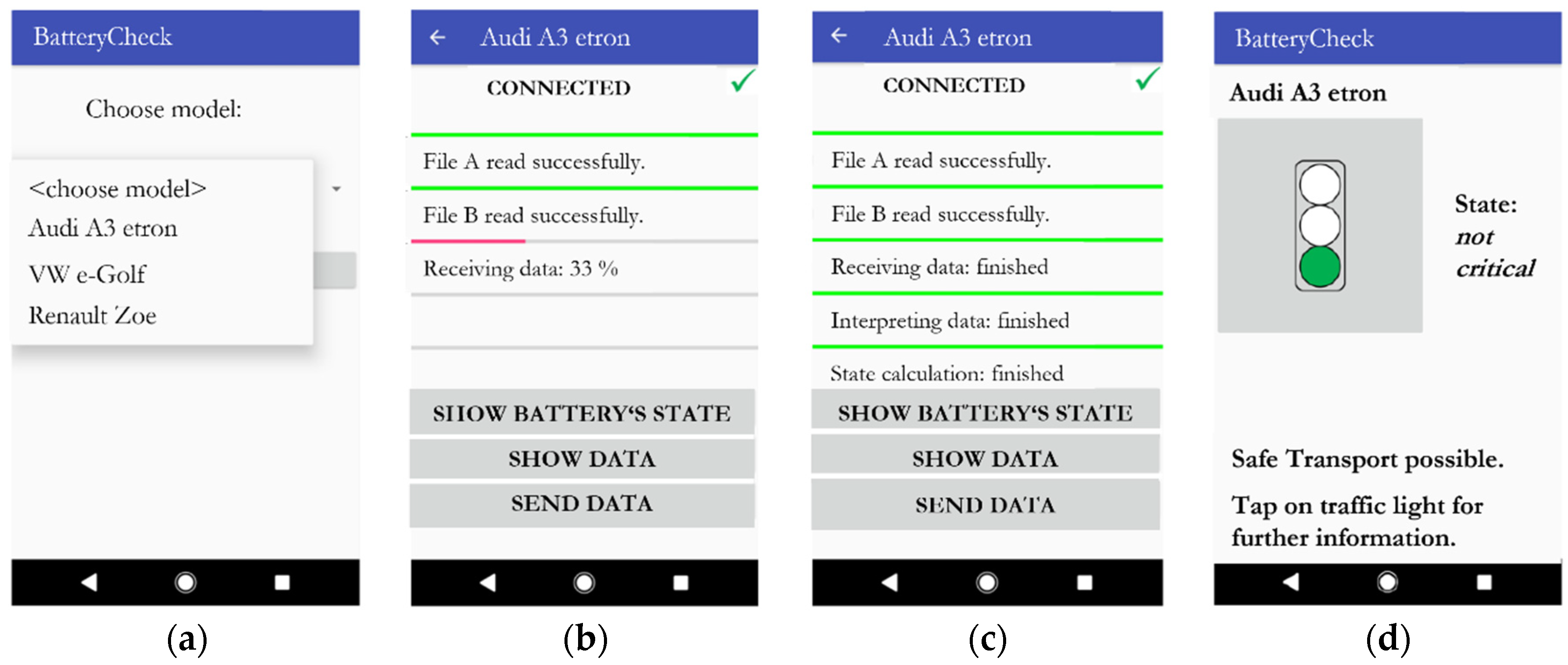
To view the information that was captured by the mobile hardware, an application “BatteryCheck” was developed. Since nowadays nearly everyone has access to a smartphone, it is sensible to run the app on such a device. This also goes in line with the overall mobility concept of the mobile interface since it is easily accessible and always available on site. Once opened, the user can choose from different battery models the app gets from a backend database, to initiate the connection to the hardware via Bluetooth Low Energy. After successful connection, the capturing of data starts. The hardware will then continuously transfer the battery data directly to the app, where it is first decrypted, then interpreted and finally displayed. All this calculation takes place in the smartphone (or other device) the app is running on. This allows for a very simple hardware used in the mobile interface itself, since little to no processing power is required.
Figure 5 shows the different views the app provides to the user.
After the user has chosen the respective model, the app will start querying a database it is connected to. In this database, all information about the chosen model is stored. This contains information about the battery itself, such as number of cells, cell chemistry, overall voltage, etc. In addition, information about what data values can be expected at the physical data line is available. As mentioned above, the information communicated to the outside of the battery is mostly manufacturer dependent and differs between models. To assess the data, the decryption offsets and factors for interpreting the raw CAN-data, as well as the algorithm to interpret the data, are stored in the database. Since the available information is model specific, the interpretation algorithm also is. Thus, the algorithm must be developed once for a specific battery model and then placed in the backend database, for being used by the app. Basically, the information processing consists of three main steps, as the data context illustrated in
Figure 6 shows: (a) read model-specific files from database, (b) receive data from mobile hardware and decrypt, and (c) interpret data according to the model-specific algorithm.
Step (a) is a simple connection to the cloud, which downloads the appropriate information for the selected battery model. In step (b)—decryption of data—the downloaded file is used to get the physical values from the data stream, which until this point is just a collection of bits, without a senseful meaning. Thus, the information that is stored in the backend includes structures as demonstrated in
Table 3.
It shall be noted that the shown information is just an example and does not apply to any specific battery model. However, it becomes clear that this important information must be known to get the physical values. This requires a one-time generation of such a file, which can be conducted by an expert in the field or by the manufacturer. The column “CAN-no.” refers to the respective connection at the main plug of the mobile hardware. In case that more than just one CAN-channel needs to be read from the BMS, this can be considered by adding additional CAN-messages to the backend-file.
Another key part of the state assessment is the algorithm according to which the data are to be evaluated (step c). This information is—as mentioned above—also vehicle/model specific and must be stored for the respective model in addition to the decryption data. The evaluation rule is implemented in the form of a decision tree, where each node corresponds to a battery relevant information (e.g., current value, overall voltage, battery temperature, etc.). Depending on their value, a decision is then made, which results either in a jump to another node or the end of the calculation, i.e., a final state estimation.
Figure 7 shows the principle of data evaluation.
Decision trees are directed trees consisting of nodes and edges leading to so-called leaves. There are generally multiple paths that can lead to different outcomes. In each case, however, there is a leaf at the end of a path that is a result. These result leaves are also called terminal nodes because they lead to the termination of the algorithm [
52].
The starting point is the so-called root node of the tree. In each node, decision rules, i.e., attributes of the node, are checked. Each result of the check leads to another edge leading to the next node (or a leaf). The edges are thereby assignments of the attributes of a node, whereby it is distinguished between nominal and numeric attributes.
The input is data that are mapped to a classifier. Mathematically formulated, the mapping function is:
where
X is the input data and
Y is the classifier, meaning a decision of the tree.
Now, this theory is applied to the concept of the mobile interface. To do this, a set of data are defined to serve as the input vector for the tree. Since the file in the backend database contains the communication matrix and thus all messages read from the BMS, it serves as such a set of data. From them, a subset is selected as input vector for the tree, which are relevant for the safety-related assessment:
where
X is the input data of the tree and
C are the messages stored in the communication matrix file.
The attributes of each node can only be numeric ones, which are assigned the values true or false:
Here,
g is a test function, which is applied to the message
n.
n is element of
X, the input data to the decision tree. An example in the application of the mobile interface could be:
n = voltage,
g: n < 390 V
→ {true, false
}. The criterion for a termination of the algorithm is a state, meaning a risk assessment represented by a traffic light color. Consequently, the tree algorithm for the mobile interface can be summarized as
f: X → {green, orange, red, orange/green, orange/red
}.
Table 4 shows an exemplary implementation of a model-specific algorithm, which is stored in the database.
While assessing the received data, the app goes through the algorithm starting at node 1. For every node, the test function is applied, and the decision is taken accordingly. The assignment of the node number to the respective battery data is conducted by the CAN-message name, which is stored in an equal way in the communication matrix. Once the algorithm has reached a state-node, the calculation terminates and notifies the user that the calculation has been finished. After that, the user can view the result (
Figure 5d) and take appropriate measures (i.e., choose the suitable transport packaging). To make sure that the application is intuitive, the calculation result is presented as a traffic light system. This guarantees a simple readability of the evaluation. In addition to just viewing the evaluation, the data and the calculated result can be sent by any means offered by the device the app is running on. This enables, for example, a more detailed analysis of data in a central headquarter such as a towing company’s headquarter for documentation or training purposes.
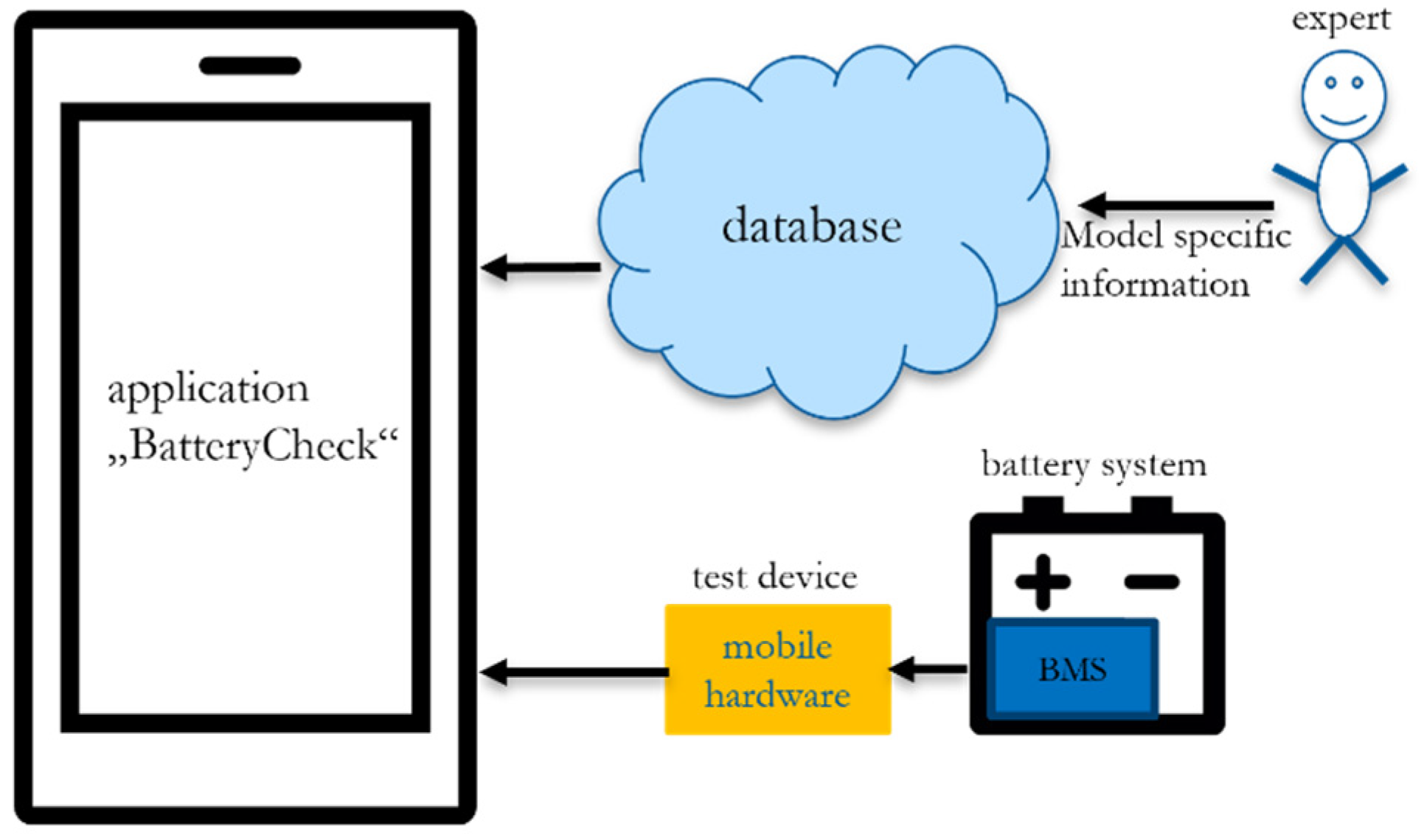
To sum up the principle of the introduced mobile interface,
Figure 8 illustrates the complete system context.
Like the decryption information, the evaluation algorithm must be created by technically experienced personnel. This can be conducted, for example, based on manufacturer information, but preferably by introducing a standard for the rapid evaluation of traction batteries. Since the evaluation is exclusively based on the received data from the BMS, it is very easy to comprehend the reasons the algorithm came to a certain decision. This is not only a highly useful characteristic of the device when it comes to documentation; it also enables a constant improvement of the backend database content. This can be for integrating in-field experience when using the interface, but also to adapt the assessment algorithm to certain applications, such as safety assessment for transport preparation vs. regular checkup while storing the system vs. extent of degradation. Especially in the complex latter case of evaluating the degradation states of batteries, highly sophisticated methods using neural networks like in [
53] could be integrated to support the application.
6. Results from an Example Application and Discussion
To test the concept of the mobile interface, a real vehicle’s battery was used for application. The first step was to create the communication matrix, including the available CAN-messages to be read out of the BMS. This could then be used as a base for implementing the evaluation algorithm.
Table 5 shows the respective CAN-messages available at the used example model.
For the listed messages, the decryption data were known to the authors. Since this information including the exact test model would be of no further use for the demonstration, it is not described herein.
The second and main step is to define the algorithm for evaluating the received BMS information. For that, the purpose or application scenario must be considered. This means, to have a suitable assessment for a certain use-case, the main characteristics of the latter must be known. In this test scenario, the interesting case of a battery transport was taken. For handling a battery transport, its safety state must be evaluated to take packaging and documentation measures accordingly [
4]. In addition, the safety focus is important since the packer of the entity might not be an expert in the field. To support this, the user of the mobile interface shall get a comprehensive evaluation result together with easily understandable instructions or information that is useful for the necessary actions.
It shall be noted that the shown messages are not the only ones that were communicated by the test battery’s BMS. However, other messages, such as the maximum usable energy or comparable ones, were not adding any value for assessing the situation in terms of preparing a safe transport. Here, the information about the error state or the safe shut-down of the system was of higher importance. In contrast, however, information about single-cell voltages were not communicated to the outside of the BMS, which would have been of great use if known. Since the structure of the evaluation algorithm depends on the chosen messages, it is also application dependent and thus the result is strongly aligned with its specific characteristics and can be easily adjusted to another case. This, on one hand, ensures an easy traceability and understanding of a certain evaluation; on the other hand, it keeps the algorithms compact and tailored for a certain use-case.
Based on the shown messages, the evaluation algorithm was created. As mentioned, the safety aspect for the interactor in the transport case is of highest interest. Hence, the evaluation behavior of the algorithm is rather sensitive to inform the user about potential threats. The following figure shows the implementation.
Depending on the CAN-message values, the algorithm can have multiple states resulting out of its calculation. The example shows all five possible states. For example, an orange/green state signals that a safe transport is possible; however, there are additional actions the interactor can take to further improve the level of safety, e.g., by removing the service-disconnect. In contrast, an orange/red result is advising the user about actions to be taken or information which require special attention. Obviously, the red state is the most critical one and will inform the user about a threatening condition of the battery. The green state is only reached if all criteria are evaluated positively, meaning there is no error, all values are within the intended range and the service-disconnect (abbreviated as SDC in
Figure 9) is not plugged in. The reader might wonder about the voltage criteria given in the example. This was due to the test battery’s voltage level, whose maximum limit was below 400 V. When looking at the different state results in
Figure 9, it is possible to add information after the ‘*’-identifier. This must be conducted in the algorithm structure shown in the previous section and will be displayed to the user after hitting the “further information” button, as shown in
Figure 5d). The evaluation of the safety state is finally shown in the traffic-light view in the “BatteryCheck” app.
As demonstrated by the transport use-case, accessing BMS-internal data is easily possible under several circumstances. First, the battery of interest must provide a physical access to its BMS, which is the main connection to the vehicle’s board net in an assembled situation. Second, the pinout of this connection must match the adapter cable of the mobile interface, meaning this information is obligatory as well. Third, the messages to be expected at the data port must be known, including their encryption information such as factor and offset values, which are often applied according to the CAN–bus protocol. If all this is known, the mobile interface enables one to read such data, as well as interpret and display it.
However, there are several factors that need to be considered when applying the mobile interface. Reading out BMS data from a stand-alone battery means that this is just an insight into the current values, such as voltage, error messages or flags. There is no information about the history a certain battery went through, which would be helpful for assessing the evolution of certain parameters. Since the implementation of the communicated data is not yet uniquely standardized, it also cannot be considered that the information is reliable in any case. Imagine a defective sensor inside the battery, which is contributing to a certain decision of the algorithm. If the falsified result leads to the indication of a more critical state than it actually is, this is not a serious problem. In fact, it might lead to a more expensive transport due to safer packaging, for example. If the result is, however, falsified towards a more positive evaluation, this can lead to serious consequences for the user. From what is communicated to the outside of a battery, there is no possibility to validate the integrity of measurement values, except values being way outside of the expected range.
Another fact to recall is that the evaluation algorithm in the database needs to be implemented according to what data are available. Depending on the use-case scenario, the communicated data are to be interpreted differently, which might lead to several versions of an algorithm. In addition, regional differences in regulations must be taken into account, especially when the algorithm delivers handling recommendations (e.g., packaging). Taking the situation that an expert should manage this task, a clear structuring and accessing of the versions must be conducted in parallel to avoid confusion or wrong interpretations. The usefulness of the evaluation results can also differ depending on the respective use-case and the users’ knowledge or background. For the shown example of a battery transport, clear and descriptive results indicating packaging suggestions are helpful for a probably non-battery-experienced user. However, other applications of the introduced method, such as a regular checkup of stored batteries, might require a numerical safety-evaluation result, similar to that commonly used in SoH calculations, to track changes or allow for further processing.
Recalling the situation an interactor is facing when handling a stand-alone battery, gaining access to such BMS data can be very useful. However, considering the discussed obstacles that must be overcome for an application, the use of the mobile interface should not be taken as the only evaluation criteria for taking any actions. It is more to be understood as an additional tool on the way of gaining a comprehensive insight into a battery, which is desirable for enhancing the safety of involved parties.
7. Conclusions
In this article, it was shown that modern electric vehicles offer a few options to collect battery-relevant data for state assessment purposes, which are required in several situations. A highly important factor that should be considered in all of them is the safety of involved parties while interacting with or handling the system. When comparing the different situations, it becomes clear that mainly two need to be distinguished: a battery still assembled inside a vehicle and a stand-alone battery without the vehicle. Considering the urgency of having battery data, the second case is the more interesting one, because in the first case accessing data is trivial. In case of the sole battery, the involved persons have little to no quick or mobile possibilities to assess the safety state of the batteries to date. Thus, a versatile approach to collect battery-related data was introduced, which is connecting to the battery’s BMS-port and communicates data wirelessly to a connected device. This enables the viewer to analyze the current state of the system in terms of safety with the developed application and take actions accordingly. However, a big stumbling block in the process is the fact that currently there is no standard that defines a minimum set of information to be offered via a standardized interface. Neither the physical access nor the communicated data are uniquely defined so far. Therefore, the developed mobile interface offers a unique connector, which is equipped with several communication lines to be adapted to a manufacturer-specific connector. This does not solve the problem of proprietary battery connectors, but it allows for a single mobile hardware to be used for different models with the help of adapter cables. The user of the hardware therefore will not have to get used to different devices, which makes an application easier and more efficient. To tackle the problem of proprietary data protocols, the application makes use of a database that can be fed with model-specific information remotely. This allows for, on one hand, expanding the applicability of the mobile interface to practically any battery model; on the other hand, it does allow for a tuning of the evaluation algorithm. The algorithm must be developed with expert knowledge, but otherwise is adjustable to the data readable from the BMS. Therefore, the application is not only versatile with respect to different models, but also with respect to the intended use-cases. As a further improvement, the estimation algorithms could be expanded with battery models, which would allow for checking the integrity of the received information up to certain levels. Many applications and stakeholders could benefit from the solution, starting from repair works, or technical inspections conducted by service technicians or engineers, transported systems including checkups in a battery storage location conducted by towing, transport or recycling companies as well as first responders (firefighters, police officers) approaching an accident scenario.
These facts show that a quick and mobile safety state assessment is very feasible, but it, moreover, leads to the conclusion that it will be a crucial improvement in the future to introduce a standard, which defines a decent set of battery parameters to overcome the mentioned hurdles of connection and data communication. Thus, the physical interface for data collection as well as power supply must be defined. This could be either a standardized plug-connection or even a wireless interface. The latter would be a highly elegant as well as useful solution, not only for a transport use-case. Considering the case of an accident, a wireless interface transmitting those standardized battery parameters would allow the rescue forces to evaluate the state from a distance, preventing them from being exposed to danger. The implementation of the herein introduced mobile interface is already prepared to communicate wirelessly, in this case via Bluetooth Low Energy. However, in a fully wireless scenario the question of the power supply for the BMS to enable communication must be answered. In this case, a solution that could be thought of is a small microcontroller with a wireless communication ability, which continuously stores the most important and safety-relevant battery parameters, fed by the BMS. When a crash takes place, the “crash-detected” signal sent by the airbag ECU could initiate the supply of this PCB with, e.g., a primary battery for a certain time, once the HV-battery is shut off.
Considering a standardized battery data exchange, it sure should be driven by policy, to ensure an adoption of advanced second-life processes and support interactions as described above with a high focus on safety. However, the vehicle manufacturers might also benefit from such a standard. First, it could simply make EVs more attractive to customers, if there is a higher transparency, e.g., in terms of receiving information about the battery’s life expectancy and its state during lifetime. Second, the provision of spare parts could be eased for the manufacturers. Considering new business fields, where battery collectors store and treat assessable batteries and parts (thanks to a standardized data exchange), manufacturers could share efforts or extend the provision of spare parts with such companies, reducing the need for producing new parts. Last but not least, it will lead to a more sustainable use of resources, which not only sounds good, but is an indispensable point in these times.
Finally, it can be said that a proper standardization work for the exchange of safety-relevant battery information will be a big achievement by contributing to enhanced safety for people handling batteries of any kind, which is most desirable.


