Review

Recent Development in Carbon-LiFePO4 Cathodes for Lithium-Ion Batteries: A Mini Review †

by
Brindha Ramasubramanian
1,2,
Subramanian Sundarrajan
1,
Vijila Chellappan
2,
M. V. Reddy
3,
Seeram Ramakrishna
1 and
Karim Zaghib
4,*
1
Center for Nanotechnology and Sustainability, Department of Mechanical Engineering, National University of Singapore, Singapore 117574, Singapore
2
Institute of Materials Research and Engineering (IMRE), Agency for Science, Technology and Research (A*STAR), #08-03, 2 Fusionopolis Way, Innovis, Singapore 138634, Singapore
3
Nouveau Monde Graphite, 481 Rue Brassard, Saint-Michel-de-Saints, QC J0K 3B0, Canada
4
Department of Chemical and Materials Engineering, Concordia University, 1455 Boulevard de Maisonneuve, Montréal, QC H3G 1M8, Canada
*
Author to whom correspondence should be addressed.
In honor of 100 years birthday of Prof John Goodenough.
Batteries 2022, 8(10), 133; https://doi.org/10.3390/batteries8100133
Submission received: 16 May 2022 / Revised: 9 September 2022 / Accepted: 14 September 2022 / Published: 21 September 2022
(This article belongs to the Special Issue Anode and Cathode Materials for Lithium-Ion and Sodium-Ion Batteries)

Abstract

:
Li-ion batteries are in demand due to technological advancements in the electronics industry; thus, expanding the battery supply chain and improving its electrochemical performance is crucial. Carbon materials are used to increase the cyclic stability and specific capacity of cathode materials, which are essential to batteries. LiFePO4 (LFP) cathodes are generally safe and have a long cycle life. However, the common LFP cathode has a low inherent conductivity, and adding a carbon nanomaterial significantly influences how well it performs electrochemically. Therefore, the major focus of this review is on the importance, current developments, and future possibilities of carbon-LFP (C-LFP) cathodes in LIBs. Recent research on the impacts of different carbon sizes, LFP’s shape, diffusion, bonding, additives, dopants, and surface functionalization was reviewed. Overall, with suitable modifications, C-LFP cathodes are expected to bring many benefits to the energy storage sector in the forthcoming years.

Graphical Abstract

1. Introduction

The growth of renewable energy technologies and the electric vehicles market requires developing low-cost batteries with high energy density. With high operating voltage (~3.2 V to 3.4 V), and relatively high capacity, Li-ion batteries (LIBs) have been used popularly in electric vehicles. However, the energy density of LIBs is often limited by the low electrochemical capacity of cathode materials (<200 mAh g−1) and the poor rate performance of the electrodes. LiCoO2 was the first commercially used cathode material (i.e., used by SONY electronics) in LIBs; however, it causes environmental pollution during manufacturing, overcharging while being used, posing a possible safety concern, and is costly given the low storage capacity [1]. LiNiO2 has an affordable price and analogous crystal structure to LiCoO2; regrettably, it is challenging to manufacture and has limited temperature and rate capability. Although the spinel structure LiMn2O4 is reliable and easy to make, the Jahn–Teller distortion in the lattice often during the cyclic process causes it to deform, leading to fast degradation of capacity, particularly at high temperature and stress levels. Lithium iron phosphate (LiFePO4) cathodes are relatively safer to use and have longer cycle life than LiNi1−x−yMnxCoyO2 (NMC) and LiNi1−x−yCoxAlyO2 (NCA) cathodes [1,2,3]. Though NMC cathodes account for a higher market share than LFP, Companies like Tesla are switching to LFP cathodes due to their long cycle life and thermal stability, up to 270 °C [4].
Destenay discovered LiFePO4 (LFP) in triphylite mineral solid solutions, forming olivine and isomorphous structure with Li phosphates of divalent Mn and Fe. Remarkably, Prof Goodenough and his colleagues’ ground-breaking work demonstrated the possibility of extracting Li from LFP using an insertion method for the first time [5]. He foretold the stability of sulfides, and phosphates at high oxidation states and mentioned the higher potentials (>3.2 V Vs. Li/Li+) for transition metal oxides [6]. Besides these efforts, LFP exhibited a low intrinsic conductivity reducing its operating efficiency. Prof Michel Armand and his coworkers postulated that adding carbon materials to LFP cathodes would be able to significantly improve their performance, allowing them to achieve a practical, reversible capacity comparable to the theoretical value (~170 mAh g−1). LFP rechargeable batteries have high specific energy (90–170 Wh Kg−1) and high volumetric energy density (1200 kJ L−1), indicating that they can deliver the required energy for powering EVs and grid; it is also important to note that specific LFP-based batteries offer good cyclic performance (~1500 cycles) with nominal cell voltage (~3.2 Vs. Li/Li+) and in commercial scale (18,650 cells) offers the cyclic performance of 10,000 cycles at 0.5 C, reported by Preger et al. [7]. LFP is a benign substance that does not emit either harmful or toxic gases, safer for humans and the ecosystem. LFPs are resistant to chemicals (oxygen) and less combustible; therefore, they are less vulnerable to thermal runaway and withstand temperatures up to 270 °C. LFP cathodes are less expensive at ~353,000 won per kWh than NCM622 cathodes at ~385,000 won per kWh, [8] and Fe metal is abundant in the Earth’s crust (50,500 ppm, according to Israel Science and Technology) [9].
Though, LFP has undeniable benefits of its olivine structure, high theoretical capacity (~170 mAh g−1), safety, low cost, and environmental benignity [10], there exist a few disadvantages in LFP, namely, (i) low electron conduction (10−6 to 10−10 s cm−1), (ii) inadequate Li-ion diffusion, which limits their performance [11]. The broken octahedral sites of FeO6 in LiFePO4 diminish the speed of Li-ion diffusion across Fe–O–Fe (~10−14 cm2 s−1) [12]. Researchers improve the electrical conductance and ion migration in LFP by adding metal oxide, reducing LFP’s particle size, encapsulating a porous carbon layer, and multi-element doping [13]. Doping widens the Li+ migration pathway, enhances the output voltage, and working potential of LFP [12]. To develop LIBs with an operating voltage of 3.4 V and above vs. Li/Li+, the redox potential of the cathode materials must be boosted, which is considerably achieved by ion doping, being a trendy research hotspot [12]. Boosting the operating potential, on the other hand, is generally linked with a few constraints [2]. To avoid loss of the battery’s electrochemical efficiency, the potential must remain within the electrochemical stability window of the electrolyte (i.e., the battery can be recharged and discharged repeatedly without provoking thermal decomposition and redox failure of the electrolytes) [14]. Due to variations in free energy (∆G°) during the chemical reactions, the electrochemical stability window of the electrolyte becomes shorter than the energy barrier separating the lowest unoccupied molecular orbital (LUMO) and highest occupied molecular orbital (HOMO) of the electrolyte [12]. Furthermore, high output voltage could induce permanent structural changes in the cathode materials, compromising the electromechanical stability and decreasing the LIBs operational lifetime [12]. As a result, doping numerous ions necessitates a great deal of thought in terms of performance and post-doping outcomes. The Li+ migration route can be shortened by shrinking the size of LFP particles; however, this has the drawback of introducing the interface effect, where ions get crowded, resulting in uneven polarization and extensive electron generation; these disadvantages may cause thermal instabilities, necessitating optimization and management [14].
Coating of battery electrode materials has become essential for enhancing the performance, and protecting the surfaces from temperature, pressure, and stress [2]. Surface modification has proven to be a cost-effective and viable method for improving LFP’s performance by altering either the physiochemical properties or adding a protective barrier to reduce excessive interaction between the electrode layer and the electrolyte. Several multifunctional materials have already been employed to stabilize LFP, notably carbon, polymers, alloys, inorganic salts, nitrides, transition metal oxides, etc. Among them carbon nanomaterials improve the electrical characteristics of LFP crystals, are ubiquitous, and are simple to implement [14].
Carbon materials have received significant attention [15] because of the following benefits:
(i)
The large surface area, strong heat resistance, electrical conductivity, and high structural integrity of carbon promotes the performance of LIBs [16].
(ii)
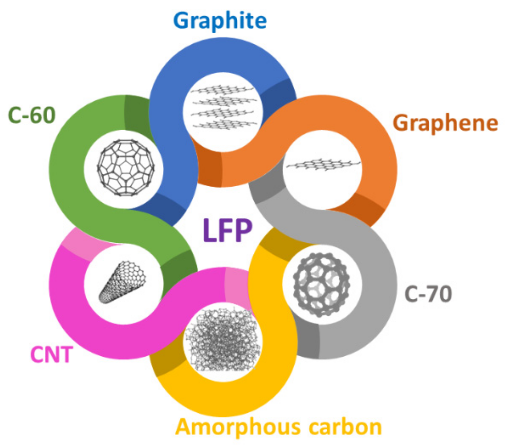
Carbon compounds are available in various structures and dimensions, including graphene, graphite, reduced graphene oxide (rGO), carbon nanofibers, and nanotubes each with its own set of physical and chemical characteristics, allowing for a wide range of options for stabilizing electrodes [17].
(iii)
Sources for Carbon materials are plentiful and inexpensive [17].
(iv)
The light weight and compatibility of carbon compounds ameliorate the electrode space utilization in LIBs [18].
Carbon is one of the highly suitable materials to stabilise LFP due to the above-mentioned points, which contribute to their practical adaptability [16]. Adding carbon is one of the most effective ways to alter the properties of LFP, boosting the material’s electron transport and performance rate. Carbon addition influences the electrode’s electrochemical performance, determined mainly by fabrication quality, including graphitization level, sorption capacity, and spread on the electrode surface [17]. Although carbon treatment may significantly increase the conductivity of LFP, too much carbon may impede Li+ ion transport. A carbon matrix of 1 to 10 nm thick is generally adequate to ensure a stable passage of lithium-ions across the electrodes [19]. Further, different chemical origins and structures of carbon exhibit different characteristics and thereby impacting the electrochemical and interfacial interactions.
This review paper highlights the present, future research tracks and hurdles of adding carbon structures into LFP (Figure 1). Some of the recent findings from 2015 to 2022 on carbon-LFP cathodes have been discussed. Recent literature has documented mostly on hydrothermal, electrospinning, electrophoretic deposition, template synthesis, and in-situ preparation of C-LFP. Further, the size, thickness, morphology, moisture level, porosity, and surface features of carbon impact the electrochemical performance of C-LFP. The effects of carbon addition to LFP, and its future research directions were also discussed.

2. Effects of Adding Carbon to LFP Cathodes

Carbon compounds, especially graphite, were introduced as electrodes from the 1960s in LIBs [20]. Because of the low equivalent weight and excellent intercalation chemistry of fluorinated graphite, Armand et al. identified them as ideal anode materials in 1977 [21]. Graphite is also a suitable material for battery cathodes because of its strong oxidizing power (electron affinity), mixed electron-ion conductivity, and structural stability. The type of carbon, production method, morphologies, particle size, coating thickness, additives, and surface functionalization all affect the capacity and performance of LFP-carbon batteries; this section discusses the recent developments and effects of carbon-LFP cathodes.

2.1. Carbon Sources

Carbon materials offer high electrical conductivity, thermal stability, and chemical stability in various electrolytes, from severely acidic to basic. The electrochemical performance of the C/LFP electrodes is determined by the carbon precursor, such as organic, inorganic, polymer, and biomass. The following section discusses the impact of various carbon sources on the electrochemical performance of LFP-C cathodes.

2.1.1. MOFs-Derived Carbon

Metal organic frameworks (MOFs) are porous periodic structures created by organic ligands and metal ions. MOFs have recently been employed as precursors for in-situ synthesis of MOF-derived carbon cathode materials, which has sparked researchers’ interest and gained popularity. MOF-derived carbon exhibits high porosity, tunable pore size, high surface area, excellent cycle life, and charge storage capacity [22]; they are frequently produced by the hydrothermal or solvothermal method and used as templates to make carbon materials. As a conductive buffer layer, a porous carbon framework produced from MOFs by calcination and post-annealing treatments benefits the homogeneous electroactive species distribution. Dopants such as F, B, Cl, S, and O may also be added to MOF-derived carbon to improve electronic conductivity, active sites, and defect reduction [22]. Simultaneous doping of heteroatoms into carbon nanomaterials increases their electrochemical activity, resulting in a stable reversible capacity. Lin et al. used Metal Organic Framework (MOF) to derive C-LFP cathodes with F and O co-doping via a solid sintering process [23]. At first, the Fe-MOF was prepared using a solvothermal self-assembly process and mixed, sintered with ammonium fluoride and ammonium dihydrogen phosphate. Finally, the prepared MOF-derived LFP was encapsulated in an O doped carbon matrix. Because of its greater sorption capacities and reduced Li transport obstacles, the dense carbon matrix becomes thermodynamically advantageous, supporting more reaction species and enhancing the diffusion rate and electron conductivity; this MOF-derived C-LFP had a remarkable specific capacity of 169.9 mAh g−1 at 0.1 C. Song et al. reported the use of Co2+–Co conversion reactions in cobalt MOF nanowire anodes and LFP cathodes. The Co MOF exhibited a high Li-ion storage capacity of 1100 mAh g−1 at 20 mA g−1 and stable cycling over 1000 cycles [24]. Despite some promising results, utilization and research of MOF-derived carbon cathode materials are currently in their early phases, owing to the repeatability of the same structures during synthesis.
Xu et al. presented two distinct methods for preparing carbon coated LFP cathodes, in which carbon was obtained from ZIF-8 MOF by carbonization and in-situ annealing; they reported that the LFP-carbon composites still retained the olivine structure with additional characteristics of mesoporous graphitic carbon [25]. Electron microscopy analysis show no relative structure between LFP and ZIF-derived carbon. However, the LFP@CZIF-8 sample has a core-shell structure. The in-situ prepared carbon-derived ZIF-derived carbon/LFP had pores of size ranging from 1.9 to 244 nm. The interconnected porous structure was advantageous for electrolyte wetting, lithium-ion diffusion (shortening the route of mass and charge transfer), charge transfer, and increased degree of freedom for volume change during charge-discharge cycles. Here, the Li-ion diffusion rate of ZIF-derived carbon/LFP 1.17 × 10⁻¹³ cm2 s−1 was 20 times higher than conventional LFP cathodes (6.7553 × 10⁻¹⁵ cm2 s−1). The fabricated cathode material delivered a discharge-specific capacity of 159.3 mAh g−1 at 0.1 C and discharge-specific energy of 141.7 mWh g−1 after 200 cycles at 5.0 C with 99% capacity retention [25]. MOF structures aid in the creation of carbon with high porosity and electrical conductivity, which can then be employed with LFP to improve Li+ ion diffusion and cycle life.

2.1.2. Biomass and Organic-Derived Carbon

Biomass-derived carbon has eco-friendliness and renewability. After multiple refining, acid, and heat treatments, the biomass waste is transformed into porous carbon materials. Previously, pyrolysis, chemical activation, solid state synthesis and thermal decomposition processes were performed to synthesis carbon from biomass waste. Porous structures such as hierarchical pores, 3D pores, and cross-linked pores are reported for biomass-derived carbon [26]. The presence of surface functional groups is relatively higher in biomass-derived carbon than chemically-derived carbon; these additional functional groups promote the adsorption of ions, electrolyte penetration, and their reactivity and, at times, lead to the formation of different compounds during the electrochemical reactions. In addition, different sources of biomass have different chemical components. For example, carbon-rich biomass contains significant amounts of nitrogen, oxygen, and hydrogen. The natural existence of nitrogen, boron, and hydrogen in biomass, which persists as heteroatoms after converting into carbon, boosts porosity, electrical conductivity, and ion absorption; as a result, the overall electrochemical performance can be improved [26]. Other elements that may be found in trace levels include phosphorus, silica, calcium, magnesium, sodium, and potassium. Some commonly used biomass sources are rice husk, coconut shell, wheat bran, vegetable wastes, spinach, groundnut shell, and nut’s shell. Among them, coconut shells have popularly been investigated as promising carbon sources. One recent example is the use of coconut shell-derived rGO composited with LFP using mechanical ultracentrifugation technique, where the rGO and LFP were prepared separately using pyrolysis and sol-gel technique and mixed via ultrasonication. Initially, the rGO solution was added to LFP nanoparticles mixed with n-butanol and ultrasonicated till the formation of a slurry. Post heat treatments at 80 °C for several hours, the rGO/LFP cathodes were obtained [27]. The LFP particles adhere firmly on both sides of rGO layers with increased surface area and reduced Li-ion diffusion path; this post-synthesis mixing protocol opens up opportunities in the future to explore other biomasses and mixing procedures. The study also suggests that sp2 hybridised surface carbon on LFP performed electrochemically better than sp3 hybridised carbon [27]. Another study showed that a significant number of defects created by nitrogen-doping in the sp2 carbon structure are advantageous for lithium transport at the interface [28]. Orange peel is another commonly used biomass to derive carbon. Recently, Carbon was extracted from orange peel using a mechanical activation process and coated on LFP. The orange peel-derived carbon-coated LFP was found to have homogeneous particle size and good electrical conductivity [29]. In general, chemical and physical activation processes are used for the surface functionalization of prepared carbons; each has its own benefits and drawbacks. Physical activation, particularly when utilizing steam, generates a lot of pyrolytic oil, although the yields are minimal. In comparison, the yield is greater in the chemical activation process, and little or no pyrolytic oil is produced. Similarly, in physical activation the particle size varies with temperature, but less aggregate formation is noted, whereas in chemical activation, the converse happens upon increases in temperature. Several considerations must be addressed while selecting a surfactant or activation reagent in an activation process. H3PO4, H2SO4, HNO3, ZnCl2, NaOH, KOH, H2O2, K2CO3, and CaCl2 are some of the activation agents used for carbon synthesis; it is also worth noting that the effects of different activation reagents on biomass vary. For example, it is widely assumed that oxygenated compounds favor activating impacts on biomass [30]. One method for determining whether or not new functional groups have arisen on the carbon surfaces is to do an FT-IR study. Cellulose, lignin, glucose, and citric acids were used as biomass sources for preparing carbon-coated LFP, as reported in previous reviews [30].
Most recently, sericin, a protein layer that silkworms use in the creation of silk, was used as a bio precursor for preparing carbon-coated LFP. Sericin powder was obtained from silk worms by degumming process, mixed with LFP, and heat treated at 500 °C for 3 h in Argon atmosphere to obtain nitrogen-doped carbon coated LFP (N-C@LFP). The sericin layer is rich in nitrogen and carbon, thus creating nitrogen-based functional groups on the surface of C-LFP. The excellent discharge capacity of 113.5 mAh g−1 with 1 wt% of N-C@LFP was observed, which was 20% higher than bare LFP. Further, the carbon derived from sericin was observed to be susceptible to the transport of Li-ions between the electrode and electrolyte. The Rct value of N-C@LFP was lower than bare LFP, accounting for increased electrical conductivity in N-C@LFP samples [26]. In a similar work, Gangaraju et al. employed an in-situ preparation of silk cocoon-derived carbon-LFP composites. At first, salts of Li, Fe and P were dissolved in ethanol and heat treated, followed by the addition of silk cocoon and microwave heating at 220 °C for 70 min and calcination at 700 °C in argon gas for 4 h. The prepared C-LFP composite had a discharge capacity of 140 mAh g−1 at 1 C and 98% capacity retention after 200 cycles [31].
Organic precursors have the benefits of inducing surface functional groups such as nitrogen, fluorine to the carbon structure. Organic groups with ring structure and aromatic groups have been reported to exhibit high graphitization levels, promoting electrical conductivity. Several organic precursors such as phytic acid, N-methylimidazole, Oleylamine, and butyl-3-methylimidazolium dicyanamide were used as organic precursors [32]. The method of preparing the carbon from these organic precursors and the parameters such as temperature, atmosphere and additives added during the preparation stage, influence the electrical conductivity, surface functional groups, porosity and additional properties of carbon. At high temperature (>700 °C) and in N2, Ar atmosphere, maximum carbon yield has been obtained. Porosity was induced by chemical activation and post synthesis thermal treatments. At times, porosity can be induced in-situ by the addition of chemical additives and surfactants, which has been previously discussed in other reviews. Table 1 provides a comparison between the different biomass sources of carbon, method of preparation and coating, functional groups on carbon, discharge capacity and other relative features of papers published from 2016 to 2022.

2.1.3. Polymer-Derived Carbon

Polymers-derived carbon (PDC) has different surface functional groups depending on the base monomer. The conversion of polymers to carbon is not always perfect. Short-chain polymers break down rapidly in organic electrolytes, limiting battery cycle life. Long-chain polymers are stable and have negligible solubility in electrolytes. Polymers such as polypyrrole, polythiophene, PEDOT, polyvinyl pyrrolidone, and polyaniline are used to build porous carbon. Conducting polymers are more suited for obtaining carbon for its use in battery applications. In particular, highly graphitized carbons are produced when functionalized heterocyclic or ring-forming compounds are used in pyrolysis. Nien et al. compared the carbonization behavior of four different polymers, namely poly(ethylene oxide) (PEO), polybutadiene (PB), polystyrene (PS), and styrene-butadiene-styrene (SBS). The pyrolysis process was employed, and vinyl compounds (PS) were observed to form scissions. Main chain scissions develop without the formation of volatile chemicals during the pyrolysis of PS, and the carbonization process of unsaturated bonds and aromatic rings promotes the formation of graphite. The authors revealed that PS is the best suitable polymer for developing a fine particle size LiFePO4/C composite and an evenly coated carbon conductive layer with improved electrochemical performance. The main advantages of using PS as a polymer additive include coordinated LiFePO4 crystallization and PS pyrolysis [34].
Depending on the process conditions, PDC has diverse morphologies and is commonly synthesised by template or direct synthesis. Phase separation and heat treatment are used to create porous structures in polymers. Various inorganic, organic, and hybrid templates are employed in template synthesis. Fischer et al. used block copolymer (300 mg of Pi-b-PEO) and homopolymer (500 mg of PS) as templating and extra carbon sourcing agents, respectively, for preparing LFP-C composites using template synthesis. The block copolymer (BCP) acted as a structure-directing agent and aided in forming stable molecular complexes. Furthermore, the homopolymer does not interact with BCP, thus increasing the electrical conductivity without forming larger aggregates. LFP/C composites based on BCP exhibit high cyclability, with over 92% capacity retention after 1000 cycles at 1 C and an average Coulombic efficiency of 99.5% [19]; it is essential to choose polymers rich in carbon for higher carbon extraction. Polyacetylene and its derivatives are rich in carbon and available in nature (plants and fungi) [35]. Poly(carborane-siloxane-arylacetylene), poly(1-(4-trimethylsilylphenyl)-2-phenylacetylene), and polyacetylene derivatives may also be investigated in the future for carbon extraction and use in batteries [36]. Anna et al. used polydopamine-derived carbon, which exhibited higher ionic diffusion coefficients due to the thinner coatings (~6.5 nm) and thereby facilitating the stable phases without either much nucleation or formation of new phases. The overlap of current peaks was observed during galvanostatic cycling for thicker carbon coatings on LFP, which was neither a kinetic nor diffusion type of intercalation and was thus attributed to the development of new phases during the charge-discharge process [37]. Different morphologies of carbon can be obtained with different polymer sources and process conditions. Porous structures are highly beneficial in improving the cyclic performance due to the creation of excessive surface area of ion insertion and disinsertion, especially in the case of graphene. To summarise, there is no standard morphology for PDC, and new morphologies emerge on a monthly basis. Specifically, an LFP cathode with a conductive framework and porosity, a high degree of graphitization, thinner coating (2 to 20 nm), and surface functional groups (N, P, B) can all contribute to improved electrochemical performance. The charge transfer resistance reduces as the degree of graphitization increases, and thereby promoting the electrical conductivity; it is critical to fine-tune the coating thickness and graphitization level to properly protect the electrodes from electrolytes while allowing ions to pass between the electrodes.

2.2. Dimensions at Nanoscale

The tendency of a material’s characteristics to vary rapidly at the nanoscale (below around 100 nanometers) is vital to recognize; these unforeseen changes are known as “quantum effects”, which can be seen in low-dimensional structures. Due to these quantum effects, the nanomaterials exhibit higher electrical conductivity, elasticity, mechanical strength, and stronger reactivity.

2.2.1. One Dimensional (1D) C-LFP

Carbon nanotubes (CNTs), a one dimensional carbon nanomaterial, with diameters ranging from 0.6 to 50 nm, commonly formed from a thin sheet of pure graphite, have excellent features of strength, thermal, and electrical conductivity that have been employed in the field of energy storage for the past two decades. The electrons navigate easily in 1D carbon materials. The increased surface area of multiple carbon coating, sandwich, mesoporous, and hollow structures leads to improved ion mobility. Carbon materials, coating techniques, and associated electrochemical performances have all been explored in previous papers. As a reason, this section concentrates on the influence of key factors in determining LFP’s electro-chemical performance.

Effects of Synthesis, Particle Size, Diffusion Path and Bonding on 1D C-LFP

The effect of particle size, shape, diffusion path, and velocity has been explored here, as well as the most modern and widely used methodologies. Firstly, the limited conductivity of LFP causes strong polarisation under significant charging rate conditions, causing a drop in overall capacity. In order to overcome this main issue and for making high-quality LFP cathodes, researchers used a variety of synthesis procedures [38]. Hydrothermal synthesis of LFP with carbon coating through heat treatment has been rejuvenated for fabricating the cathode in Li-based batteries because of its low cost, simplicity, and familiarity. One of the recent examples is the work done by Kanagaraj et al., which discusses the preparation of multiwall carbon nanotubes (MWCNT) coated LFP using the hydrothermal method combined with tape coating methodology, as shown in the Figure 2a. The densely packed carbon-coated LFP exhibited excellent Li-ion storage capacity of up to 4.3 V. On the other hand, the half-cell study (Figure 2b) failed to yield adequate capacity values, which might be attributed to the increased crystallite size (51.07 nm) and shape (Capsule-like) of the synthesized LFP, thereby restricting the ionic mobility and conduction of electrons [39].
The size distribution, shape, temperature, and thickness of the carbon layer influence the production of the secondary surface phase (Fe2P) in LFP [38]. In general, temperature-assisted carbon coatings entails two processes (i) Reduction of carbon to gas (ii) Formation of secondary phases Fe2P and LiPO4. The carbon reduction by smaller particles (less than 20 nm) of LFP may result in improved reactivity because of the increased surface area. In a recent study, it was found that 60 nm thick carbon coating on LFP necessitates high temperature for formation of secondary phases, whereas 2 nm thick carbon coating can form Fe2P phase at low temperature [42]; this study suggests that these additional Fe2P phases facilitate improvements in the electrochemical performance because of its active species. MV Reddy et al. and group designed uniform carbon (30 to 40 nm) coated LFP nanoplates (Figure 2c–e) cathodes for LIBs and identified the shorter Li+ diffusion pathway because of the reduced size and plate morphology [40]. The same group also identified the increase in volume and linear expansion coefficient of LFP in accordance with increased temperature (777 °C). Figure 2f,g shows the volume expansion of LFP with an increase in temperature, simulated using molecular dynamics. Precisely, the Fe-Fe distance in LFP increases upon increasing the temperature.
Secondly, the effect of carbon-coated LFP on Li-ion intercalation, diffusion pathway is a recent topic of discussion. Le et al. identified that CNTs prepared via a hydrothermal route would not affect the Li-LFP intercalation-deintercalation routes but ameliorate the electronic conductivity and ion diffusion velocity [43]. In terms of endeavoring a good perception of LFP intercalation mechanisms, Lu et al. and co-workers reported an X-ray microscopic investigation on Li0.5FePO4 nano- and bulk structures. Using multiple spectroscopic, microscopic tools, and DFT calculations, they found a drastic decline in Li concentration from surface to bulk of Li-rich particles. In contrast, there was no change in the concentration of Li for the Li deficient particles, which reveals the surface sluggish lithiation behavior of Li-rich particles transferred from Li deficient to Li rich bulk particles as shown in Figure 3a,b. Li-rich particles are mapped in red, whereas Li-poor particles are marked in green. Further, the X-ray absorption near edge structure (XANES), photoemission electron microscopy (PEEM), and Scanning transmission X-ray microscopy (STXM) of Li rich and deficient particles obtained in the bulk, surface, their lithiated, delithiated spectral profiles are shown in Figure 3c. The lithiation and movement of ions in the [010] transport plane change slightly since the [010] plane is the fastest Li diffusion pathway in LFP [44]. From Figure 3d, both Li rich and deficient particles spread evenly avoiding clumps, which might be ascribed to interparticle diffusion of ions.
Finally, the bonding involving a heat-injected coating is significantly stronger than mechanical linkages. Ventrapragada et al. developed a CNT-coated LFP cathode via sustainable spray coating without any surfactants. Carboxymethylcellulose, rubber, graphite and carbon super P were taken as source materials to derive C-LFP cathode, which boosted the cell performance by enhancing the energy density (~460 Wh Kg−1) [45].
Achieving the optimal diffusion of CNTs in LFP is a happening concern. Compared to standard CNT sludge, LFP coupled with a conductive framework made of agglomerated CNT and PVDF mixtures had better device performance. Zhang et al. used PVDF for enhancing the dispersibility of CNT in the N-methyl pyrrolidone/LFP mixture, which was stable even after 48 h as shown in Figure 4c,d. The corresponding TEM images of the agglomerated CNT were shown in Figure 4a with the size distribution spectra (Figure 4b). The inclusion of PVDF reduced the diameter of CNT agglomerates and enhanced the miscibility of CNTs, which was inferred from Figure 4b. Further adding PVDF, the mixture’s viscosity (CNT-PVDF) increased to 37 mPa S−1 from 35 mPa S−1, enhancing the shear force within the solvent and CNT; this leads to the development of the CNT dispersion stability even at extreme disturbances [46].

Effects of Fabrication Method, Additives, and Surfactant on 1D C/LFP

1D Carbon nanofibers (CNF) with a high specific surface area have an extensively carbonized framework with a short d spacing ((d002) > 0.335 nm) and considerable crystal thickness, allowing for superior mechanical characteristics. Further, multifunctional additives change the design, morphology, and physical traits of CNFs, encompassing a wide range of properties required for electrochemical application. Fongy et al. and group produced CNF and used a non-ionic surfactant to blend them into a slurry of LFP cathode; they estimated the influence of CNF on the ionic and electronic conductivities of LFP and identified that the addition of CNF has enhanced the capacity; they analyzed the impact of CNF on LFP’s electron transfer conductivities and reported that adding CNF boosted the capacity; they further asserted that the porosity of LFP-CNF structure has contributed to improved electronic wiring properties and diffusion of Li+ ions by generating multiple 1D channels [47]. Adepoju et al. found a similar result, demonstrating a higher C-rate (>5 C) when CNF was added to the LFP cathode. The slurry was made up of LFP, vapor-grown CNF, carbon black, and PVDF, which were combined in an 80:10:10 ratio with the assistance of the N-methyl 2-pyrrolidone solvent. In comparison to the virgin LFP electrode (140 mAh g−1), the altered LFP-CNF cathode has a more extended voltage as well as operational threshold (30 C) and produces a greater discharge capacity of 150 mAh g−1 (Figure 5a). The enhanced electrochemical performance achieved by incorporating CNFs notably reduces the solution viscosity of the pores. Hence, it improves the diffusion of ions across the CNF combined cathode, which can be elucidated to the immense current capacity. Having a larger peak current, the CV of the LFP/CNF electrode has the finest harmonious and sharper curve pattern of the oxidation (0.24 V) and reduction potentials (0.39 V). As shown in the CV (Figure 5b) the highly oriented peaks and larger potential differences were attributed to the addition of CNF, which boosted the ion diffusion with reduced resistance between the particles [48].
The electrochemical activity of the cathode is influenced by C and LFP production methods, based on scientific observations. Three practices were mostly reported in the past for preparing LFP-carbon composites, namely,
(i)
Mixing of carbon and LFP, post synthesis;
(ii)
Depositing or coating carbon structures over LFP via solution/vapor phase;
(iii)
In-situ co-formation of LFP carbon composite.
Though hydrothermal synthesis was simple and familiar, electrospinning, electrophoretic deposition, and template synthesis processes proved to be promising for manufacturing C-LFP cathodes since many operational parameters may be adjusted in line with the material’s architecture and conductivity. Hagberg et al. developed CNF structures as a strengthening material and current collector for LFP cathode using electrophoretic deposition (Figure 5c) with a bath mixture of carbon black, I2, Triton-X and PVDF in acetone. The I2 triggers the release of H+ ions during the supply of electric current, promoting the build-up of positive charges, which are then driven towards the CNF, producing a thin layer coating. In addition, Triton-X was employed as an additive to prevent the formation of clumps. However, high resolution SEM images revealed a few uneven and dense coating, lowering mechanical characteristics, electrochemical contact, and capacity. As illustrated in the SEM image of Figure 5d, altering the inter-electrode spacing between the Pt counter electrode and the CNF culminated in a homogeneous and consistent deposition. The fabricated cathode was crucial in achieving a capacity of 110 mAhg−1, with a decent capacity retention of 0.75 and a coulombic efficiency of ~99%. After multiple charge-discharge cycles, the electrophoretic coating continued to persist without significant wear [49]. Similarly, Cao et al. used PVP-derived single pot electrospinning method for synthesizing in-situ CNF (010) faced LFP hybrid cathode. Interestingly, 98.2% of the initial capacity (152 mAh g−1) was retained after 500 cycles, which was attributed to the porous cathode framework and fast ion transport [50].
Recently, in situ soft template synthesis of LFP on 1D carbon nanosheets (CNSs) and CNTs have been reported to perform synergistic outcome due to the structural framework facilitating both electron transfer outside the circuit and ion transfer inside the electrolyte with high mobility, thus improving the overall electrochemical performance. Further, the dual nanosheet and nanotube network improves the electron conduction and eliminates the formation of aggregates during continuous cycles [51].

Effects of Surface Functionalization on 1D C-LFP

Surface properties and ion conduction of the CNF can be adjusted via the functionalization of –OH, C=O, –COOH groups into the active sites of the CNF. Exterior functional groups primarily function as binding spots and thereby crosslinking or interlinking the molecules during the fabrication and electrochemical testing processes. Activating structures such as CNT, graphene, Mxene, and Prussian blue analogues have been decorated over the CNF-LFP cathodes to widen the pores and increase the surface roughness; this will lead to enhanced ion kinetics favoring sufficient capacity and extended shelf life of the cell. Increasing the reactive spots and changing the hydration tendency of the carbon frameworks on the exterior portion of CNF might increase sorption capacity. Carbon sources like CH4 and C2H2 have typically been utilized to mount CNTs onto CNFs while using vapor deposition methods. The morphological traits of the coated carbon can be altered through catalysts. One such example is the synthesis of CNFs employing Pd and Fe-based catalysts. Similarly, Au nanoparticles are used to boost the interfacial ion transport and thermal properties of precoated CNF-LFP composites. The significant reason for the distribution of Au into the carbon atoms is to activate the resonance of LFP, resulting in increased convection throughout the electrode interface. Secondly, due to the removal of unequal electron symmetries, the Au-loaded CNF-LFP exhibits increased electrical mobility with low heat production and, consequently, high thermal resistance [52].

2.2.2. Two-Dimensional (2D) C-LFP

As discussed in the previous section, owing to their excellent electrical conductivity, 1D carbon nanostructures have been routinely integrated into LFP to increase their electrochemical usefulness. In recent decades, the Monolayer 2D material, graphene (G), invented in 2004 with Sp2 hybridized structure, has been prominent as a mixture or addition to LFP due to its high electronic conductance (~2 × 105 cm2 V−1 S−1), thermal conductance (~5 × 10³ W m−1 K−1), high surface to volume ratio, and excellent mechanical properties; it is widely assumed that graphene can make quite effective structures for cathodes than ordinary carbon additives such as carbon black.

Effects of Fabrication Methods and Additives

The easiest and the most direct way to produce LFP-G composites is to manually combine the two materials that are synthesized separately. However, significant improvement in the electrochemical performances were not observed, resulting in decrease in electron conduction. The decrease in electronic conductivity in such circumstances might be due to inadequate interaction among graphene and LFP. Considering this limitation, Yang et al. developed LFP-G composites using a self-assembly approach based on an electrostatic interplay between LFP and graphene oxide (GO) sheets, resulting in the reduction of GO to G wrapped LFP structures. According to the authors, selective graphene wrapping over LFP can keep ion and electron transport stable within the LFP-G composite, whereas complete wrapping separates LFP from the electrolyte species and thus impedes ion permeation to a certain extent, resulting in higher charge transfer resistance [53,54].
In situ growth of LFP on pre-produced G has promoted the contact between LFP-G, dispersion strength and reduced aggregate formations, resulting in improved ion diffusion. Wang et al. prepared LFP-G composite via in-situ approach using Li2CO3 and NH4H2PO4 as precursors. He reported that the concentration of G greater than 5 wt% was additives, which generated notable improvements in the discharge capacity [55]. Yang et al. synthesized homogeneously distributed 2D graphene on 3D LFP porous structure via sol gel technique, with an evolution of xerogel framework comprising GO, LiH2PO4 and additives, which gets reduced into G decorated 3D LFP [56]. Another interesting work by Kim et al. and co-workers showcased the separate preparation of GO/FePO4 and subsequent integration of Li+ via the lithiation process holding benefits such as (i) minimal oxidation of Fe2+ and (ii) high contact between LFP and G. The developed platelet-like G structure had minimal surface defects allowing straightforward anchoring of Li+, which leads to faster ion transfer as Li+ ions are available on the surface [57].
Another interesting method is powder extrusion for manufacturing granular LFP-C particles on a polymer matrix as shown in Figure 6a. The extrusion method has several advantages compared to conventional tape casting or compaction techniques. Extrusion offers binder-free and self-standing electrodes with adjustable thickness and areal capacity. Additionally, the morphology preservation after extrusion is outstanding due to the feedstock’s constant pseudoplastic characteristic. Carmen et al. employed an inert extrusion set-up for binding and sintering to achieve a durable carbon coating on LFP and to reduce Fe oxidation [58]. The employed parameters such as loading volume and sintering temperature to prepare ~500 μm thick electrodes were 55 vol% and 650 °C respectively. The areal capacity of the extruded electrode was 13.7 mAh cm−2; this finding opens the door for the generation of eco-friendly Li batteries. However, the extrusion process is not suitable for producing electrodes below 20 µm. Cao et al. demonstrated the use of LFP cathodes with glucose-derived carbon and graphene microspheres prepared via solvothermal method having a diameter of 5 to 12 µm [59]. The group used Phytic acid as a source of phosphorus, which also aided in the formation of spherical structures. Figure 6b,c shows the assembled carbon-LFP-graphene composites via solvothermal synthesis. The micro spherical carbon structures contributed to the high-rate capability of 137.3 mAh g−1 at 1 C and the discharge capacity of 163.7 mAh g−1 at 0.1 C. Similarly, morphology-tuned cathodes have the modified electrode interfacial characteristics. For instance, Bao et al. prepared morphology controllable LFP structures by varying the KOH concentration and pH in the hydrothermal method [60]. At first, the self-assembled LFP microspheres were formed, and upon increasing the KOH concentration, the spheres transformed into spindle, needle, and flower shapes, respectively as depicted in Figure 6d. The combined impact of pH and adsorbed K+ ions on the surface might underlie the crystal formation process. The OH anions reflect the increased pH value controlling the multilevel shapes; however, under moderate KOH concentrations, the K+ ions contribute to the monodispersed LFP. The LFP flowers exhibited the highest reversible capacity ~145 mAh g−1 with 98% capacity retention and stable cycles.

Effects of Particle Size, Thickness, and Surface Functionalities

Dual coating or compositing of carbon-LFP-G (G-Graphene) structures can improve the electrochemical performance as the overall conductive framework and structural rigidity increases. However, unevenly distributed carbon over LFP or multiple disordered deposition of G/carbon layers may reduce the effectiveness of complete electrode functionality. Further the amount of G composited with LFP has a significant effect on the electrochemical performance. Substantial incorporation of G into LFP has the possibilities of reducing the volumetric energy density due to poor dispersion of G, attributed to large G to smaller LFP ratio and reduces the tap density. The optimal concentration of G in LFP, according to several study groups, is between 2 to 25 wt% [61]. However, it appears that there is no one standard value for comparing these optimal carbon content levels. Considering this, most research suggests that a small proportion and adequate distribution of G are critical, enabling its use as a conduction enhancer in a cell.
The thickness of rGO layer has an impact on the electrochemical performance. Multiple stacking of folded G/rGO layers might result in reduced dispersion of G into LFP and creates aggregates. On the other hand, unfolded stacking of G layers can facilitate the migration of Li+ ions evenly from both the electrode direction, decreasing the polarization, and charge transfer resistance [62]. Though, G/rGO/carbon additives improve electron conduction, their excessive usage may hinder the passage of Li+ ions. Alternatively, highly porous carbon structures have adequate spacing for the migration of Li+ ions between LFP and the active anode material [63]. Considering this, Ha et al. introduced chemically activated G into LFP with the generation of pores during the activation process aided by KOH. Here, KOH gets reduced to metallic K during the activation process, whereas carbon atoms in G undergo oxidation producing carbonates, resulting in the formation of numerous pores on the top of G [64].
Extrusion method can be utilized to change the electrode thickness (from over 20 µm to a few µm), but recent researchers suggest that the carbon thickness must be kept below 20 µm for high electrochemical performance. Yi Cui and group demonstrated a new technique for producing Li-rGO anode below 20 µm thickness by employing a calendaring process for rGO preparation followed by contact loading of molten Li, as shown in Figure 7a [65]. The same can be possibly used for preparing LFP-carbon cathodes. Similarly, Yang et al. and colleagues used a different technique for fabricating LFP nanosheets of ~15 nm thickness. The group used ultrasonic waves to exfoliate LFP (Figure 7b) and subsequently self-assembled with rGO via amido bonds. Here, the large percentage of (010) facets accessible to LFP reduces the distance of the diffusion path, improving the transport rate of Li-ions. Furthermore, sintering the self-assembled rGO for adhering it into LFP enables an efficient conductive matrix, facilitating electron transmission. The ultrathin diffusion path with conductive rGO matrix enabled a high-rate discharge of 102 mAh g−1 at 30 C with 93.4% capacity retention after 500 cycles [66].
Owing to huge surface area and enhanced electrical conduction, 2D materials have become an effective battery electrode. In this regard, next to graphene, Ti3C2Tx and Mxene structures have received the most particular attention for functionalizing with carbon-coated LFP. Furthermore, Mxene’s surface reactive groups promote its solubility and dissolution rate and thereby making it simpler to integrate with additional compounds.

2.2.3. 3D Carbon LFP Composite

As previously stated, graphene has a large surface area as well as a high electrical conductivity. However stacking of multiple layers and porosity are crucial factors to be considered while designing LFP-G electrodes. Many benefits, such as systematic porosity pathways, excellent electronic conductance, and outstanding mechanical strength, may be found in the 3D carbon nanostructure due to structural interconnections. More research in the realm of 3D C-LFP is required for optimizing the performance characteristics. At present, in situ template synthesis and polymerization reactions aid in fabricating 3D C/LFP. Weng et al. and colleagues used a one-step condensation polymerisation reaction to prepare the precursor, hydroquinone-formaldehyde resin (HFR). Then, NH4H2PO4, Fe(NO3)3, and Li(OH)2 were then mixed with the HFR and subsequently carbonized at 600 °C for obtaining LFP/3D carbon structures. Next, they synthesized 3D carbon/LFP in-situ using glucose as a carbon source for comparison. Due to carbonization and polymerization, a solid 3D structure with higher number of internal pores were reported; these internal pores boost the Li+ ion migration and the electrochemical conversion efficiency. The 3D solid sourced from glucose and HFR polymerization has resulted in the discharge capacity of 151.1 mAh g−1 and 169.3 mAh g−1 at 0.1 C, due to the interconnected porous structure [67]. Porous 3D LFP-G composites were found to increase the conductivity and reversible capacity even at varied current densities [68].
Xing et al. fabricated a 3D LFP/C conductive, porous, core-shell structure with 2D carbon thin coating (~2 nm) using template synthesis, exhibiting high ionic and electrical conductivities. The discharge capacity of LFP/C was 166 mAh g−1 at 0.1 C with 98% active material utilization, while the mass loading of active material was 80%. The 3D LFP/C structure increased the interfacial contact between the electrolyte and electrode, allowing for better ionic diffusion and increased electrical conductivity. According to the recorded CV curves and Randles–Sevcik Equation (equation to find peak current in the diffusion-limited process), the 3D LFP/C has a linear relationship (i.e., Ip, the peak current, is proportional to the square root of scan rate) with a diffusion coefficient of 1 × 10⁻¹⁰ cm2 s−1. [69]. In another study, LFP/C nanowires with a 3D nano framework were synthesized using a controllable self-assembly process, where amylose was used as one of the precursors. Amylose has a unique spiral structure with short branches serving as a carbon source and a self-assembly stimulator of other precursors along its core axis. The amorphous carbon from the short chains connects the co-axis 1D LiFePO4/C nanowires to the intricate 3D nano-framework structure [70]. In a different way, pechini-assisted polyol synthesis and electrospinning were used to prepare 3D LFP/C with cauliflower-like morphology. The surface examination of the produced composites indicated a homogenous coverage of carbon nonwoven nanofibers and uniform distribution of crystals. The 3D LFP/C showed an excellent discharge capacity of 156 mAh g−1 at C/25 discharging rate [71].
Recently, composite of CNT has been used with a 3D LFP cathode in the shape of nanoribbons via crosslinking of bisphosphonate (risedronic acid) by insitu hydrothermal method. The prepared 3D structure was found to have size less than 300 nm with perfect olivine structure, promoting the cell performance to 162.2 mAh g−1 beyond 800 cycles; this was ascribed to the size effect and coverage of 3D LFP with porous CNT [72]. Chen et al. developed a fusion of 3D networks consisting of LFP-CNT doped with nitrogen that combines the benefits of nanotubes and nitrogen doping sourced from PVP. Additionally, a simple ball milling synthesis method followed by sintering was used to produce nitrogen doped LFP-CNT composite. The calcination temperatures (550 °C, 650 °C, 750 °C) and duration were varied for obtaining the different LFP-CNT samples. The polarization losses and impedance have been reduced significantly owing to maximum capacity ~100 mAh g−1 with 95.7% capacity preservation for LFP calcined at 750 °C for 5 h [73]. In another work, high temperature synthesis was used to prepare 3D CNT-LFP using polyethylene glycol, as shown in Figure 8a. PEG acted as a conductive additive, binder and dispersant enabling high reversible capacity and ion mobility [74]. Lin et al. used Metal Organic Framework (MOF) to derive C-LFP cathodes with F and O co-doping via a solid sintering process [23]. The experimental process is shown in Figure 8b. At first, the Fe-MOF was prepared using a solvothermal self-assembly process and mixed, sintered with ammonium fluoride and ammonium dihydrogen phosphate. Finally, the prepared MOF-derived LFP was encapsulated in an O doped carbon matrix. Because of its greater sorption capacities and reduced Li transport obstacles, the dense carbon matrix becomes thermodynamically advantageous, supporting more reaction species and enhancing the diffusion rate and electron conductivity. The MOF-derived C-LFP had a remarkable specific capacity of 169.9 mAh g−1 at 0.1 C.
Qian et al. reported the formation of macro-mesoporous 3D bicontinuous LFP/C nanocomposites via the microwave-assisted solvothermal method with sucrose as a carbon source. The LFP/C composite showed excellent cycling stability with 87% capacity retention after 1000 cycles at 2 C charge-discharge rate and a discharge capacity of 129 mAh g−1 at 2 C. The rapid synthesis method favored forming several 3D macropores, which promote Li+ ions diffusion, and the mesopores being an active reaction site enhances the cycle life [75]. Carbon coating improves electrical conductivity with Fe3+ to Fe2+ redox transition and increases the polarization. Researchers from National Taipei University, Taiwan, recently reported the high-performance 3D mesoporous carbon encapsulated LFP, delivering a specific capacity of 184.8 mA h g−1, higher than the theoretical capacity of LFP (170 mAh g−1). After 1000 cycles, at a higher current rate of 10 C, the 3D LFP/C reveals an excellent discharge capacity of 120 mA h g−1 with 96.7% capacity retention [76].
Table 2 shows the preparation methods and performance for various carbon sources for C-LFP. From Table 2, it can be observed that the specific capacity ranged from 120 mA h g−1 to 165 mA hg−1. One of the works using MWCNT/LFP reported 195.2 mA h g−1 and hydrothermal, solvothermal, carbothermal and in-situ synthesis are mostly used. Microwave-assisted synthesis resulted in a decent capacity of 133.6 mAh g−1.

3. Effects of Electrolyte in Performance of C-LFP

Electrolyte type has a significant influence on LIBs performance. Solid-state electrolytes, especially polymer electrolytes popularized by Armand et al. are safer, sustainable, and hold high energy densities [122,123,124,125,126,127]. Perhaps, liquid electrolytes that are electrochemically, mechanically, and thermally stable, paired with a polymer/ceramic separator, could help until solid electrolytes become commercially viable. Armand et al. developed salts such as LiTFSI, TFSI, LiFPFSI and DFTFSI and polymers such as polyethylene oxide (PEO), pentaerythritol tetraacrylate (PETEA) for solid polymer electrolytes (SPE) [14]. Nanosized carbon, Si, and alumina fillers have been shown to increase the ionic conduction of SPE with the conductance augmentation being more beneficial for smaller nanofillers. The clumping of fillers in SE, on the other hand, inhibits ionic charge transport enhancement. Other challenges such as formation of Li dendrites, unstable electrochemical window, and conductivity concerned with SPE, are recapturing to be optimized by the researchers. Integration of ionic liquids into the polymer electrolytes has enhanced the conductivity. All solid-state LIBs could be the future version of rechargeable batteries, according to studies published in the previous few years.

4. Conclusions and Prospects

The evolution of LIBs was influenced by research on LFP since this compound has considerably increased the reliability, safety, and sustainability. However, because of the reduced work potential (3.1 V), low tap density, and limited ionic conductivity, research on substantial materials and cell fabrication optimizations are essential. Carbon layer thickness, surface area, porosity, and surface functionalities have all been proven in the previous literature, indicating the viability of rapid charging in the foreseeable. Particularly, in the recent years, doping of graphene, Mxene, and MOFs with porous carbon have resulted in the improved working potential and ion transport. The incorporation of conductive additives with high specific surface area has increased the conductivity of C/LFP.
Utilizing in situ, in operando characterization tools for real time detection and analysis of cell performance is recommended. Modern advancements in simulation tools, machine learning, and data science could possibly help for optimizing the electrode materials in LIBs. Moreover, future batteries are expected to be fully solid state considering the safety, energy density, and sustainability. In the near future, data science and artificial neural networks will make the process of selecting acceptable and potential solid-state electrolytes, electrodes, and cell components quicker by lowering experimental expense and time; it is impossible to predict which of the foregoing multiple alternatives will be the victor for subsequent generations of LFP based LIBs. Overall, with suitable modification, the truly excellent C-LFP is expected to bring a wide range of benefits to the energy storage sector in the forthcoming years.

Author Contributions

B.R.: Conceptualization, Formal analysis, Writing—original draft; S.S.: Formal analysis, writing—review and editing; V.C.: Technical discussion, revising the manuscript critically for important intellectual content; M.V.R.: Conceptualization, Writing—review and editing, technical discussion, revising the manuscript critically for important intellectual content; S.R.: Conceptualization, Technical discussion, review, and editing; K.Z.: Conceptualization, Technical discussion, review and editing. All authors have read and agreed to the published version of the manuscript.

Funding

This research received no external funding.

Institutional Review Board Statement

Not applicable for studies not involving humans or animals.

Informed Consent Statement

Not applicable for studies not involving humans.

Data Availability Statement

Not applicable.

Acknowledgments

BR acknowledges SINGA (SING-2021-02-0819) award, offered by Institute of Materials Research and Engineering (IMRE), Agency for Science, Technology and Research (A*STAR), #08-03, 2 Fusionopolis Way, Innovis, Singapore.

Conflicts of Interest

The authors declare no conflict of interest.

References

  1. Mohamed, N.; Allam, N.K. Recent Advances in the Design of Cathode Materials for Li-Ion Batteries. RSC Adv. 2020, 10, 21662–21685. [Google Scholar] [CrossRef] [PubMed]
  2. Chikkannanavar, S.B.; Bernardi, D.M.; Liu, L. A Review of Blended Cathode Materials for Use in Li-Ion Batteries. J. Power Source 2014, 248, 91–100. [Google Scholar] [CrossRef]
  3. Gong, Z.; Yang, Y. Recent Advances in the Research of Polyanion-Type Cathode Materials for Li-Ion Batteries. Energy Environ. Sci. 2011, 4, 3223–3242. [Google Scholar] [CrossRef]
  4. Lithium Iron Phosphate—The Ideal Chemistry for UPS Batteries. Available online: https://datacenterfrontier.com/lithium-iron-phosphate-ups-batteries/ (accessed on 15 July 2022).
  5. Padhi, A.K.; Nanjundaswamy, K.S.; Goodenough, J.B. Phospho-olivines as Positive-Electrode Materials for Rechargeable Lithium Batteries. J. Electrochem. Soc. 1997, 144, 1188–1194. [Google Scholar] [CrossRef]
  6. Manthiram, A.; Goodenough, J.B. Lithium Insertion into Fe2(MO4)3 Frameworks: Comparison of M = W with M = Mo. J. Solid State Chem. 1987, 71, 349–360. [Google Scholar] [CrossRef]
  7. Preger, Y.; Barkholtz, H.M.; Fresquez, A.; Campbell, D.L.; Juba, B.W.; Romàn-Kustas, J.; Ferreira, S.R.; Chalamala, B. Degradation of Commercial Lithium-Ion Cells as a Function of Chemistry and Cycling Conditions. J. Electrochem. Soc. 2020, 167, 120532. [Google Scholar] [CrossRef]
  8. [Battery+] Elon Musk Wants LFP Batteries for Tesla. Here’s Why Korean Battery Trio Shouldn’t Produce Them. Available online: https://www.koreaherald.com/view.php?ud=20211114000037&kr=1 (accessed on 15 July 2022).
  9. List of Elements of the Periodic Table—Sorted by Abundance in Earth’s Crust. Available online: https://www.science.co.il/elements/?s=Earth (accessed on 30 August 2022).
  10. Lu, J.; Tian, X.; Zhou, Y.; Zhu, Y.; Tang, Z.; Ma, B.; Wu, G.; Jiang, T.; Tu, X.; Chen, G.Z. A Novel “Holey-LFP/Graphene/Holey-LFP” Sandwich Nanostructure with Significantly Improved Rate Capability for Lithium Storage. Electrochim. Acta 2019, 320, 134566. [Google Scholar] [CrossRef]
  11. Ramasubramanian, B.; Reddy, M.V.; Zaghib, K.; Armand, M.; Ramakrishna, S. Growth Mechanism of Micro/Nano Metal Dendrites and Cumulative Strategies for Countering Its Impacts in Metal Ion Batteries: A Review. Nanomaterials 2021, 11, 2476. [Google Scholar] [CrossRef]
  12. Wu, H.; Liu, Q.; Guo, S. Composites of Graphene and LiFePO4 as Cathode Materials for Lithium-Ion Battery: A Mini-Review. Nanomicro Lett. 2014, 6, 316–326. [Google Scholar] [CrossRef]
  13. Balo, L.; Gupta, H.; Singh, S.K.; Singh, V.K.; Tripathi, A.K.; Srivastava, N.; Tiwari, R.K.; Mishra, R.; Meghnani, D.; Singh, R.K. Development of Gel Polymer Electrolyte Based on LiTFSI and EMIMFSI for Application in Rechargeable Lithium Metal Battery with GO-LFP and NCA Cathodes. J. Solid State Electrochem. 2019, 23, 2507–2518. [Google Scholar] [CrossRef]
  14. Chen, Z.; Zhang, W.; Yang, Z. A Review on Cathode Materials for Advanced Lithium Ion Batteries: Microstructure Designs and Performance Regulations. Nanotechnology 2019, 31, 012001. [Google Scholar] [CrossRef] [PubMed]
  15. Kumar, K.K.; Brindha, R.; Nandhini, M.; Selvam, M.; Saminathan, K.; Sakthipandi, K. Water-Suspended Graphene as Electrolyte Additive in Zinc-Air Alkaline Battery System. Ionics 2019, 25, 1699–1706. [Google Scholar] [CrossRef]
  16. Liu, Y.; Lin, X.J.; Sun, Y.G.; Xu, Y.S.; Chang, B.B.; Liu, C.T.; Cao, A.M.; Wan, L.J. Precise Surface Engineering of Cathode Materials for Improved Stability of Lithium-Ion Batteries. Small 2019, 15, 1901019. [Google Scholar] [CrossRef] [PubMed]
  17. Uddin, M.J.; Alaboina, P.K.; Cho, S.J. Nanostructured Cathode Materials Synthesis for Lithium-Ion Batteries. Mater. Today Energy 2017, 5, 138–157. [Google Scholar] [CrossRef]
  18. Lan, G.; Yang, J.; Ye, R.P.; Boyjoo, Y.; Liang, J.; Liu, X.; Li, Y.; Liu, J.; Qian, K. Sustainable Carbon Materials toward Emerging Applications. Small Methods 2021, 5, 2001250. [Google Scholar] [CrossRef]
  19. Fischer, M.G.; Hua, X.; Wilts, B.D.; Castillo-Martínez, E.; Steiner, U. Polymer-Templated LiFePO4/C Nanonetworks as High-Performance Cathode Materials for Lithium-Ion Batteries. ACS Appl. Mater. Interfaces 2018, 10, 1646–1653. [Google Scholar] [CrossRef] [PubMed]
  20. Kuang, Y.; Chen, C.; Pastel, G.; Li, Y.; Song, J.; Mi, R.; Kong, W.; Liu, B.; Jiang, Y.; Yang, K.; et al. Conductive Cellulose Nanofiber Enabled Thick Electrode for Compact and Flexible Energy Storage Devices. Adv. Energy Mater. 2018, 8, 1802398. [Google Scholar] [CrossRef]
  21. Mauger, A.; Julien, C.M.; Goodenough, J.B.; Zaghib, K. Tribute to Michel Armand: From Rocking Chair—Li-Ion to Solid-State Lithium Batteries. J. Electrochem. Soc. 2020, 167, 070507. [Google Scholar] [CrossRef]
  22. Ren, J.; Huang, Y.; Zhu, H.; Zhang, B.; Zhu, H.; Shen, S.; Tan, G.; Wu, F.; He, H.; Lan, S.; et al. Recent Progress on MOF-Derived Carbon Materials for Energy Storage. Carbon Energy 2020, 2, 176–202. [Google Scholar] [CrossRef]
  23. Lin, J.; Sun, Y.H.; Lin, X. Metal-Organic Framework-Derived LiFePO4 Cathode Encapsulated in O,F-Codoped Carbon Matrix towards Superior Lithium Storage. Nano Energy 2022, 91, 106655. [Google Scholar] [CrossRef]
  24. Song, H.; Shen, L.; Wang, J.; Wang, C. Reversible Lithiation–Delithiation Chemistry in Cobalt Based Metal Organic Framework Nanowire Electrode Engineering for Advanced Lithium-Ion Batteries. J. Mater. Chem. A Mater. 2016, 4, 15411–15419. [Google Scholar] [CrossRef]
  25. Xu, X.L.; Qi, C.Y.; Hao, Z.D.; Wang, H.; Jiu, J.T.; Liu, J.B.; Yan, H.; Suganuma, K. The Surface Coating of Commercial LiFePO4 by Utilizing ZIF-8 for High Electrochemical Performance Lithium Ion Battery. Nanomicro Lett. 2018, 10, 1. [Google Scholar] [CrossRef] [PubMed]
  26. Sim, G.S.; Nanthagopal, M.; Santhoshkumar, P.; Park, J.W.; Ho, C.W.; Shaji, N.; Kim, H.K.; Lee, C.W. Biomass-Derived Nitrogen-Doped Carbon on LiFePO4 Material for Energy Storage Applications. J. Alloys Compd. 2022, 902, 163720. [Google Scholar] [CrossRef]
  27. Suarso, E.; Setyawan, F.A.; Subhan, A.; Ramli, M.M.; Ismail, N.S.; Zainuri, M.; Arifin, Z. Darminto Enhancement of LiFePO4 (LFP) Electrochemical Performance through the Insertion of Coconut Shell-Derived RGO-like Carbon as Cathode of Li-Ion Battery. J. Mater. Sci. Mater. Electron. 2021, 32, 28297–28306. [Google Scholar] [CrossRef]
  28. Ding, Z.; Zhao, L.; Suo, L.; Jiao, Y.; Meng, S.; Hu, Y.S.; Wang, Z.; Chen, L. Towards Understanding the Effects of Carbon and Nitrogen-Doped Carbon Coating on the Electrochemical Performance of Li4Ti5O12 in Lithium Ion Batteries: A Combined Experimental and Theoretical Study. Phys. Chem. Chem. Phys. 2011, 13, 15127–15133. [Google Scholar] [CrossRef] [PubMed]
  29. Kim, H.J.; Bae, G.H.; Lee, S.M.; Ahn, J.H.; Kim, J.K. Properties of Lithium Iron Phosphate Prepared by Biomass-Derived Carbon Coating for Flexible Lithium Ion Batteries. Electrochim. Acta 2019, 300, 18–25. [Google Scholar] [CrossRef]
  30. Jin, X.; Sheng, L.; Jiang, L.; Xiao, Z.; Wang, D.; Jiang, M.; Lin, X.; Zhang, X.; Duan, X.; Shi, J. Manganese Sulfate-Derived α/γ-MnS Embedded in N-Doped Layered Carbon for High-Performance Lithium-Ion Batteries. Mater. Today Chem. 2022, 24, 100992. [Google Scholar] [CrossRef]
  31. Gangaraju, V.; Shastri, M.; Shetty, K.; Marilingaiah, N.R.; Anantharaju, K.S.; Doddakunche Shivaramu, P.; Rangappa, D. In-Situ Preparation of Silk-Cocoon Derived Carbon and LiFePO4 Nanocomposite as Cathode Material for Li-Ion Battery. Ceram. Int. 2022, in press. [Google Scholar] [CrossRef]
  32. Zhao, Q.; Zhang, Y.; Meng, Y.; Wang, Y.; Ou, J.; Guo, Y.; Xiao, D. Phytic Acid Derived LiFePO4 beyond Theoretical Capacity as High-Energy Density Cathode for Lithium Ion Battery. Nano Energy 2017, 34, 408–420. [Google Scholar] [CrossRef]
  33. Jayaraman, S.; Madhavi, S.; Aravindan, V. High Energy Li-Ion Capacitor and Battery Using Graphitic Carbon Spheres as an Insertion Host from Cooking Oil. J. Mater. Chem. A Mater. 2018, 6, 3242–3248. [Google Scholar] [CrossRef]
  34. Nien, Y.H.; Carey, J.R.; Chen, J.S. Physical and Electrochemical Properties of LiFePO4/C Composite Cathode Prepared from Various Polymer-Containing Precursors. J. Power Source 2009, 193, 822–827. [Google Scholar] [CrossRef]
  35. Shih, J.Y.; Lin, G.Y.; Li, Y.J.J.; Hung, T.F.; Jose, R.; Karuppiah, C.; Yang, C.C. Operando Investigation on the Fast Two-Phase Transition Kinetics of LiFePO4/C Composite Cathodes with Carbon Additives for Lithium-Ion Batteries. Electrochim. Acta 2022, 419, 140356. [Google Scholar] [CrossRef]
  36. Kolel-Veetil, M.K.; Dominguez, D.D.; Klug, C.A.; Fears, K.P.; Qadri, S.B.; Fragiadakis, D.; Keller, T.M. Hybrid Inorganic-Organic Poly(Carborane-Siloxane-Arylacetylene) Structural Isomers with In-Chain Aromatics: Synthesis and Properties. J. Polym. Sci. Part A Polym. Chem. 2013, 51, 2638–2650. [Google Scholar] [CrossRef]
  37. Iarchuk, A.R.; Nikitina, V.A.; Karpushkin, E.A.; Sergeyev, V.G.; Antipov, E.V.; Stevenson, K.J.; Abakumov, A.M. Influence of Carbon Coating on Intercalation Kinetics and Transport Properties of LiFePO4. ChemElectroChem 2019, 6, 5090–5100. [Google Scholar] [CrossRef]
  38. Bezerra, C.A.G.; Davoglio, R.A.; Biaggio, S.R.; Bocchi, N.; Rocha-Filho, R.C. High-Purity LiFePO4 Prepared by a Rapid One-Step Microwave-Assisted Hydrothermal Synthesis. J. Mater. Sci. 2021, 56, 10018–10029. [Google Scholar] [CrossRef]
  39. Kanagaraj, A.B.; al Shibli, H.; Alkindi, T.S.; Susantyoko, R.A.; An, B.H.; AlMheiri, S.; AlDahmani, S.; Fadaq, H.; Choi, D.S. Hydrothermal Synthesis of LiFePO4 Micro-Particles for Fabrication of Cathode Materials Based on LiFePO4/Carbon Nanotubes Nanocomposites for Li-Ion Batteries. Ionics 2018, 24, 3685–3690. [Google Scholar] [CrossRef]
  40. Saravanan, K.; Reddy, M.V.; Balaya, P.; Gong, H.; Chowdari, B.V.R.; Vittal, J.J. Storage Performance of LiFePO4 Nanoplates. J. Mater. Chem. 2009, 19, 605–610. [Google Scholar] [CrossRef]
  41. Rao, R.P.; Reddy, M.v.; Adams, S.; Chowdari, B.V.R. Preparation, Temperature Dependent Structural, Molecular Dynamics Simulations Studies and Electrochemical Properties of LiFePO4. Mater. Res. Bull. 2015, 66, 71–75. [Google Scholar] [CrossRef]
  42. Liu, Y.; Liu, J.; Wang, J.; Banis, M.N.; Xiao, B.; Lushington, A.; Xiao, W.; Li, R.; Sham, T.K.; Liang, G.; et al. Formation of Size-Dependent and Conductive Phase on Lithium Iron Phosphate during Carbon Coating. Nat. Commun. 2018, 9, 929. [Google Scholar] [CrossRef]
  43. Huynh, L.T.N.; Tran, T.T.D.; Nguyen, H.H.A.; Nguyen, T.T.T.; Tran, V.M.; Grag, A.; Le, M.L.P. Carbon-Coated LiFePO4–Carbon Nanotube Electrodes for High-Rate Li-Ion Battery. J. Solid State Electrochem. 2018, 22, 2247–2254. [Google Scholar] [CrossRef]
  44. Lu, M.; Yu, F.; Hu, Y.; Zaghib, K.; Schougaard, S.B.; Wang, Z.; Zhou, J.; Wang, J.; Goodenough, J.; Sham, T.K. Correlative Imaging of Ionic Transport and Electronic Structure in Nano Li0.5FePO4 Electrodes. Chem. Commun. 2020, 56, 984–987. [Google Scholar] [CrossRef] [PubMed]
  45. Ventrapragada, L.K.; Creager, S.E.; Rao, A.M.; Podila, R. Carbon Nanotubes Coated Paper as Current Collectors for Secondary Li-Ion Batteries. Nanotechnol. Rev. 2019, 8, 18–23. [Google Scholar] [CrossRef]
  46. Zhang, M.; Ning, G.; Xiao, Z. Binder-Assisted Dispersion of Agglomerated Carbon Nanotubes for Efficiently Establishing Conductive Networks in Cathodes of Li-Ion Batteries. Energy Technol. 2020, 8, 2000589. [Google Scholar] [CrossRef]
  47. Fongy, C.; Jouanneau, S.; Guyomard, D.; Lestriez, B. Carbon Nanofibers Improve Both the Electronic and Ionic Contributions of the Electrochemical Performance of Composite Electrodes. J. Power Source 2011, 196, 8494–8499. [Google Scholar] [CrossRef]
  48. Adepoju, A.A.; Williams, Q.L. High C-Rate Performance of LiFePO4/Carbon Nanofibers Composite Cathode for Li-Ion Batteries. Curr. Appl. Phys. 2020, 20, 1–4. [Google Scholar] [CrossRef]
  49. Hagberg, J.; Maples, H.A.; Alvim, K.S.P.; Xu, J.; Johannisson, W.; Bismarck, A.; Zenkert, D.; Lindbergh, G. Lithium Iron Phosphate Coated Carbon Fiber Electrodes for Structural Lithium Ion Batteries. Compos. Sci. Technol. 2018, 162, 235–243. [Google Scholar] [CrossRef]
  50. Cao, Z.; Sang, M.; Chen, S.; Jia, J.; Yang, M.; Zhang, H.; Li, X.; Yang, S. In Situ Constructed (010)-Oriented LiFePO4 Nanocrystals/Carbon Nanofiber Hybrid Network: Facile Synthesis of Free-Standing Cathodes for Lithium-Ion Batteries. Electrochim. Acta 2020, 333, 135538. [Google Scholar] [CrossRef]
  51. Wu, R.; Xia, G.; Shen, S.; Zhu, F.; Jiang, F.; Zhang, J. In-Situ Growth of LiFePO4 Nanocrystals on Interconnected Carbon Nanotubes/Mesoporous Carbon Nanosheets for High-Performance Lithium Ion Batteries. Electrochim. Acta 2015, 153, 334–342. [Google Scholar] [CrossRef]
  52. Qiu, L.; Zou, H.; Wang, X.; Feng, Y.; Zhang, X.; Zhao, J.; Zhang, X.; Li, Q. Enhancing the Interfacial Interaction of Carbon Nanotubes Fibers by Au Nanoparticles with Improved Performance of the Electrical and Thermal Conductivity. Carbon 2019, 141, 497–505. [Google Scholar] [CrossRef]
  53. Gong, C.; Xue, Z.; Wen, S.; Ye, Y.; Xie, X. Advanced Carbon Materials/Olivine LiFePO4 Composites Cathode for Lithium Ion Batteries. J. Power Source 2016, 318, 93–112. [Google Scholar] [CrossRef]
  54. Tsai, H.L.; Hsieh, C.; Li, J.; Gandomi, Y.A. Enabling High Rate Charge and Discharge Capability, Low Internal Resistance, and Excellent Cycleability for Li-Ion Batteries Utilizing Graphene Additives. Electrochim. Acta 2018, 273, 200–207. [Google Scholar] [CrossRef]
  55. Wang, Y.; Feng, Z.S.; Chen, J.J.; Zhang, C. Synthesis and Electrochemical Performance of LiFePO4/Graphene Composites by Solid-State Reaction. Mater. Lett. 2012, 71, 54–56. [Google Scholar] [CrossRef]
  56. Yang, J.; Wang, J.; Wang, D.; Li, X.; Geng, D.; Liang, G.; Gauthier, M.; Li, R.; Sun, X. 3D Porous LiFePO4/Graphene Hybrid Cathodes with Enhanced Performance for Li-Ion Batteries. J. Power Source 2012, 208, 340–344. [Google Scholar] [CrossRef]
  57. Kim, H.; Kim, H.; Kim, S.W.; Park, K.Y.; Kim, J.; Jeon, S.; Kang, K. Nano-Graphite Platelet Loaded with LiFePO4 Nanoparticles Used as the Cathode in a High Performance Li-Ion Battery. Carbon 2012, 50, 1966–1971. [Google Scholar] [CrossRef]
  58. de la Torre-Gamarra, C.; Sotomayor, M.E.; Sanchez, J.Y.; Levenfeld, B.; Várez, A.; Laïk, B.; Pereira-Ramos, J.P. High Mass Loading Additive-Free LiFePO4 Cathodes with 500 Μm Thickness for High Areal Capacity Li-Ion Batteries. J. Power Source 2020, 458, 228033. [Google Scholar] [CrossRef]
  59. Cao, Z.; Zhu, G.; Zhang, R.; Chen, S.; Sang, M.; Jia, J.; Yang, M.; Li, X.; Yang, S. Biological Phytic Acid Guided Formation of Monodisperse Large-Sized Carbon@LiFePO4/Graphene Composite Microspheres for High-Performance Lithium-Ion Battery Cathodes. Chem. Eng. J. 2018, 351, 382–390. [Google Scholar] [CrossRef]
  60. Bao, L.; Xu, G.; Wang, M. Controllable Synthesis and Morphology Evolution of Hierarchical LiFePO4 Cathode Materials for Li-Ion Batteries. Mater. Charact. 2019, 157, 109927. [Google Scholar] [CrossRef]
  61. Kashi, R.; Khosravi, M.; Mollazadeh, M. Effect of Carbon Precursor on Electrochemical Performance of LiFePO4-C Nano Composite Synthesized by Ultrasonic Spray Pyrolysis as Cathode Active Material for Li Ion Battery. Mater. Chem. Phys. 2018, 203, 319–332. [Google Scholar] [CrossRef]
  62. Yang, J.; Wang, J.; Tang, Y.; Wang, D.; Li, X.; Hu, Y.; Li, R.; Liang, G.; Sham, T.K.; Sun, X. LiFePO4—Graphene as a Superior Cathode Material for Rechargeable Lithium Batteries: Impact of Stacked Graphene and Unfolded Graphene. Energy Environ. Sci. 2013, 6, 1521–1528. [Google Scholar] [CrossRef]
  63. Zhu, Y.; Murali, S.; Stoller, M.D.; Ganesh, K.J.; Cai, W.; Ferreira, P.J.; Pirkle, A.; Wallace, R.M.; Cychosz, K.A.; Thommes, M.; et al. Carbon-Based Supercapacitors Produced by Activation of Graphene. Science 2011, 332, 1537–1541. [Google Scholar] [CrossRef] [Green Version]
  64. Ha, J.; Park, S.K.; Yu, S.H.; Jin, A.; Jang, B.; Bong, S.; Kim, I.; Sung, Y.E.; Piao, Y. A Chemically Activated Graphene-Encapsulated LiFePO4 Composite for High-Performance Lithium Ion Batteries. Nanoscale 2013, 5, 8647–8655. [Google Scholar] [CrossRef]
  65. Chen, H.; Yang, Y.; Boyle, D.T.; Jeong, Y.K.; Xu, R.; de Vasconcelos, L.S.; Huang, Z.; Wang, H.; Wang, H.; Huang, W.; et al. Free-Standing Ultrathin Lithium Metal–Graphene Oxide Host Foils with Controllable Thickness for Lithium Batteries. Nat. Energy 2021, 6, 790–798. [Google Scholar] [CrossRef]
  66. Yang, W.W.; Liu, J.G.; Zhang, X.; Chen, L.; Zhou, Y.; Zou, Z.G. Ultrathin LiFePO4 Nanosheets Self-Assembled with Reduced Graphene Oxide Applied in High Rate Lithium Ion Batteries for Energy Storage. Appl. Energy 2017, 195, 1079–1085. [Google Scholar] [CrossRef]
  67. Weng, S.; Huo, T.; Liu, K.; Zhang, J.; Li, W. In-Situ Polymerization of Hydroquinone-Formaldehyde Resin to Construct 3D Porous Composite LiFePO4/Carbon for Remarkable Performance of Lithium-Ion Batteries. J. Alloys Compd. 2020, 818, 152858. [Google Scholar] [CrossRef]
  68. Stenina, I.; Minakova, P.; Kulova, T.; Yaroslavtsev, A. Electrochemical Properties of LiFePO4 Cathodes: The Effect of Carbon Additives. Batteries 2022, 8, 111. [Google Scholar] [CrossRef]
  69. Xing, Y.; He, Y.B.; Li, B.; Chu, X.; Chen, H.; Ma, J.; Du, H.; Kang, F. LiFePO4/C Composite with 3D Carbon Conductive Network for Rechargeable Lithium Ion Batteries. Electrochim. Acta 2013, 109, 512–518. [Google Scholar] [CrossRef]
  70. Bai, N.; Xiang, K.; Zhou, W.; Lu, H.; Zhao, X.; Chen, H. LiFePO4/Carbon Nanowires with 3D Nano-Network Structure as Potential High Performance Cathode for Lithium Ion Batteries. Electrochim. Acta 2016, 191, 23–28. [Google Scholar] [CrossRef]
  71. Dimesso, L.; Spanheimer, C.; Jaegermann, W.; Zhang, Y.; Yarin, A.L. LiFePO4—3D Carbon Nanofiber Composites as Cathode Materials for Li-Ions Batteries. J. Appl. Phys. 2012, 111, 064307. [Google Scholar] [CrossRef]
  72. He, L.; Zha, W.; Chen, D. Fabrication and Electrochemical Properties of 3D Nano-Network LiFePO4@multiwalled Carbon Nanotube Composite Using Risedronic Acid as the Phosphorus Source. Prog. Nat. Sci. Mater. Int. 2019, 29, 156–162. [Google Scholar] [CrossRef]
  73. Chen, S.; Tang, Q.; Chen, X.; Tan, L. Nitrogen-Doped Carbon Coated LiFePO4/Carbon Nanotube Interconnected Nanocomposites for High Performance Lithium Ion Batteries. New J. Chem. 2015, 39, 9782–9788. [Google Scholar] [CrossRef]
  74. Cao, J.; Liu, R.; Guo, H.; Tian, S.; Zhang, K.; Ren, X.; Wang, Y.; Liang, G. High-Temperature Solid-Phase Synthesis of Lithium Iron Phosphate Using Polyethylene Glycol Grafted Carbon Nanotubes as the Carbon Source for Rate-Type Lithium-Ion Batteries. J. Electroanal. Chem. 2022, 907, 116049. [Google Scholar] [CrossRef]
  75. Zhang, Q.; Huang, S.Z.; Jin, J.; Liu, J.; Li, Y.; Wang, H.E.; Chen, L.H.; Wang, B.J.; Su, B.L. Engineering 3D Bicontinuous Hierarchically Macro-Mesoporous LiFePO4/C Nanocomposite for Lithium Storage with High Rate Capability and Long Cycle Stability. Sci. Rep. 2016, 6, 25942. [Google Scholar] [CrossRef] [PubMed]
  76. Saikia, D.; Deka, J.R.; Chou, C.J.; Lin, C.H.; Yang, Y.C.; Kao, H.M. Encapsulation of LiFePO4 Nanoparticles into 3D Interpenetrating Ordered Mesoporous Carbon as a High-Performance Cathode for Lithium-Ion Batteries Exceeding Theoretical Capacity. ACS Appl. Energy Mater. 2019, 2, 1121–1133. [Google Scholar] [CrossRef]
  77. Ha, S.H.; Lee, Y.J. Core–Shell LiFePO4/Carbon-Coated Reduced Graphene Oxide Hybrids for High-Power Lithium-Ion Battery Cathodes. Chemistry 2015, 21, 2132–2138. [Google Scholar] [CrossRef]
  78. Kuk, Y.; Hwang, J.; Nam, D.; Kim, J. Facile Synthesis of High-Performance LiFePO4-Reduced Graphene Oxide Composites Using Ball Milling. Ionics 2020, 26, 2803–2812. [Google Scholar] [CrossRef]
  79. Fu, Y.; Wei, Q.; Zhang, G.; Zhong, Y.; Moghimian, N.; Tong, X.; Sun, S. LiFePO4-Graphene Composites as High-Performance Cathodes for Lithium-Ion Batteries: The Impact of Size and Morphology of Graphene. Materials 2019, 12, 842. [Google Scholar] [CrossRef]
  80. Zhang, K.; Lee, J.T.; Li, P.; Kang, B.; Kim, J.H.; Yi, G.R.; Park, J.H. Conformal Coating Strategy Comprising N-Doped Carbon and Conventional Graphene for Achieving Ultrahigh Power and Cyclability of LiFePO4. Nano Lett. 2015, 15, 6756–6763. [Google Scholar] [CrossRef]
  81. Li, C.; Yuan, H.; Yang, Z. Enhanced Electrochemical Performance of Boron-Doped Graphene-Decorated LiFePO4@C Cathode Material for Lithium-Ion Batteries. Solid State Ion. 2020, 352, 115366. [Google Scholar] [CrossRef]
  82. Rousselot, S.; Antitomaso, P.; Savignac, L.; Généreux, S.; Taylor, L.W.; Bibienne, T.; Pasquali, M.; Schougaard, S.B.; Dollé, M. PEDOT Assisted CNT Self-Supported Electrodes for High Energy and Power Density. Electrochim. Acta 2020, 349, 136418. [Google Scholar] [CrossRef]
  83. Xu, J.; Chen, G.; Li, X. Electrochemical Performance of LiFePO4 Cathode Material Coated with Multi-Wall Carbon Nanotubes. Mater. Chem. Phys. 2009, 118, 9–11. [Google Scholar] [CrossRef]
  84. Wu, S.X.; Chiang, C.L.; Wang, C.C.; Chen, C.Y. Functionalization of MWCNTs by Plasma Treatment and Use as Conductive Additives for LiFePO4 Electrode. J. Taiwan Inst. Chem. Eng. 2018, 89, 208–214. [Google Scholar] [CrossRef]
  85. Sun, X.; Zhang, L. Outstanding Li-Storage Performance of LiFePO4@MWCNTs Cathode Material with 3D Network Structure for Lithium-Ion Batteries. J. Phys. Chem. Solids 2018, 116, 216–221. [Google Scholar] [CrossRef]
  86. Li, Y.; Wang, L.; Zhang, H.; Liang, F.; Yao, Y.; Zhang, K. Freeze Drying under Vacuum Assisted Synthesis of LiFePO4@MWCNTs Composite with Phytic Acid as Phosphorus Source for Advanced Li-Storage. Vacuum 2021, 193, 110541. [Google Scholar] [CrossRef]
  87. Susantyoko, R.A.; Alkindi, T.S.; Kanagaraj, A.B.; An, B.; Alshibli, H.; Choi, D.; Aldahmani, S.; Fadaq, H.; Almheiri, S. Performance Optimization of Freestanding MWCNT-LiFePO4 Sheets as Cathodes for Improved Specific Capacity of Lithium-Ion Batteries. RSC Adv. 2018, 8, 16566–16573. [Google Scholar] [CrossRef] [PubMed]
  88. Kanagaraj, A.B.; Chaturvedi, P.; Kim, H.J.; Choi, D.S. Controllable Synthesis of LiFePO4 Microrods and Its Superior Electrochemical Performance. Mater. Lett. 2021, 283, 128737. [Google Scholar] [CrossRef]
  89. Qiao, Y.Q.; Feng, W.L.; Li, J.; Shen, T. de Ultralong Cycling Stability of Carbon-Nanotube/LiFePO4 Nanocomposites as Electrode Materials for Lithium-Ion Batteries. Electrochim. Acta 2017, 232, 323–331. [Google Scholar] [CrossRef]
  90. Kim, J.K.; Jeong, S.M. Physico-Electrochemical Properties of Carbon Coated LiFePO4 Nanoparticles Prepared by Different Preparation Method. Appl. Surf. Sci. 2020, 505, 144630. [Google Scholar] [CrossRef]
  91. Swain, P.; Viji, M.; Mocherla, P.S.V.; Sudakar, C. Carbon Coating on the Current Collector and LiFePO4 Nanoparticles—Influence of Sp2 and Sp3-like Disordered Carbon on the Electrochemical Properties. J. Power Source 2015, 293, 613–625. [Google Scholar] [CrossRef]
  92. Wang, X.; Feng, Z.; Huang, J.; Deng, W.; Li, X.; Zhang, H.; Wen, Z. Graphene-Decorated Carbon-Coated LiFePO4 Nanospheres as a High-Performance Cathode Material for Lithium-Ion Batteries. Carbon 2018, 127, 149–157. [Google Scholar] [CrossRef]
  93. Jiang, G.; Hu, Z.; Xiong, J.; Zhu, X.; Yuan, S. Enhanced Performance of LiFePO4 Originating from the Synergistic Effect of Graphene Modification and Carbon Coating. J. Alloys Compd. 2018, 767, 528–537. [Google Scholar] [CrossRef]
  94. Li, L.; Tan, H.; Yuan, X.; Ma, H.; Ma, Z.; Zhao, Y.; Zhao, J.; Wang, X.; Chen, D.; Dong, Y. Direct Ink Writing Preparation of LiFePO4/MWCNTs Electrodes with High-Areal Li-Ion Capacity. Ceram. Int. 2021, 47, 21161–21166. [Google Scholar] [CrossRef]
  95. Duan, W.; Zhao, M.; Mizuta, Y.; Li, Y.; Xu, T.; Wang, F.; Moriga, T.; Song, X. Superior Electrochemical Performance of a Novel LiFePO4/C/CNTs Composite for Aqueous Rechargeable Lithium-Ion Batteries. Phys. Chem. Chem. Phys. 2020, 22, 1953–1962. [Google Scholar] [CrossRef] [PubMed]
  96. Wang, G.; Ma, Z.; Shao, G.; Kong, L.; Gao, W. Synthesis of LiFePO4@carbon Nanotube Core–Shell Nanowires with a High-Energy Efficient Method for Superior Lithium Ion Battery Cathodes. J. Power Source 2015, 291, 209–214. [Google Scholar] [CrossRef]
  97. Tian, R.; Liu, H.; Jiang, Y.; Chen, J.; Tan, X.; Liu, G.; Zhang, L.; Gu, X.; Guo, Y.; Wang, H.; et al. Drastically Enhanced High-Rate Performance of Carbon-Coated LiFePO4 Nanorods Using a Green Chemical Vapor Deposition (CVD) Method for Lithium Ion Battery: A Selective Carbon Coating Process. ACS Appl. Mater. Interfaces 2015, 7, 11377–11386. [Google Scholar] [CrossRef] [PubMed]
  98. Wang, J.; Gu, Y.J.; Kong, W.L.; Liu, H.Q.; Chen, Y.B.; Liu, W. Effect of Carbon Coating on the Crystal Orientation and Electrochemical Performance of Nanocrystalline LiFePO4. Solid State Ion. 2018, 327, 11–17. [Google Scholar] [CrossRef]
  99. Jiang, Z.; Zhang, B.; Shen, Q.; Jiang, Z.J. In-Situ Plasma Assisted Formation of Graphitic Nanosheet Supported N-Doped Carbon-Coated Antisite Defectless LiFePO4 as a High-Performance Cathode Material for Lithium-Ion Batteries. J. Alloys Compd. 2019, 806, 864–873. [Google Scholar] [CrossRef]
  100. Huynh, L.T.N.; Nguyen, H.H.A.; Tran, T.T.D.; Nguyen, T.T.T.; Nguyen, T.M.A.; La, T.H.; Tran, V.M.; Le, L.P. Electrode Composite LiFePO4@carbon: Structure and Electrochemical Performances. J. Nanomater. 2019, 2019, 2464920. [Google Scholar] [CrossRef]
  101. Patil, V.; Oh, W.; Yoo, J.W.; Pu, L.; Park, J.H.; Yoon, W.S.; Yi, G.R. Carbon-Coated Supraballs of Randomly Packed LiFePO4 Nanoplates for High Rate and Stable Cycling of Li-Ion Batteries. Part. Part. Syst. Charact. 2019, 36, 1900149. [Google Scholar] [CrossRef]
  102. Pratheeksha, P.M.; Rajeshwari, J.S.; Daniel, P.J.; Rao, T.N.; Anandan, S. Investigation of In-Situ Carbon Coated LiFePO 4 as a Superior Cathode Material for Lithium Ion Batteries. J. Nanosci. Nanotechnol. 2018, 19, 3002–3011. [Google Scholar] [CrossRef]
  103. Huang, X.; Du, Y.; Qu, P.; Liang, F.; Dai, Y.; Yao, Y. Effect of Carbon Coating on the Properties and Electrochemical Performance of LiFePO4/C Composites by Vacuum Decomposition Method. Int. J. Electrochem. Sci. 2017, 12, 7183–7196. [Google Scholar] [CrossRef]
  104. Xu, X.L.; Hao, Z.D.; Wang, H.; Xie, Y.; Liu, J.B.; Yan, H. A Facile Synthetic Route of Nitrogen-Doped Graphite Derived from Chitosan for Modifying LiFePO4 Cathode. J. Mater. Sci. Mater. Electron. 2018, 29, 16630–16638. [Google Scholar] [CrossRef]
  105. Xin, Y.-M.; Xu, H.-Y.; Ruan, J.-H.; Li, D.-C.; Wang, A.-G.; Sun, D.-S. A Review on Application of LiFePO4 Based Composites as Electrode Materials for Lithium Ion Batteries. Int. J. Electrochem. Sci. 2021, 16, 210655. [Google Scholar] [CrossRef]
  106. Ma, Z.; Fan, Y.; Shao, G.; Wang, G.; Song, J.; Liu, T. In Situ Catalytic Synthesis of High-Graphitized Carbon-Coated LiFePO4 Nanoplates for Superior Li-Ion Battery Cathodes. ACS Appl. Mater. Interfaces 2015, 7, 2937–2943. [Google Scholar] [CrossRef]
  107. Téliz, E.; Martínez, M.; Faccio, R.; Pignanelli, F.; Zinola, F.; Díaz, V. Electrochemical Response of Carbon Doped LiFePO4 Olivine Nanoparticles: Cobalt Doping and Temperature Calcination Effects. J. Electroanal. Chem. 2020, 878, 114581. [Google Scholar] [CrossRef]
  108. Triwibowo, J.; Priyono, S.; Purawiardi, I.; Lestariningsih, T.; Ratri, C.R. Study on Electrochemical Performance of Carbon-Coated LiFePO4 as Cathode Material for Lithium Ion Batteries. AIP Conf. Proc. 2016, 1755, 150009. [Google Scholar] [CrossRef]
  109. Mo, Y.; Liu, J.; Meng, C.; Xiao, M.; Ren, S.; Sun, L.; Wang, S.; Meng, Y. Stable and Ultrafast Lithium Storage for LiFePO4/C Nanocomposites Enabled by Instantaneously Carbonized Acetylenic Carbon-Rich Polymer. Carbon 2019, 147, 19–26. [Google Scholar] [CrossRef]
  110. Zhou, Y.; Gu, C.D.; Zhou, J.P.; Cheng, L.J.; Liu, W.L.; Qiao, Y.Q.; Wang, X.L.; Tu, J.P. Effect of Carbon Coating on Low Temperature Electrochemical Performance of LiFePO4/C by Using Polystyrene Sphere as Carbon Source. Electrochim. Acta 2011, 56, 5054–5059. [Google Scholar] [CrossRef]
  111. Sun, J.; Li, Z.; Ren, X.; Wang, L.; Liang, G. High Volumetric Energy Density of LiFePO4/C Microspheres Based on Xylitol-Polyvinyl Alcohol Complex Carbon Sources. J. Alloys Compd. 2019, 773, 788–795. [Google Scholar] [CrossRef]
  112. Wang, X.; Feng, Z.; Hou, X.; Liu, L.; He, M.; He, X.; Huang, J.; Wen, Z. Fluorine Doped Carbon Coating of LiFePO4 as a Cathode Material for Lithium-Ion Batteries. Chem. Eng. J. 2020, 379, 122371. [Google Scholar] [CrossRef]
  113. Bao, J.J.; Zou, B.K.; Cheng, Q.; Huang, Y.P.; Wu, F.; Xu, G.W.; Chen, C.H. Flexible and Free-Standing LiFePO4/TPU/SP Cathode Membrane Prepared via Phase Separation Process for Lithium Ion Batteries. J. Memb. Sci. 2017, 541, 633–640. [Google Scholar] [CrossRef]
  114. Dhaybi, S.; Marsan, B.; Hammami, A. A Novel Low-Cost and Simple Colloidal Route for Preparing High-Performance Carbon-Coated LiFePO4 for Lithium Batteries. J. Energy Storage 2018, 18, 259–265. [Google Scholar] [CrossRef]
  115. Meng, Y.; Han, W.; Zhang, Z.; Zhu, F.; Zhang, Y.; Wang, D. LiFePO4 Particles Coated with N-Doped Carbon Membrane. J. Nanosci. Nanotechnol. 2017, 17, 2000–2005. [Google Scholar] [CrossRef]
  116. Li, W.; Hwang, J.; Chang, W.; Setiadi, H.; Chung, K.Y.; Kim, J. Ultrathin and Uniform Carbon-Layer-Coated Hierarchically Porous LiFePO4 Microspheres and Their Electrochemical Performance. J. Supercrit. Fluids 2016, 116, 164–171. [Google Scholar] [CrossRef]
  117. Meng, Y.; Zhang, Z.; Han, W.; Zhang, Y.; Zhu, F.; Wang, D. Synthesis of Carbon-Coated LiFePO4 Cathode Material by One-Step Microwave-Assisted Pyrolysis of Ionic Liquid Process. Nano 2016, 11, 1650004. [Google Scholar] [CrossRef]
  118. Xia, J.; Zhu, F.; Wang, G.; Wang, L.; Meng, Y.; Zhang, Y. Synthesis of LiFePO4/C Using Ionic Liquid as Carbon Source for Lithium Ion Batteries. Solid State Ion. 2017, 308, 133–138. [Google Scholar] [CrossRef]
  119. Wang, P.; Zhang, G.; Li, Z.; Sheng, W.; Zhang, Y.; Gu, J.; Zheng, X.; Cao, F. Improved Electrochemical Performance of LiFePO4@N-Doped Carbon Nanocomposites Using Polybenzoxazine as Nitrogen and Carbon Sources. ACS Appl. Mater. Interfaces 2016, 8, 26908–26915. [Google Scholar] [CrossRef]
  120. Wang, Y.; Wang, X.; Jiang, A.; Liu, G.; Yu, W.; Dong, X.; Wang, J. A Versatile Nitrogen-Doped Carbon Coating Strategy to Improve the Electrochemical Performance of LiFePO4 Cathodes for Lithium-Ion Batteries. J. Alloys Compd. 2019, 810, 151889. [Google Scholar] [CrossRef]
  121. Meng, Y.; Li, Y.; Xia, J.; Hu, Q.; Ke, X.; Ren, G.; Zhu, F. F-Doped LiFePO4@N/B/F-Doped Carbon as High Performance Cathode Materials for Li-Ion Batteries. Appl. Surf. Sci. 2019, 476, 761–768. [Google Scholar] [CrossRef]
  122. Zhang, H.; Li, J.; Luo, L.; Zhao, J.; He, J.; Zhao, X.; Liu, H.; Qin, Y.; Wang, F.; Song, J. Hierarchically Porous MXene Decorated Carbon Coated LiFePO4 as Cathode Material for High-Performance Lithium-Ion Batteries. J. Alloys Compd. 2021, 876, 160210. [Google Scholar] [CrossRef]
  123. Aldalur, I.; Martinez-Ibañez, M.; Piszcz, M.; Rodriguez-Martinez, L.M.; Zhang, H.; Armand, M. Lowering the Operational Temperature of All-Solid-State Lithium Polymer Cell with Highly Conductive and Interfacially Robust Solid Polymer Electrolytes. J. Power Source 2018, 383, 144–149. [Google Scholar] [CrossRef]
  124. Zhang, H.; Oteo, U.; Judez, X.; Eshetu, G.G.; Martinez-Ibañez, M.; Carrasco, J.; Li, C.; Armand, M. Designer Anion Enabling Solid-State Lithium-Sulfur Batteries. Joule 2019, 3, 1689–1702. [Google Scholar] [CrossRef]
  125. Meabe, L.; Huynh, T.V.; Mantione, D.; Porcarelli, L.; Li, C.; O’Dell, L.A.; Sardon, H.; Armand, M.; Forsyth, M.; Mecerreyes, D. UV-Cross-Linked Poly(Ethylene Oxide Carbonate) as Free Standing Solid Polymer Electrolyte for Lithium Batteries. Electrochim. Acta 2019, 302, 414–421. [Google Scholar] [CrossRef]
  126. Zhang, H.; Liu, C.; Zheng, L.; Xu, F.; Feng, W.; Li, H.; Huang, X.; Armand, M.; Nie, J.; Zhou, Z. Lithium Bis(Fluorosulfonyl)Imide/Poly(Ethylene Oxide) Polymer Electrolyte. Electrochim. Acta 2014, 133, 529–538. [Google Scholar] [CrossRef]
  127. Kaboli, S.; Demers, H.; Paolella, A.; Darwiche, A.; Dontigny, M.; Clément, D.; Guerfi, A.; Trudeau, M.L.; Goodenough, J.B.; Zaghib, K. Behavior of Solid Electrolyte in Li-Polymer Battery with NMC Cathode via in-Situ Scanning Electron Microscopy. Nano Lett. 2020, 20, 1607–1613. [Google Scholar] [CrossRef]
Figure 1. Schematic of possible carbon allotropes for LFP.
Batteries 08 00133 g001
Figure 2. (a) Illustration of the hydrothermal route for preparing CNT/LFP (b) Half-cell studies using CNT/LFP cathodes (adapted with permission from Ref. [39]. 2018 Springer). (ce) FESEM images of C-LFP nanoplates (adapted with permission from Ref. [40]. 2009, Ref. [41]. 2015 Elsevier). (f) Comparison of LFP volume variation using MD simulation (g) Fe-Fe distance variation in LFP simulated using MD. (adapted with permission from Ref. [41]. 2015 Elsevier).
Batteries 08 00133 g002
Figure 3. (a) Bulk Li concentration map obtained from STXM (b) Surface Li concentration map obtained from PEEM (c) XANES spectra of Li rich and deficient sites (d) Illustration of variation in concentration of surface and bulk Li particles with interparticle transport mechanism. (adapted with permission from Ref. [44]. 2020 The Royal Society of Chemistry).
Batteries 08 00133 g003
Figure 4. (a) TEM images of agglomerated CNT (b) Particle size distribution of agglomerated CNT (c) Sample image and SEM image of CNT, N-methyl pyrrolidone (NMP) (d) Sample image and SEM image of CNT/NMP/PVDF. (adapted with permission from Ref. [46]. 2020 Wiley).
Batteries 08 00133 g004
Figure 5. (a) Discharge curves of LFP and LFP/CNF at 0.1 C (b) CV curves of LFP and LFP/CNF at 0.1 mVs−1 (adapted with permission from Ref. [48]. 2020 Elsevier). (c) Schematic illustration of electrophoretic deposition (d) SEM images of homogeneous deposition. (adapted with permission from Ref. [49]. 2018 Elsevier).
Batteries 08 00133 g005
Figure 6. (a) Schematic representation of LFP preparation by powder extrusion modelling process (adapted with permission from Ref. [58]. 2020 Elsevier). (b) Illustration and SEM image of glucose, and graphene oxide in porous C@LFP/G microsphere (adapted with permission from Ref. [59]. 2018 Elsevier). (c) One pot solvothermal synthesis protocol of LFP/C composite (adapted with permission from Ref. [59]. 2018 Elsevier). (d) Morphology representation of LFP micro spindles and micro flowers (adapted with permission from Ref. [60]. 2019 Elsevier).
Batteries 08 00133 g006
Figure 7. (a) Calendaring process for porous, thin Li foils (adapted with permission from Ref. [65]. 2021 Nature Energy) (b) Schematic of self-assembled LFP nanosheets with rGO (adapted with permission from Ref. [66]. 2017 Elsevier).
Batteries 08 00133 g007
Figure 8. (a) Flowchart of LFP-C synthesis using a ball mill and spray drying (adapted with permission from Ref. [74]. 2022 Elsevier). (b) Schematic depiction of solvothermal and sintering methods for preparing MOF-derived LFP-C matrix. (adapted with permission from Ref. [23]. 2022 Elsevier).
Batteries 08 00133 g008
Table 1. List of recent works on biomass-derived carbon-coated LFP.
Carbon SourcesSynthesis MethodMorphologyParticle Size (LFP and C-LFP)Mass Loading of C-LFPDischarge CapacityReference
SericinSolid state synthesis and calcinationSpherical--0.5 wt%113.51 mAh g−1 at 1 C[26]
Orange peelMechincal activation processSphericalLFP—140 nm
C-LFP—90 nm
2.7 mg cm−2139.8 mAh g−1 at 1 C-rate[29]
Glucosein situ solvothermal and calcination processMicrocavity poresLFP—100 to 300 nm85 wt%192 mA h g−1 at 0.1 C[32]
Vegetable cooking oilCatalytic process and chemical vapour depositionSphericalCarbon >200 nm80 wt%102 mA h g−1 at 50 mA g−1[33]
Table 2. Preparation methods and performance of C-LFP cathodes in LIBs.
Source of CarbonType of Carbon/LFPPreparation MethodsPerformanceReference
GraphiteC-rGO/LFPModified
Hummer’s method, In-situ polymerization
168 mAh g−1 at 0.05 C[77]
GraphiterGO/LFPBall milling, modified Hummer’s method158 mAh g−1 at 0.1 C[78]
GraphiteGraphene/LFPGraphite oxidation, thermal treatment, and chemical reduction142 mAh g−1 at 0.1 C[79]
GraphiteNitrogen doped C/LFPElectrostatic grafting171.9 mAh g−1 at 0.1 C[80]
GraphiteBoron doped C/LFPSolgel, Thermal treatment, Modified Hummers method162.2 mAh g−1 at 0.1 C[81]
CommercialLFP/MWCNTHydrothermal121 mA h g-1 at 1 C[82]
CommercialLFP/MWCNTHydrothermal, heat treatment160.3 mAh g−1 at 0.3 C[83]
CommercialLFP/MWCNTPlasma treatment114 mAh g−1 at 1 C[84]
CommercialLFP/MWCNTSpray drying157.4 mAh g−1 at 0.2 C[85]
CommercialLFP/MWCNTVacuum freeze drying/solvothermal152.7 mAh g−1 at 1 C[86]
CommercialLFP/MWCNTtape-cast fabrication144.9 mA h g−1 at 0.1 C[87]
CommercialLFP/MWCNTChemical synthesis~192 mAh g at 0.1 C[88]
CommercialLFP/CNTCo-precipitation195 mAh g−1[43]
Commercial3D LFP/CNT-PVPCVD, Vacuum drying123 mAh g−1[89]
CommercialC-LFPWet processing143.8 mAh g−1 at 1 C[90]
CommercialC/LFPSolgel150 mAh g−1[91]
GrapheneG/LFP/CBall mill, solid state reaction163.8 mAh g−1 at 0.1 C[92]
Graphene oxideLFP/C/rGOSolvothermal, carbon coating129 mAh g−1[93]
CNTLFP/MWCNT3D printing1.44 mA h cm−2 at 0.5 C[94]
CNTLFP/C/CNTSol-gel158 mA h g−1 at a rate of 1 C[95]
CNTLFP/Core shellSolvothermal, liquid deposition132.8 mAh g−1 at 0.2 C[96]
GlucoseLFP/CCVD, Thermal processing89.69 mAh g–1 at 200 C[97]
GlucoseC/LFPHydrothermal synthesis162 mAh g1 at 1 C[98]
GlucoseGraphite sheet/N doped C/LFPInsitu plasma treatment100.7 mAh g−1 at 150 C[99]
GlucoseC/LFPHydrothermal, calcination170 mAh g−1[100]
GlucoseC-LFPsupra ballsSolvothermal, Thermal treatment162 mAh g−1 at 1 C[101]
FructoseC/LFPHydrothermal98 mAh g−1 at 0.1 C[102]
SucroseC/LFPVacuum deposition123.9 mAh g−1 at 5 C[103]
ChitosanC/LFPFreeze drying, thermal processing155.5 mAh g−1 at 0.1 C[104]
Citric acidC/LFPBall mill, heat treatment148.3 mAh g−1 at 0.1 C[105]
Citric acidGraphitized LFP/CInsitu synthesis164 mAh g−1 at 2 C[106]
CitrateCo doped C-LFPCombustion method49 mAh.g−1 at 2.4 mg.cm−2[107]
Citric acidLFP/CSolgel93.54 mAh g−1[108]
PolymerC/LFP Core-shellChemical synthesis120.2 mAh·g−1[109]
PolystyreneC/LFPCarbothermal reduction147 mAh·g−1 at 0.1 C[110]
xylitol-PVAC/LFPBall mill, Chemical treatmentVolumetric energy density17.8 Wh L1 at 10 C[111]
PVDFFluorine doped C-LFPBall mill, rheological solid state phase method100.2 mA h g–1 at 20 C[112]
Thermoplastic polyurethane/Super PLFP/Cphase separation153 mAh g−1 at 0.2 C[113]
N-methylimidazoleC-LFPColloidal synthesis164 mAh g1[114]
butyl-3-methylimidazolium dicyanamideNitrogen doped C/LFPmicrowave pyrolysis133.6 mAh g−1[115]
OleylamineLFP/CSupercritical alcohol, calcination84 mAh g−1 at 20 C[116]
[BMIm]N(CN)2—Ionic liquidC-LFPmicrowave-assisted pyrolysis149.4 mAh g−1[117]
[VEIm]NTf2—Ionic liquidC/LFPHydrothermal136.4 mAhg− 1 at 0.1 C[118]
PolybenzoxazineLFP/Nitrogen doped CThermal treatment156.9 mA h g−1[119]
Dopamine, polyethylene glycolNitrogen doped C-LFPSpray drying156 mAh g−1 at 0.1 C[120]
[BMIM]BF4—Ionic liquidFluorine doped N-C-LFPHydrothermal162.2 mAh g1 at 0.1 C[121]
MxeneMxene/LFP/CElectrostatic self-assembly156.6 mAh·g−1 at 1 C[122]
Publisher’s Note: MDPI stays neutral with regard to jurisdictional claims in published maps and institutional affiliations.

