

Thin Reinforced Anion-Exchange Membranes for Non-Aqueous Redox Flow Battery Employing Fe/Co-Metal Complex Redox Species


Abstract
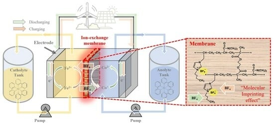
:
1. Introduction
2. Materials and Methods
2.1. Materials
2.2. Membrane Fabrication
2.3. Membrane Chacterizations
2.4. NARFB Performance Tests
3. Results and Discussion
4. Conclusions
Author Contributions
Funding
Data Availability Statement
Conflicts of Interest
References
- Mitali, J.; Dhinakaran, S.; Mohamad, A.A. Energy storage systems: A review. Energy Storage Sav. 2022, 1, 166–216. [Google Scholar] [CrossRef]
- Gür, T.M. Review of electrical energy storage technologies, materials and systems: Challenges and prospects for large-scale grid storage. Energy Environ. Sci. 2018, 11, 2696–2767. [Google Scholar] [CrossRef]
- Sun, C.-N.; Mench, M.M.; Zawodzinski, T.A. High performance redox flow batteries: An analysis of the upper performance limits of flow batteries using non-aqueous solvents. Electrochim. Acta 2017, 237, 199–206. [Google Scholar] [CrossRef]
- Hollas, A.; Wei, X.; Murugesan, V.; Nie, Z.; Li, B.; Reed, D.; Liu, J.; Sprenkle, V.; Wang, W. A biomimetic high-capacity phenazine-based anolyte for aqueous organic redox flow batteries. Nat. Energy 2018, 3, 508–514. [Google Scholar] [CrossRef]
- Runa, M.; Alghamdi, N.; Peng, X.; Huang, Y.; Wang, B.; Wang, L.; Gentle, I.R.; Hickey, S.; Luo, B. Scientific issues of zinc-bromine flow batteries and mitigation strategies. Exploration 2023, 3, 20220073. [Google Scholar] [CrossRef]
- Cabrera, P.J.; Yang, X.; Suttil, J.A.; Hawthorne, K.L.; Brooner, R.E.; Sanford, M.S.; Thompson, L.T. Complexes containing redox noninnocent ligands for symmetric, multielectron transfer nonaqueous redox flow batteries. J. Phys. Chem. C 2015, 119, 15882–15889. [Google Scholar] [CrossRef]
- Sharma, S.; Andrade, G.A.; Maurya, S.; Popov, I.A.; Batista, E.R.; Davis, B.L.; Mukundan, R.; Smythe, N.C.; Tondreau, A.M.; Yang, P. Iron-iminopyridine complexes as charge carriers for non-aqueous redox flow battery applications. Energy Storage Mater. 2021, 37, 576–586. [Google Scholar] [CrossRef]
- Yan, Y.; Vaid, T.P.; Sanford, M.S. Bis(diisopropylamino) cyclopropenium-arene cations as high oxidation potential and high stability catholytes for non-aqueous redox flow batteries. J. Am. Chem. Soc. 2020, 142, 17564–17571. [Google Scholar] [CrossRef]
- Chai, J.; Lashgari, A.; Cao, Z.; Williams, C.K.; Wang, X.; Dong, J.; Jiang, J. PEGylation-enabled extended cyclability of a non-aqueous redox flow battery. ACS Appl. Mater. Interfaces 2020, 12, 15262–15270. [Google Scholar] [CrossRef]
- Tung, S.; Fisher, S.L.; Kotov, N.A.; Thompson, L.T. Nanoporous aramid nanofibre separators for nonaqueous redox flow batteries. Nat. Commun. 2018, 9, 4193–4201. [Google Scholar] [CrossRef]
- Li, Y.; Sniekers, J.; Malaquias, J.C.; Van Goethem, C.; Binnemans, K.; Fransaer, J.; Vankelecom, I.F. Crosslinked anion exchange membranes prepared from poly (phenylene oxide)(PPO) for non-aqueous redox flow batteries. J. Power Sources 2018, 378, 338–344. [Google Scholar] [CrossRef]
- Huang, Y.; Gu, S.; Yan, Y.; Li, S.F.Y. Nonaqueous redox-flow batteries: Features, challenges, and prospects. Curr. Opin. Chem. Eng. 2015, 8, 105–113. [Google Scholar] [CrossRef]
- Cammack, C.X.; Pratt, H.D.; Small, L.J.; Anderson, T.M. A higher voltage Fe (II) bipyridine complex for non-aqueous redox flow batteries. Dalton Trans. 2021, 50, 858–868. [Google Scholar] [CrossRef] [PubMed]
- Davis, C.M.; Boronski, C.E.; Yang, T.; Liu, T.; Liang, Z. Molecular Engineering of Redox Couples for Non-Aqueous Redox Flow Batteries. Batteries 2023, 9, 504. [Google Scholar] [CrossRef]
- Gong, K.; Fang, Q.; Gu, S.; Li, S.F.Y.; Yan, Y. Nonaqueous redox-flow batteries: Organic solvents, supporting electrolytes, and redox pairs. Energy Environ. Sci. 2015, 8, 3515–3530. [Google Scholar] [CrossRef]
- Xu, T. Ion exchange membranes: State of their development and perspective. J. Membr. Sci. 2005, 263, 1–29. [Google Scholar] [CrossRef]
- Kosswattaarachchi, A.M.; Cook, T.R. Concentration-dependent charge-discharge characteristics of non-aqueous redox flow battery electrolyte combinations. Electrochim. Acta 2018, 261, 296–306. [Google Scholar] [CrossRef]
- Chai, J.; Lashgari, A.; Wang, X.; Williams, C.K.; Jiang, J. All-PEGylated redox-active metal-free organic molecules in non-aqueous redox flow battery. J. Mater. Chem. A 2020, 8, 15715–15724. [Google Scholar] [CrossRef]
- Hendriks, K.H.; Sevov, C.S.; Cook, M.E.; Sanford, M.S. Multielectron Cycling of a low-potential anolyte in alkali metal electrolytes for nonaqueous redox flow batteries. ACS Energy Lett. 2017, 2, 2430–2435. [Google Scholar] [CrossRef]
- Kwon, H.-G.; Bae, I.; Choi, S.-H. Crosslinked poly (arylene ether ketone) membrane with high anion conductivity and selectivity for non-aqueous redox flow batteries. J. Membr. Sci. 2021, 620, 118928. [Google Scholar] [CrossRef]
- Mazumder, M.M.R.; Jadhav, R.G.; Minteer, S.D. Phenyl Acrylate-Based Cross-Linked Anion Exchange Membranes for Non-aqueous Redox Flow Batteries. ACS Mater. Au 2023, 3, 557–568. [Google Scholar] [CrossRef] [PubMed]
- Mun, J.; Lee, M.-J.; Park, J.-W.; Oh, D.-J.; Lee, D.-Y.; Doo, S.-G. Non-aqueous redox flow batteries with nickel and iron tris (2,2′-bipyridine) complex electrolyte. Electrochem. Solid-State Lett. 2012, 15, A80. [Google Scholar] [CrossRef]
- Park, M.-S.; Lee, N.-J.; Lee, S.-W.; Kim, K.J.; Oh, D.-J.; Kim, Y.-J. High-energy redox-flow batteries with hybrid metal foam electrodes. ACS Appl. Mater. Interfaces 2014, 6, 10729–10735. [Google Scholar] [CrossRef] [PubMed]
- Kim, D.-H.; Seo, S.-J.; Lee, M.-J.; Park, J.-S.; Moon, S.-H.; Kang, Y.S.; Choi, Y.-W.; Kang, M.-S. Pore-filled anion-exchange membranes for non-aqueous redox flow batteries with dual-metal-complex redox shuttles. J. Membr. Sci. 2014, 454, 44–50. [Google Scholar] [CrossRef]
- Veerman, J.; Gómez-Coma, L.; Ortiz, A.; Ortiz, I. Resistance of ion exchange membranes in aqueous mixtures of monovalent and divalent ions and the effect on reverse electrodialysis. Membranes 2023, 13, 322. [Google Scholar] [CrossRef]
- Hagesteijn, K.F.L.; Jiang, S.; Ladewig, B.P. A review of the synthesis and characterization of anion exchange membranes. J. Mater. Sci. 2018, 53, 11131–11150. [Google Scholar] [CrossRef]
- Klaysom, C.; Moon, S.-H.; Ladewig, B.P.; Lu, G.M.; Wang, L. Preparation of porous ion-exchange membranes (IEMs) and their characterizations. J. Membr. Sci. 2011, 371, 37–44. [Google Scholar] [CrossRef]
- Jeevananda, T.; Yeon, K.-H.; Moon, S.-H. Synthesis and characterization of bipolar membrane using pyridine functionalized anion exchange layer. J. Membr. Sci. 2006, 283, 201–208. [Google Scholar] [CrossRef]
- Jia, C.; Liu, J.; Yan, C. A significantly improved membrane for vanadium redox flow battery. J. Power Sources 2010, 195, 4380–4383. [Google Scholar] [CrossRef]
- Bang, H.S.; Kim, D.; Hwang, S.S.; Won, J. Surface-modified porous membranes with electrospun Nafion/PVA fibres for non-aqueous redox flow battery. J. Membr. Sci. 2016, 514, 186–194. [Google Scholar] [CrossRef]
- Lu, W.; Shao, Z.-G.; Zhang, G.; Li, J.; Zhao, Y.; Yi, B. Preparation of anion exchange membranes by an efficient chloromethylation method and homogeneous quaternization/crosslinking strategy. Solid State Ion. 2013, 245, 8–18. [Google Scholar] [CrossRef]
- Jheng, L.-C.; Hsu, C.-Y.; Yeh, H.-Y. Anion exchange membranes based on imidazoline quaternized polystyrene copolymers for fuel cell applications. Membranes 2021, 11, 901. [Google Scholar] [CrossRef]
- Balan, V.; Mihai, C.; Cojocaru, F.; Uritu, C.; Dodi, G.; Botezat, D.; Gardikiotis, I. Vibrational spectroscopy fingerprinting in medicine: From molecular to clinical practice. Materials 2019, 12, 2884. [Google Scholar] [CrossRef]
- Wang, W.; Li, S. Improvement of dielectric breakdown performance by surface modification in polyethylene/TiO2 nanocomposites. Materials 2019, 12, 3346. [Google Scholar] [CrossRef]
- Łyszczek, R.; Podkościelna, B.; Lipke, A.; Ostasz, A.; Puszka, A. Synthesis and thermal characterization of luminescent hybrid composites based on bisphenol A diacrylate and NVP. J. Therm. Anal. Calorim. 2019, 138, 4463–4473. [Google Scholar] [CrossRef]
- Shin, W.S.; Li, X.F.; Scgwartz, B.; Wunder, S.L.; Baran, G.R. Determination of the degree of cure of dental resins using Raman and FT-Raman spectroscopy. Dent. Mater. 1993, 9, 317–324. [Google Scholar] [CrossRef]
- Lei, M.; Zhang, Q.; Chi, M.; Yu, Y.; Jiang, H.; Wang, S.; Min, D. Anion Exchange membrane with High hydroxide ion conductivity and robust tensile strength fabricated from quaternary ammonia functionalized Pinus contorta, Dougl. Chip. Ind. Crops Prod. 2021, 166, 113458. [Google Scholar] [CrossRef]
- Khan, M.I.; Mondal, A.N.; Tong, B.; Jiang, C.; Emmanuel, K.; Yang, Z.; Wu, L.; Xu, T. Development of BPPO-based anion exchange membranes for electrodialysis desalination applications. Desalination 2016, 391, 61–68. [Google Scholar] [CrossRef]
- Kaneto, K.; Hata, F.; Uto, S. Structure and size of ions electrochemically doped in conducting polymer. J. Micromech. Microeng. 2018, 28, 054003. [Google Scholar] [CrossRef]
- Kubota, S.; Ozaki, S.; Onishi, J.; Kano, K.; Shirai, O. Selectivity on ion transport across bilayer lipid membranes in the presence of gramicidin A. Anal. Sci. 2009, 25, 189–193. [Google Scholar] [CrossRef]
- Sillars, F.B.; Fletcher, S.I.; Mirzaeian, M.; Hall, P.J. Variation of electrochemical capacitor performance with room temperature ionic liquid electrolyte viscosity and ion size. Phys. Chem. Chem. Phys. 2012, 14, 6094–6100. [Google Scholar] [CrossRef]
- Yoshikawa, M.; Tharpa, K.; Dima, S. Molecularly imprinted membranes: Past, present, and future. Chem. Rev. 2016, 116, 11500–11528. [Google Scholar] [CrossRef]
- ul Haq, O.; Choi, J.; Lee, Y. Anion-exchange membrane for membrane capacitive deionization prepared via pore-filling polymerization in a porous polyethylene supporting membrane. React. Funct. Polym. 2018, 132, 36–42. [Google Scholar] [CrossRef]
- Lehmann, M.L.; Tyler, L.; Self, E.C.; Yang, G.; Nanda, J.; Saito, T. Membrane design for non-aqueous redox flow batteries: Current status and path forward. Chem 2022, 8, 1611–1616. [Google Scholar] [CrossRef]


| Name | Chemical Structure | Mw (g/mol) |
|---|---|---|
| Ethylene glycol dimethacrylate (EGDMA) |  | 198.22 |
| 1,3-Butanediol dimethacrylate (BDDMA) |  | 226.27 |
| 1,6-Hexanediol dimethacrylate (HDDMA) |  | 254.32 |
| Bisphenol A dimethacrylate (BPADMA) |  | 364.43 |
| Membranes | Thickness (μm) | IEC (meq./g) | WU (%) | MER (1) (Ω cm2) | MER (2) (Ω cm2) | TN (-) |
|---|---|---|---|---|---|---|
| FAP4 (Fumatech) | 50 | 0.71 | 16.0 | 2.86 | 28.6 | 0.946 |
| PFAEM–EGDMA | 25 | 1.92 | 61.1 | 1.44 | 1.87 | 0.956 |
| PFAEM–BDDMA | 25 | 1.95 | 59.3 | 1.60 | 3.02 | 0.944 |
| PFAEM–HDDMA | 25 | 1.78 | 64.6 | 1.50 | 2.84 | 0.946 |
| PFAEM–BPADMA | 25 | 1.59 | 56.9 | 1.45 | 2.76 | 0.928 |
| Membranes | Tensile Strength (MPa) | Elongation at Break (%) |
|---|---|---|
| FAP4 (Fumatech) | 46.2 | 14.5 |
| Porous support | 154.0 | 88.3 |
| PFAEM | 166.1 | 76.2 |
| ABIMBF4:DMAA (Mole Ratio) | IEC (meq./g) | WU (%) | SU (%) | MER (1) (Ω cm2) | σ (2) (mS/cm) |
|---|---|---|---|---|---|
| 0.1:1 | 1.25 | 29.6 | 25.0 | 76.7 | 0.033 |
| 0.2:1 | 1.38 | 27.8 | 24.7 | 43.5 | 0.057 |
| 0.4:1 | 1.55 | 29.7 | 35.6 | 9.41 | 0.276 |
| 0.6:1 | 1.78 | 50.2 | 44.1 | 3.31 | 0.756 |
| 0.8:1 | 1.79 | 55.7 | 48.4 | 2.99 | 0.870 |
| 1.0:1 | 1.90 | 56.2 | 53.9 | 2.15 | 1.011 |
| Membranes | P_Fe(bpy)32+ (cm2/s) |
|---|---|
| FAP4 (Fumatech) | 9.72 × 10⁻⁹ |
| PFAEM (ABIMBF4:DMAA = 0.6:1) | 1.56 × 10⁻¹² |
| Membranes | WU (%) | IEC (meq./g) | MER (1) (Ω cm2) | σ (2) (mS/cm) | TN (-) | LCD (mA/cm2) | ε (-) |
|---|---|---|---|---|---|---|---|
| PFAEM (fresh) | 32.35 | 2.01 | 2.18 | 1.15 | 0.972 | 2.80 | 0.904 |
| PFAEM (aged) | 40.48 | 1.89 | 2.68 | 0.93 | 0.938 | 2.93 | 0.895 |
Disclaimer/Publisher’s Note: The statements, opinions and data contained in all publications are solely those of the individual author(s) and contributor(s) and not of MDPI and/or the editor(s). MDPI and/or the editor(s) disclaim responsibility for any injury to people or property resulting from any ideas, methods, instructions or products referred to in the content. |
© 2023 by the authors. Licensee MDPI, Basel, Switzerland. This article is an open access article distributed under the terms and conditions of the Creative Commons Attribution (CC BY) license (https://creativecommons.org/licenses/by/4.0/).
Share and Cite
Song, H.-B.; Kim, D.-H.; Lee, M.-J.; Kang, M.-S. Thin Reinforced Anion-Exchange Membranes for Non-Aqueous Redox Flow Battery Employing Fe/Co-Metal Complex Redox Species. Batteries 2024, 10, 9. https://doi.org/10.3390/batteries10010009
Song H-B, Kim D-H, Lee M-J, Kang M-S. Thin Reinforced Anion-Exchange Membranes for Non-Aqueous Redox Flow Battery Employing Fe/Co-Metal Complex Redox Species. Batteries. 2024; 10(1):9. https://doi.org/10.3390/batteries10010009
Chicago/Turabian StyleSong, Hyeon-Bee, Do-Hyeong Kim, Myung-Jin Lee, and Moon-Sung Kang. 2024. "Thin Reinforced Anion-Exchange Membranes for Non-Aqueous Redox Flow Battery Employing Fe/Co-Metal Complex Redox Species" Batteries 10, no. 1: 9. https://doi.org/10.3390/batteries10010009