Article

Effect of Electrode–Normal Magnetic Field on the Motion of Hydrogen Bubbles

1
Department of Mechanical Engineering, National Yang Ming Chiao Tung University, Hsinchu 300, Taiwan
2
Department of Mechanical and Aerospace Engineering, Chung-Cheng Institute of Technology, National Defense University, Taoyuan 335, Taiwan
*
Authors to whom correspondence should be addressed.
Magnetochemistry 2023, 9(12), 233; https://doi.org/10.3390/magnetochemistry9120233
Submission received: 26 October 2023 / Revised: 12 December 2023 / Accepted: 14 December 2023 / Published: 18 December 2023
(This article belongs to the Special Issue Advances in Electrochemical Properties of Magnetic Materials)

Abstract

:
In comparison to alternative methods for hydrogen production, water electrolysis stands out as the optimal means for obtaining ultra-pure hydrogen. However, its widespread adoption is significantly hampered by its low energy efficiency. It has been established that the introduction of an external magnetic field can mitigate energy consumption, consequently enhancing electrolysis efficiency. While much of the research has revealed that an electrode–parallel magnetic field plays a crucial role in enhancing the bubble detachment process, there has been limited exploration of the effect of electrode–normal magnetic fields. In this work, we compare the water electrolysis efficiency of a circular electrode subjected to electrode–normal magnetic field resulting in a magnet edge effect and electrode edge effect by varying the sizes of the magnet and electrode. The findings indicate that a rotational flow caused by the Lorentz force facilitates the detachment of the hydrogen from the electrode surface. However, the rotation direction of hydrogen gas bubbles generated by the magnet edge effect is opposite to that of electrode edge effect. Furthermore, the magnet edge effect has more significant influence on the hydrogen bubbles’ locomotion than the electrode edge effect. With an electrode gap of 30 mm, employing the magnet edge effect generated by a single magnet leads to an average of 4.9% increase in current density. On the other hand, the multiple magnet effects created by multiple small magnets under the electrode can further result in an average 6.6% increase in current density. Nevertheless, at an electrode spacing of 50 mm, neither the magnet edge effect nor the electrode edge effect demonstrates a notable enhancement in conductivity. In reality, the electrode edge effect even leads to a reduction in conductivity.

1. Introduction

Water electrolysis (WE) is widely acknowledged as the best hydrogen production technique that is able to produce hydrogen in high volume with high purity. Numerous investigations into hydrogen production through WE have been carried out, incorporating various process enhancements, including alkaline water electrolysis (AWE) [1], proton exchange membrane (PEM) electrolysis [2], and solid oxide electrolysis cells (SOEC) [3]. Despite being the most straightforward method for obtaining pure hydrogen, the efficiency of WE remains relatively low [4]. The typical efficiency of alkaline WE stands at 70%, while PEM electrolysis achieves 80% [5]. Consequently, there is no WE method with an efficiency exceeding 90%.
Numerous endeavors have been undertaken to enhance WE efficiency, particularly in the field of catalyst design [6]. Considering the challenges associated with electrocatalyst preparation and aging, several alternative efficiency-enhancing approaches that are easy to implement have been developed. These include the use of porous electrodes [7,8,9], the application of external fields [10,11,12,13], an intensified electrode arrangement [14], and ultrasonic vibration [15]. The utilization of an external magnetic field has garnered significant attention from researchers due to its cost-effectiveness, as it can be achieved using readily available permanent magnets without the need for additional energy input.
Magnetic fields have the ability to create a Lorentz force within the electrolyte [16,17]. Lorentz force, also described as a magnetohydrodynamic (MHD) force, augments the possibility of mechanically controlling the electrolysis process through magnetic field exposure [18,19,20]. Additionally, the convective flow assists in the efficient removal of gas bubbles from the electrode surfaces. Notably, the application of magnetic fields oriented perpendicularly to the hydrogen evolution reaction (HER) electrodes has been shown to result in reduced overpotentials [21]. It has been demonstrated that a paramagnetic electrode has a more significant effect on bubble locomotion than a diamagnetic electrode, which results in larger efficiency improvements on water electrolysis [17,22].
These MHD convections are commonly instigated by a magnetic field either parallel or normal to the electrodes. Numerous studies have revealed that magnetic fields parallel to the electrodes play a crucial role in enhancing the bubble detachment process, diminishing the ohmic voltage drop and elevating the overall efficiency of water electrolysis [9,19,20,23,24,25]. Given the prevalence of disk-shaped units in commercial electrolytic cell stacks, it is impractical to position the external magnetic field perpendicular to the electric field; that is, the magnetic field is parallel to the electrode surface. Some studies have demonstrated that even with this electrode–normal magnetic field arrangement, there is a significant disturbance that enhances water electrolysis efficiency [13,26]. This enhancement is attributed to the twisting of the electric field by bubbles and electrode edges, giving rise to the Lorentz force [27,28,29]. On the other hand, the other reports showed that magnetic fields normal to the electrodes in a square electrolyzer can increase liquid hydrodynamics, thus addressing challenges such as the coalescence of bubbles and the uneven distribution of electrolyte composition and temperature in a limited space [22,30]. The azimuthal Lorentz force may be caused by the magnet edge effect, whose mechanism has not been explained well.
Our ongoing research reveals that, in comparison to prior studies, the locomotion of hydrogen bubbles under an electrode–normal magnetic field exhibits notable differences and proves to be intriguing. The primary objective of this work is to investigate the distinctive hydrogen bubble behaviors within an electrolytic cell under the influence of the magnet edge effect and electrode edge effect. The underlying mechanisms are analyzed and the comparison of the electrolysis efficiency under the edge effect is discussed as well.

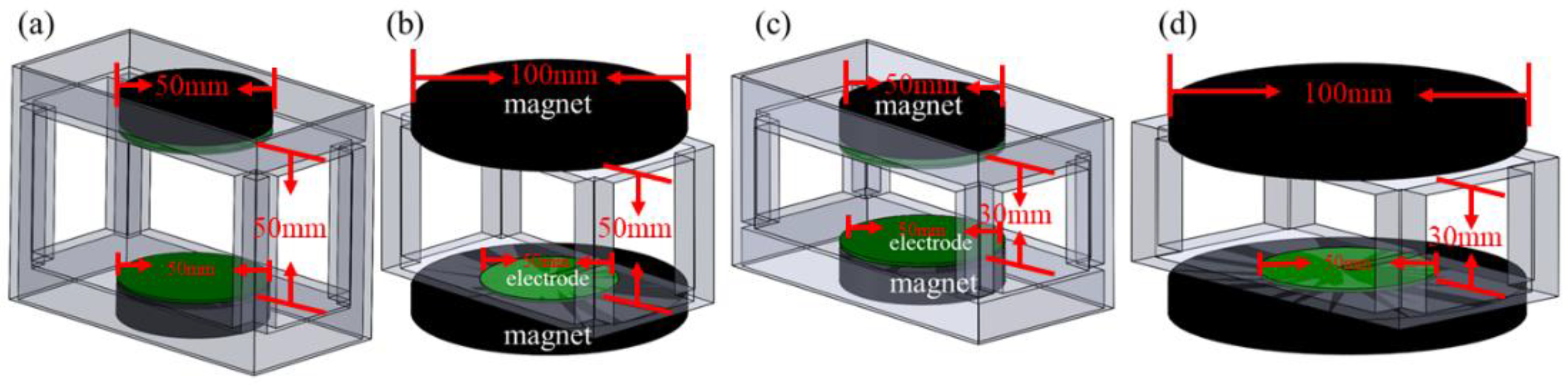
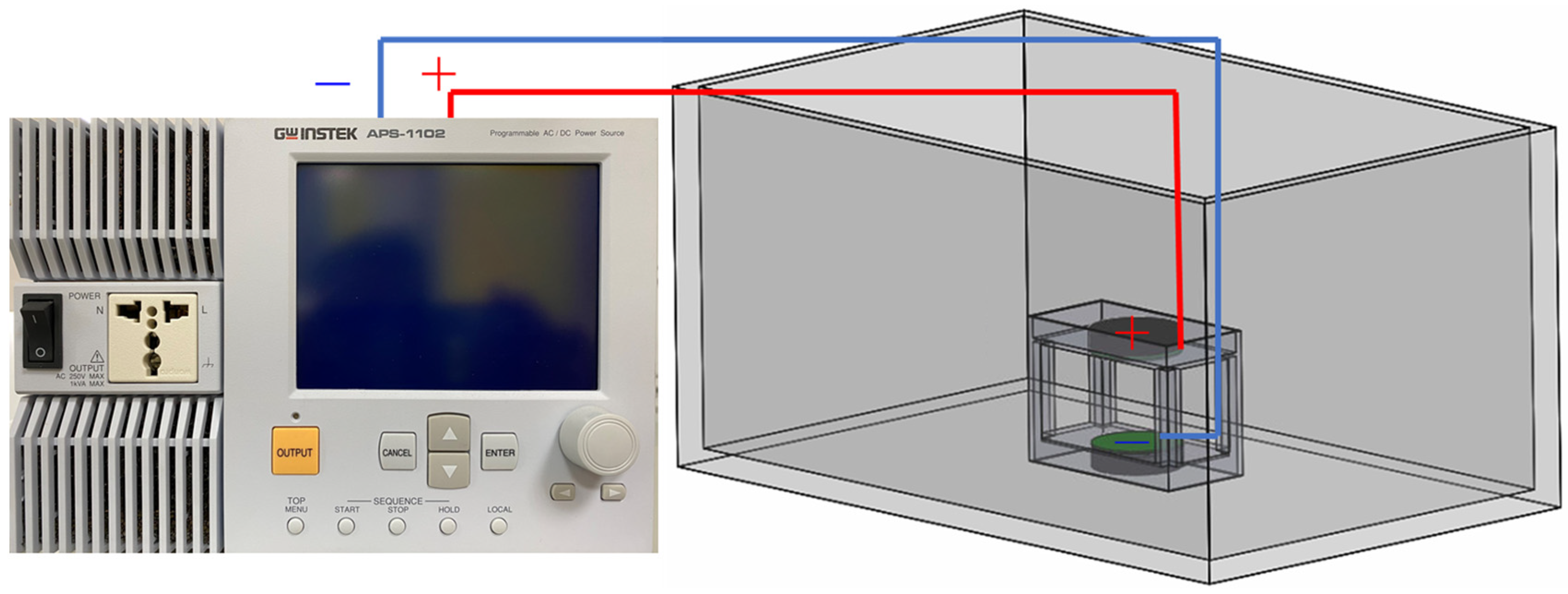
2. Material and Methods

Figure 1 shows the four electrode–normal magnetic field configurations designed to create the magnet edge effect and electrode edge effect near the surface of the electrode and to allow the observation of the movement of hydrogen bubbles. Two circular platinum titanium electrode plates with a diameter of 50 mm faced two parallel N35 magnets whose maximum field strength near the surface was about 0.3 T. The two diameters of the N35 magnet were 50 mm and 100 mm, and were designed for the generation of the magnet edge effect and electrode edge effect, respectively. The two distances between the electrodes, of 50 mm and 30 mm, generated a weaker and stronger field strength, respectively. The adjustable electrical field was generated by a power supply (GWInstek APS-1102) connected to the two circular electrodes, as shown in Figure 2. The initial experiment was conducted by applying voltages of 100 V, 120 V, 150 V, 180 V, and 200 V to the 50 mm spaced electrodes without magnets. The measurements of the current were 0.335 A, 0.4 A, 0.49 A, 0.57 A, and 0.63 A.
The major factor acting on the locomotion behavior of the hydrogen bubble on the electrode surface is mainly the net Lorentz force acting on the bubbles, which involves the MHD force and hydrodynamic drag, so understanding the magnetic, electric, and flow fields is crucial. The governing equations of hydrodynamics with the incorporated Lorentz force in an incompressible Newtonian fluid are expressed as augmented Navier–Stokes equations [18]:
ρ u = 0
ρ u τ + ( u ) u = pI + μ ( u + ( u ) T ) + F L
F L = J × B
where I, ρ, u, and μ are the unit tensor, fluid density, velocity, and the viscosity coefficient, respectively. FL is the body force density, which represents the density of the Lorentz force, J is the current density, and B is the magnetic flux density. The current density of electrochemical process is [18] as follows:
J = σ E + j e
E = φ
Here, E is the electric field density, σ is the electrical conductivity, φ is the electric potential, and je is the current density caused by ion migration, which can be neglected here. Assuming that the electrolyte conductivity distribution is uniform, the effect of the non-uniform electrical field can be ignored. The set of equations is numerically solved by COMSOL multiphysics.
Water electrolysis involves the separation of water into its constituent elements, hydrogen and oxygen, through the utilization of electrical energy. In the case of electrolyzing distilled water, the balanced acid-driven half-reactions for the hydrogen evolution reaction (HER) occurring at the cathode and the oxygen evolution reaction (OER) taking place at the anode can be expressed as follows:
2 H+ + 2 e → H2
2 H2O → O2 + 4 H+ + 4e
The upper electrode and lower electrode plate are set as the anode and cathode, respectively. In this study, the behavior of the bubbles derived from the bottom electrode plate will be discussed.
During water electrolysis, the gas production is proportional to the electric current. This study plots the I–V curves and compares the conductivity of the electrolyte for the magnet edge effect, electrode edge effect, inter-electrode distances, and varying electric voltage.

3. Results and Discussion

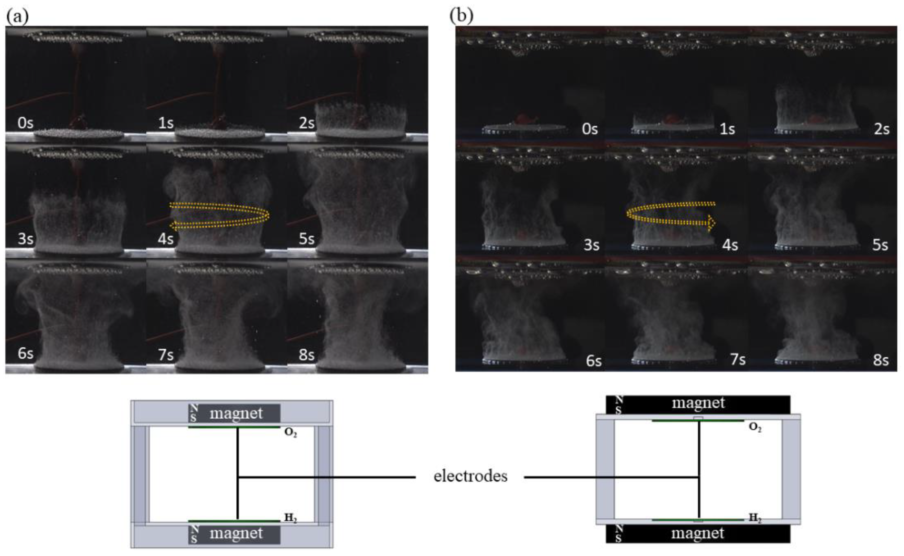
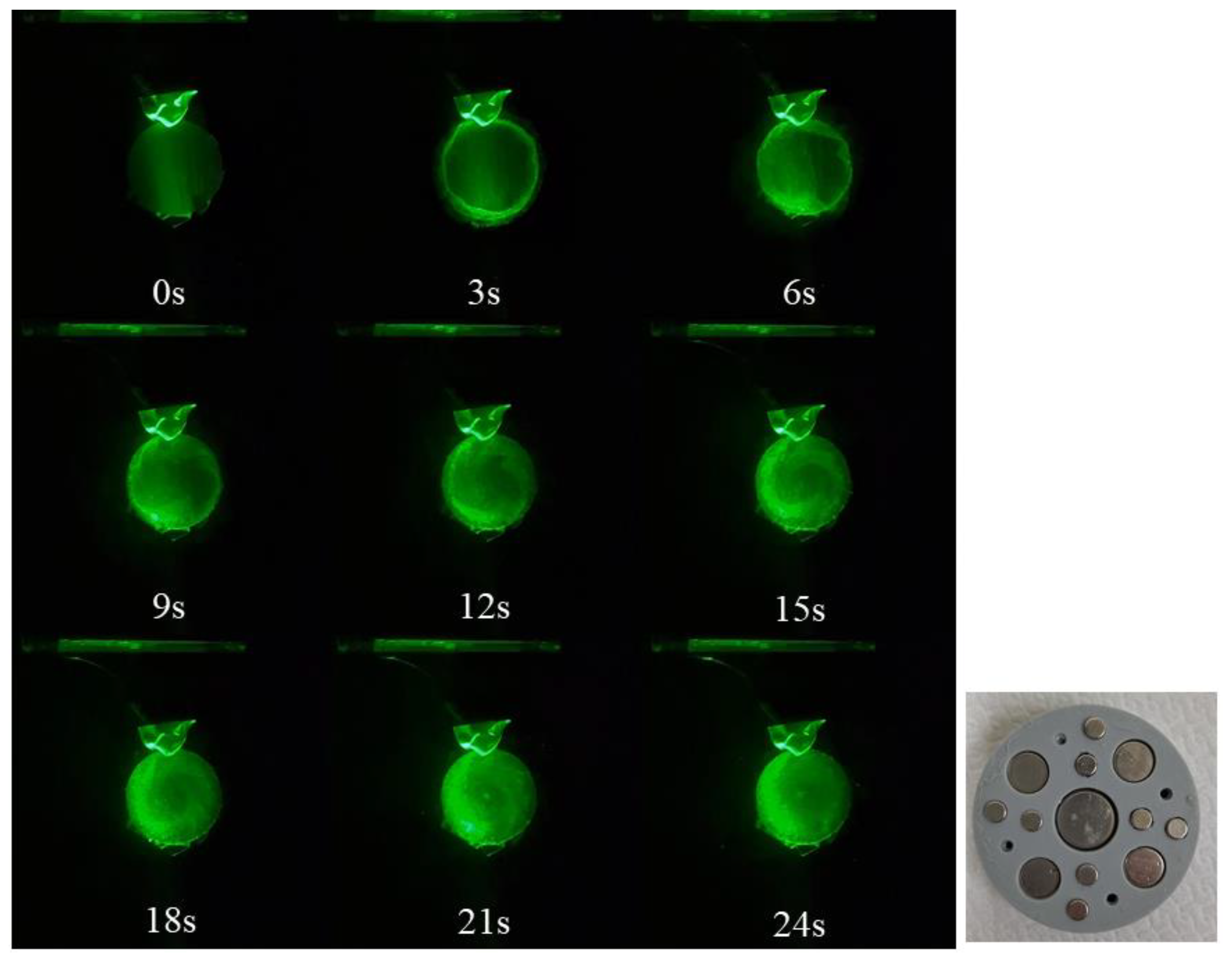
3.1. Influence of Magnet Edge and Electrode Edge on the Movement of the Gas Bubbles

From Equation (3), it is evident that to generate the Lorentz force, the electric field and magnetic field must be perpendicular to each other. As observed in the experimental results in Figure 3, even though the permanent magnets and electrode plates are arranged in parallel, a horizontal Lorentz force is generated at the edges of the electrode plates. This results in the phenomenon of bubbles at the edge of the electrode plate rotating either clockwise or counterclockwise. Simultaneously, under the influence of buoyancy, these bubbles induce the formation of a rotational vortex on the electrode plate’s surface, expediting the detachment of the overall bubbles. Figure 3a,b show that the bubbles experience Lorentz forces in opposite directions under the influence of the magnet edge and electrode edge, resulting in reverse vortex rotation. The direction of the Lorentz force caused by the magnet and electrode edge effect can be explained through the magnetic flux density simulation in Figure 4.
Figure 4 illustrates the distribution of magnetic field lines simulated using the COMSOL Multiphysics® 6.1 software for the same electrode plate under the influence of different magnetic field configurations. The inner orange box represents the position of the electrode plate, with the upper and lower being the anode and cathode, respectively. The outer upper and lower black boxes represent the N35 permanent magnets, with a field strength of 0.3 T on the edge surface. The upper and lower sides of the magnet are set as the N-pole and S-pole, respectively. As observed from the simulation results in Figure 4a, in the region near the center of the magnet, magnetic field lines flow from the N-pole to the S-pole, forming a vertically uniform magnetic field. However, in the vicinity of the magnet’s edge, there is a curved distribution of magnetic field lines, resulting in a distortion of the magnetic field. The magnetic field lines at the edge of the magnet are nearly horizontal, intersecting with the vertically oriented electric field and creating a Lorentz force. Under this configuration, the Lorentz force at the edge of the lower electrode plate will be clockwise, as shown in Figure 5a. As the size of the magnet matches that of the electrode plate, this Lorentz force will drive the bubbles at the edge of the lower electrode plate to rotate clockwise, creating a bubble swirl, as shown in Figure 3a.
When the magnet is larger than the electrode plate, the distribution of magnetic field lines, as shown in Figure 4b, indicates that the electrode plate is subjected to a magnet edge effect. The magnetic field direction is from bottom to top, while the current direction is from top to bottom. Since the side of the electrode plate still has conductivity, an inward and horizontal current that intersects with the upward magnetic field would result in a counterclockwise Lorentz force, as illustrated in Figure 5b. This makes the bubbles at the edge of the lower electrode plate rotate counterclockwise, forming a bubble swirl, as shown in Figure 3b. Figure 5c and Figure 5d, respectively, show the simulation results of the electric field distribution for the magnet and electrode edge effect arrangement. It can be seen that the horizontal electric field occurs near the edge of the electrode because of the conductive side edge.

3.2. Effect of Electrode Spacing on the Movement of Gas Bubbles

Based on a previous report, it is known that in the electrolysis process, a shorter electrode plate distance results in higher electrolysis efficiency [22]. In order to understand the influence of different electrode spacing and edge effects on bubble movement, this study investigates the effects of the magnet edge and electrode edge under conditions of electrode plate spacing at 30 mm and 50 mm, respectively.
Figure 3a,b demonstrate the movement of bubbles on the electrode plate surface under the influence of the magnet edge and electrode edge with an electrode plate spacing of 50 mm and a fixed voltage of 100 V. Figure 6 shows the bubble movement when the electrode plate spacing is reduced to 30 mm under the same configurations for magnets and electrode plates. In comparison with Figure 3, it is evident that with a shorter electrode plate spacing, a greater number of bubbles are generated simultaneously, indicating that a shorter electrode plate spacing leads to higher electrolysis efficiency, consistent with the findings in the literature [22].

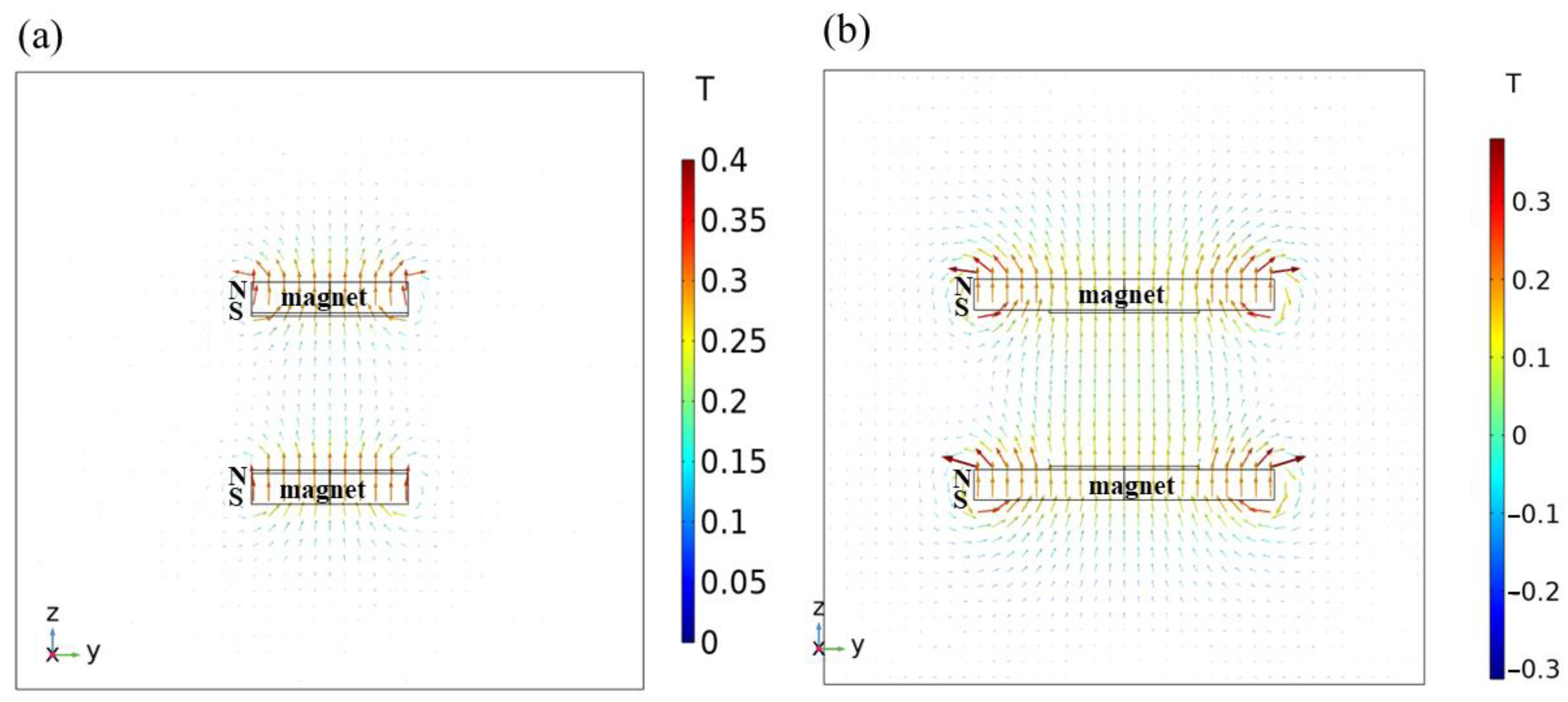
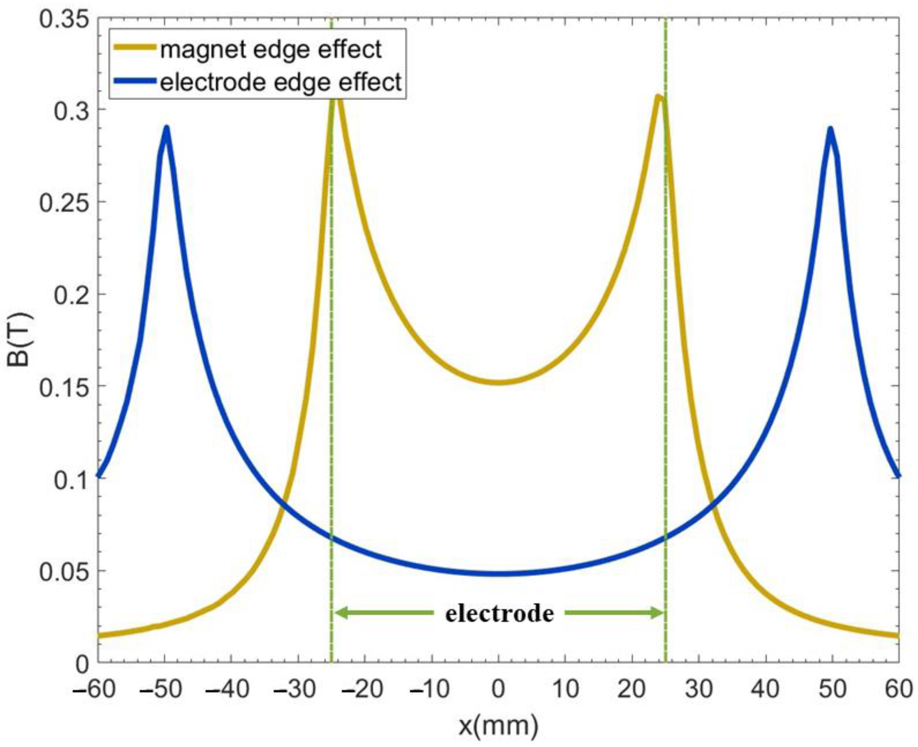
3.3. Impact of the Magnet and Electrode Edge Effect on the Lorentz Force on the Electrode Surface

To obtain a deeper understanding of the efficiency of the magnet and electrode edge effect in promoting bubble detachment, this study calculates the magnitude and direction of the Lorentz force under the experimental setup depicted in Figure 3. This was carried out to comprehend the benefits of the magnet and electrode edge effect in facilitating bubble detachment from the electrode plate. As shown in the simulation results in Figure 7a, a magnet edge effect generates a clockwise Lorentz force on the lower electrode plate, while Figure 7b illustrates that an electrode edge effect forms a counterclockwise Lorentz force on the lower electrode plate. These results align with the experimental findings shown in Figure 3.
The distribution of the Lorentz force along the central axis of the electrode plate surface is depicted in Figure 8. From Figure 8a,b, it is evident that, whether in with magnet or electrode edge effect, the maximum Lorentz force occurs at the two ends of the electrode, with equal magnitudes and opposite directions. As one moves towards the center of the electrode plate, the Lorentz force rapidly decreases towards zero. Furthermore, with a magnet edge effect (Figure 8a), the maximum Lorentz force density is approximately 0.056 N/m3, significantly greater than the maximum Lorentz force produced with an electrode edge effect (Figure 8b), which is about 0.045 N/m3, representing a difference of 1.2 times.
Figure 9 illustrates the calculation of the Lorentz force when the electrode plate spacing is reduced to 30 mm. The trend is similar to the 50 mm configuration, with the maximum Lorentz force density with the magnet and electrode edge effect being approximately 0.065 N/m3 (Figure 9a) and 0.058 N/m3, respectively, representing a difference of about 1.1 times. These results indicate that reducing the electrode plate spacing enhances the Lorentz force, further promoting bubble detachment. Additionally, the difference in the impact of the magnet and electrode edge effect on the magnitude of the Lorentz force density slightly decreases when the electrode spacing is reduced.

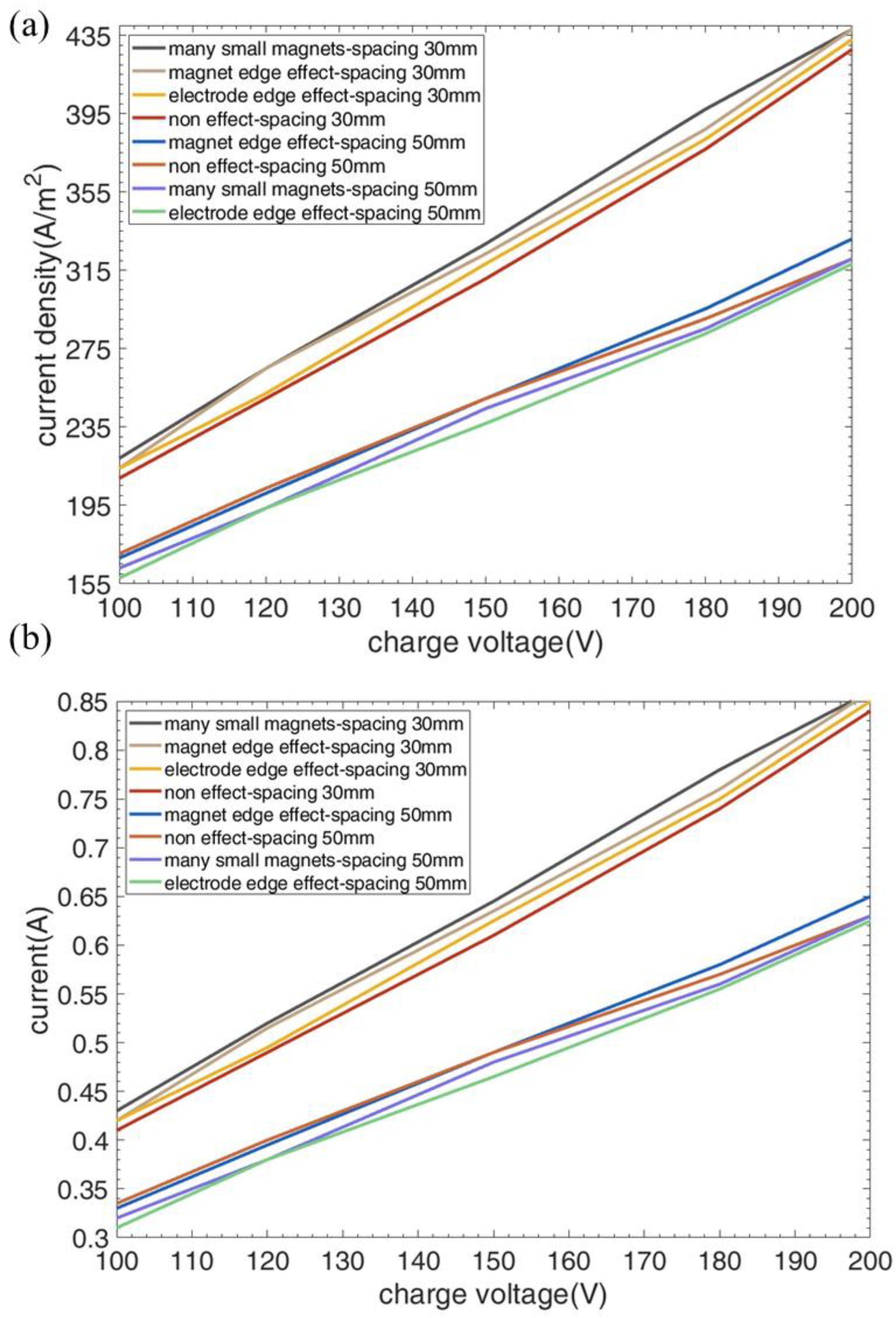
3.4. Comparison of Various Experimental Configurations for Improving Current Density Efficiency

To obtain a practical understanding of the Lorentz forces resulting from edge effects, electrode spacing, and voltage intensity, and their impact on promoting the detachment of bubbles from the electrode surface and enhancing conductivity, this study concludes by comparing the current density measurements across various experimental configurations. This comparison serves to identify the optimal configuration for improving the efficiency of hydrogen production via water electrolysis. Figure 10 shows that the current density and the current exhibited a linear increase with a higher applied voltage for all cases. Notably, when the electrode spacing is reduced to 30 mm, the slope is steeper, indicating higher efficiency at smaller electrode spacings during high-voltage electrolysis. However, for an electrode spacing of 50 mm, both the magnet edge effect and the electrode edge effect show no significant improvement in conductivity. In fact, the electrode edge effect even results in a decrease in conductivity.
Furthermore, regardless of whether a magnet and electrode edge effect is applied, the current density at an electrode spacing of 30 mm is approximately 23% higher than at 50 mm. This observation suggests that reducing the electrode spacing generates greater Lorentz forces, which promote bubble detachment from the electrode surface. At an electrode spacing of 30 mm, the use of a magnet edge effect results in an average of a 4.9% increase in current density compared to the electrode without any effect, i.e., where no electro-parallel magnet is employed. On the other hand, the multiple magnet effects created by multiple small magnets under the electrode can further result in an average of a 6.6% increase in current density. This phenomenon can be illustrated by Figure 11, which shows the top view of the sequential images of the bubbles’ detachment influenced by the multiple small magnets under the electrode. Figure 11 shows that bubbles nucleate more rapidly from the rim of the electrode due to the strongest current intensity at the edge of the electrode plate. Subsequently, influenced by the edge effect generated by numerous small magnets beneath the electrode plate, bubbles rotate in the counter-clockwise direction, forming multiple bubble swirls. Those multiple swirls can make the bubbles detach from the electrode surface more quickly and increase the conductivity. As a result, the edge effect caused by multiple small magnets has a more significant influence than the edge effect formed by a single magnet.
Based on the experimental findings, it is evident that a magnet edge effect generates a larger Lorentz force compared to an electrode edge effect on the edge of the electrode surface. This phenomenon aids in faster bubble detachment. To understand this mechanism further, the magnetic field distribution on the electrode plate surface is analyzed in Figure 12. The green dashed line represents the electrode plate position. It is apparent that under the configuration of a magnet edge effect, the magnetic field intensity is greatest at the edge of the electrode plate, resulting in the highest Lorentz force. In contrast, in the case of an electrode edge effect, the electrode plate is located centrally within the large magnet, and is exposed to a more uniform and lower magnetic field. This leads to a smaller Lorentz force and reduced bubble detachment and electrolysis efficiency compared to the magnet edge effect. According to the experimental results of this study, the addition of a parallel magnet of the same size as the electrode plate can generate a magnet edge effect to accelerate bubble detachment and improve electrolysis efficiency. Furthermore, magnet edge effects generated by multiple small magnets under electrodes can further enhance the current density by creating multiple bubble swirls.

4. Conclusions

This study determines the effects of magnet edge and electrode edge on the water electrolysis efficiency by using various electrode–normal magnetic field configurations. When the magnets and electrode plates are parallel, the electrode edges experience a horizontal Lorentz force, leading to the rotation of bubbles at the electrode plate’s edge, either clockwise or counterclockwise. These bubbles also induce the formation of a rotational vortex on the electrode plate’s surface, aiding bubble detachment. The experimental results indicate that employing a magnet edge effect results in a greater Lorentz force, which accelerates bubble detachment from the electrode surface more significantly. Furthermore, it is observed that reducing the electrode spacing leads to a faster bubble detachment. The study concludes with a comparison of various experimental configurations, demonstrating that reducing the electrode spacing and applying a magnet edge effect lead to increased current density and enhanced electrolysis efficiency. This work offers valuable insights into optimizing the efficiency of hydrogen production through water electrolysis by edge effect and controlling electrode spacing and voltage intensity, ultimately contributing to the development of sustainable and cost-effectiveness hydrogen production methods, as these can be achieved using readily available permanent magnets without the need for additional energy input.

Author Contributions

Data curation, resources, methodology and writing original draft preparation, investigation, Y.-J.C.; Conceptualization, formal analysis, revising/editing the original draft, validation, supervision, Y.-H.L.; Reviewing and editing, C.-Y.C. All authors have read and agreed to the published version of the manuscript.

Funding

This research was funded by the Ministry of Science and Technology of the Republic of China (Taiwan) with grant numbers MOST 111-2221-E-606-010.

Institutional Review Board Statement

Not applicable.

Informed Consent Statement

Not applicable.

Data Availability Statement

The data that support the findings of this study are available from the corresponding author upon reasonable request.

Conflicts of Interest

The authors declare no conflict of interest.

References

  1. Zeng, K.; Zhang, D. Recent Progress in Alkaline Water Electrolysis for Hydrogen Production and Applications. Prog. Energy Combust. Sci. 2010, 36, 307–326. [Google Scholar] [CrossRef]
  2. Kumar, S.S.; Himabindu, V. Hydrogen Production by PEM Water Electrolysis—A Review. Mater. Sci. Energy Technol. 2019, 2, 442–454. [Google Scholar]
  3. Ebbesen, S.D.; Mogensen, M. Electrolysis of Carbon Dioxide in Solid Oxide Electrolysis Cells. J. Power Sources 2009, 193, 349–358. [Google Scholar] [CrossRef]
  4. Nikolic, V.M.; Tasic, G.S.; Maksic, A.D.; Saponjic, D.P.; Miulovic, S.M.; Marceta Kaninski, M.P. Raising Efficiency of Hydrogen Generation from Alkaline Water Electrolysis—Energy Saving. Int. J. Hydrogen Energy 2010, 35, 12369–12373. [Google Scholar] [CrossRef]
  5. Manabe, A.; Kashiwase, M.; Hashimoto, T.; Hayashida, T.; Kato, A.; Hirao, K.; Shimomura, I.; Nagashima, I. Basic Study of Alkaline Water Electrolysis. Electrochim. Acta 2013, 100, 249–256. [Google Scholar] [CrossRef]
  6. ezzahra Chakik, F.; Kaddami, M.; Mikou, M. Effect of Operating Parameters on Hydrogen Production by Electrolysis of Water. Int. J. Hydrogen Energy 2017, 42, 25550–25557. [Google Scholar] [CrossRef]
  7. Saleh, M.M.; Weidner, J.W.; Ateya, B.G. Electrowinning of Non-Noble Metals with Simultaneous Hydrogen Evolution at Flow-Through Porous Electrodes: I. Theoretical. J. Electrochem. Soc. 1995, 142, 4113. [Google Scholar] [CrossRef]
  8. Liu, H.-B.; Xu, H.; Pan, L.-M.; Zhong, D.-H.; Liu, Y. Porous Electrode Improving Energy Efficiency under Electrode-Normal Magnetic Field in Water Electrolysis. Int. J. Hydrogen Energy 2019, 44, 22780–22786. [Google Scholar] [CrossRef]
  9. Liu, Y.; Pan, L.-M.; Liu, H.; Chen, T.; Yin, S.; Liu, M. Effects of Magnetic Field on Water Electrolysis Using Foam Electrodes. Int. J. Hydrogen Energy 2019, 44, 1352–1358. [Google Scholar] [CrossRef]
  10. Bidin, N.; Azni, S.R.; Islam, S.; Abdullah, M.; Ahmad, M.F.S.; Krishnan, G.; Johari, A.R.; Bakar, M.A.A.; Sahidan, N.S.; Musa, N.F. The Effect of Magnetic and Optic Field in Water Electrolysis. Int. J. Hydrogen Energy 2017, 42, 16325–16332. [Google Scholar] [CrossRef]
  11. Matsushima, H.; Fukunaka, Y.; Kuribayashi, K. Water Electrolysis under Microgravity Part II. Description of Gas Bubble Evolution Phenomena. Electrochim. Acta 2006, 51, 4190–4198. [Google Scholar] [CrossRef]
  12. Wang, M.; Wang, Z.; Guo, Z. Water Electrolysis Enhanced by Super Gravity Field for Hydrogen Production. Int. J. Hydrogen Energy 2010, 35, 3198–3205. [Google Scholar] [CrossRef]
  13. Iida, T.; Matsushima, H.; Fukunaka, Y. Water Electrolysis under a Magnetic Field. J. Electrochem. Soc. 2007, 154, E112. [Google Scholar] [CrossRef]
  14. Pletcher, D.; Li, X. Prospects for Alkaline Zero Gap Water Electrolysers for Hydrogen Production. Int. J. Hydrogen Energy 2011, 36, 15089–15104. [Google Scholar] [CrossRef]
  15. Hung, C.Y.; Li, S.D.; Wang, C.C.; Chen, C.Y. Influences of a Bipolar Membrane and an Ultrasonic Field on Alkaline Water Electrolysis. J. Membr. Sci. 2012, 389, 197–204. [Google Scholar] [CrossRef]
  16. Matsushima, H.; Kiuchi, D.; Fukunaka, Y. Measurement of Dissolved Hydrogen Supersaturation during Water Electrolysis in a Magnetic Field. Electrochim. Acta 2009, 54, 5858–5862. [Google Scholar] [CrossRef]
  17. Lin, M.Y.; Hourng, L.W.; Kuo, C.W. The Effect of Magnetic Force on Hydrogen Production Efficiency in Water Electrolysis. Int. J. Hydrogen Energy 2011, 37, 1311–1320. [Google Scholar] [CrossRef]
  18. Liu, Y.; Li, S.; Wu, H.; Shi, Y. The “tornado” Effect Induced by Magnetohydrodynamic Convection in an Electrolytic Cell with a Wire-Electrode. Int. J. Hydrogen Energy 2023, 33, 172–177. [Google Scholar] [CrossRef]
  19. Matsushima, H.; Iida, T.; Fukunaka, Y. Electrochimica Acta Gas Bubble Evolution on Transparent Electrode during Water Electrolysis in a Magnetic Field. Electrochim. Acta 2013, 100, 261–264. [Google Scholar] [CrossRef]
  20. Li, Y.H.; Chen, Y.J. The Effect of Magnetic Field on the Dynamics of Gas Bubbles in Water Electrolysis. Sci. Rep. 2021, 11, 9346. [Google Scholar] [CrossRef]
  21. Diao, Z.; Dunne, P.A.; Zangari, G.; Coey, J.M.D. Electrochemical Noise Analysis of the Effects of a Magnetic Field on Cathodic Hydrogen Evolution. Electrochem. Commun. 2009, 11, 740–743. [Google Scholar] [CrossRef]
  22. Chen, Y.J.; Li, Y.H.; Chen, C.Y. Studying the Effect of Electrode Material and Magnetic Field on Hydrogen Production Efficiency. Magnetochemistry 2022, 8, 53. [Google Scholar] [CrossRef]
  23. Kaya, M.Y.; Demir, N.; Albawabiji, M.S.; Tas, M. Investigation of alkaline water electrolysis performance for different cost effective electrodes under magnetic field. Int. J. Hydrogen Energy 2017, 42, 17583–17592. [Google Scholar] [CrossRef]
  24. Matsushima, H.; Iida, T.; Fukunaka, Y. Observation of bubble layer formed on hydrogen and oxygen gas-evolving electrode in a magnetic field. J. Solid State Electrochem. 2012, 16, 617–623. [Google Scholar] [CrossRef]
  25. Wang, M.Y.; Wang, Z.; Gong, X.Z.; Guo, Z.C. The intensification technologies to water electrolysis for hydrogen production-A review. Renew. Sustain. Energy Rev. 2014, 29, 573–588. [Google Scholar] [CrossRef]
  26. Koza, J.A.; Muhlenhoff, S.; Zabinski, P.; Nikrityuk, P.A.; Eckert, K.; Uhlemann, M.; Gebert, A.; Weier, T.; Schultz, L.; Odenbach, S. Hydrogen evolution under the influence of a magnetic field. Electrochim. Acta 2011, 56, 2665–2675. [Google Scholar] [CrossRef]
  27. Mohan, S.; Saravanan, G.; Bund, A. Role of magnetic forces in pulse electrochemical deposition of Ni nano Al2O3 composites. Electrochim. Acta 2012, 64, 94–99. [Google Scholar] [CrossRef]
  28. Monzon, L.M.A.; Coey, J.M.D. Magnetic fields in electrochemistry: The Lorentz force. A mini-review. Electrochem. Commun. 2014, 42, 38–41. [Google Scholar] [CrossRef]
  29. Scott, K. Process intensification: An electrochemical perspective. Renew. Sustain. Energy Rev. 2018, 81, 1406–1426. [Google Scholar] [CrossRef]
  30. Wang, K.; Pei, P.; Pei, Y.; Ma, Z.; Xu, H.; Chen, D. Magnetic field induced motion behavior of gas bubbles in liquid. Sci. Rep. 2016, 6, 21068. [Google Scholar] [CrossRef]
Figure 1. Schematic diagram for experimental setup. The diameters of the magnet and electrode (denoted as dm and de, respectively) and the distance between the parallel electrodes (denoted as h) gives different MHD effects for the following four cases: (a) dm = 50 mm, de = 50 mm, h = 50 mm: a weaker magnet edge effect; (b) dm = 100 mm, de = 50 mm, h = 50 mm: a weaker electrode edge effect; (c) dm = 50 mm, de = 50 mm, h = 30 mm: a stronger magnet edge effect; (d) dm = 100 mm, de = 50 mm, h = 50 mm: a stronger electrode edge effect.
Magnetochemistry 09 00233 g001
Figure 2. The adjustable current is provided by a power supply which connects to the two parallel platinum electrodes. The blue and red line respectively connect the cathode and anode of the electrode plates. The lower and upper electrodes are the cathode and anode which, respectively, generate hydrogen and oxygen.
Magnetochemistry 09 00233 g002
Figure 3. Sequential images of hydrogen gas bubbles rotating at the surface of the electrode plates at 100 V voltage and 50 mm electrode plate spacing: (a) under the influence of magnet edge, the bubbles rotate clockwise; (b) under the influence of electrode edge, hydrogen gas bubbles rotate counterclockwise. The arrow indicates the rotating direction of the bubbles.
Magnetochemistry 09 00233 g003
Figure 4. Simulation of magnetic flux density. (a) When both the magnet and electrode plate have a diameter of 50 mm, the electrode plate is subjected to the magnet edge effect, with magnetic field lines oriented horizontally at the edge. (b) With a 50 mm diameter electrode plate and a 100 mm diameter magnet, a uniform magnetic field is present on the surface of the electrode plate in a vertical orientation.
Magnetochemistry 09 00233 g004
Figure 5. The direction of the Lorentz Force and electric field direction on the electrode edge. (a) A clockwise Lorentz force is generated at the edge of the electrode plate when a horizontal magnetic field and a vertical electric field intersect. (b) A counterclockwise Lorentz force is produced at the edge of the electrode when a horizontal electric field and a uniform vertical magnetic field intersect. (c) The electric field distribution and current density for the magnet edge effect arrangement. (d) The electric field distribution and current density for the electrode edge effect arrangement.
Magnetochemistry 09 00233 g005
Figure 6. Sequential images of hydrogen gas bubbles rotating at the surface of the electrode plates at 100 V voltage and a 30 mm electrode plate spacing. (a) Under the influence of magnet edge, the bubbles rotate clockwise. (b) Under the influence of electrode edge, hydrogen gas bubbles rotate counterclockwise. The arrow indicates the rotating direction of the bubbles.
Magnetochemistry 09 00233 g006
Figure 7. Simulation of the Lorentz force density on the lower electrode plate surface of the experimental configuration depicted in Figure 3. (a) When both the magnet and electrode plate have a diameter of 50 mm, the resulting Lorentz force is clockwise. (b) With a magnet diameter of 100 mm and an electrode plate diameter of 50 mm, the resulting Lorentz force is counterclockwise.
Magnetochemistry 09 00233 g007
Figure 8. The magnitude of the Lorentz force density for electrodes with a distance of 50 mm. The orange dashed line represents the central axis on the electrode plate surface. (a) The Lorentz force density generated by the magnet edge effect at the electrode’s edge exhibits a maximum value of approximately 0.056 N/m3. (b) The Lorentz force density generated by the electrode edge effect at the electrode’s edge exhibits a maximum value of approximately 0.045 N/m3.
Magnetochemistry 09 00233 g008
Figure 9. The magnitude of the Lorentz force density for electrodes with a distance of 30 mm. The orange dashed line represents the central axis on the electrode plate surface. (a) The Lorentz force density generated by the magnet edge effect at the electrode’s edge exhibits a maximum value of approximately 0.065 N/m3. (b) The Lorentz force density generated by the electrode edge effect at the electrode’s edge exhibits a maximum value of approximately 0.058 N/m3.
Magnetochemistry 09 00233 g009
Figure 10. (a) Current density vs. charging voltage and (b) current vs. charging voltage for the various experimental layouts.
Magnetochemistry 09 00233 g010
Figure 11. Top view of the sequential images of the bubbles’ detachment for the electrode influenced by multiple small magnets under the electrode. The extra plot shows the arrangement for the multiple small magnets under the electrode.
Magnetochemistry 09 00233 g011
Figure 12. The magnetic field intensity distribution on the electrode surface under the influence of magnets with different sizes. The green dashed line represents the electrode plate position. The orange and blue lines denote the range affected by magnets with diameters of 50 mm and 100 mm, respectively.
Magnetochemistry 09 00233 g012
Disclaimer/Publisher’s Note: The statements, opinions and data contained in all publications are solely those of the individual author(s) and contributor(s) and not of MDPI and/or the editor(s). MDPI and/or the editor(s) disclaim responsibility for any injury to people or property resulting from any ideas, methods, instructions or products referred to in the content.

