1. Introduction
A supersonic steam ejector is a mechanical device that uses steam as the motive fluid to create a vacuum or low pressure that entrain a secondary fluid in a process system [
1]. The ejector has no moving parts and is relatively simple in design, making it a cost-effective alternative to traditional vacuum pumps. One of the main advantages of using a steam ejector is its ability to utilize waste heat [
2], making it an efficient and cost-effective solution for a variety of applications. Additionally, steam ejectors can be used with renewable energy sources such as solar energy [
3], providing a sustainable solution in the refrigeration, chemical and power generation industries.
While steam ejectors offer numerous advantages over traditional refrigeration systems, they also have some disadvantages. One key drawback of steam ejectors is their relatively low coefficient of performance (COP), which refers to the ratio of the energy (cooling, refrigeration, etc.) output to the energy input. The COP of steam ejector systems is generally lower than that of other refrigeration systems, which can make them less attractive for some applications. Additionally, the performance of steam ejectors is highly dependent on the operating conditions and ejector geometry.
Numerous studies have been conducted to explore both the performance of supersonic steam ejectors and methods for enhancing their performance. The effects of the primary steam nozzle distance and mixing chamber throat diameter on steam ejector performance have been studied [
4]. It was shown that the distance between the primary steam nozzle and the mixing chamber greatly impacts the steam ejector’s entrainment ratio (ER) and thus the ejector performance. Altering the distance between the primary steam nozzle’s outlet section and the mixing chamber’s inlet section can result in the relocation of the shock wave, which may improve or worsen the steam ejector’s entrainment mechanism. As described in [
5], the coefficient of performance (COP) for an ejector system is directly related to the mass entrainment ratio. Hence, the entrainment ratio is a standard measure of an ejector’s efficiency. In [
6], the performance of a small capacity solar thermally driven variable ejector geometry cooling system, using R600a, was experimentally studied under different operating conditions. By adjusting the nozzle exit position (NXP) within the ejector in response to operating conditions, performance enhancement of up to 24% was achieved, in comparison to the performance of an ejector with fixed geometry. A numerical analysis in [
7] specifically examined the ability to predict the entrainment ratio using different nozzle geometries. Mach number contours revealed the presence of two sets of oblique shock waves and their propagation inside the ejector. Notably, this research demonstrated that the position of the shock waves inside the mixing chamber and the expansion angle of the primary fluid jet in the mixing chamber were key factors affecting the ejector’s performance. Another study [
8] examined the impact of supersonic nozzle placement and size on pressure distribution, as well as analyzed the flow dynamics for various geometry parameters in order to identify the mechanisms responsible for enhanced ejector performance. The key finding was that the optimal performance of a supersonic ejector requires the simultaneous consideration of different geometric parameters under specific operational conditions.
To enhance the performance of an ejector, one approach consists of using a binary fluid ejector (BFE), where two distinct chemicals are employed as the primary and secondary fluids. Initially introduced in 1939, the notion that an ejector’s entrainment ratio is influenced by the molecular weight of the primary and secondary fluids was demonstrated in [
9]. In [
10], an ejector heat pump was tested and analyzed. It was shown that the ejector performance was improved by using binary fluids (HFE7500 and water). In [
11], CFD simulations were used to explore the impact of thermo-physical characteristics of the primary and secondary fluids on ejector performance. This study revealed that the entrainment ratio is primarily dependent on factors such as molecular mass, specific heat ratio, ejector geometry and operational parameters. It was concluded that the entrainment ratio is not significantly affected by dynamic viscosity, thermal conductivity or mass diffusivity. A supersonic ejector that has low entrainment ratios (0.004–0.065) was studied in [
12] for fuel cell applications with air, helium and argon as the secondary fluids, while the primary fluid was air. It was shown that the entrainment ratio of the ejector strongly depends on the molecular weight of the secondary fluid, with helium giving the lowest ER and argon giving the highest ER.
This paper describes a series of experiments using inert gases to validate a CFD model’s ability to predict the mass entrainment ratio and thus describe the flow dynamics. Mass flow rates and wall pressure measurements were conducted and compared to CFD predictions. The study aimed to deepen the understanding of the supersonic flow dynamics inside the ejector. It is common practice to utilize RANS-based turbulence models to analyze the performance of ejectors in axisymmetric flows; this provides adequate predictions of the static pressure, the temperature and the entrainment ratio, but it should be noted that the choice of the RANS model for analyzing the flow inside an ejector depends on the operating conditions. Typically, the SST (shear stress transport) k-ω model [
13,
14,
15] or realizable k-ε model [
16,
17] are commonly used.
This paper focuses on the analysis of two pairs of inert gases, namely argon and helium, and krypton and air, which exhibit significant variance in their molecular weights. To the best of the authors’ knowledge, there has not been any previous study conducted on the behavior of these two pairs of gases within a supersonic ejector. A preliminary study showed that the SST k-ω model was the most suitable choice, as it demonstrated better agreement with experimental data for the inert gas pairs being used. Through an examination of flow dynamics and wall quantities such as wall shear stress and static pressure, new insights into the mixing between primary and secondary fluids were discovered. Such discoveries hold significant interest for both the engineering and research communities.
2. Experimental Setup
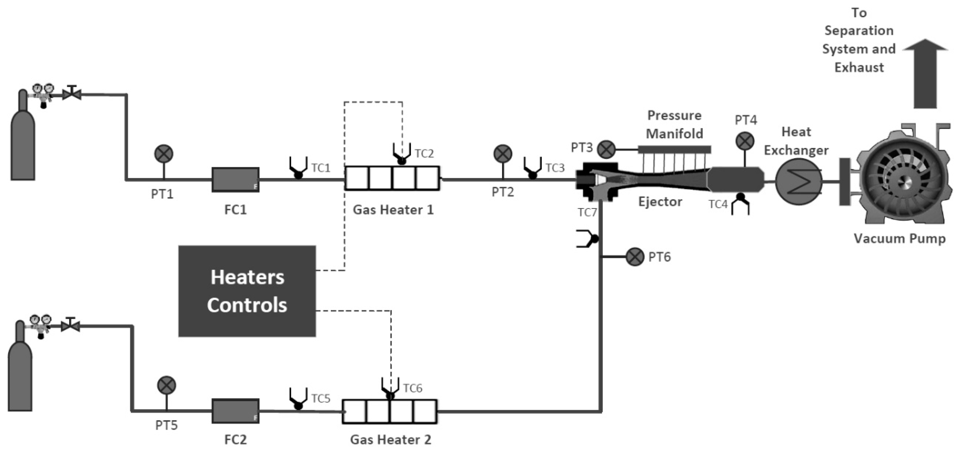
Figure 1 illustrates the schematic diagram of the experimental setup. The testing system for inert gases included gas bottles equipped with pressure regulators and needle valves to ensure precise pressure control. Additionally, the system included electric circulation heaters with PID controllers, a configurable ejector with an attached pressure manifold, a vacuum pump (liquid sealed with silencer/separator) and a heat exchanger. All of the flow components and heaters were covered with ceramic and fiberglass insulation.
For temperature measurements, a total of seven type K thermocouples (labeled TC1–TC7) were used. Thermocouples were calibrated using a reference probe with a reference junction, a thermocouple calibration furnace and a high-precision temperature scanner. All uncertainties (measurement noise, readout accuracy of reference probe, reference probe calibration uncertainty and long-term drift, furnace axial and radial uniformities) were combined using root sum squares (RSSs). A coverage factor of k = 2 was used in these calculations (which corresponds to a 95% confidence interval). At 500 °C (max. heat temperature), the expanded uncertainty was evaluated as being 0.5 °C. To measure pressure at different points within the system, six absolute static pressure transducers (labeled PT1–PT6) were used. The static error band was utilized as a means of assessing the expected accuracy of a pressure sensor operating under constant temperature conditions. It is expressed as a percentage of the sensor’s full range (span), denoted by a ± value, and is relative to the best straight line (BSL). The pressure transducers used were OMEGA PX309-300A5V (range: 0–300 psia, static accuracy (combined effects of linearity, hysteresis and repeatability): ±0.25% BSL, maximum) for PT1 and PT2, OMEGA PX409-005AV (range: 0–5 psia, static accuracy (combined effects of linearity, hysteresis and repeatability): ±0.08% BSL, maximum) for PT3, OMEGA PX309-015A5V (range: 0–15 psia, static accuracy (combined effects of linearity, hysteresis and repeatability): ±0.25% BSL, maximum) for PT4 and OMEGA PX309-005A5V (range: 0–5 psia, static accuracy (combined effects of linearity, hysteresis and repeatability): ±0.25% BSL, maximum) for PT5 and PT6. Two OMEGA FMA5544ST Mass Flow Controllers labeled FC1 and FC2, with a range of 0–500 standard L/min and an accuracy of 0–20% range ±3%FS for the lower range and 20–100% range ±1.5% FS for the upper range, were used for flow rate measurements and control. The programming language used was National Instruments LabVIEW. The thermocouples were positioned 2 inches away from the inlets and outlet of the ejector, while the pressure sensors were located 4 inches away from the ejector’s inlets and outlet. To validate the CFD models, a configurable ejector was constructed using the Engineering Sciences Data Unit (ESDU) recommendations: ESDU 86030 [
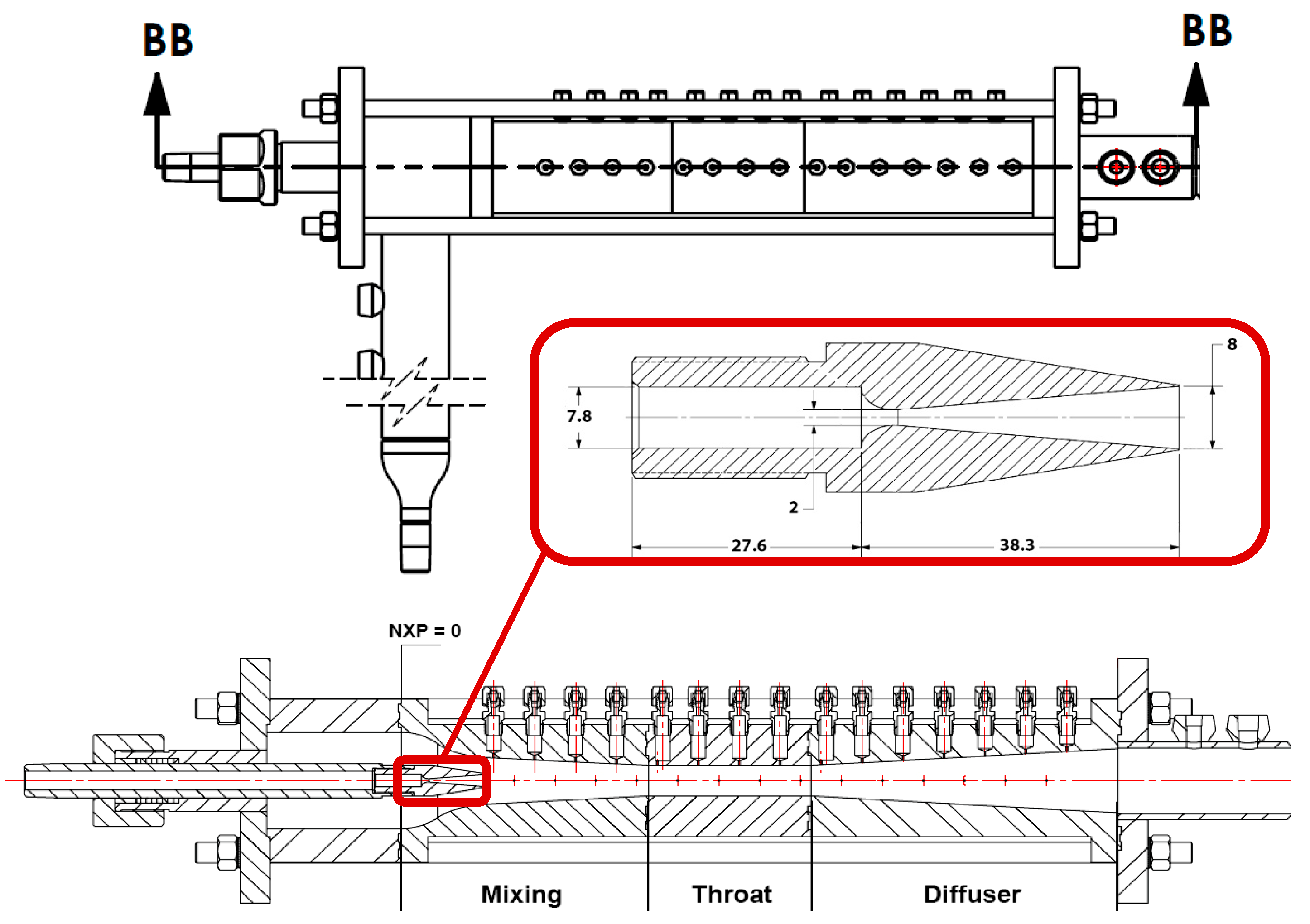
18]. ESDU 86030 provides systematic calculation methods, utilizing performance charts, to facilitate the optimal design of steam/liquid and steam/gas ejectors. Additionally, the document outlines the mechanical design considerations for various components such as the primary nozzle, mixing chamber and contraction or diffuser. The ejector offers adaptable geometry control and the ability to reposition the nozzle within it. The ejector consists of four primary components: the nozzle, mixing chamber, throat and diffuser.
The mixing chamber length was 145 mm, the throat length was 95 mm and the diffuser length was 180 mm. The throat had a diameter of 19 mm, and the diffuser’s inlet diameter and outlet diameter were 19 mm and 40 mm, respectively. The diameter of the mixing chamber’s inlet diameter was 29 mm. Twenty-nine pressure ports were installed along the ejector body for static pressure measurements. The detailed nozzle geometry is shown in
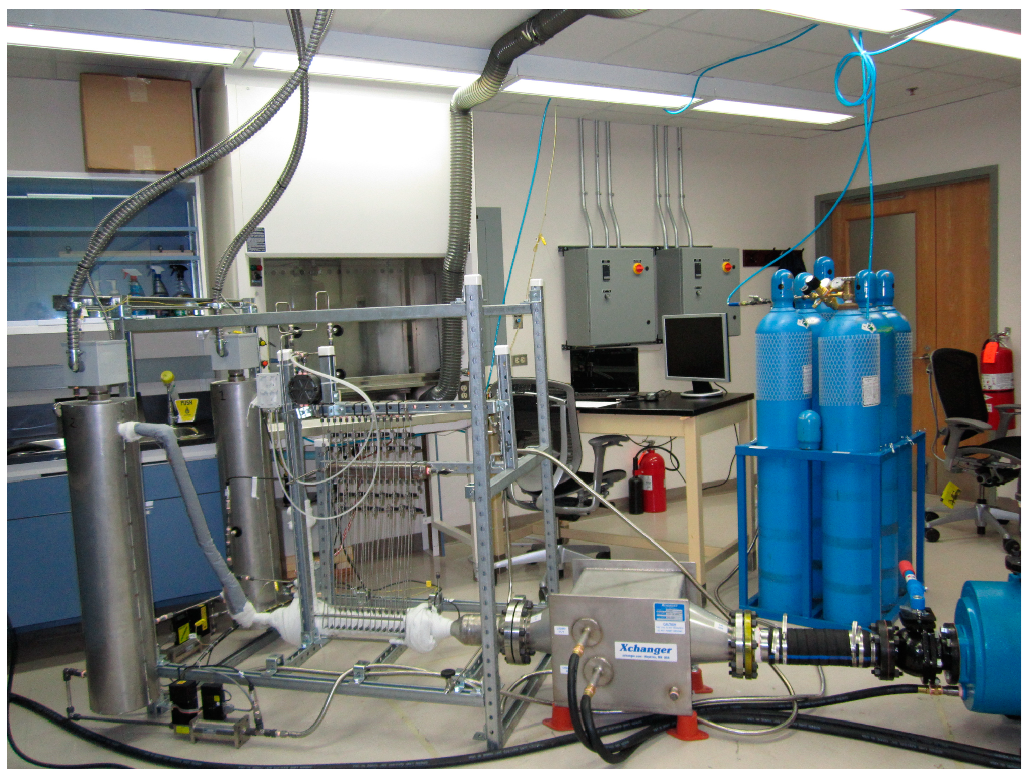
Figure 2. The nozzle exit position (NXP) is defined as the distance between the nozzle exit plane and the mixing chamber inlet plane, and it was fixed at 35 mm. The primary objective of this paper was to maintain this configuration, along with fixed inlet and outlet pressure, and investigate the resulting ejector operation and flow dynamics. The only variable being altered was the inert gas, with different gases utilized for primary and secondary flow. The experimental setup is shown in
Figure 3.
3. Experimental Procedures
In this study, two pairs of inert gases were tested: argon–helium and krypton–air. The primary and secondary flows were maintained at specific flow conditions, as follows: a temperature of 200 °C for the primary flow, a temperature of 50 °C for the secondary flow, primary flow pressure of 0.9 MPa, secondary flow pressure of 10 kPa and pressure at the ejector exit of 15 kPa. These pressures were regulated through a system of valves, pressure regulators and a vacuum pump. Initially, the vacuum pump was activated, and then the primary line was opened, with the primary pressure being adjusted using the pressure regulator and needle valve for fine tuning. Then, the secondary flow was regulated using a second pressure regulator and needle valve. While both lines were active, the nozzle pressure (PT2), secondary line pressure (PT6) and ejector exit pressure (PT4) were adjusted, until reaching given pressure operating conditions. To establish the temperature regime, two PID controllers were used in conjunction with thermocouples TC2 and TC6. The optimal parameters (proportional, integral and derivative) were defined for this set of experiments. The usual time of temperature stabilization was about 6 min. The temperature was monitored using LabVIEW software until stable temperatures were attained in both the primary and secondary lines. Throughout this process, slight adjustments were made to the pressure to account for temperature fluctuations and maintain the designated pressure regime described above. Subsequently, static pressure along the ejector’s wall was recorded using a pressure manifold. Each port was opened sequentially, and pressure values were recorded after they had stabilized.
4. CFD Model
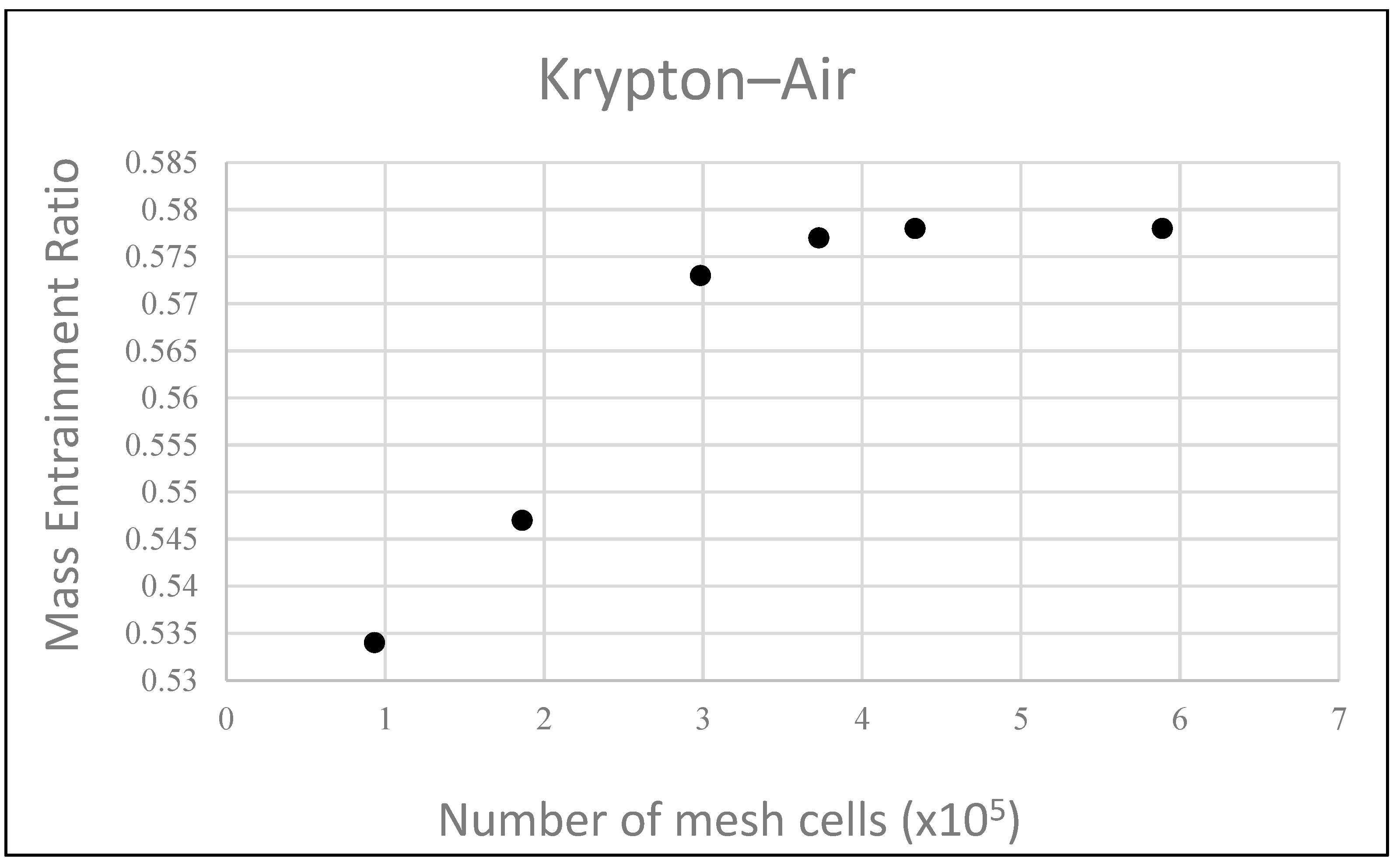
In this study, ANSYS FLUENT 18 was used to solve a two-dimensional axisymmetric problem. A mesh independence study was conducted, where the mesh was divided into regions and refined near walls, in the shear layer and around shock waves. The optimal number of cells for CFD analysis was determined to be between 373,000 and 434,000. The grid independence study was performed using the mass entrainment ratio for the krypton–air case (
Figure 4).
The system of governing equations was solved using density-based and implicit methods, with a second-order upwind scheme employed for the spatial discretization of convective terms and the QUICK method used for the turbulent equations coupled with the energy equation. Various RANS turbulence models were studied, and it was found that the SST k-ω model provided the best agreement with experimental values for entrainment ratios across a wider range of operating conditions and geometries. The following equations of the turbulence model were used in this study [
19,
20,
21,
22]:
In these equations, represents the generation of turbulence kinetic energy due to mean velocity gradients, represents the generation of ω, and and represent the effective diffusivity of k and ω, respectively. and represent the dissipation of k and ω due to turbulence. represents the cross-diffusion term. and are user-defined source terms.
Pressure inlet boundary conditions were set at the primary and secondary fluid entrances, with a pressure outlet at the diffuser exit. The temperature for the primary flow was 200 °C, and that of the secondary flow was 50 °C. Convergence was determined when the residual for each governing equation was less than 10
−6. The mesh structure and the boundary conditions are shown in
Figure 5.
5. Results and Discussion
Figure 6 and
Table 1 illustrate the comparison between the experimental results and the CFD predictions. It can be seen that the SST k-ω model gives a good prediction of the static pressure distribution along the ejector wall and a good prediction of the exit temperature and entrainment ratio. It should be noted that the SST k-ω model provides a better prediction of the static pressure distribution for larger differences in molecular weight between the working fluids then in [
5]. This could be related to the higher molecular diffusion rates that exist for fluid pairs with a small difference in molecular mass. Indeed, the SST k-ω model primarily focuses on capturing turbulent transport phenomena and may not adequately account for the influence of molecular diffusion.
Two cases were considered in this study for the pairs of inert gases with a significant difference in molar mass. In the first case, primary fluid molar mass was significantly increased by utilizing krypton (83.798 g/mol); in the second case, argon was used as the primary gas (molar mass: 39.948 g/mol) and the molar mass of the secondary gas was significantly decreased by utilizing helium (4.0026 g/mol).
Table 1 shows that the mass entrainment ratio was significantly lower for the argon–helium case.
The molar entrainment ratio accounts for the molar mass of the secondary fluid being entrained, and it affects the density and specific volume of the fluid mixture, which in turn influence its compressibility and thermodynamic properties. By considering the molar entrainment ratio, the impact of different gases with varying molecular weights on the ejector’s performance could be evaluated more accurately. In certain ejector applications, such as steam ejectors or gas ejectors, the entrainment of fluids with different molar masses might significantly affect the flow dynamics, pressure recovery and overall efficiency. The molar entrainment ratio could provide a deeper understanding of these effects and allow for a more comprehensive assessment of the ejector’s performance. Both the mass entrainment ratio and the molar entrainment ratio are important for evaluating the performance of an ejector. The mass entrainment ratio reflects the quantity of entrained secondary fluid, while the molar entrainment ratio considers the molar mass of the entrained fluid, accounting for its thermodynamic properties and its influence on the overall system behavior. Furthermore, as was shown in [
5], the COP is proportional to the mass entrainment ratio:
where
w is the mass entrainment ratio and
fh is the ratio of the evaporator over the boiler enthalpies (if pump energy is being neglected). Therefore, the outcomes of the present study can be useful in refrigerant selection for practical applications. Further analysis on the effect of other system energy exchanges on the system COP was discussed in [
15,
22].
It can be seen from
Table 1 that the molar entrainment ratio is higher in the case of argon–helium compared to krypton–air, whereas the mass entrainment ratio is higher in the case of krypton–air. There could be several potential practical applications of this result, for example, in combustion or chemical reactors, where the composition of the gas mixture significantly affects the process outcomes. By utilizing higher molar entrainment with lower mass entrainment, it could be possible to precisely control the molar composition of the mixture, allowing for targeted gas mixing and achieving specific reaction conditions. Moreover, in gas separation processes, such as distillation or absorption by optimizing molar entrainment, it might be possible to selectively entrain gases with desired properties or components, enabling the efficient separation of the gas mixture. Higher molar entrainment can provide better selectivity in separating specific components based on their molar composition.
Figure 7 displays the Mach number distribution within the ejector for the two studied cases, where Mach number iso-values lower than one were omitted to emphasize the supersonic core’s boundaries. The findings reveal a noticeable decrease in the supersonic core expansion within the ejector throat for the argon–helium case when compared to krypton–air. Moreover, a flow blockage is apparent in the krypton–air pair inside the ejector throat, which is also shown in the wall pressure profile (
Figure 6) as a pressure drop at the throat exit. Additionally, oblique shockwaves can be observed in the diffuser for both cases.
Figure 8 shows that the wall shear stress (WSS) profile (obtained from the CFD simulations) exhibits two peaks in the krypton–air case, with one located at the throat inlet and the other located at the throat outlet. The initial peak corresponds to the contraction that occurs during the transition from the mixing chamber to the throat, where the fluids accelerate. The second peak is related to flow blockage and separation and correlates with the static pressure drop along the wall (
Figure 6). In the case of argon–helium, only the first WSS peak is observed at the throat inlet since there is no flow separation or blockage, which allows the supersonic core to travel freely to the diffuser without any contact with the walls. This can also explain the absence of a sharp pressure drop that was observed for the krypton–air case (
Figure 6). It should also be noted that the wall shear stress plateau presents a higher magnitude for the krypton–air case.
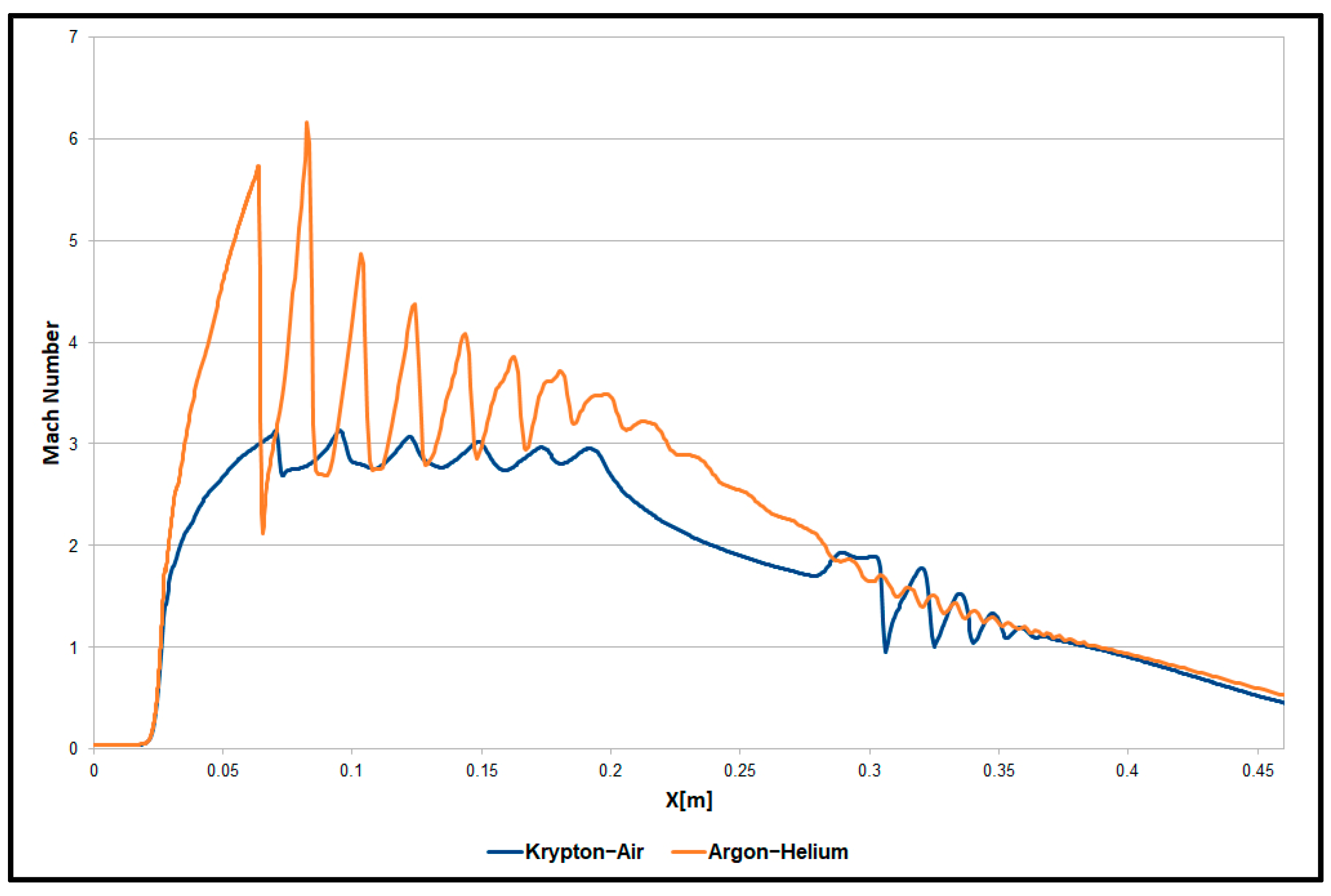
Figure 9 displays the Mach number profiles along the ejector centerline to demonstrate the quantitative variation in the Mach number distribution. It can be seen that the supersonic core length is the same in both cases; however, the argon–helium case exhibits considerably higher Mach numbers, which can be attributed to the notable increase in krypton’s density. This leads to stronger shock waves and subsequently less mixing between the primary and secondary fluids, which can be seen from the entrainment ratio in
Table 1.
Figure 9 also shows that the argon–helium case shows significantly stronger fluctuations in Mach number distribution along the mixing chamber centerline, which indicate the presence of strong shockwaves in this region. In contrast, the krypton–air case displays a more intense sequence of oblique shockwaves inside the diffuser.
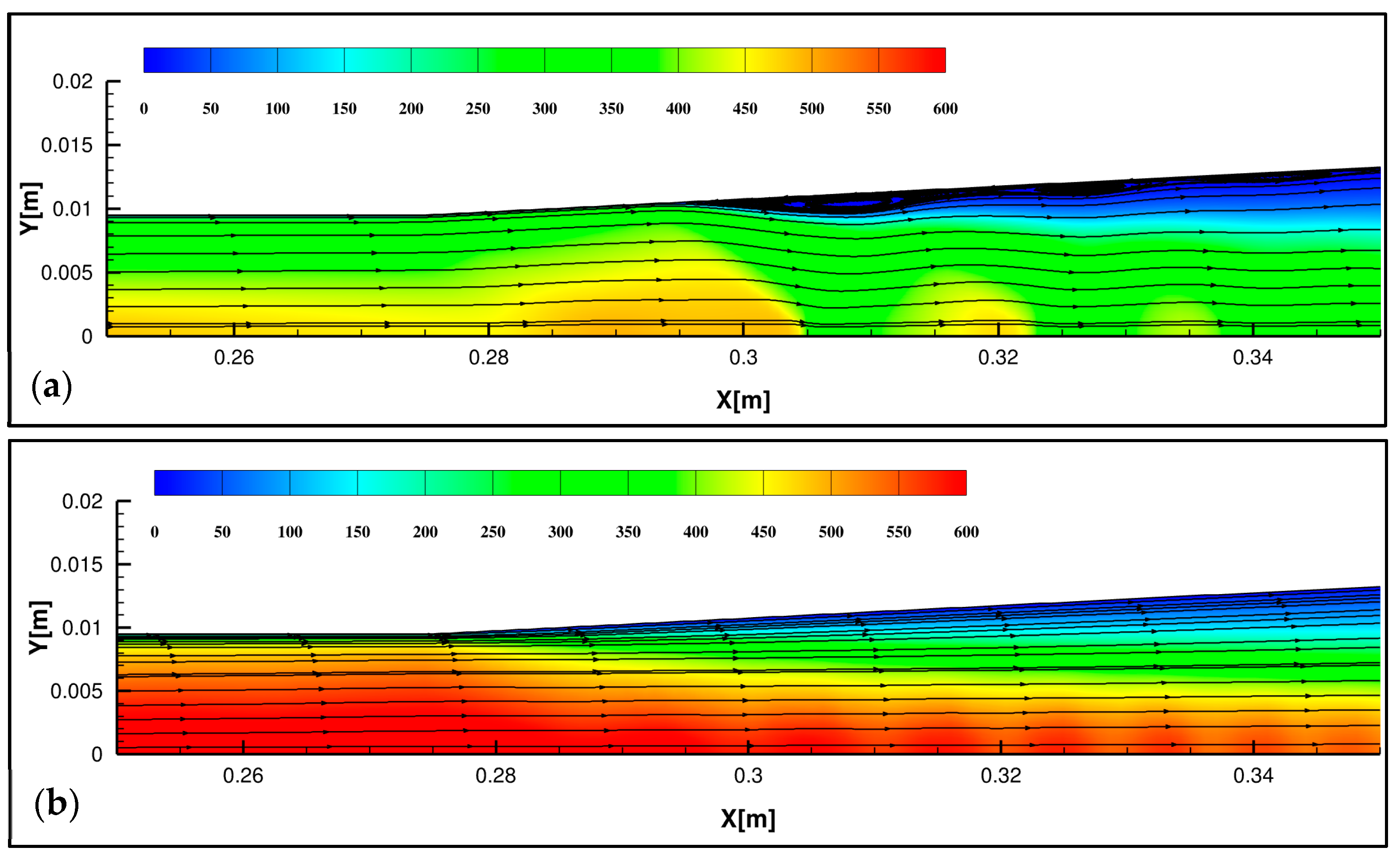
Further details about the flow dynamics around the diffuser inlet are shown in
Figure 10. It is shown that small recirculation zones are observed along the diffuser wall for the krypton–air case. It is worth noting that the observed flow recirculation near the diffuser inlet has a negligible effect on the ejector’s performance. However, substantial recirculation zones can significantly impact the ejector’s performance, as reported in previous studies [
23,
24]; recirculation regions were not observed in the case of argon–helium.
6. Conclusions
CFD modeling was used in the present study to investigate the flow dynamics inside a supersonic gas–gas ejector with two different inert gas combinations. The experimental results were used to validate the numerical prediction of the entrainment ratio and static pressure. The main objective was to compare the ejector performance and flow structure between krypton–air and argon–helium combinations with a significant difference in molar mass.
The wall static pressure was well predicted along the ejector wall in both cases. It is interesting to note that the SST k-ω model made a better wall pressure prediction for the pairs of inert gases with a significantly higher difference in molar mass than in [
5].
This study revealed that the molar entrainment ratio was notably greater in argon–helium than in krypton–air, with a 75% increase. Conversely, the mass entrainment ratio was substantially higher in the case of krypton–air. The potential applications of this outcome were discussed in the present paper.
The wall shear stress (WSS) profiles showed distinct characteristics in the krypton–air and argon–helium cases. This led to a better understanding of the flow dynamics inside the ejector. This was particularly the case for the krypton–air case, characterized by a flow blockage inside the ejector throat and flow separations near the diffuser inlet.
Finally, the Mach number distribution along the ejector centerline revealed that the centerline of the argon–helium case exhibited stronger shockwaves inside the mixing chamber, whereas the krypton–air case showed a more intense sequence of oblique shockwaves inside the diffuser.


