1. Introduction
Compared to internal combustion engines, electric motors have a higher speed rating range and a wider and more efficient operating zone [
1,
2]. However, the advantages of electric motors are not fully utilized due to the speed limitation of hydraulic pumps in the hydraulic system. Since electric motors will be more widely used in the era of mobile machinery electrification where the carbon emissions are strictly limited, high efficiency and energy saving become important aspects of the innovative development of electro-hydraulic power units. In such a context, opportunities and challenges will emerge simultaneously for high-speed design of hydraulic pumps [
3].
Gear pumps, belonging to the group of gear displacement machines, can be found in internal combustion engines, circulating lubrication systems, fuel systems, etc. At present, high-speed hydraulic pumps are basically focused on the development of aviation piston pumps [
4,
5]; the civil equipment has not yet seen widely used reports. A new type of circular arc gear pump with high speed is in the research stage [
6]. Crescent-type internal gear pumps (CIGPs) make a power source of the most commonly used fluid power applications due to their simple construction, compactness, high volumetric efficiency, and low noise level [
7]. As a result of these advantages, the recent trend towards electrification in many sectors of the hydraulic field is driving the development of CIGP designs as one of the best choices for integration with electric motors.
The diagram of a CIGP is schematically presented in
Figure 1. A crescent sealing fixed between a pinion gear and a ring gear makes the high- and low-pressure chambers within the inter-teeth volume free from each other, and they can be interchanged depending on the direction of rotation due to the symmetric structure. As the pinion gear and the ring gear rotate around O
1 and O
2, respectively, the working fluid in the low-pressure chamber will be carried into the high, subsequently being squeezed out with energy as the gears continue to mesh.
More and more scholars and companies are carrying out a lot of research work on the design of CIGPs. The speed range of QXEHX series pumps developed by Bucher Hydraulic Inc has now been extended up to 5000 rpm. Increased power density and high operational reliability make QXEHX pumps particularly suitable for downsizing the entire drive train, e.g., in injection molding and die-casting machines. Unfortunately, the technical information is not yet publicly available.
There are many reasons for the reduction of the effective oil delivery of a hydraulic pump. Rafał and Mykola demonstrated the pump deformations on circumferential gap height as a factor influencing volumetric efficiency [
8]. Therefore, regardless of high-speed or high-pressure conditions, if low-viscosity liquids were to be used, the axial and radial clearances between the gear pair and the housing should be reduced to avoid large internal leakage [
9].
However, insufficient oil suction caused by cavitation is one of the shared problems that limit the operation of hydraulic pumps at high speeds [
10,
11,
12]. Numerous scholars have dedicated themselves to solving this issue, and analysis of the literature shows that the work can be conducted in two different directions. The first one mainly focuses on the detailed design and optimization of the structure of the hydraulic pump, the aims of which are reducing the resistance to oil flow and eliminating cavitation phenomena. Stryczek and Antoniak designed a new type of relief groove in the gear teeth, and the results of the visualization experiment demonstrated a considerable reduction of the cavitation phenomena in the outlet and inlet chamber zone of the external gear pump [
13,
14]. The main geometric parameters of the gerotor pump, including the thickness and the diameter of the gear pair, the position of the inlet pipe, and the shape of the port plate influencing the suction capacity, were analyzed in detail. As a result of the analysis, the principles of designing the pumps with efficient oil suction have been finally specified [
15]. Chao invented inward-inclined ports on the cylinder block of a piston pump that can increase the delivery flow rate by 4% compared with a standard one [
16].
The second direction of the research is in increasing the pressure of the suction chamber of the hydraulic pump by the means of an auxiliary pressure booster, which is considered to be the most effective method [
17,
18]. A kind of piston pump with an integrated centrifugal impeller has made a major breakthrough in aviation applications [
19,
20], such as the high-speed piston pump (V30G) generated by the German company InLine; Bosch Rexroth (A15VLO) and Danfoss Hydraulic (D1P) have also offered similar products.
Another instance of this trend was reported in paper [
21], in which a hollow shaft centrifugal pump structure was designed by trying to determine the characteristics of pressure change in the suction chamber of the displacement pumps. Fortunately, the experimental and simulation results validated the feasibility of this solution.
This work adds fresh content for the aforementioned directions, in which the CIGPs were taken as the subject of study. The geometric parameters of the gear pair more suitable for high-speed operation were first calculated and analyzed. Then, to improve the suction capacity, three non-positive displacement pumps (N-PDPs: inclined-holes type, axial-flow blades type, and centrifugal impeller type) were proposed, and the performance of each was evaluated in terms of the filling efficiency of CIGPs. In the compact design solution, the gear pump part was designed as a cartridge kit assembly considering the convenience of installation and repair.
In the present study, all computational fluid dynamic models and simulation calculations were carried out with the commercial software PumpLinx, a specialized software for predicting the theoretical performance of the pumps, the calculation results and accuracy of which have been proven reliable by numerous cases [
10,
15,
21,
22].
2. Suction Capacity of CIGPs
The CIGPs can be designed with different geometric morphologies as far as the same displacement is concerned.
Figure 2 shows structural dimensions of gear pairs with different modulus, in which the teeth numbers of the pinion gear and ring gear are 10 and 13, respectively, as well as the same profile half-angle with a value of 27.3°. It is clear from
Figure 2 that the larger the modulus, the larger the radial dimension of the gear pair. Then, to ensure the same displacement, the axial dimension needs to be reduced accordingly.
Often, in engineering calculations, an approximate formula (see Equation (1)) is used to obtain the gear pump displacement, which is based on the assumption that the working volume between the teeth is equal to the effective volume of the gear teeth. Then, the displacement per revolution of the gear pump is equal to the sum of the working volume between all the teeth of the pinion gear and the effective volume of all the gear teeth. That is, the required displacement is equal to the volume of the annular cylinder between the tip circle and the root circle of the pinion gear.
where
Rf and
Ra denote the tip circle radius and root circle radius of the pinion gear (see in
Table 1), respectively. The results of theoretical calculations with different moduli are listed in
Table 1.
Here, the filling efficiency is defined as the ratio of the average volume flow rate obtained from the simulation to the theoretical value, i.e.,
where
η denotes the filling efficiency,
QA (L/min) is the monitored average flow rate at the outlet of the simulation model or is obtained from flow meter tests in the test bed,
QT (L/min) indicates the theoretical value, and
n stands for the considered rotational speed.
To identify which gear pair is more suitable for high-speed operation from the point of view of filling capacity, conducting the internal flow field simulation is necessary. Modeling and meshing can be performed easily and quickly with the help of the specialized software PumpLinx (V4.6.0).
In the present study, the ReNormalizattion Group (RNG) k-ε turbulence model [
23] and cavitation model (constant gas mass fraction) provided by PumpLinx were used to accurately simulate the characteristics of CIGPs [
24]. The standard wall function was chosen to simulate the near-wall behavior of the fluid. The pressure velocity coupling method selected SIMPLEC, while the convection term was discretized in second-order upwind. The fluid properties and simulation conditions are listed in
Table 2.
Before further simulation analysis, the mesh sensitivity was carried out using modulus 4.5 as an example. The variation of the average volume flow rate at 6000 rpm with the mesh number is listed in
Table 3. It can be found that the average volume flow rate of CIGPs tends to stabilize when the cell number exceeds 150,000. Therefore, the number of meshes for the simulation models in the subsequent section is set at about 150,000.
Moreover, in order to verify the validity of the simulation model mentioned above, a test bed was built, as shown in
Figure 3a. A permanent magnet synchronous motor was used to drive the CIGP, the speed of which was regulated by a frequency converter (not shown in the test bed). Only 2.14% maximum data deviation between the simulation and experiment in the 600~6000 rpm range was detected, as shown in
Figure 3b. It is important to note that the pump tested has the same parameters as the simulation model. Therefore, the PumpLinx software can be used to predict the effective output flow of the CIGP more accurately, and can further analyze the reasons for the reduction in flow rate.
As shown in
Figure 4, the internal flow field models and meshes of CIGPs with moduli of 3, 4, 4.5, and 5 are included, where the inlet and outlet dimensions are kept consistent with values of 30 mm and 19 mm, respectively. Since the rotational speed is the key parameter to be studied, in order to simplify the calculation, the internal leakages of CIGPs were not taken into account in the present study.
Combining Equations (1)–(3), the calculated results were plotted as curves shown in
Figure 5.
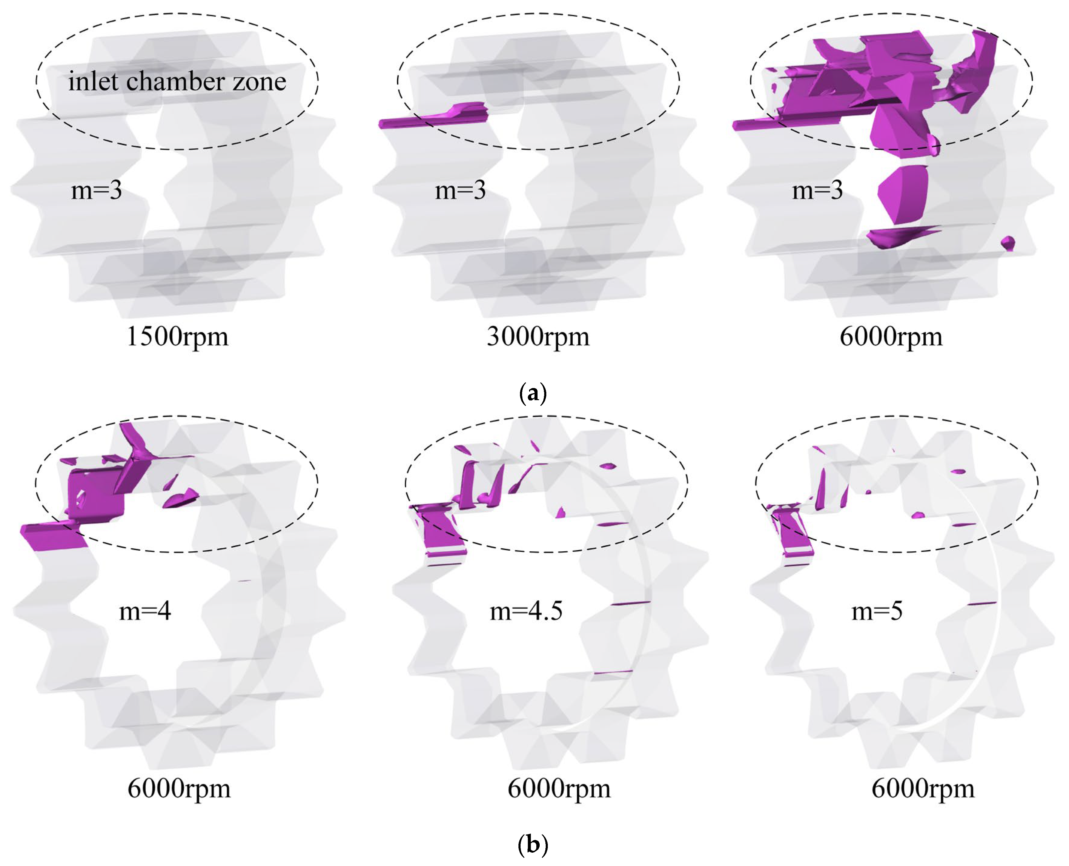
It is observed that the filling efficiency of CIGPs shows a decreasing trend. By comparison, modulus 3 has a faster drop rate, and the flow rate saturation phenomenon tends to occur, caused by serious incomplete filling at 6000 rpm, while the other three can still maintain their filling efficiency above 90% in a wide range of speeds. Two main reasons can be summarized to explain this phenomenon. On one hand, the axial dimension of the gear pair of modulus 3 is longer, which means a slender-type suction chamber. In such a case, the working fluid is forced by the pinion gear to the discharge chamber before it is fully filled with the suction port, and consequently there is insufficient filling. On the other hand, it is presumed to be caused by cavitation. To confirm this speculation, the distribution area of gas volume fraction higher than 0.5 was extracted as shown in
Figure 6.
As the rotational speed raises from 1500 rpm to 6000 rpm, the gas (the volume fraction > 0.5, see
Figure 6a) in the fluid domain gradually goes from nothing to almost filling the entire inlet chamber zone, which explains very well why flow saturation occurs. Whereas a delightful observation emerges from the comparison, as shown in
Figure 6b. The gas content in the fluid domain of the short-thick type gear pair is relatively much lower, and the gas volume fraction in modulus 4.5 and 5 is approximately the same at 6000 rpm, as well as the filling efficiency (see
Figure 5). Therefore, in the following study, a CIGP model with modulus 4.5 was chosen as the reference.
In order to further define the suction characteristics of high-speed CIGPs, a general CIGP (rate speed: 2000 rpm) model was developed as a case for comparative analysis, the geometric displacement of which is 30.45 mL/r. It is noted that the only difference between the two models is the axial length of the gear pair.
Figure 7 presents the simulation results for four flow-rate specifications; as expected, the required flow rate can be output using both pumps. Moreover, the high-speed CIGP has the advantage of higher filling efficiency in the first three grades, while the fourth is what needs to be addressed below. In addition, the gear pair can be designed into a short and thick structure to reduce the axial dimension, which is not discussed in detail in this paper.
3. Pairing Solutions of CIGPs and N-PDPs
As in the previous analysis, at high speed, the self-suction ability of the CIGP alone cannot guarantee its volumetric efficiency as much as conventional speed, therefore, an auxiliary suction device is very necessary. Here, three auxiliary methods aimed at increasing the suction port pressure of the positive displacement pump are proposed.
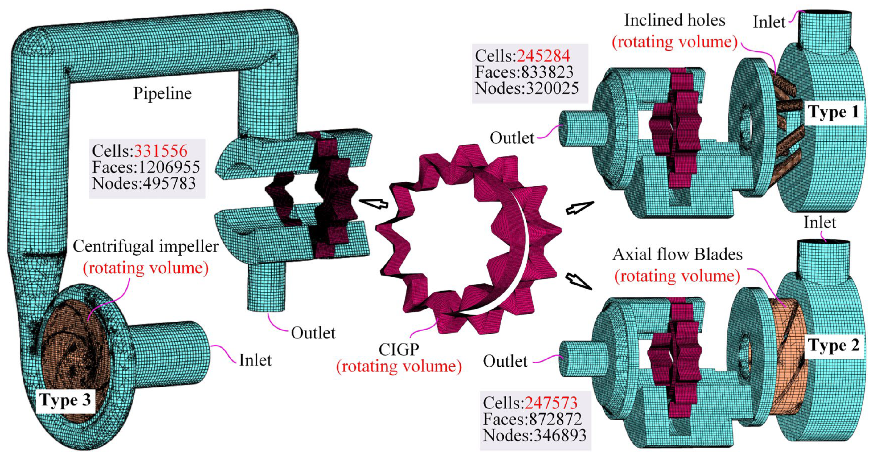
Figure 8 presents the structural schematic of a novel design of a high-speed CIGP with an integrated N-PDP booster, where a centrifugal-holes type or an axial-flow blade type is proposed to be integrated with a CIGP.
The oil is forced directly into the suction chamber of the CIGP as soon as it flows through the centrifugal holes or axial-flow blades. In this design, the shafts of the N-PDP and CIGP were integrated as one, i.e., the two coaxially share the same speed, in which the shaft and the pinion gear are coupled by the spline. Even better, in addition to being compact, only one drive motor is needed. Since the gear pair is a vulnerable part, especially at high speed, a CIGP cartridge kit was proposed, as shown in
Figure 9. The structural features can be summarized as follows: (1) The crescent plate is set on the low-pressure cover, thus the outwardly convex structure is easy to process and surface strengthen. (2) The axial friction sub-gap is not fixed and is controlled by the stator ring. (3) Repair costs are greatly reduced by simply replacing damaged parts. (4) The coaxiality of the cartridge kit is determined by the accuracy of the installation process.
Figure 10 gives the third option, which is more flexible in the handling of speed matching as well as the space layout, yet the centrifugal oil pump requires an additional motor drive. In this way, the operating speed of the auxiliary pump can be dynamically adjusted to match the flow rate required by the hydraulic pump. From another point of view, the speed of the centrifugal impeller can be increased, so that its structural dimensions can be designed to be smaller. The outlet of the centrifugal oil pump is connected to the CIGP inlet using a rubber hose with a flange.
In order to evaluate the feasibility of the three type solutions, the full flow field calculation models of the N-PDPs and CIGPs in series were established, as shown in
Figure 11. It should be noted that the rotating volume of the CIGP model involved in the full flow field models was the same one (modulus is 4.5), which was meshed by a crescent template provided by PumpLinx. Furthermore, the diameter of the inlet and outlet, as well as the boundary and operation conditions, were set the same (see
Table 2).
4. Results and Discussion
A large number of simulations at different speeds were calculated by using the full flow field models mentioned above.
Figure 12 presents the pressure distribution and gas volume fraction distribution in the rotating volume of the CIGP at 6000 rpm. A noticeable feature is that the high-pressure (≥101.325 kPa) area of the suction port cross-section increases in types 1 and 3, compared to the conventional one under the same conditions, while no pronounced change is seen in type 2. As a result, the cavitation phenomena have not been effectively eliminated but rather made worse. Among the three solutions, the third shows the most significant pressurization effect and, as a consequence of it, the weakest cavitation level.
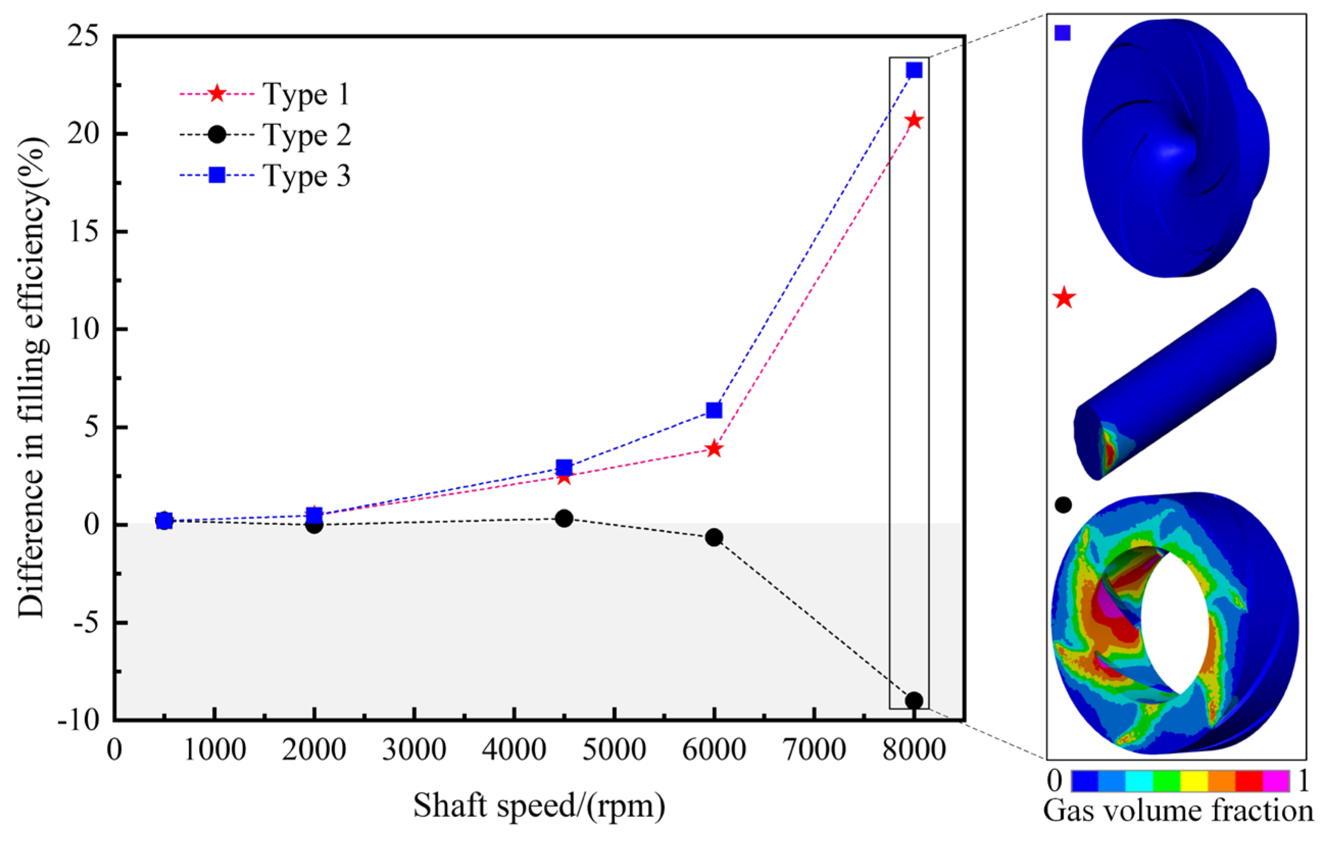
The pressurization effect is directly manifested in the variation of filling efficiency, as shown by the different filling efficiency curves with a common CIGP (see
Figure 13) when N-PDPs share the same speed with CIGPs. As expected, the pressurization effect of type 2 presents as unsatisfactory over a wide speed range, and a serious side effect occurs at 8000 rpm. The reason for this phenomenon is that the fluid domain in the axial-flow blades also undergoes cavitation. However, it is promising that the pressurization effect of the other two types is enhanced with increasing speed. The filling efficiency of the CIGP can be increased by 5.84% and 3.89% at 6000 rpm, respectively. Although type 1 is slightly less effective, it provides a new idea in compact design, where efficiency can be sacrificed a little bit. The filling efficiency at low speeds (≤2000 rpm) is almost the same as that of the conventional pump, which means that the N-PDPs at low speeds do not prevent the CIGP from sucking oil.
In decentralized solutions, the speed of the centrifugal pump can be adjusted to maximize compensation for the filling efficiency of the CIGP.
Figure 14 gives filling efficiency as a function of the rotation speed of the centrifugal pump when the CIGP works at a constant speed of 6000 rpm.
Figure 14 is divided into two zones, in which the “Impeding effect” zone refers to the centrifugal pump speed being too low to impede the oil flow, while the CIGP always has a higher filling efficiency than the conventional one in the “Beneficial effect” zone. Therefore, it is recommended that the operating speed of the centrifugal pump should not be lower than 2500 rpm. Increasing the speed of the centrifugal pump may increase the energy loss and noise, which requires further experimental studies.
5. Conclusions and Future Work
The presented research has proved the feasibility of a high-speed crescent-type internal gear pump (CIGP) paired with a non-positive displacement pump (N-PDP) to pressurize its inlet to prevent serious cavitating. For different application conditions, two solutions were proposed: compact design and decentralized layout. The following conclusions can be drawn based on the simulation results presented in the present study:
- (1)
For the same displacement, the flow rate saturation phenomenon tends to occur in CIGPs with small moduli due to insufficient filling at a higher speed than specified. This is due to the fact that the pinion gear forces the working fluid to the discharge chamber before it is totally filled with the suction port of the CIGP. In addition, cavitation appearing in the fluid domain of the suction chamber is the main culprit.
- (2)
For the same output flow rate grade, the high-speed CIGP not only has advantages in structure size, but also has a higher filling efficiency over a wide range of speeds compared to the conventional hydraulic pump. Certainly, this is not always the case, the filling efficiency is relatively low at 6000 rpm.
- (3)
In the compact design solution, the inclined-holes type N-PDP takes advantage of the centrifugal effect of forcing fluid into the suction port of the CIGP to eliminate cavitation, and the higher the speed, the better the effect. Compared with the standard CIGP, this novel design increases the filling efficiency of the CIGP by 3.89% when the rotational speed is 6000 rpm, while the axial-flow blades type N-PDP shows a serious side effect due to the cavitation occurring by itself.
- (4)
In the decentralized layout solution, a centrifugal impeller type N-PDP was designed to pair with a standard CIGP. When both working speeds are the same, the filling efficiency of a standard CIGP always keeps an increasing trend with the increase of working speed, and the filling efficiency can be improved by 5.84% at 6000 rpm. However, when the CIGP works at 6000 rpm, the speed of the centrifugal impeller needs to be kept above 2500 rpm, otherwise, it will impede the CIGP from sucking oil instead.
In the present study, two effective solutions were offered to pressurize the inlet of a CIGP to keep it from cavitating, which have been verified numerically. The outcomes from this paper can be used as a reference for maximizing the filling capability of all kinds of hydraulic pumps at high speed. Of course, it is certain that the prototype cannot be manufactured by considering the filling efficiency alone, since additional energy loss and noise may tend to occur. Future work will focus on solving the friction and wear of friction pairs, rotary seal failure, etc. Ultimately, problems will be identified and solved from prototype experiments.


