

Experimental Demonstration of Compact Polymer Mass Transfer Device Manufactured by Additive Manufacturing with Hydrogel Integration to Bio-Mimic the Liver Functions
 , ,
, ,
Abstract
:
1. Introduction
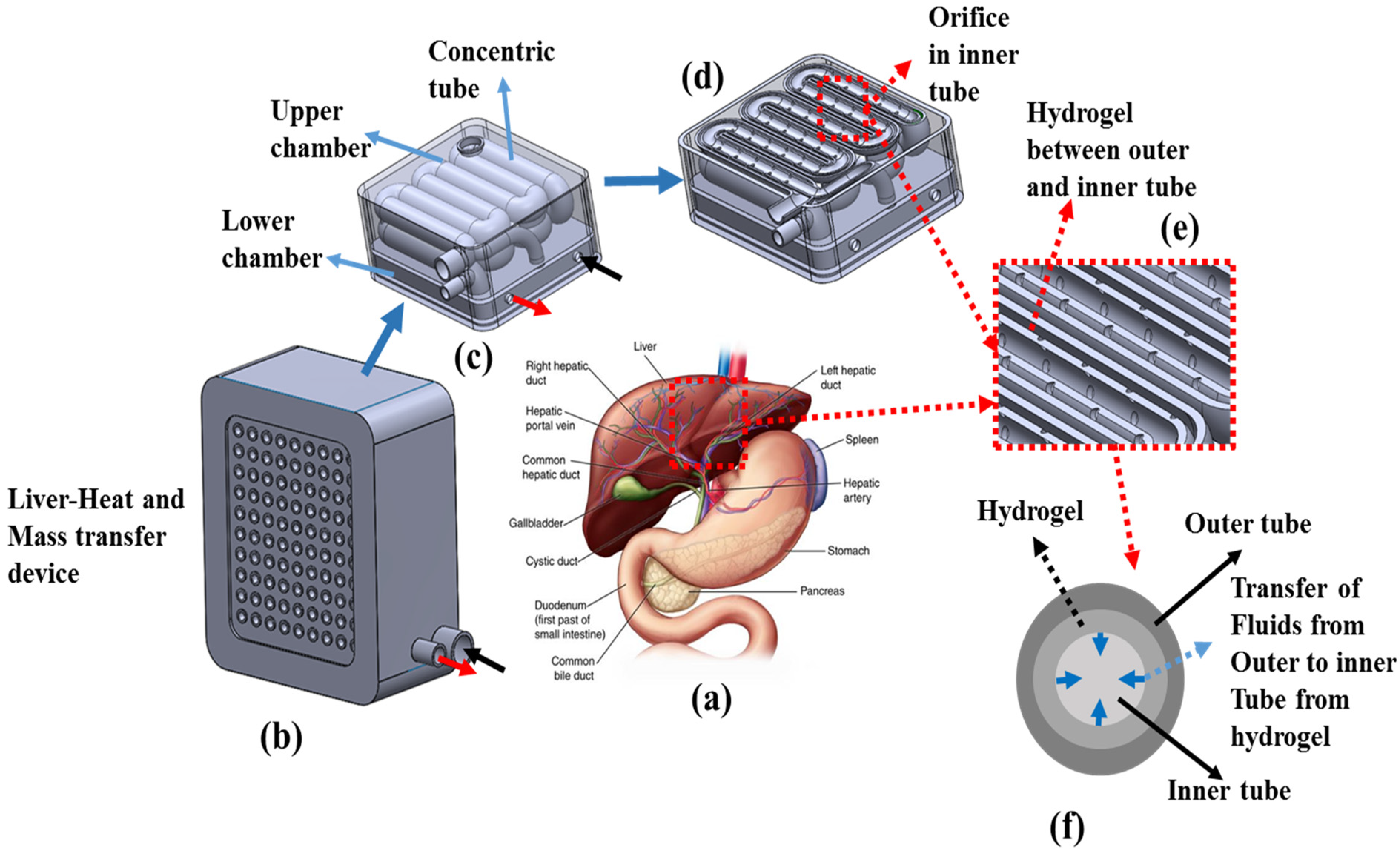
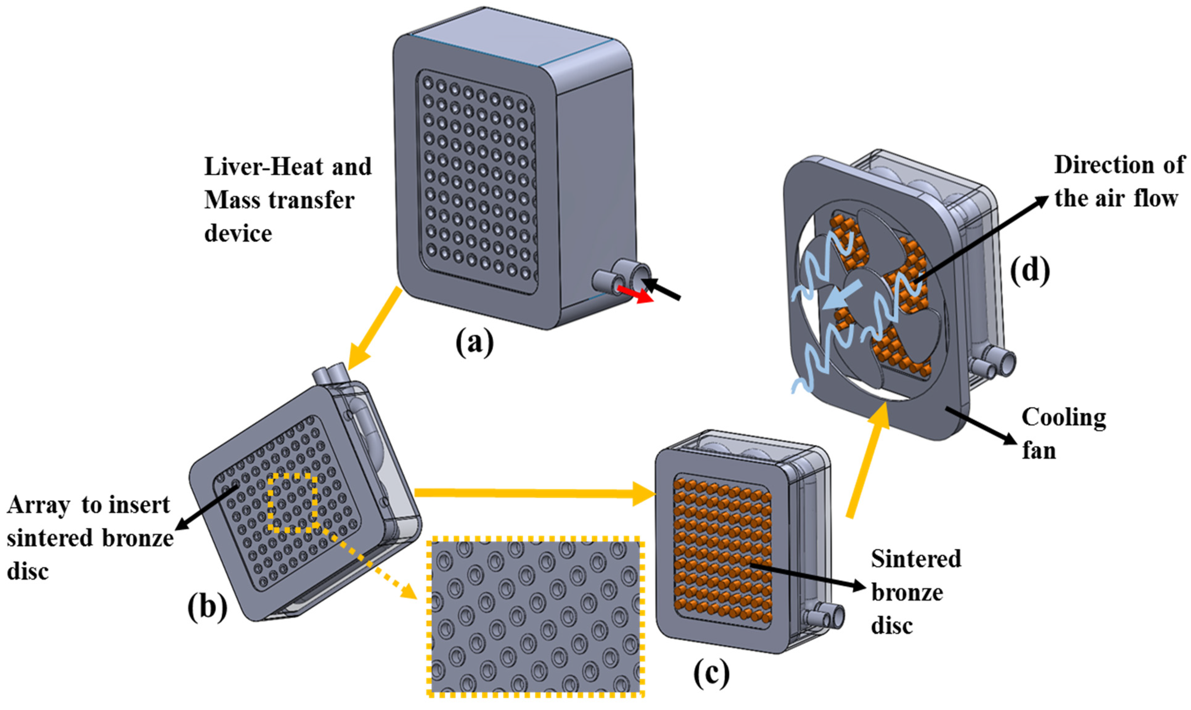
2. Biomimicry Design and Manufacturing
3. Materials, Methods, and Manufacturing
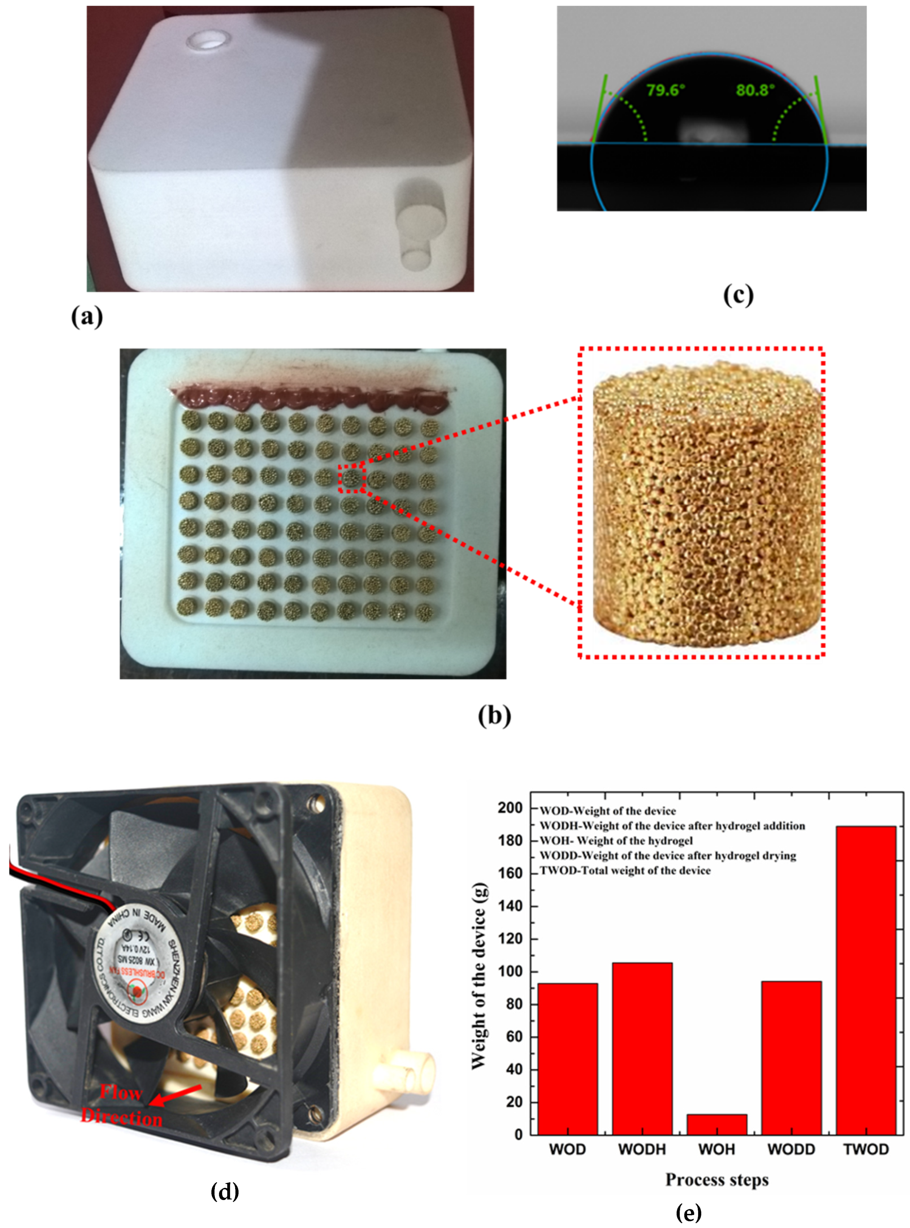
3.1. LHMT Device Fabrication
3.2. Hydrogel Synthesis and Integration
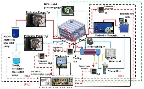
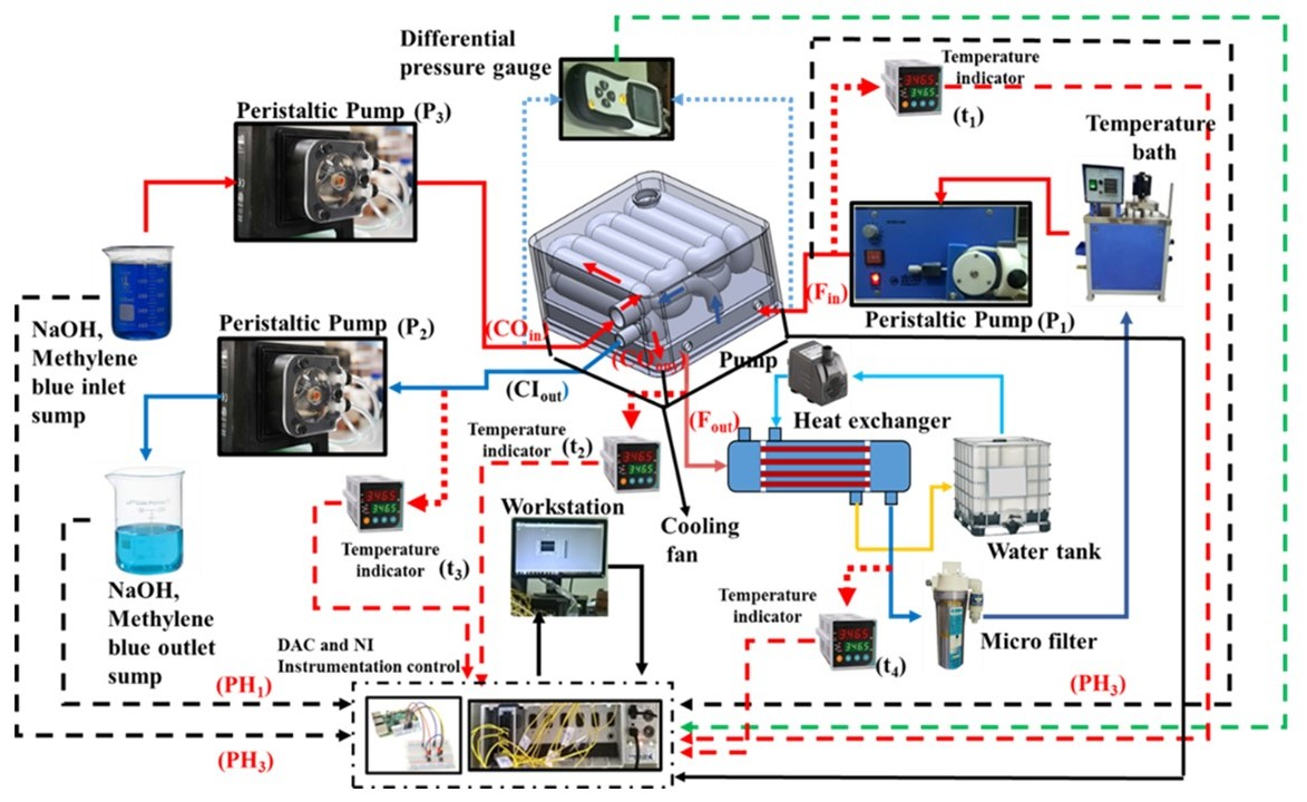
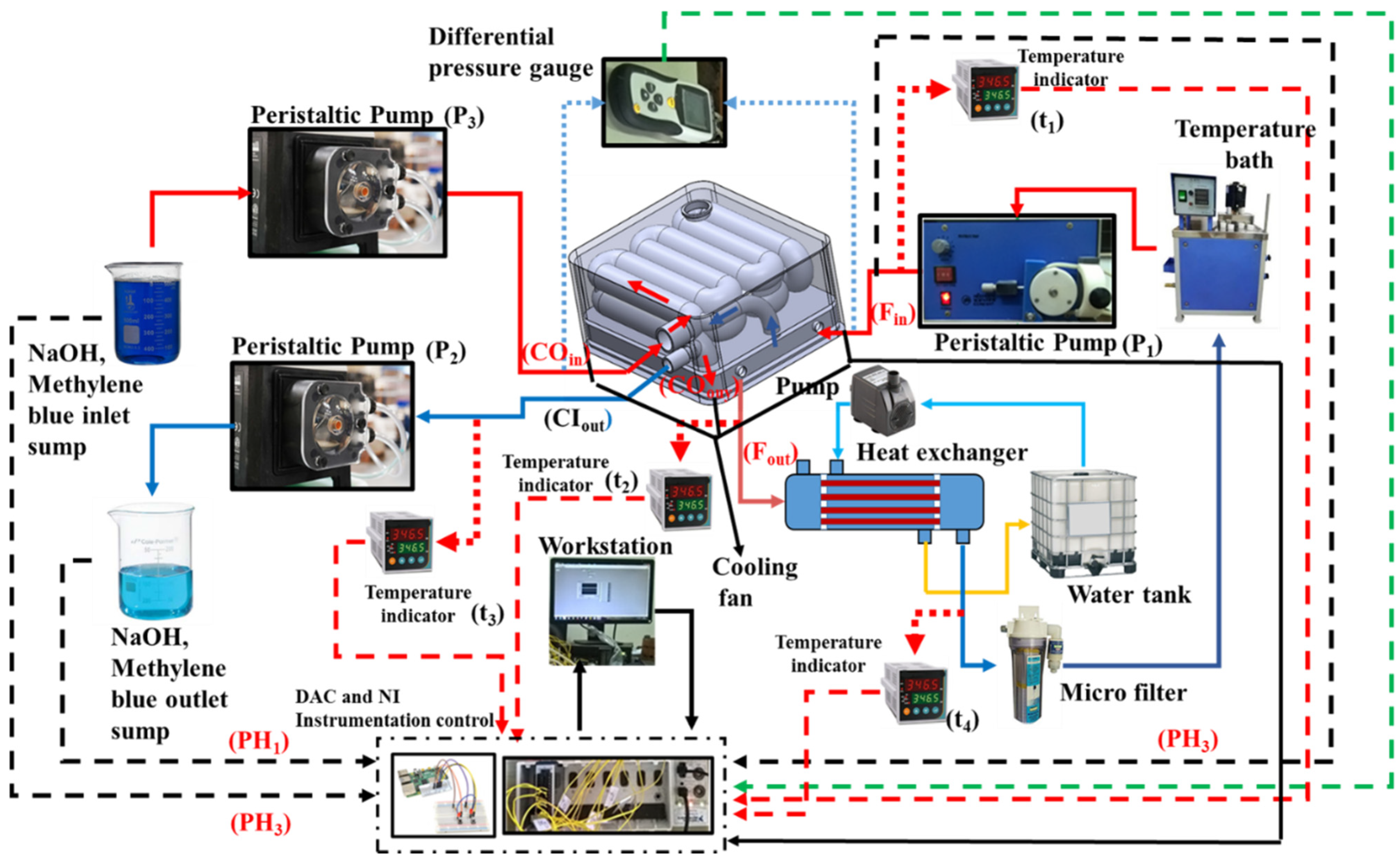
3.3. Experimental Flow Line
4. Results and Discussion
Temperature-Dependent Hydrogel Study
5. Summary and Conclusions
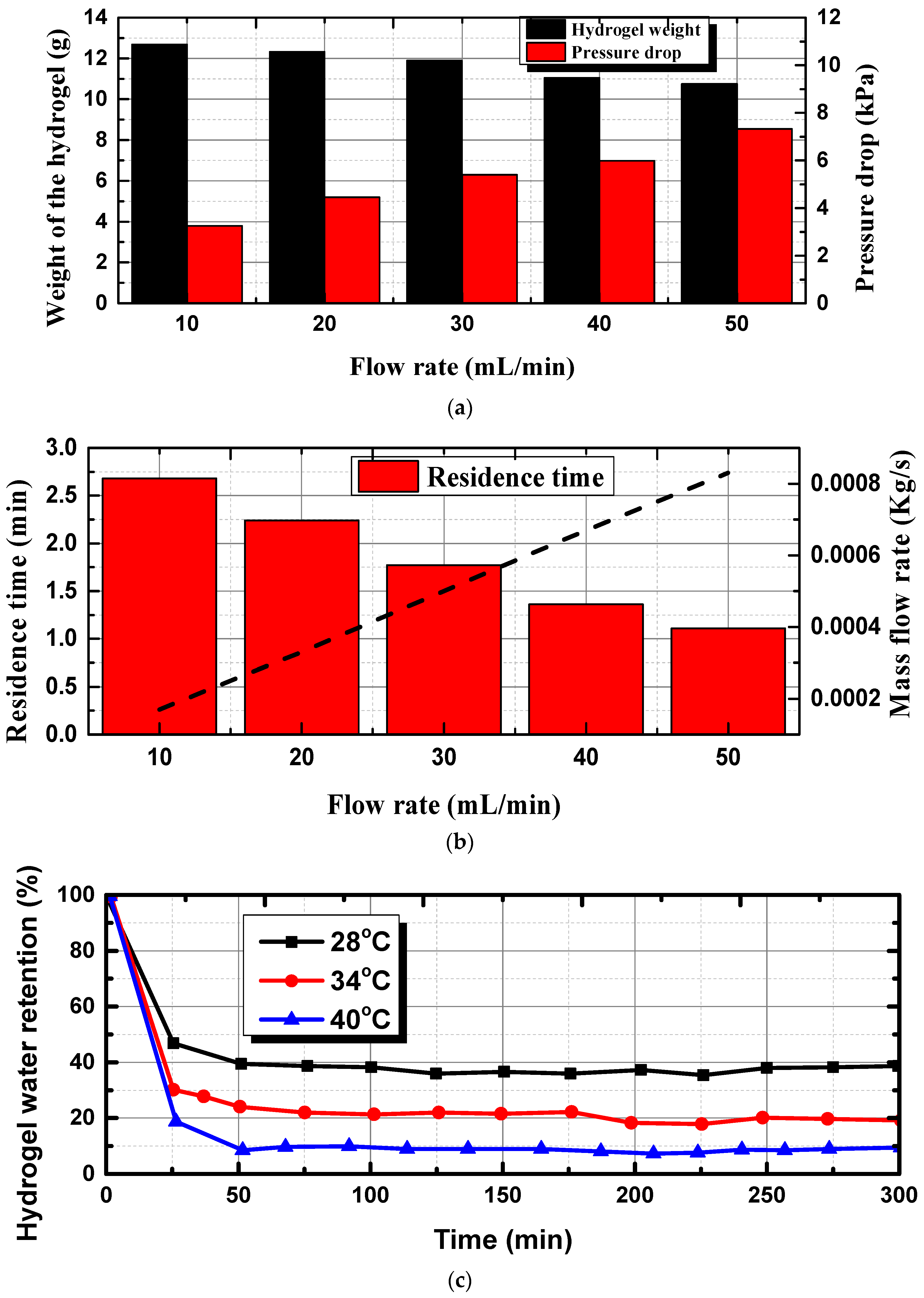
- The weight of the hydrogel was maximum at 10 mL/min and decreased by 25.29% to 10.12 g for the flow rate of 50 mL/min. On the other hand, the increase in flow rate to 50 mL/min delivered the maximum pressure drop of 7.21 kPa.
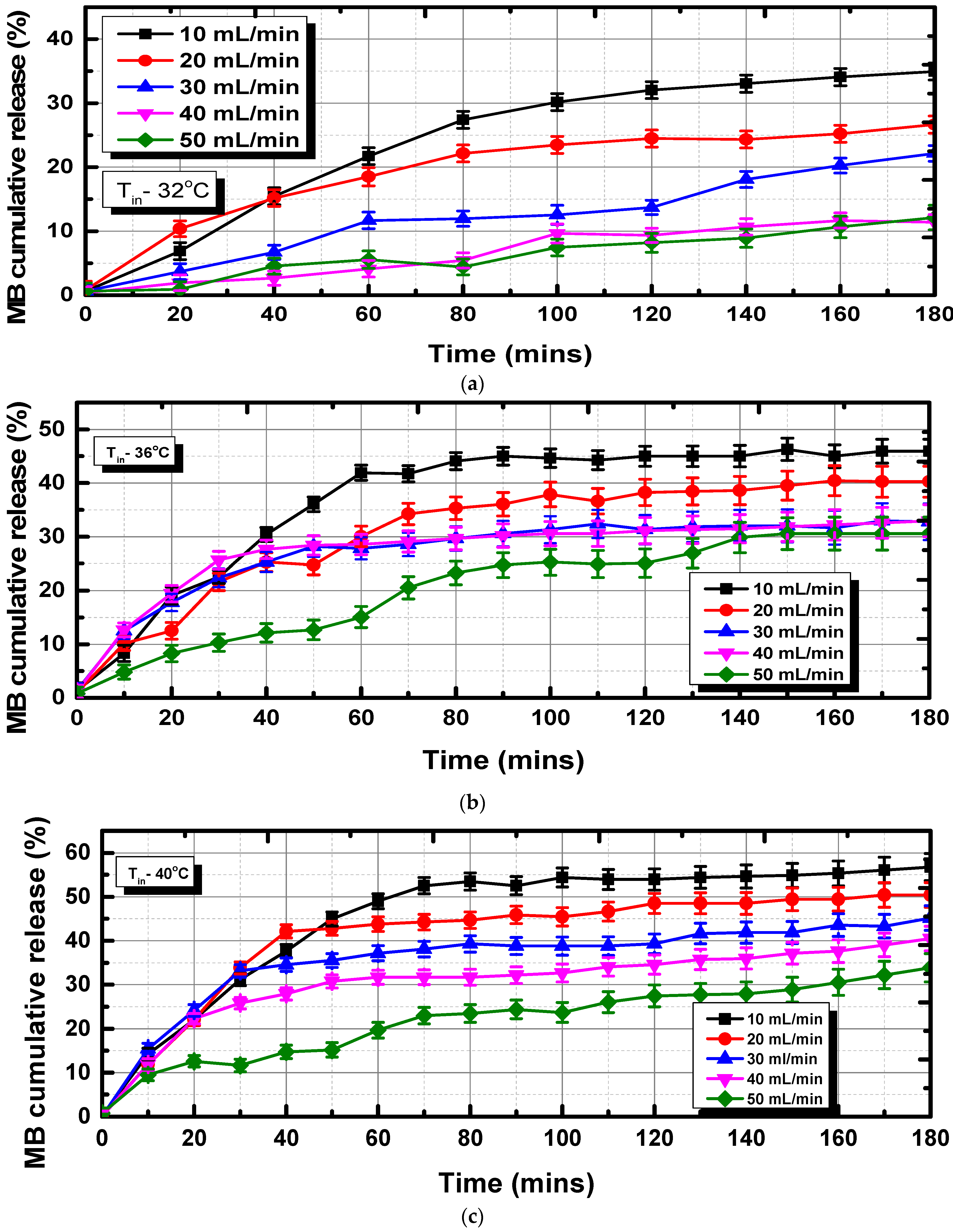
- The cumulative MB release at 30 °C increased to 47% at the lower flow rate of 10 mL/min, and the cumulative release at 40 °C climbed to 55%, which is 44.7% more than at 30 °C.
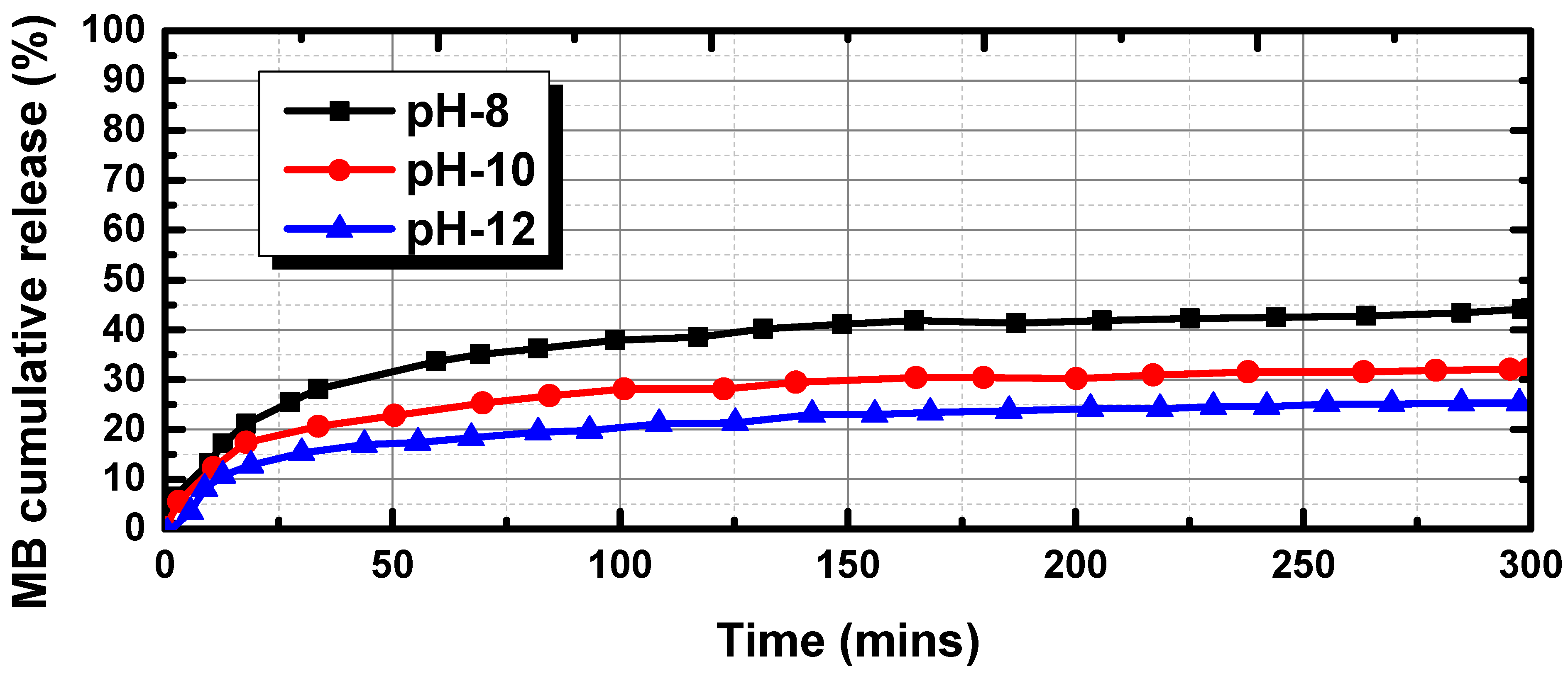
- The MB release rates considerably increased when the pH dropped from 12 to 8, showing that the lower pH had a major impact on the release of MD from the hydrogel. Only 19% of the MB was released at pH 12 after 50 min, and, after that, the release rate remained nearly constant until about 26% of the MB was released, after 300 min.
- The results show that hydrogels tested at higher fluid temperatures (40 °C) were quicker to de-swell and lost more water over time when compared to hydrogels tested at lower fluid temperatures (28 °C). At higher fluid temperatures, hydrogels lost approximately 80% of their water in just 20 min, compared to 50% at room temperature.
- From critical observations, it can be found that the impact of the weight gain of the hydrogel, due to swelling at an increased flow rate, is less than that of the increased pressure drop. At a lower flow rate, the hydrogel’s swelling over time is reflected in the increase in the weight of the hydrogel. We observed this behavior due to the pre-constructed walls that alter the swelling characteristics, due to which the hydrogel ultimately did not reach its final volume.
Author Contributions
Funding
Institutional Review Board Statement
Informed Consent Statement
Data Availability Statement
Acknowledgments
Conflicts of Interest
References
- Pless, G. Artificial and Bioartificial Liver Support. Organogenesis 2007, 3, 20–24. [Google Scholar] [CrossRef] [Green Version]
- Hernaez, R.; Solà, E.; Moreau, R.; Ginès, P. Acute-on-Chronic Liver Failure: An Update. Gut 2017, 66, 541–553. [Google Scholar] [CrossRef] [Green Version]
- Ganzert, M.; Felgenhauer, N.; Zilker, T. Indication of Liver Transplantation Following Amatoxin Intoxication. J. Hepatol. 2005, 42, 202–209. [Google Scholar] [CrossRef]
- Mansour, D.; McPherson, S. Management of Decompensated Cirrhosis. Clin. Med. J. R. Coll. Physicians Lond. 2018, 18, s60–s65. [Google Scholar] [CrossRef]
- Rai, R. Liver Transplantatation- an Overview. Indian J. Surg. 2013, 75, 185–191. [Google Scholar] [CrossRef] [Green Version]
- Hrusovský, S.; Danninger, F.; Kupcová, V.; Becker, M.C.; Mantion, G.; Miguet, J.P. Indications and Contraindications for Liver Transplantation. Bratisl. Lek. Listy 1996, 97, 12–18. [Google Scholar] [CrossRef]
- Tandon, R.; Froghi, S. Artificial Liver Support Systems. J. Gastroenterol. Hepatol. 2021, 36, 1164–1179. [Google Scholar] [CrossRef]
- Aldridge, D.R.; Tranah, E.J.; Shawcross, D.L. Pathogenesis of Hepatic Encephalopathy: Role of Ammonia and Systemic Inflammation. J. Clin. Exp. Hepatol. 2015, 5, S7–S20. [Google Scholar] [CrossRef] [Green Version]
- Davenport, A. Portable and Wearable Dialysis Devices for the Treatment of Patients with End-Stage Kidney Failure: Wishful Thinking or Just over the Horizon? Pediatr. Nephrol. 2015, 30, 2053–2060. [Google Scholar] [CrossRef] [Green Version]
- Narendran, G.; Hoque, S.Z.; Satpathi, N.S.; Nampoothiri, K.N.; Sen, A.K. PDMS Membrane-Based Flexible Bi-Layer Microfluidic Device for Blood Oxygenation. J. Micromech. Microeng. 2022, 32, 094001. [Google Scholar] [CrossRef]
- Nam, D.; Chapiro, J.; Paradis, V.; Seraphin, T.P.; Kather, J.N. Artificial Intelligence in Liver Diseases: Improving Diagnostics, Prognostics and Response Prediction. JHEP Rep. 2022, 4, 100443. [Google Scholar] [CrossRef]
- Kilmer, P.D. Review Article: Review Article. Journalism 2010, 11, 369–373. [Google Scholar] [CrossRef]
- De Pont, A.C.J.M. Extracorporeal Treatment of Intoxications. Curr. Opin. Crit. Care 2007, 13, 668–673. [Google Scholar] [CrossRef] [PubMed]
- Yamamoto, S.; Kazama, J.J.; Wakamatsu, T.; Takahashi, Y.; Kaneko, Y.; Goto, S.; Narita, I. Removal of Uremic Toxins by Renal Replacement Therapies: A Review of Current Progress and Future Perspectives. Ren. Replace. Ther. 2016, 2, 43. [Google Scholar] [CrossRef] [Green Version]
- King, J.D.; Kern, M.H.; Jaar, B.G. Extracorporeal Removal of Poisons and Toxins. Clin. J. Am. Soc. Nephrol. 2019, 14, 1408–1415. [Google Scholar] [CrossRef] [PubMed]
- Shalkham, A.S.; Kirrane, B.M.; Hoffman, R.S.; Goldfarb, D.S.; Nelson, L.S. The Availability and Use of Charcoal Hemoperfusion in the Treatment of Poisoned Patients. Am. J. Kidney Dis. 2006, 48, 239–241. [Google Scholar] [CrossRef] [PubMed]
- Dou, W.; Wang, J.; Yao, Z.; Xiao, W.; Huang, M.; Zhang, L. A Critical Review of Hemoperfusion Adsorbents: Materials, Functionalization and Matrix Structure Selection. Mater. Adv. 2022, 3, 918–930. [Google Scholar] [CrossRef]
- Hirano, R.; Namazuda, K.; Hirata, N. Double Filtration Plasmapheresis: Review of Current Clinical Applications. Ther. Apher. Dial. 2021, 25, 145–151. [Google Scholar] [CrossRef]
- Tao, X.; Thijssen, S.; Kotanko, P.; Ho, C.H.; Henrie, M.; Stroup, E.; Handelman, G. Improved Dialytic Removal of Protein-Bound Uraemic Toxins with Use of Albumin Binding Competitors: An in Vitro Human Whole Blood Study. Sci. Rep. 2016, 6, 2–10. [Google Scholar] [CrossRef] [Green Version]
- Sparrelid, E.; Gilg, S.; van Gulik, T.M. Systematic Review of MARS Treatment in Post-Hepatectomy Liver Failure. HPB 2020, 22, 950–960. [Google Scholar] [CrossRef]
- Steiner, C.; Mitzner, S. Experiences with MARS Liver Support Therapy in Liver Failure: Analysis of 176 Patients of the International MARS Registry. Liver 2002, 22, 20–25. [Google Scholar] [CrossRef]
- Krenzien, F.; Katou, S.; Papa, A.; Sinn, B.; Benzing, C.; Feldbrügge, L.; Kamali, C.; Brunnbauer, P.; Splith, K.; Lorenz, R.R.; et al. Increased Cell-Free DNA Plasma Concentration Following Liver Transplantation Is Linked to Portal Hepatitis and Inferior Survival. J. Clin. Med. 2020, 9, 1543. [Google Scholar] [CrossRef]
- Niewinski, G.; Raszeja-Wyszomirska, J.; Hrenczuk, M.; Rozga, A.; Malkowski, P.; Rozga, J. Intermittent High-Flux Albumin Dialysis with Continuous Venovenous Hemodialysis for Acute-on-Chronic Liver Failure and Acute Kidney Injury. Artif. Organs 2020, 44, 91–99. [Google Scholar] [CrossRef] [PubMed] [Green Version]
- Sponholz, C.; Matthes, K.; Rupp, D.; Backaus, W.; Klammt, S.; Karailieva, D.; Bauschke, A.; Settmacher, U.; Kohl, M.; Clemens, M.G.; et al. Molecular Adsorbent Recirculating System and Single-Pass Albumin Dialysis in Liver Failure—A Prospective, Randomised Crossover Study. Crit. Care 2016, 20, 2. [Google Scholar] [CrossRef] [PubMed] [Green Version]
- Sauer, I.M.; Goetz, M.; Steffen, I.; Walter, G.; Kehr, D.C.; Schwartlander, R.; Hwang, Y.J.; Pascher, A.; Gerlach, J.C.; Neuhaus, P. In Vitro Comparison of the Molecular Adsorbent Recirculation System (MARS) and Single-Pass Albumin Dialysis (SPAD). Hepatology 2004, 39, 1408–1414. [Google Scholar] [CrossRef] [PubMed]
- García Martínez, J.J.; Bendjelid, K. Artificial Liver Support Systems: What Is New over the Last Decade? Ann. Intensive Care 2018, 8, 109. [Google Scholar] [CrossRef] [Green Version]
- Palem, R.R.; Rao, K.M.; Shimoga, G.; Saratale, R.G.; Shinde, S.K.; Ghodake, G.S.; Lee, S.H. Physicochemical Characterization, Drug Release, and Biocompatibility Evaluation of Carboxymethyl Cellulose-Based Hydrogels Reinforced with Sepiolite Nanoclay. Int. J. Biol. Macromol. 2021, 178, 464–476. [Google Scholar] [CrossRef] [PubMed]
- Reddy, P.R.S.; Rao, K.M.; Rao, K.S.V.K.; Shchipunov, Y.; Ha, C.S. Synthesis of Alginate Based Silver Nanocomposite Hydrogels for Biomedical Applications. Macromol. Res. 2014, 22, 832–842. [Google Scholar] [CrossRef]
- Palem, R.R.; Saha, N.; Shimoga, G.D.; Kronekova, Z.; Sláviková, M.; Saha, P. Chitosan–Silver Nanocomposites: New Functional Biomaterial for Health-Care Applications. Int. J. Polym. Mater. Polym. Biomater. 2018, 67, 1–10. [Google Scholar] [CrossRef] [Green Version]
- Palem, R.R.; Shimoga, G.; Kang, T.J.; Lee, S.H. Fabrication of Multifunctional Guar Gum-Silver Nanocomposite Hydrogels for Biomedical and Environmental Applications. Int. J. Biol. Macromol. 2020, 159, 474–486. [Google Scholar] [CrossRef]
- Rama Subba Reddy, P.; Krishna Rao, K.S.V.; Madhusudana Rao, K.; Sivagangi Reddy, N.; Eswaramma, S. PH Sensitive Poly(Methyl Methacrylate-Co-Acryloyl Phenylalanine) Nanogels and Their Silver Nanocomposites for Biomedical Applications. J. Drug Deliv. Sci. Technol. 2015, 29, 181–188. [Google Scholar] [CrossRef]
- Ahmed, E.M. Hydrogel: Preparation, Characterization, and Applications: A Review. J. Adv. Res. 2015, 6, 105–121. [Google Scholar] [CrossRef] [Green Version]
- Ye, S.; Boeter, J.W.B.; Penning, L.C.; Spee, B.; Schneeberger, K. Hydrogels for Liver Tissue Engineering. Bioengineering 2019, 6, 59. [Google Scholar] [CrossRef] [PubMed] [Green Version]
- Chang, S.H.; Custer, P.L.; Mohadjer, Y.; Scott, E. Use of Lorenz Titanium Implants in Orbital Fracture Repair. Ophthal. Plast. Reconstr. Surg. 2009, 25, 119–122. [Google Scholar] [CrossRef] [PubMed]
- Hoare, T.R.; Kohane, D.S. Hydrogels in Drug Delivery: Progress and Challenges. Polymer 2008, 49, 1993–2007. [Google Scholar] [CrossRef] [Green Version]
- Eivazzadeh-Keihan, R.; Sadat, Z.; Aghamirza Moghim Aliabadi, H.; Ganjali, F.; Kashtiaray, A.; Salimi Bani, M.; Komijani, S.; Ahadian, M.M.; salehpour, N.; Ahangari Cohan, R.; et al. Fabrication of a Magnetic Alginate-Silk Fibroin Hydrogel, Containing Halloysite Nanotubes as a Novel Nanocomposite for Biological and Hyperthermia Applications. Sci. Rep. 2022, 12, 15431. [Google Scholar] [CrossRef] [PubMed]
- Liu, H.; Prachyathipsakul, T.; Koyasseril-Yehiya, T.M.; Le, S.P.; Thayumanavan, S. Molecular Bases for Temperature Sensitivity in Supramolecular Assemblies and Their Applications as Thermoresponsive Soft Materials. Mater. Horiz. 2022, 9, 164–193. [Google Scholar] [CrossRef]
- Pardeshi, S.; Damiri, F.; Zehravi, M.; Joshi, R.; Kapare, H.; Prajapati, M.K.; Munot, N.; Berrada, M.; Giram, P.S.; Rojekar, S.; et al. Functional Thermoresponsive Hydrogel Molecule to Material Design for Biomedical Applications. Polymers 2022, 14, 3126. [Google Scholar] [CrossRef]
- Dai, H.; Chen, Q.; Qin, H.; Guan, Y.; Shen, D.; Hua, Y.; Tang, Y.; Xu, J. A Temperature-Responsive Copolymer Hydrogel in Controlled Drug Delivery. Macromolecules 2006, 39, 6584–6589. [Google Scholar] [CrossRef]
- Chen, J.; Liu, M.; Liu, H.; Ma, L.; Gao, C.; Zhu, S.; Zhang, S. Synthesis and Properties of Thermo- and PH-Sensitive Poly(Diallyldimethylammonium Chloride)/Poly(N,N-Diethylacrylamide) Semi-IPN Hydrogel. Chem. Eng. J. 2010, 159, 247–256. [Google Scholar] [CrossRef]
- Ramanan, R.M.K.; Chellamuthu, P.; Tang, L.; Nguyen, K.T. Development of a Temperature-Sensitive Composite Hydrogel for Drug Delivery Applications. Biotechnol. Prog. 2006, 22, 118–125. [Google Scholar] [CrossRef] [PubMed]
- Sun, G.; Zhang, X.Z.; Chu, C.C. Formulation and Characterization of Chitosan-Based Hydrogel Films Having Both Temperature and PH Sensitivity. J. Mater. Sci. Mater. Med. 2007, 18, 1563–1577. [Google Scholar] [CrossRef] [PubMed]
- Alvarez-Lorenzo, C.; Concheiro, A. Reversible Adsorption by a PH- and Temperature-Sensitive Acrylic Hydrogel. J. Control. Release 2002, 80, 247–257. [Google Scholar] [CrossRef]
- Qiao, P.; Niu, Q.; Wang, Z.; Cao, D. Synthesis of Thermosensitive Micelles Based on Poly(N-Isopropylacrylamide) and Poly(l-Alanine) for Controlled Release of Adriamycin. Chem. Eng. J. 2010, 159, 257–263. [Google Scholar] [CrossRef]
- Ji, H.; Song, X.; Cheng, H.; Luo, L.; Huang, J.; He, C.; Yin, J.; Zhao, W.; Qiu, L.; Zhao, C. Biocompatible in Situ Polymerization of Multipurpose Polyacrylamide-Based Hydrogels on Skin via Silver Ion Catalyzation. ACS Appl. Mater. Interfaces 2020, 12, 31079–31089. [Google Scholar] [CrossRef]
- Saygili, E.; Kaya, E.; Ilhan-Ayisigi, E.; Saglam-Metiner, P.; Alarcin, E.; Kazan, A.; Girgic, E.; Kim, Y.W.; Gunes, K.; Eren-Ozcan, G.G.; et al. An Alginate-Poly(Acrylamide) Hydrogel with TGF-Β3 Loaded Nanoparticles for Cartilage Repair: Biodegradability, Biocompatibility and Protein Adsorption. Int. J. Biol. Macromol. 2021, 172, 381–393. [Google Scholar] [CrossRef]
- Zarrin, N.K.; Mottaghitalab, F.; Reis, R.L.; Kundu, S.C.; Farokhi, M. Thermosensitive Chitosan/Poly(N-Isopropyl Acrylamide) Nanoparticles Embedded in Aniline Pentamer/Silk Fibroin/Polyacrylamide as an Electroactive Injectable Hydrogel for Healing Critical-Sized Calvarial Bone Defect in Aging Rat Model. Int. J. Biol. Macromol. 2022, 213, 352–368. [Google Scholar] [CrossRef]
- Akkaya, B.; Akkaya, R.; Celikkaya, S.I.; Sarıaydin, N.; Raheem, K.Y. Doxorubucin Loaded PH-Responsive Chitosan-Poly(Acrylamide-Maleic Acid) Composite Hydrogel for Anticancer Targeting. J. Mol. Struct. 2023, 1274, 134536. [Google Scholar] [CrossRef]
- Lv, J.; Fang, Y.; Wu, M.; Ou, X.; Zhang, W.; Wang, S.; Li, H.; Shang, L.; He, M.; Zhao, Y. Poly(Acrylamide) Hydrogel Composites with Microsized β-Chitin Fiber and the Properties of Mechanical and Drug Release. Mater. Today Commun. 2023, 34, 105163. [Google Scholar] [CrossRef]
- Narendran, G.; Mallikarjuna, B.; Nagesha, B.K.; Gnanasekaran, N. Experimental Investigation on Additive Manufactured Single and Curved Double Layered Microchannel Heat Sink with Nanofluids. Heat Mass Transf. Waerme Stoffuebertragung 2023. [Google Scholar] [CrossRef]
- Francis, K.; (Royal College of Surgeons, London, UK). The Anatomy and Physiology of the Liver. Personal communication, 1833.
- Bouchier, I.A.D. Book Review The Liver: Morphology, Biochemistry, Physiology. N. Engl. J. Med. 1964, 271, 1170. [Google Scholar] [CrossRef]
- Mitra, V.; Metcalf, J. Functional Anatomy and Blood Supply of the Liver. Anaesth. Intensive Care Med. 2009, 10, 332–333. [Google Scholar] [CrossRef]
- Lee, I.C.; Huo, T.I.; Huang, Y.H. Gastrointestinal and Liver Manifestations in Patients with COVID-19. J. Chin. Med. Assoc. 2020, 83, 521–523. [Google Scholar] [CrossRef] [PubMed]
- Louf, J.F.; Lu, N.B.; O’Connell, M.G.; Cho, H.J.; Datta, S.S. Under Pressure: Hydrogel Swelling in a Granular Medium. Sci. Adv. 2021, 7, eabd2711. [Google Scholar] [CrossRef] [PubMed]


| Author | Hydrogel | Compatibility/Application |
|---|---|---|
| Ji et al. [45] | Polyacrylamide by silver ion catalyzation | Biocompatible/tissue adhesion and Wound dressing |
| Saygili et al. [46] | Alginate-poly(acrylamide) hydrogel with TGF-β3 loaded nanoparticles | Biodegradability, biocompatible, and protein adsorption/cartilage repair |
| Zarrin et al. [47] | Polyacrylamide | Biodegradability/calvarial bone defect healing |
| Akkaya et al. [48] | Chitosan-poly(acrylamide-maleic acid) | Biocompatible/anticancer (MCF-7) drug doxorubicin targeted |
| Lv et al. [49] | Poly(acrylamide) with microsized β-chitin fiber | Biocompatible/arthritis treatment |
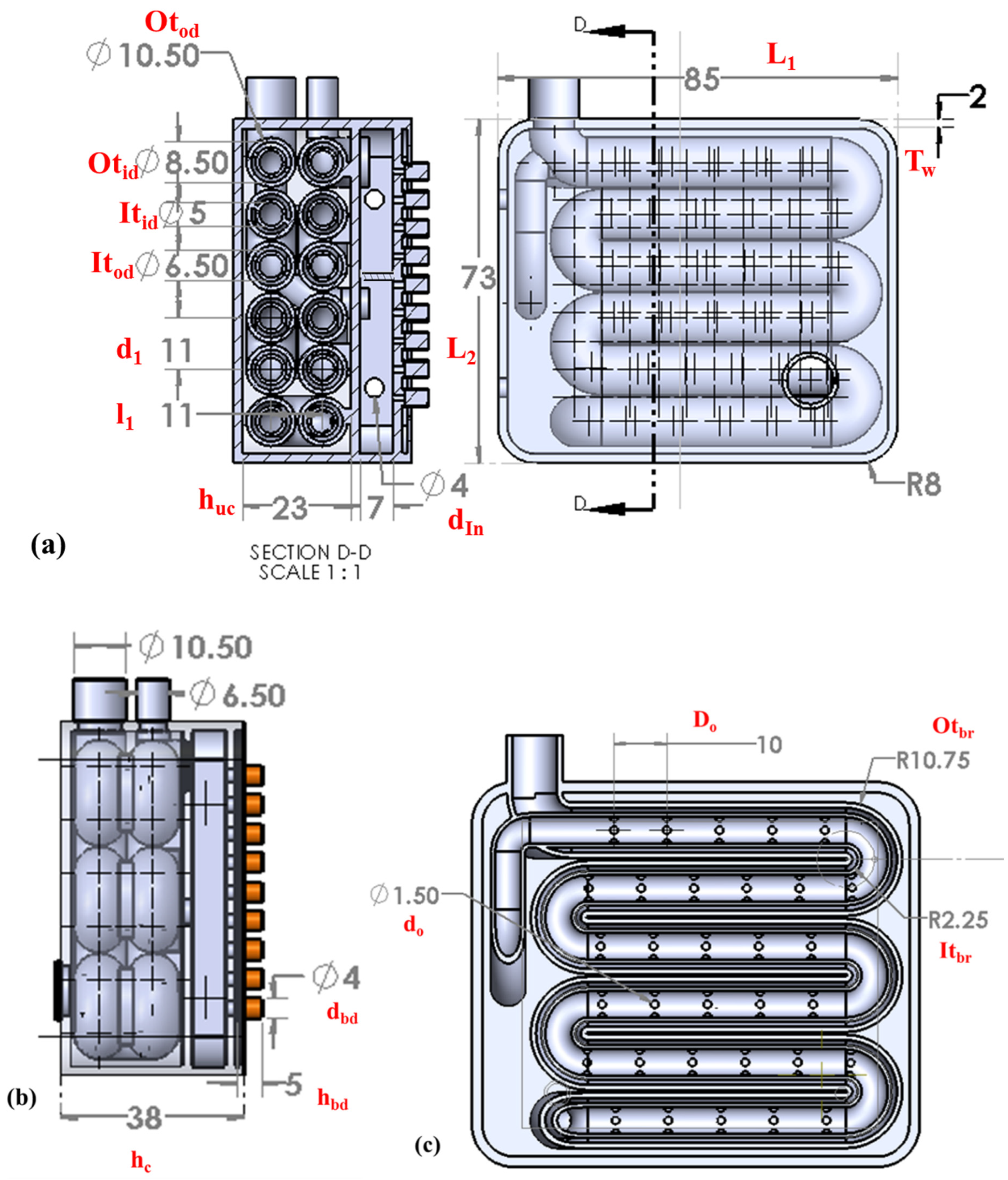
| S. No | Design Parameters | Dimensions (mm) |
|---|---|---|
| 1 | Length of the chamber (L1) | 85 |
| 2 | Breadth of the chamber (L2) | 73 |
| 3 | Chamber wall thickness (Tw) | 2 |
| 4 | Outer diameter of the outer tube (Otod) | 10.50 |
| 5 | Outer diameter of inner tube (Otid) | 8.50 |
| 6 | Inner tube outer diameter (Itod) | 6.50 |
| 7 | Inner tube inner diameter (Itid) | 5 |
| 8 | Centerline distance between two tubes (d1) | 11 |
| 9 | Centerline distance between the first and second layer of two tubes (l1) | 11 |
| 10 | Height of the upper chamber (huc) | 23 |
| 11 | Height of the lower chamber (hlc) | 7 |
| 12 | Diameter of the hot water fluid inlet (din) | 4 |
| 13 | Total height of the chamber (hc) | 38 |
| 14 | Diameter of the bronze disc (dbd) | 4 |
| 15 | Diameter of the bronze disc (hbd) | 5 |
| 16 | Diameter of the orifice (do) | 1.50 |
| 17 | Distance between two orifices (Do) | 10 |
| 18 | Outer tube bend radius (Otbr) | 10.75 |
| 19 | Inner tube bend radius (Itbr) | 2.25 |
Disclaimer/Publisher’s Note: The statements, opinions and data contained in all publications are solely those of the individual author(s) and contributor(s) and not of MDPI and/or the editor(s). MDPI and/or the editor(s) disclaim responsibility for any injury to people or property resulting from any ideas, methods, instructions or products referred to in the content. |
© 2023 by the authors. Licensee MDPI, Basel, Switzerland. This article is an open access article distributed under the terms and conditions of the Creative Commons Attribution (CC BY) license (https://creativecommons.org/licenses/by/4.0/).
Share and Cite
Narendran, G.; Walunj, A.; Kumar, A.M.; Jeyachandran, P.; Awwad, N.S.; Ibrahium, H.A.; Gorji, M.R.; Perumal, D.A. Experimental Demonstration of Compact Polymer Mass Transfer Device Manufactured by Additive Manufacturing with Hydrogel Integration to Bio-Mimic the Liver Functions. Bioengineering 2023, 10, 416. https://doi.org/10.3390/bioengineering10040416
Narendran G, Walunj A, Kumar AM, Jeyachandran P, Awwad NS, Ibrahium HA, Gorji MR, Perumal DA. Experimental Demonstration of Compact Polymer Mass Transfer Device Manufactured by Additive Manufacturing with Hydrogel Integration to Bio-Mimic the Liver Functions. Bioengineering. 2023; 10(4):416. https://doi.org/10.3390/bioengineering10040416
Chicago/Turabian StyleNarendran, Ganesan, Avdhoot Walunj, A. Mohan Kumar, Praveen Jeyachandran, Nasser S. Awwad, Hala A. Ibrahium, M. R. Gorji, and D. Arumuga Perumal. 2023. "Experimental Demonstration of Compact Polymer Mass Transfer Device Manufactured by Additive Manufacturing with Hydrogel Integration to Bio-Mimic the Liver Functions" Bioengineering 10, no. 4: 416. https://doi.org/10.3390/bioengineering10040416