Article

Study of the Cathode Pt-Electrocatalysts Based on Reduced Graphene Oxide with Pt-SnO2 Hetero-Clusters

by
Dmitry D. Spasov
1,2,*,
Nataliya A. Ivanova
1,
Ruslan M. Mensharapov
1,
Matvey V. Sinyakov
1,3,
Adelina A. Zasypkina
1,
Elena V. Kukueva
1,
Alexander L. Trigub
1,
Elizaveta S. Kulikova
1 and
Vladimir N. Fateev
1
1
National Research Center “Kurchatov Institute”, 1, Akademika Kurchatova Sq., 123182 Moscow, Russia
2
Department of Chemistry and Electrochemical Energy, National Research University “Moscow Power Engineering Institute”, 14, Krasnokazarmennaya St., 111250 Moscow, Russia
3
Institute of Modern Energetics and Nanotechnology, D. Mendeleev University of Chemical Technology of Russia, 9, Miusskaya Square, 125047 Moscow, Russia
*
Author to whom correspondence should be addressed.
Inorganics 2023, 11(8), 325; https://doi.org/10.3390/inorganics11080325
Submission received: 13 June 2023 / Revised: 17 July 2023 / Accepted: 28 July 2023 / Published: 31 July 2023
(This article belongs to the Special Issue 10th Anniversary of Inorganics: Inorganic Solid State Chemistry)

Abstract

:
A complex study of the structure, morphology, and electrochemical properties of the Pt20/SnO210/RGO electrocatalyst is presented. The advantage of the chemical synthesis of reduced graphene oxide (c-RGO) compared to thermal methods (t-RGO) is due to the formation of graphene plates with amorphous carbon black agglomerates and the chemical composition of the surface. The nature of the interaction between platinum and tin dioxide particles and a conclusion about the formation of heterostructures Pt-SnO2 with the surface interaction of lattices excluding the formation of hetero phases has been established. This achieves high dispersity during the formation of platinum particles without significant agglomeration and increases the electrochemical surface area (ESA) of platinum to 85 m2 g−1 vs. carbon black. In addition, the surface interaction of particles and the formation of hetero-clusters Pt-SnO2 can cause the improved activity and stability of the Pt20/SnO210/c-RGO electrocatalyst.

1. Introduction

Pt-based electrocatalysts are commonly used for proton-exchange membrane (PEM) fuel cells (FCs). Corrosion resistance is an important characteristic of suitable catalyst support, along with high electrical conductivity, high surface area, hydrophobicity, morphology, porosity, etc. This promising strategy aimed to mitigate carbon support limitations using carbon-based hybrid supports [1].
A complete rejection of Pt as an active component of PEMFC electrocatalysts seems premature, but a promising direction is the use of multicomponent complex systems, for example, platinum–tin dioxide (Pt-SnO2) clusters based on carbon support [2,3,4]. Tin oxide–carbon composites demonstrate high chemical and electrochemical stability, along with a strong interaction with supported metal nanoparticles [5]. The high durability of the Pt-SnO2-based catalysts is attributed to the strong metal–support interaction (SMSI) that inhibits the migration and agglomeration of the nanoparticles at the electrode surface. Previously, it was shown that the Pt20/SnO210/C electrocatalyst demonstrates increased stability during accelerated stress tests (AST) due to the high stability of SnO2 particles (10 wt.%) and their interaction with Pt [6,7]. However, the use of SnO2 lowers both the electrical conductivity of the electrocatalyst due to the semiconductor properties of SnO2 and the electrochemical surface area (ESA) due to the high degree of particle agglomeration.
An increase in the electrical conductivity and specific surface area of the catalyst can be achieved using complex carbon supports, which have a high specific surface area and increased electrical conductivity compared to amorphous carbon black. In this case, reduced graphene oxide (RGO) is a promising material for electrochemical power engineering due to its large specific surface area, high stability, and electrical conductivity [1]. RGO consists of plates of partially oxidized graphene, the basal planes of which are decorated with epoxy and hydroxyl groups, in addition to carbonyl and carboxyl groups located at the edges. RGO, in the physicochemical sense, is not equal to graphene; in other words, it is not possible to completely reduce graphite oxide (GO) to graphene. Thus, the products obtained during its reduction contain significant amounts of oxygen [8]. RGO is obtained in several stages, from graphite to GO to reduced graphene oxide. There are several methods for synthesizing GO, such as the Brodie method, the Staudenmaier method, and the Hummers method and its variants (the modified and improved Hummers method) [9,10].
RGO can be obtained directly by removing oxygen functional groups from GO according to various strategies: thermal reduction, photoreduction, electrochemical reduction, microwave reduction, solvothermal reduction, and chemical reduction using a wide range of reducing agents (hydroiodic acid, ascorbic acid, hydrazine, NaBH4 or hydrides of some metals) and multiphase recovery [11,12,13,14,15,16,17,18]. The resulting compounds can be used as supports for FC electrocatalysts. In [19,20,21,22], the electrochemical properties of the RGO catalyst were studied, showing a high ESA and stability in AST.
At present, complex multicomponent Pt (or Pd)/SnO2/RGO catalysts are being studied in various fields as gas-sensitive materials in gas sensors [23,24,25,26] and electrocatalysts for direct methanol fuel cells (DMFC) [27,28].
In [29], a hierarchically structured Pt/SnO2/RGO electrocatalyst was developed using layer-by-layer synthesis. A morphologically controlled synthesis was used to obtain regularly shaped SnO2 crystallites, including specific faces such as (101), (110), (111), and (221). Next, Pt nanoparticles were uniformly deposited on different faces of SnO2. The use of RGO made it possible to obtain an electrocatalyst with improved electronic conductivity and stability. The authors of [30] studied a series of Pt/SnO2/RGO electrocatalysts with a low Pt content (0.77, 0.89, and 1.21 wt.%). The photo-excited in situ loading of Pt clusters onto RGO-immobilized SnO2 was used in this work. The authors of [31] used the photo-assisted reduction method as an addition to traditional chemical reduction to obtain a well-hierarchical heterostructure of Pt@SnO2/graphene. The photo-assisted reduction method is an important method for regulating the interfacial interaction of active substances in hybrid electrocatalysts. As a result, the electrocatalyst exhibited significantly improved catalytic activity and increased cyclic stability. In studies [32], electrochemically exfoliated graphene (EEG) was used, which, according to the authors, was more suitable as catalyst support (EEG-Pt-eg, EEG-SnO2@Pt) than other carbon materials since it has a small amount of oxygen-containing functional groups and defects on the surface. All presented methods of synthesis were complex, and the resulting materials were used as gas-sensitive materials in gas sensors or in DMFC.
In the present work, a cathode electrocatalyst for PEMFC was studied. RGO was used as a support to increase the electrical conductivity and ESA of the electrocatalyst. In this case, the durability and inhibition of the processes of corrosion for the support, as well as the dissolution and coarsening of Pt particles, were ensured by the formation of metal–metal oxide hetero-clusters of Pt-SnO2. Both RGOs were preliminarily synthesized by thermal methods (t-RGO) and obtained by chemical reduction (c-RGO). The synthesis method saw a sequential reduction in component precursors to the final compound in a single content.

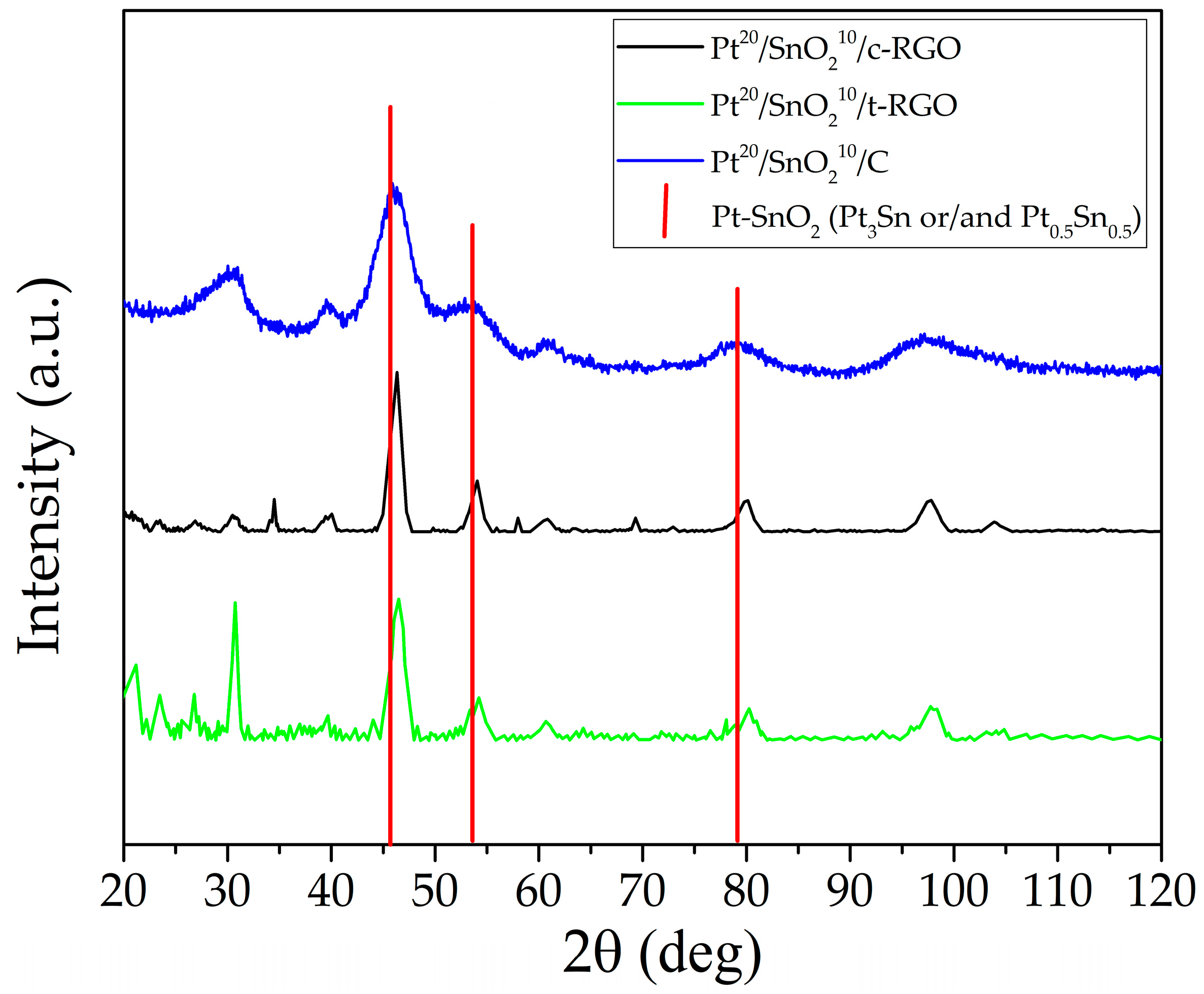
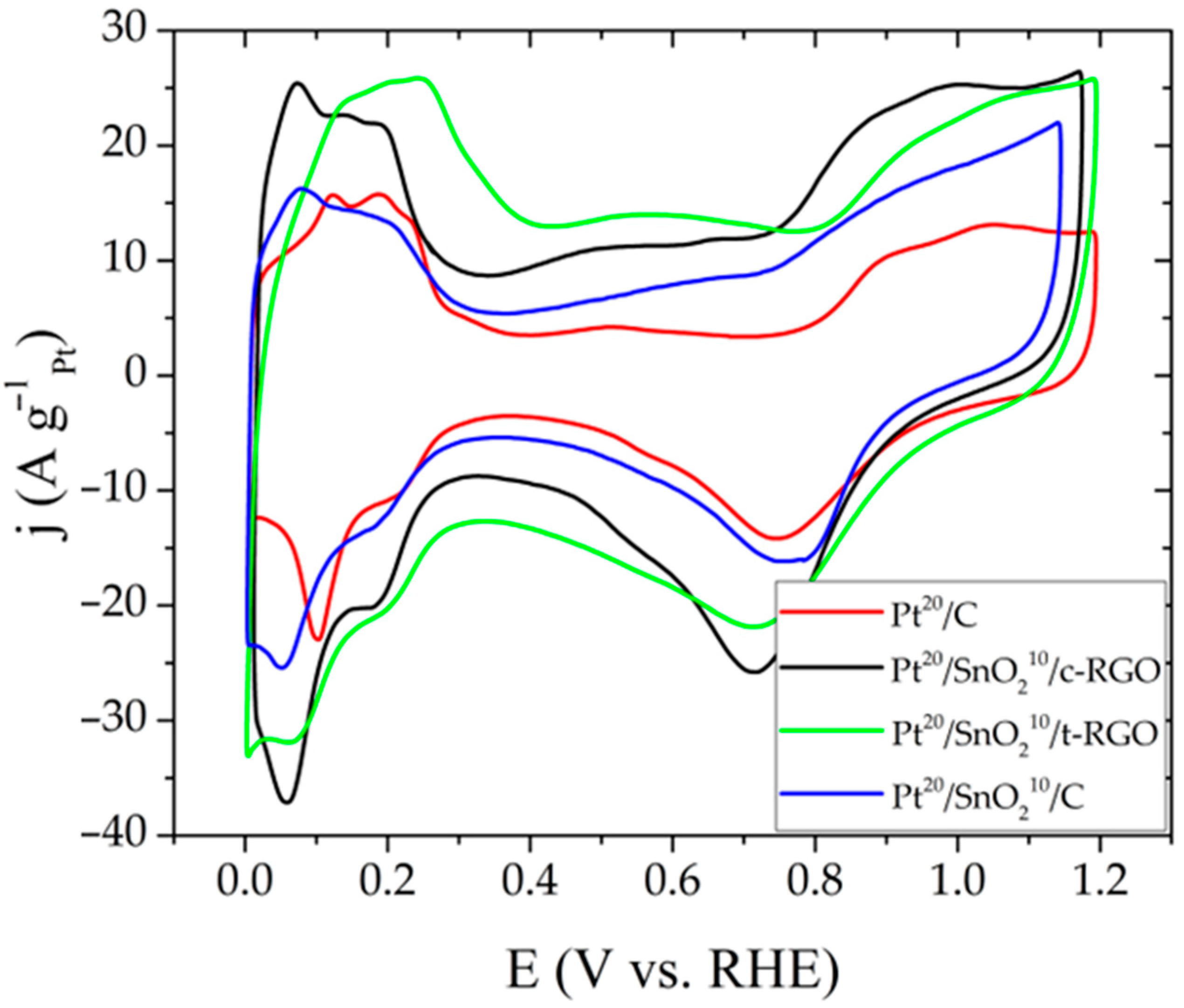
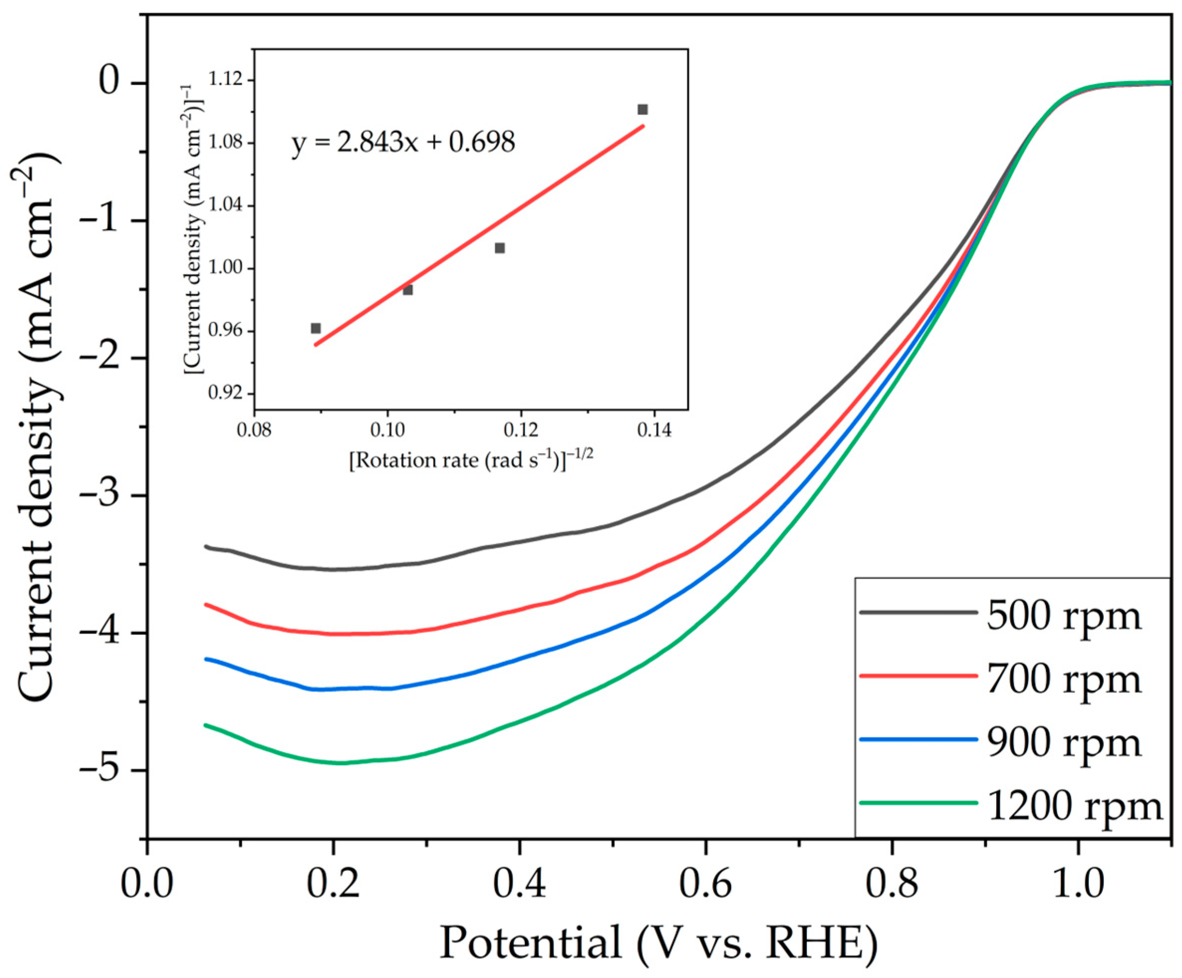
2. Results and Discussion

Figure 1 shows scanning electron microscopy (SEM) images (30 µm and 1 µm) of the studied electrocatalysts. On RGO samples obtained by thermal reduction (t-RGO), the layers of graphene sheets with a smooth, uniform surface were clearly pronounced. The sample obtained by chemical reduction (c-RGO) is characterized more by the presence of RGO sheets (nanosized thickness) with agglomerates of amorphous carbon black. The sizes of amorphous carbon black agglomerates deposited on graphene-type structures were about 100–300 nm.
Figure 2 shows the transmission electron microscopy (TEM) images of Pt20/SnO210/c-RGO and Pt20/SnO210/t-RGO electrocatalysts, particle size distribution, and fast Fourier transform (FFT) images.
According to the results of previous studies [6], it was shown that it is the SnO2 content of 10 wt.% that makes it possible to obtain a uniform distribution of particles without their significant agglomeration, which is also typical for samples based on RGO. Based on the analysis of the microphotograph (Figure 2), it was concluded that the particles were close to being spherical in shape and having a uniform distribution on the surface of the carbon support without large agglomerates. On high-resolution TEM images, a diffraction pattern can be distinguished in the form of parallel lines in image areas. Using FFT images, the interplanar spacing corresponding to Pt nanoparticles (0.22–0.23 nm) and SnO2 particles (0.26–0.27 nm) was determined, which made it possible to compose the particle size distribution (Figure 2). The interplanar distance corresponding to the Pt-SnO2 heterostructure (~0.2 nm) was also determined from the FFT image. The closeness of the lattice parameters did not allow us to isolate a specific interaction (Pt3Sn and/or Pt0.5Sn0.5) but indicated the formation of heterostructures.
For the studied electrocatalysts, a close particle size distribution of Pt and SnO2 was obtained. The average particle size of Pt was 2.1 nm (Pt20/SnO210/c-RGO) and 2.7 nm (Pt20/SnO210/t-RGO). For the electrocatalyst on c-RGO, a smaller size of platinum particles was observed, which could be associated with the synthesis of the electrocatalyst on reduced graphene oxide, as obtained by the chemical reduction method, and the presence of amorphous carbon black on the support surface. The average particle size of SnO2 was 3.7 nm (Pt20/SnO210/c-RGO) and 3.3 nm (Pt20/SnO210/t-RGO).
The actual content of Pt and Sn in all catalysts was confirmed by energy-dispersive X-ray spectroscopy (EDX) measurements (Table 1, Figure 3). In the case of t-RGO, the distribution of SnO2 was more scattered and could be associated with the composition of near-surface groups.
Table 1 presents the results of elemental analysis.
The obtained values of the content of Pt and SnO2 (the content of SnO2 was calculated based on the assumption that 100% of tin was in the form of dioxide) were close for both samples and correlated with the objective of synthesizing electrocatalysts.
Figure 4 shows the diffraction patterns of the investigated electrocatalysts.
The diffraction peaks around 31°, 39°, and 61° refer to the SnO2 planes. The diffraction peaks around 46°, 53°, 81°, and 96° are associated with the (111), (200), (220) and (331) Pt planes. The Pt20/SnO210/c-RGO and Pt20/SnO210/t-RGO samples were characterized by a peak at about 26°, which could be attributed to the RGO (002) graphite structure. The diffraction peak at 69.5° corresponds to the PtO phase and is present in all samples. PDF Cards are demonstrated in Figure S1.
According to the quantitative X-ray diffraction analysis for the Pt20/SnO210/c-RGO sample, the content of PtxSny phases was 10%, while in the Pt20/SnO210/t-RGO sample, it was only about 4%. The presence of PtxSny phases was indicated by the broadening of the peaks at about 46°, 53°, and 81°. The broadening of the peaks could also reflect an increase in the distance between platinum atoms in the lattice when the regularity of its structure was disturbed, including due to a surface interaction with heteroatoms. These effects were more pronounced for c-RGO.
XPS analysis was carried out in our previous work and was in good agreement with the literature data [6]. The SMSI effect in the prepared catalysts was induced by the formation of the Pt-SnO2 clusters in which the electron donation from the oxide to Pt metal was observed. This enhanced electron density on the Pt metal, providing the higher activity and stability of Pt nanoparticles. However, due to the low value of Pt 4f7/2, the binding energy shift was expected to be limited in its influence. Thus, the interaction between platinum and tin dioxide particles on the support surface was reflected by a low energy shift.
For samples of electrocatalysts, the curves of the Fourier transform modulus were obtained from the extended X-ray absorption fine structure (EXAFS) spectra (Figure 5), and the parameters of the atomic structure of Pt nanoparticles were estimated by fitting the model curve. Figure 5 shows the obtained experimental and model data.
The parameters obtained during the fitting of the theoretical curve are shown in Table 2.
The large value of the NPt-O number for the Pt20/C sample indicated the inclusion of oxygen atoms in the structure of Pt nanoparticles. Samples with RGO showed a lower number of NPt-O, which indicated a better reduction in Pt in these samples. Samples with SnO2 demonstrated a higher value of the coordination number of metallic Pt, which indicated a larger size of Pt nanoparticles due to agglomeration and competitive sorption with the modifier during synthesis. Wavelet transform of Pt L3-edge EXAFS for Pt foil, PtO2, Pt20/C, Pt20/SnO210/c-RGO, and Pt20/SnO210/t-RGO are demonstrated on Figure S2. The analysis of EXAFS spectra using the Wavelet transform did not allow us to distinguish the explicit contribution of Pt-Sn, which probably indicated only the surface contact of particles in the composition of Pt-SnO2 hetero-clusters.
To correlate these results, X-ray absorption near-edge structure (XANES) spectra were considered (Figure 6). As can be seen from the white line intensity, a larger amount of the oxide phase was present in the Pt20/C sample.
The white line peak of the XANES spectrum could also be represented as a linear combination of the Pt foil and PtO2 spectra. Table 3 shows the percentage contributions of the spectra of the reference samples to the spectra of the studied samples. The larger linear contribution of Pt foil to the spectrum for RGO-based samples could also indicate electron donation from the oxide (SnO2) to the Pt metal. This effect was reflected by Pt-catalysts based on the SnO2-C supports [33]. In the case of Pt3Sn/C electrocatalysts, an increase in the Pt 5d-orbital vacancy due to the redistribution of Pt 5d electrons to the low-energy 4d orbital of Sn could be observed [34].
The results of the performed analyses indicate the formation of Pt-SnO2 hetero-clusters mainly for the Pt20/SnO210/c-RGO sample, and the interaction of particles had more surface in nature and was based on the inclusion of tin atoms in the surface structure of Pt particles with the formation of a distorted crystal lattice corresponding to broadening platinum peaks in the diffraction pattern. Broadening picks could be mistakenly associated with corresponding PtxSny phases (Pt3Sn and/or Pt0.5Sn0.5).
Figure 7 shows the cyclic voltammograms (CVs) of the studied Pt20/SnO210/c-RGO, Pt20/SnO210/t-RGO, Pt20/C, and Pt20/SnO210/C [6] samples.
The deposition density, as well as the conditions for the synthesis of Pt and SnO2 particles, were identical for all samples; therefore, the difference between the current density of the double-layer region characterized diverse types of support. The larger current in the double-layer region reflected the high specific surface area of the RGO. As can be seen from the results of electrochemical studies, the use of RGO made it possible to significantly increase the ESA due to the larger specific surface area compared to a catalyst based on amorphous soot. The ESA of the Pt20/SnO210/c-RGO electrocatalyst was 1.5 times higher than that of the Pt20/SnO210/C [6] electrocatalyst (Table 4).
Figure 8 presents the results of the AST. For all catalysts, there was a gradual decrease in the ESA values associated with the agglomeration and separation of Pt particles, as well as the degradation of the carbon support. For the sample on t-RGO, the ESA loss was 92–94%. A sharp drop in ESA for t-RGO was associated with the destruction of the electrocatalyst due to the oxidation and corrosion of the support due to the presence of oxygen groups on the surface of the carbon structure. In turn, the precipitated SnO2 particles for t-RGO catalyzed the oxidation processes and accelerated the destruction in graphene under the action of high potentials, even when compared with Pt/RGO catalysts [35]. At the same time, the protective effect of applying SnO2 was not pronounced due to the absence of particle interactions.
The Pt20/SnO210/c-RGO and Pt20/SnO210/C [6] samples showed the highest stability in AST cycles. The loss was no more than 40%. Thus, the chemical composition of the surface of c-RGO obtained by chemical reduction made it possible to achieve the formation of stable heterostructures, which significantly increased the lifetime of the catalyst, as in the case of using amorphous carbon black, while the ESA was 1.5 times higher. Figure S3 shows the change in CVs during the AST process.
Polarization curves of the Pt20/SnO210/c-RGO were recorded in an O2-saturated 0.1 M HClO4 solution on the glassy carbon electrode with an area of 0.102 cm2 at rotating rates ranging from 500 to 1200 rpm and a scan rate of 10 mV s−1 (Figure 9). The mass (Ma) and specific (Sa) activities of the Pt20/SnO210/c-RGO in the oxygen reduction reaction were 0.23 mA cm−2 and 192 mA mg−1, respectively. Compared with Pt20/C (Sa = 0.25 mA cm−2, Ma = 207 mA mg−1 [7]), Pt20/SnO210/c-RGO showed slightly lower activities due to the close packing of RGO sheets, making it difficult for oxygen to diffuse into the active sites [36]. The catalysts modified with tin dioxide demonstrated high activity despite the partial blockage of Pt active sites by SnO2 nanoparticles. The relatively high activity of the composite catalyst was explained by the participation of tin dioxide in the ORR as a co-catalyst. Thus, both platinum and tin dioxide particles are emphasized as active sites [7].

3. Materials and Methods

3.1. Preparation of Pt/SnO2(Sn)/GRO Catalysts

The first step in the synthesis of a multicomponent catalyst is the preparation of a sol of Sn/SnO2 nanoparticles according to the procedure described in detail in [6]. Reduced graphene oxide was used as a carbon support for the synthesis. Graphite oxide and thermally reduced graphene oxide (t-RGO) are provided by the Semenov Institute of Chemical Physics of Russian Academy of Sciences, Russia. The synthesis of graphite oxide was carried out according to the modified Hummers method. t-RGO was obtained according to the procedure presented in [37].
The chemical reduction in graphite oxide to c-RGO was carried out in a volume of ethylene glycol at a temperature of 180 °C; for 2 h in an argon atmosphere with the constant stirring of the solution. The finished media was washed and dried in a vacuum oven at 70 °C for 2 h.
Then, Sn/SnO2 particles were absorbed into the preliminarily synthesized support as described in [6]. The sorption of the H2PtCl6 precursor of Pt particles and then the chemical reduction of Pt in metal particles was carried out by the polyol method in the volume of ethylene glycol [6]. The finished catalyst was washed and dried in a vacuum oven at 70 °C for 2 h.

3.2. Structural and Morphological Studies

The study of the phase composition of the samples was carried out at the Belok/XSA beamline of the specialized source of synchrotron radiation “KISI-Kurchatov” [38] and was equipped with a Rayonix SX165 two-dimensional CCD detector.
The measurements were carried out at room temperature. The survey was carried out in transmission geometry. The distance between the sample and the detector was 150 mm, and the tilt angle was 29.5° from the direct beam axis to maximize the angular scale. The size of the photon beam was 400 × 400 µm2. The shooting time for one sample was 5 min. The spectra were recalculated considering the wavelength WL = 1.7889.
The samples were examined by SEM using a Versa 3D DualBeam instrument (FEI, Hillsboro, OR, USA). Additionally, an FEI Osiris transmission electron microscope (equipment of the Center of Collective Use of the Federal Scientific Research Centre «Crystallography and Photonics» of the Russian Academy of Sciences, Moscow, Russia) was used.
The particle size distribution data and FFT image were obtained through the processing of the TEM images with ImageJ software, considering more than 1000 particles.
The Extended X-ray Absorption Fine Structure and X-ray Absorption Near Edge Structure (EXAFS and Pt L3 XANES) measurements of electrocatalysts were performed at the Structural Materials Science beamline of the National Research Center “Kurchatov Institute” (Moscow) in the transmission mode. The EXAFS structural analysis was performed using theoretical phases and amplitudes, as calculated by the FEFF-9 package [39], which fit the experimental data and were carried out in R-space with the IFFEFIT package [40].

3.3. Electrochemical Studies

Catalytic inks were prepared by mixing 10 mg of electrocatalyst with 1 mL of a 1:1 isopropanol/water solution, followed by ultrasonication for half an hour at room temperature. Then, the resulting catalytic ink aliquot with a volume of 25 μL was pipetted onto a polished and cleaned titanium foil electrode with a geometric area of 0.5 cm2, forming a thin catalyst layer. After that, the titanium electrode was dried until the solvent was completely removed. The final catalyst loading was about 0.5 mg cm−2.
The CVs were measured in N2-saturated 0.5 M H2SO4 at 25 °C using a conventional three-electrode glass cell, an RHE reference electrode, and a Pt wire counter electrode. The measurements were performed using a CorrTest CS350 electrochemical workstation (CorrTest Instruments Corp., Ltd., Wuhan, China). Before CV registration, the electrode was activated at a potential range of 0.05 to 1.20 V vs. RHE and was maintained at the 50 mV/s potential sweep rate for about 30 cycles until a stable CV was obtained. The CVs of all samples were recorded at the same sweep rate of 20 mV/s in the same potential range and were then normalized according to the total mass of Pt in the catalyst layer.
Electrocatalysts were subjected to an AST [41,42] by cycling potential in the range of 0.8–1.4 V vs. the RHE electrode with a sweep rate of 100 mV/s for 3000 cycles. A working 0.5 M H2SO4 solution was pre-saturated with oxygen before AST cycles. CVs were measured initially and every 300 cycles. Before the CVs measurement, the working solution was saturated with N2. The degree of degradation of the catalyst was estimated from the change in the ESA, which was calculated from the CVs.
Activity in the oxygen reduction reaction (ORR) was determined by rotating disk electrode methods in 0.1 M HClO4. The technique for studying the activity of electrocatalysts in the ORR is described in detail in [7].

4. Conclusions

Various structural studies were carried out to determine the nature of the interaction between Pt and SnO2 particles on the RGO-support surface. Combining the results of the XRD method and EXAFS method, no formation of Pt3Sn or Pt0.5Sn0.5 phases in the composition of the electrocatalyst was observed since there was a surface interaction of the crystal lattices of platinum and tin oxide particles due to their proximity contact on the RGO-surface and the formation of Pt-SnO2 hetero-clusters which mostly reflected the Pt20/SnO210/c-RGO electrocatalyst. This achieved high dispersity during the formation of platinum particles without a significant agglomeration (average size about 2.1 nm) and obtained high ESA values of 85 m2g−1. The TEM images show a uniform distribution over the surface of both Pt and SnO2 particles.
Electrochemical studies have shown the advantages of using chemically reduced RGO as a carrier for Pt-SnO2 hetero-clusters compared to thermal reduced RGO and amorphous carbon black.
The near-surface incorporation of SnO2 particles into the crystal lattice of Pt particles protected electrocatalysts from degradation during the accelerate stress test. The drop in ESA for the Pt20/SnO210/c-RGO sample was only 40%. The decrease in ESA for electrocatalysts based on t-RGO was about 95% and could be associated with the destruction of the electrocatalyst due to the oxidation and corrosion of the support due to the presence of oxygen groups on the surface of the carbon structure.
The Pt20/SnO210/c-RGO electrocatalyst had the highest ESA, high stability, and similar activity in ORR compared to Pt20/C and could be proposed as an efficient cathode catalyst for PEMFC.

Supplementary Materials

The following supporting information can be downloaded at: https://www.mdpi.com/article/10.3390/inorganics11080325/s1, Figure S1: XRD pattern of Pt20/SnO210/c-RGO and PDF card (Pt0.5Sn0.5, Pt3Sn, SnO2); Figure S2: Wavelet transform of Pt L3-edge EXAFS for Pt foil, PtO2, Pt20/C, Pt20/SnO210/c-RGO and Pt20/SnO210/t-RGO; Figure S3: Changing CVs during AST samples Pt20/C (a), Pt20/SnO210/t-RGO (b) and Pt20/SnO210/c-RGO (c).

Author Contributions

Conceptualization, N.A.I., R.M.M., D.D.S. and V.N.F.; methodology, R.M.M., E.V.K., D.D.S., M.V.S., A.A.Z., E.S.K. and A.L.T.; software, R.M.M. and D.D.S.; validation, N.A.I. and V.N.F.; investigation, D.D.S., R.M.M., N.A.I. and M.V.S.; resources, V.N.F.; writing—original draft preparation, D.D.S., R.M.M. and N.A.I.; writing—review and editing, D.D.S., R.M.M. and N.A.I.; visualization, D.D.S., N.A.I. and R.M.M.; supervision, N.A.I. and V.N.F.; project administration, V.N.F. and N.A.I.; funding acquisition, V.N.F. All authors have read and agreed to the published version of the manuscript.

Funding

The work was carried out at the National Research Center “Kurchatov Institute” in the framework of execution of Order No. 89 dated 20 January 2023, item 3p.2.5. “Development of new electrocatalytic materials with improved properties for PEM electrochemical devices”.

Data Availability Statement

The data presented in this study are available on request from the corresponding author.

Conflicts of Interest

The authors declare no conflict of interest.

References

  1. Liu, J.; Takeshi, D.; Sasaki, K.; Lyth, S.M. Defective Graphene Foam: A Platinum Catalyst Support for PEMFCs. J. Electrochem. Soc. 2014, 161, F838. [Google Scholar] [CrossRef]
  2. Yin, M.; Xu, J.; Li, Q.; Jensen, J.O.; Huang, Y.; Cleemann, L.N.; Bjerrum, N.J.; Xing, W. Highly Active and Stable Pt Electrocatalysts Promoted by Antimony-Doped SnO2 Supports for Oxygen Reduction Reactions. Appl. Catal. B Environ. 2014, 144, 112–120. [Google Scholar] [CrossRef]
  3. Ignaszak, A.; Teo, C.; Ye, S.; Gyenge, E. Pt-SnO2-Pd/C Electrocatalyst with Enhanced Activity and Durability for the Oxygen Reduction Reaction at Low Pt Loading: The Effect of Carbon Support Type and Activation. J. Phys. Chem. C 2010, 114, 16488–16504. [Google Scholar] [CrossRef]
  4. Xu, J.; Aili, D.; Li, Q.; Pan, C.; Christensen, E.; Jensen, J.O.; Zhang, W.; Liu, G.; Wang, X.; Bjerrum, N.J. Antimony Doped Tin Oxide Modified Carbon Nanotubes as Catalyst Supports for Methanol Oxidation and Oxygen Reduction Reactions. J. Mater. Chem. A 2013, 1, 9737–9745. [Google Scholar] [CrossRef]
  5. Nakazato, Y.; Kawachino, D.; Noda, Z.; Matsuda, J.; Lyth, S.M.; Hayashi, A.; Sasaki, K. PEFC Electrocatalysts Supported on Nb-SnO2 for MEAs with High Activity and Durability: Part I. Application of Different Carbon Fillers. J. Electrochem. Soc. 2018, 165, F1154. [Google Scholar] [CrossRef]
  6. Spasov, D.D.; Ivanova, N.A.; Pushkarev, A.S.; Pushkareva, I.V.; Presnyakova, N.N.; Chumakov, R.G.; Presnyakov, M.Y.; Grigoriev, S.A.; Fateev, V.N. On the Influence of Composition and Structure of Carbon-Supported Pt-SnO2 Hetero-Clusters onto Their Electrocatalytic Activity and Durability in PEMFC. Catalysts 2019, 9, 803. [Google Scholar] [CrossRef] [Green Version]
  7. Mensharapov, R.M.; Ivanova, N.A.; Spasov, D.D.; Kukueva, E.V.; Zasypkina, A.A.; Seregina, E.A.; Grigoriev, S.A.; Fateev, V.N. Carbon-Supported Pt-SnO2 Catalysts for Oxygen Reduction Reaction over a Wide Temperature Range: Rotating Disk Electrode Study. Catalysts 2021, 11, 1469. [Google Scholar] [CrossRef]
  8. Trogadas, P.; Fuller, T.F.; Strasser, P. Carbon as Catalyst and Support for Electrochemical Energy Conversion. Carbon 2014, 75, 5–42. [Google Scholar] [CrossRef]
  9. Hummers, W.S., Jr.; Offeman, R.E. Preparation of Graphitic Oxide. J. Am. Chem. Soc. 1958, 80, 1339. [Google Scholar] [CrossRef]
  10. Marcano, D.C.; Kosynkin, D.V.; Berlin, J.M.; Sinitskii, A.; Sun, Z.; Slesarev, A.; Alemany, L.B.; Lu, W.; Tour, J.M. Improved Synthesis of Graphene Oxide. ACS Nano 2010, 4, 4806–4814. [Google Scholar] [CrossRef] [PubMed]
  11. Choi, W.; Lahiri, I.; Seelaboyina, R.; Kang, Y.S. Synthesis of Graphene and Its Applications: A Review. Crit. Rev. Solid State Mater. Sci. 2010, 35, 52–71. [Google Scholar] [CrossRef]
  12. Chae, S.J.; Güneş, F.; Kim, K.K.; Kim, E.S.; Han, G.H.; Kim, S.M.; Shin, H.-J.; Yoon, S.-M.; Choi, J.-Y.; Park, M.H. Synthesis of Large-Area Graphene Layers on Poly-Nickel Substrate by Chemical Vapor Deposition: Wrinkle Formation. Adv. Mater. 2009, 21, 2328–2333. [Google Scholar] [CrossRef]
  13. Chua, C.K.; Pumera, M. Chemical Reduction of Graphene Oxide: A Synthetic Chemistry Viewpoint. Chem. Soc. Rev. 2014, 43, 291–312. [Google Scholar] [CrossRef] [PubMed]
  14. De Silva, K.K.H.; Huang, H.-H.; Joshi, R.; Yoshimura, M. Restoration of the Graphitic Structure by Defect Repair during the Thermal Reduction of Graphene Oxide. Carbon 2020, 166, 74–90. [Google Scholar] [CrossRef]
  15. El-Hallag, I.S.; El-Nahass, M.N.; Youssry, S.M.; Kumar, R.; Abdel-Galeil, M.M.; Matsuda, A. Facile In-Situ Simultaneous Electrochemical Reduction and Deposition of Reduced Graphene Oxide Embedded Palladium Nanoparticles as High Performance Electrode Materials for Supercapacitor with Excellent Rate Capability. Electrochim. Acta 2019, 314, 124–134. [Google Scholar] [CrossRef]
  16. Xie, X.; Zhou, Y.; Huang, K. Advances in Microwave-Assisted Production of Reduced Graphene Oxide. Front. Chem. 2019, 7, 355. [Google Scholar] [CrossRef] [Green Version]
  17. Meng, H.-B.; Zhang, X.-F.; Pu, Y.-L.; Chen, X.-L.; Feng, J.-J.; Han, D.-M.; Wang, A.-J. One-Pot Solvothermal Synthesis of Reduced Graphene Oxide-Supported Uniform PtCo Nanocrystals for Efficient and Robust Electrocatalysis. J. Colloid Interface Sci. 2019, 543, 17–24. [Google Scholar] [CrossRef]
  18. Joshi, D.J.; Koduru, J.R.; Malek, N.I.; Hussain, C.M.; Kailasa, S.K. Surface Modifications and Analytical Applications of Graphene Oxide: A Review. TrAC Trends Anal. Chem. 2021, 144, 116448. [Google Scholar] [CrossRef]
  19. Wang, Y.; Wang, D.; Li, Y. A Fundamental Comprehension and Recent Progress in Advanced Pt-Based ORR Nanocatalysts. SmartMat 2021, 2, 56–75. [Google Scholar] [CrossRef]
  20. Seselj, N.; Engelbrekt, C.; Zhang, J. Graphene-Supported Platinum Catalysts for Fuel Cells. Sci. Bull. 2015, 60, 864–876. [Google Scholar] [CrossRef] [Green Version]
  21. Yadav, R.; Subhash, A.; Chemmenchery, N.; Kandasubramanian, B. Graphene and Graphene Oxide for Fuel Cell Technology. Ind. Eng. Chem. Res. 2018, 57, 9333–9350. [Google Scholar] [CrossRef]
  22. Marinoiu, A.; Carcadea, E.; Sacca, A.; Carbone, A.; Sisu, C.; Dogaru, A.; Raceanu, M.; Varlam, M. One-Step Synthesis of Graphene Supported Platinum Nanoparticles as Electrocatalyst for PEM Fuel Cells. Int. J. Hydrogen Energy 2021, 46, 12242–12253. [Google Scholar] [CrossRef]
  23. Navazani, S.; Shokuhfar, A.; Hassanisadi, M.; Di Carlo, A.; Nia, N.Y.; Agresti, A. A PdPt Decorated SnO2-RGO Nanohybrid for High-Performance Resistive Sensing of Methane. J. Taiwan Inst. Chem. Eng. 2019, 95, 438–451. [Google Scholar] [CrossRef]
  24. Kim, J.-H.; Zheng, Y.; Mirzaei, A.; Kim, H.W.; Kim, S.S. Synthesis and Selective Sensing Properties of RGO/Metal-Coloaded SnO2 Nanofibers. J. Electron. Mater. 2017, 46, 3531–3541. [Google Scholar] [CrossRef]
  25. Bhangare, B.; Sinju, K.R.; Ramgir, N.S.; Gosavi, S.; Debnath, A.K. Noble Metal Sensitized SnO2/RGO Nanohybrids as Chemiresistive E-Nose for H2, H2S and NO2 Detection. Mater. Sci. Semicond. Process. 2022, 147, 106706. [Google Scholar] [CrossRef]
  26. Peng, R.; Chen, J.; Nie, X.; Li, D.; Si, P.; Feng, J.; Zhang, L.; Ci, L. Reduced Graphene Oxide Decorated Pt Activated SnO2 Nanoparticles for Enhancing Methanol Sensing Performance. J. Alloys Compd. 2018, 762, 8–15. [Google Scholar] [CrossRef]
  27. Wu, S.; Liu, J.; Ye, Y.; Tian, Z.; Zhu, X.; Liang, C. Oxygen Defects Induce Strongly Coupled Pt/Metal Oxides/RGO Nanocomposites for Methanol Oxidation Reaction. ACS Appl. Energy Mater. 2019, 2, 5577–5583. [Google Scholar] [CrossRef]
  28. Aryafar, A.; Ekrami-Kakhki, M.-S.; Naeimi, A. Enhanced Electrocatalytic Activity of Pt-SnO2 Nanoparticles Supported on Natural Bentonite-Functionalized Reduced Graphene Oxide-Extracted Chitosan from Shrimp Wastes for Methanol Electro-Oxidation. Sci. Rep. 2023, 13, 3597. [Google Scholar] [CrossRef]
  29. Xu, P.; Zhao, S.; Wang, T.; Ji, W.; Chen, Z.; Au, C.-T. A Pt/SnO 2/RGO Interface More Capable of Converting Ethanol to CO2 in Ethanol Electro-Oxidation: A Detailed Experimental/DFT Study. J. Mater. Chem. A 2022, 10, 10150–10161. [Google Scholar] [CrossRef]
  30. Wu, S.; Liu, J.; Liang, D.; Sun, H.; Ye, Y.; Tian, Z.; Liang, C. Photo-Excited in Situ Loading of Pt Clusters onto RGO Immobilized SnO2 with Excellent Catalytic Performance toward Methanol Oxidation. Nano Energy 2016, 26, 699–707. [Google Scholar] [CrossRef]
  31. Wang, H.; Zhang, K.; Qiu, J.; Wu, J.; Shao, J.; Deng, Y.; Wu, Y.; Yan, L. Photoassisted Reduction Synthesis of Pt@ SnO2/Graphene Catalysts with Excellent Activities toward Methanol Oxidation. Energy Fuels 2021, 35, 12516–12526. [Google Scholar] [CrossRef]
  32. Yuan, X.; Yue, W.-B.; Zhang, J. Electrochemically exfoliated graphene as high-performance catalyst support to promote electrocatalytic oxidation of methanol on Pt catalysts. J. Cent. South Univ. 2020, 27, 2515–2529. [Google Scholar] [CrossRef]
  33. Hussain, S.; Kongi, N.; Erikson, H.; Rähn, M.; Merisalu, M.; Matisen, L.; Paiste, P.; Aruväli, J.; Sammelselg, V.; Estudillo-Wong, L.A. Platinum Nanoparticles Photo-Deposited on SnO2-C Composites: An Active and Durable Electrocatalyst for the Oxygen Reduction Reaction. Electrochim. Acta 2019, 316, 162–172. [Google Scholar] [CrossRef]
  34. Su, B.-J.; Wang, K.-W.; Tseng, C.-J.; Pao, C.-W.; Chen, J.-L.; Lu, K.-T.; Chen, J.-M. High Durability of Pt3Sn/Graphene Electrocatalysts toward the Oxygen Reduction Reaction Studied with in Situ QEXAFS. ACS Appl. Mater. Interfaces 2020, 12, 24710–24716. [Google Scholar] [CrossRef]
  35. Pushkareva, I.V.; Pushkarev, A.S.; Kalinichenko, V.N.; Chumakov, R.G.; Soloviev, M.A.; Liang, Y.; Millet, P.; Grigoriev, S.A. Reduced Graphene Oxide-Supported Pt-Based Catalysts for PEM Fuel Cells with Enhanced Activity and Stability. Catalysts 2021, 11, 256. [Google Scholar] [CrossRef]
  36. Li, Y.; Li, Y.; Zhu, E.; McLouth, T.; Chiu, C.-Y.; Huang, X.; Huang, Y. Stabilization of High-Performance Oxygen Reduction Reaction Pt Electrocatalyst Supported on Reduced Graphene Oxide/Carbon Black Composite. J. Am. Chem. Soc. 2012, 134, 12326–12329. [Google Scholar] [CrossRef]
  37. Grigoriev, S.A.; Fateev, V.N.; Pushkarev, A.S.; Pushkareva, I.V.; Ivanova, N.A.; Kalinichenko, V.N.; Yu, P.; Resnyakov, M.; Wei, X. Reduced Graphene Oxide and Its Modifications as Catalyst Supports and Catalyst Layer Modifiers for PEMFC. Materials 2018, 11, 1405. [Google Scholar] [CrossRef] [Green Version]
  38. Svetogorov, R.; Dorovatovskii, P.V.; Lazarenko, V.A. Belok/XSA Diffraction Beamline for Studying Crystalline Samples at Kurchatov Synchrotron Radiation Source. Cryst. Res. Technol. 2020, 55, 1900184. [Google Scholar] [CrossRef]
  39. Rehr, J.J.; Kas, J.J.; Vila, F.D.; Prange, M.P.; Jorissen, K. Parameter-free calculations of X-ray spectra with FEFF9. Phys. Chem. Chem. Phys. 2010, 12, 5503. [Google Scholar] [CrossRef]
  40. Newville, M. IFEFFIT: Interactive XAFS analysis and FEFF fitting. J. Synchrotron Radiat. 2001, 8, 322–324. [Google Scholar] [CrossRef]
  41. Mensharapov, R.M.; Spasov, D.D.; Ivanova, N.A.; Zasypkina, A.A.; Smirnov, S.A.; Grigoriev, S.A. Screening of Carbon-Supported Platinum Electrocatalysts Using Frumkin Adsorption Isotherms. Inorganics 2023, 11, 103. [Google Scholar] [CrossRef]
  42. Ivanova, N.A.; Spasov, D.D.; Zasypkina, A.A.; Alekseeva, O.K.; Kukueva, E.V.; Vorobyeva, E.A.; Kudinova, E.S.; Chumakov, R.G.; Millet, P.; Grigoriev, S.A. Comparison of the Performance and Durability of PEM Fuel Cells with Different Pt-Activated Microporous Layers. Int. J. Hydrogen Energy 2021, 46, 18093–18106. [Google Scholar] [CrossRef]
Figure 1. SEM images of electrocatalysts Pt20/SnO210/c-RGO (a,b), and Pt20/SnO210/t-RGO (c,d).
Inorganics 11 00325 g001
Figure 2. TEM images of Pt20/SnO210/c-RGO (a)—50 nm, (b)—20 nm, (c)—5 nm and Pt20/SnO210/t-RGO (d)—50 nm, (e)—20 nm, (f)—5 nm electrocatalysts and the particle size distribution of Pt and SnO2. The insets show the corresponding Fourier-transformed diffraction patterns (c,f).
Inorganics 11 00325 g002aInorganics 11 00325 g002b
Figure 3. EDX map of Pt20/SnO210/c-RGO (a) and Pt20/SnO210/t-RGO (b) samples.
Inorganics 11 00325 g003aInorganics 11 00325 g003b
Figure 4. XRD pattern of Pt20/SnO210/c-RGO, Pt20/SnO210/t-RGO, and Pt20/SnO210/C [6] (the peaks of the lattice of Pt-SnO2 heterostructures are marked with a red vertical line).
Inorganics 11 00325 g004
Figure 5. EXAFS at k and R space, respectively, for: Pt20/C, Pt20/SnO210/c-RGO and Pt20/SnO210/t-RGO. Circles are theoretical data.
Inorganics 11 00325 g005
Figure 6. XANES spectra of the studied samples.
Inorganics 11 00325 g006
Figure 7. CVs of Pt20/C, Pt20/SnO210/c-RGO, Pt20/SnO210/t-RGO and Pt20/SnO210/C [6] recorded in N2-saturateted 0.5 M H2SO4 solution at a potential sweep rate of 20 mV/s.
Inorganics 11 00325 g007
Figure 8. ESA values before and after AST (a) and loss of normalized ESA during AST (b).
Inorganics 11 00325 g008
Figure 9. Polarization curves of Pt20/SnO210/c-RGO with different RDE rotation rates in O2-saturated 0.1 M HClO4 solution. The inset shows the corresponding Koutecky–Levich plot at 0.9 V.
Inorganics 11 00325 g009
Table 1. Elemental analysis of samples.
ElementPt20/SnO210/c-RGOPt20/SnO210/t-RGOPt20/SnO210/C [6]
C646767.5
Pt171720
Sn988.5
O1094
SnO211.59.810.7
Table 2. Parameters of the theoretical curve. N is the coordination number; R is the distance from the central Pt atom to the neighboring atom.
Pt20/CPt20/SnO210/c-RGOPt20/SnO210/t-RGO
PathNR, ÅNR, ÅNR, Å
Pt-Pt(Pt foil)4.1 ± 1.22.758.9 ± 1.62.759.0 ± 1.92.76
Pt-O(PtO2) 2.6 ± 0.32.021.0 ± 0.32.001.2 ± 0.42.01
Pt-Pt(PtO2)2.6 ± 0.33.131.0 ± 0.33.071.2 ± 0.43.07
Table 3. Contributions of Pt foil and PtO2 to the white line intensity of the samples.
CatalystsPt Foil, %PtO2, %
Pt20/C52.547.5
Pt20/SnO210/c-RGO74.525.5
Pt20/SnO210/t-RGO72.527.5
Table 4. ESA values before and after AST.
CatalystsESA, m2 g−1ESA after AST, m2 g−1
Pt20/C6225
Pt20/SnO210/c-RGO8552
Pt20/SnO210/t-RGO725
Pt20/SnO210/C [6]5735
Disclaimer/Publisher’s Note: The statements, opinions and data contained in all publications are solely those of the individual author(s) and contributor(s) and not of MDPI and/or the editor(s). MDPI and/or the editor(s) disclaim responsibility for any injury to people or property resulting from any ideas, methods, instructions or products referred to in the content.

