Article

Development of High Refractive Index Polydimethylsiloxane Waveguides Doped with Benzophenone via Solvent-Free Fabrication for Biomedical Pressure Sensing

by
Koffi Novignon Amouzou
1,
Alberto Alonso Romero
1,
Dipankar Sengupta
1,
Satyendra Kumar Mishra
2,
Andréane Richard-Denis
3,
Jean-Marc Mac-Thiong
3,
Yvan Petit
1,
Jean-Marc Lina
1 and
Bora Ung
1,*
1
École de Technologie Supérieure, 1100 Notre-Dame Street West, Montreal, QC H3C 1K3, Canada
2
Centre for Optics, Photonics and Lasers, Université Laval, Quebec City, QC G1V 0A6, Canada
3
Hôpital du Sacré-Cœur de Montréal, 5400 Gouin Boul, West, Montreal, QC H4J 1C5, Canada
*
Author to whom correspondence should be addressed.
Photonics 2022, 9(8), 557; https://doi.org/10.3390/photonics9080557
Submission received: 16 June 2022 / Revised: 3 August 2022 / Accepted: 5 August 2022 / Published: 9 August 2022
(This article belongs to the Special Issue Integrated Optics and Devices)

Abstract

:
We present the fabrication and characterization of elastomeric optical waveguides, to be used for the manufacture of a conformable, water-resistant, and cost-effective pressure sensor that is amenable to the development of smart wearable health monitoring devices. To achieve this goal, high-sensitivity polydimethylsiloxane waveguides with a rectangular cross-section were fabricated. A new up-doping procedure, to tailor the refractive index of the ensuing waveguides, was experimentally developed using benzophenone additives. With this method we demonstrated a high refractive index change (up to +0.05) as a linear function of the benzophenone doping concentration. Propagation losses of about 0.37 dB/cm in the visible range and a high sensitivity to transverse compression of 0.10%/dB optical power loss were measured. It was also shown that one can further control the refractive index of the waveguide core and cladding regions through proper selection of the polydimethylsiloxane base to curing agent mixing ratio.

1. Introduction

In recent years there has been great interest in developing pressure sensors for biomedical applications, such as continuous health monitoring, preventive medicine, and athletic monitoring [1,2,3,4,5,6,7,8]. Nowadays, many solutions are based on electronic sensors that are incorporated into mattresses, clothing, shoes, and helmets, for example [9,10,11,12,13,14,15]. However, many such electronics sensors rely on specialized components and materials, which makes them expensive and less accessible to the public. Another obstacle is that these sensors are somewhat fragile, which limits their ability to withstand regular washing cycles and clinical use. In addition, it remains a challenge to fabricate biomedical sensors that can be stretched and are flexible enough so as to conform to the human body.
Alternately, optical detection technologies have been explored. Sensors based on silica glass optical fibers or with plastic optical fibers that can monitor pressure and shear changes have emerged [16,17,18,19,20,21]. Starting in the 1980s, elastomer waveguides have been used for optical sensing applications, such as strain sensing, position sensing, tactile sensing, acoustic, and gas sensing [22,23,24,25,26]; albeit with limited commercial success. Owing to new manufacturing techniques developed in the 1990s, such as soft lithography [27] and the greater availability of high-quality elastomer compounds, the use of elastomeric waveguides in the development of innovative optical biomedical sensors has experienced a resurgence of interest [19,28,29,30,31,32,33,34,35,36,37].
Optical waveguide sensors manufactured using stretchable polymers offer notable advantages. Optical waveguides can reliably transmit light in the visible-near-infrared spectrum over several meters, with low attenuation (<1 dB/m). Optical sensors based on such waveguides are largely immune to electromagnetic noise and interference from other devices, are amenable to multiplexing configurations, and can be coiled or bent to conform to a desired shape. Moreover, polymers are generally cheap and can be formed into waveguides in different ways: extrusion, casting, drawing, and 3D printing. It is also possible to devise soft and stretchable polymeric waveguides that are suitable for dynamic biomechanical applications, such as those required in smart wearable biomedical sensors and in athletic monitoring. Polymeric materials offer an innumerable diversity of chemical compositions, and thermo-mechanical and optical properties. Polydimethylsiloxane (PDMS), in particular, can sustain very large and reversible elastic deformations, while offering good optical transparency, to produce flexible and stretchable optical waveguides [30,37,38,39,40,41,42]. Moreover, PDMS is hydrophobic and commonly used in medical-grade devices and instruments, because it is a very chemically, physically, and thermally stable, as well as biocompatible, material and one that is suitable for biomedical applications [38,39,40,41].
In order to create PDMS optical waveguides, it is necessary to have a refractive index contrast between the core (where light is confined and guided) and the surrounding cladding region. One approach is to make elastomeric materials photosensitive by modifying their refractive index through the incorporation of a photosensitive dopant in their polymer matrix, such as benzophenone (BPh) and its derivatives [42]. The latter approach often requires the use of harsh solvents (e.g., chloroform), in order to ensure the uniform distribution of dopants within the polymer matrix.
In this paper, we report a new experimental up-doping procedure for the fabrication of flexible, stretchable, water-resistant, and high sensitivity waveguides that are promising for biomedical pressure sensing applications. We note that a precision on the order of a few mmHg is targeted, to perform continuous personal biomedical pressure monitoring applications [18]. We used BPh (up to 2.5% by weight) for doping PDMS, without using any solvent during its processing. The control of the BPh concentration allowed tailoring the refractive index of the ensuing PDMS mixture, and therefore to precisely design optical PDMS waveguides with a core/clad structure. Our study demonstrates a very high refractive index change that is on the order of 10 times larger than the previously published results obtained with a harsh solvent [42]. We also demonstrate the ability to control the mechanical stiffness of the waveguide’s samples via the mixing ratio of PDMS to curing agent. Subsequently, flexible core/cladding waveguides with rectangular cross-section were fabricated through a casting and molding method. The fabrication process is simple, solvent-free, cost-effective, and results in highly flexible and stretchable optical waveguides. The transverse compression tests show very sensitive optical waveguides sensors below the capillary pressure estimated at 32 mmHg [16,18], which indicates the potential to develop practical optical pressure sensors tailored to biomedical applications.

2. Materials and Methods

2.1. Refractive Index Measurement

Our samples were made with polydimethylsiloxane (PDMS Sylgard 184, Dow Corning) and a new up-doping approach that incorporated up to 2.5% by weight of BPh (Sigma-Aldrich, MA, USA) into the PDMS samples. Above 2.5% doping we observed undesirable BPh crystallization clusters inside the PDMS samples. For the different concentrations of BPh incorporated into the PDMS (with base to curing agent mix ratios of 10:1 and 20:1), we measured the refractive indices of pure PDMS and PDMS-benzophenone (PDMS-BPh) samples using a custom optical refractometry setup [43,44,45]. The principle consists in determining the transverse displacement (Δ) of a laser beam passing through a quartz cuvette filled with a given PDMS-BPh sample. The PDMS-BPh’s refractive index (n) was then related to the measured beam displacement (Δ) with the formula:
n = n 0 sin θ 1 + [ cos θ sin θ Δ d ] 2
where θ is the angle of incidence of the He-Ne laser beam (632.8 nm wavelength), nair = 1 is the refractive index of the external environment (air), and d = 1 cm is the internal dimension of the quartz cuvette. For the measurements of the refractive indices, first we calibrated the angle of incidence ( θ ) of the cuvette relative to the incident laser beam, in order to precisely set the zero reference angle [45]. Then the empty cuvette placed in the cuvette holder was rotated to a θ = 10 ° angle and the beam was blocked completely with the blade of the Vernier. While gradually moving the blade until the beam was completely unblocked, we recorded the optical power as a function of blade distance. Without changing the position of θ , the cuvette was removed and filled halfway with the prepared liquid PDMS-BPh sample and placed in a vacuum chamber for one hour, to eliminate all microscopic air bubbles. After degassing, the cuvette was replaced in the cuvette holder, while taking care not to change the angular position θ . By repeating the same procedure, we obtained the value of the transverse beam displacement (Δ) with respect to an empty cuvette (in Equation (1)), which gave the refractive index of (doped) PDMS. The following linear fitting model between the refractive index variation (Δn) and the BPh doping concentration is proposed:
Δ n = a C B P h R 11
where (a = 0.0263) is a best-fit coefficient, CBPh is the BPh fractional weight concentration in wt.%, and and R denotes the mixing ratio of the PDMS sample. As an example, for a 20:1 mix ratio (of PDMS base to curing agent) we have R = 20 in this model.
For each mixture of different ratios, measurements were made on two samples. A series of three separate measurements were performed (by resetting the incidence angle ( θ ) to zero every time) for each mixture, in order to evaluate the repeatability. The results indicated that the measured refractive index values had an accuracy of around ±0.002, defined by the standard deviation based on three separate measurements. For the pure PDMS, we measured an average refractive index value of n0 = 1.414 for the ratio 10:1 and n0 = 1.408 for the ratio 20:1. Regarding the doped PDMS-BPh samples, the result demonstrated a linear trend in the refractive index variation, as a function of BPh dopant concentration for both mixing ratios (Figure 1).
Using this solvent-free approach to PDMS fabrication, we observed a very high refractive index change that was approximately ten-times greater than for PDMS samples manufactured with a solvent [42]. In many prior demonstrations, the dissolution of the dopant in the PDMS base was performed using toxic solvents such as xylene or chloroform [42,46,47]. In this work, instead of using solvents to facilitate the complete dissolution of the BPh dopant, we slightly heated the mixture (base and BPh) to 40 °C under a gentle magnetic stirrer, before adding the curing agent.
For the remaining discussion, all PDMS samples and waveguides were fabricated using a 20:1 weight ratio of base PDMS to curing agent, so as to obtain a material that offers a good balance between waveguide flexibility and material rigidity.

2.2. Waveguide Fabrication

We developed millimeter-sized PDMS waveguides with a rectangular cross-section. The core of the PDMS waveguide is doped with BPh (ncore = 1.410 for 0.1% by weight of BPh incorporated to PDMS), while the cladding (nclad = 1.408) is pure PDMS. The waveguides were fabricated through the casting and molding method. First, the core of the waveguide was fabricated by dissolving the BPh agent in the PDMS base and then adding the curing agent. After degassing, the mixture was cast in a metal mold and left to cure at 35 °C for six hours. Subsequently, the waveguide’s core was demolded and then covered with a pure PDMS cladding on all sides (Figure 2). A layer of 0.5   mm thick pure PDMS was first cast, in order to serve as the bottom cladding layer. The manufactured core was then placed inside a mold, so that a void 0.5 mm thick remained on the left and right sides, which were subsequently filled with pure PDMS. After degassing and leaving to cure again at 35 °C for six hours, we finally obtained the core/cladding waveguide. The dimensions of the waveguides were chosen so as to approach the manufacturing limits of the casting and molding setup. The rectangular metal mold used has a fixed side dimension of 2 mm, while the other side can vary between 2 mm and 5 mm. We arbitrarily chose to set it at 3 mm, in order to test the mold configuration.
We report below the spectral response of the waveguide of 20 cm length with a rectangular cross-section (2 × 3 mm2) and without any cladding (i.e., “air-clad”), and the core/cladding waveguide with a rectangular cross-section (3 × 4 mm2). This measurement was performed with a non-polarized white light source (Ocean Optics HL-2000-HP Tungsten Halogen Light Source) as the input optical source. We then measured the optical transmission spectrum of the waveguide with a high-resolution spectrometer (Ocean Optics, UV-VIS-NIR, model HR4000CG). The input and output spectra were recorded separately. The ensuing normalized transmission spectrum showed that in the red range (between 650 nm and 700 nm wavelength), more than 90% of the light was transmitted (Figure 3c) through the waveguides.

3. Characterization of Waveguides

To characterize the sensitivity of the PDMS waveguides (cross-section 2 × 3 mm2 air-clad, and cross-section 3 × 4 mm2 core/cladding) to mechanical strain, we measured the transmitted optical power under different deformation modes, such as compression, elongation, and bending. For the transverse compression, longitudinal elongation and bending tests, a non-polarized white light was used as the input source, and a silicon photodiode (Thorlabs Inc., Newton, NJ, USA, model S130C) was used to measure the total optical power at the output of the waveguide. The dimensionless mechanical strain owing to the longitudinal elongation (or transverse compression) of the waveguide is defined as:
ε = | L L 0 | L 0
where L0 is the waveguide’s initial length along z (or the initial thickness along x or y), while L′ is the length after deformation (owing to elongation along z or transverse compression in the x or y-direction). We performed characterization tests on the two different waveguides manufactured: the air-clad PDMS waveguide (2 × 3 mm2 rectangular cross-section), and the core-solid-clad PDMS waveguide (3 × 4 mm2 rectangular cross-section). For all optical transmission measurements, the error bars shown in the figures are related to the measurement accuracy of the silicon photodiode (±4%).

3.1. Transverse Compression

For this test, the waveguide was placed on a rigid flat support, and the white light was coupled to the waveguide in the z-direction. With the help of an impactor with a rectangular cross-section (4.5 mm × 10 mm), the waveguide was perturbed on the top center of its cross-section, with the impactor fixed at the end of a digital force gauge (Figure 4).
The results indicated that there were more compression losses (i.e. transmission drop) along the thinner x-direction (Figure 5a,c). High sensitivity values to transverse compression, of 0.10%/dB and 0.06%/dB optical losses, were observed along the x and y directions, respectively, for the air-clad waveguide (Figure 5b). With the core/cladding waveguide, the sensitivity values to transverse compression of 0.06%/dB and 0.03%/dB optical losses were measured along the x and y directions, respectively (Figure 5d). The latter results indicate that the cladding layer of pure PDMS acted to mitigate the optical losses of the waveguide and, therefore, somewhat reduce its sensitivity to transverse compression compared to its air-clad counterpart. In all tested waveguides the observed high sensitivity allowed measuring the pressure values that are relevant to biomedical pressure sensing (0 to 400 mmHg), as shown in Figure 6, where the blood capillary pressure (32 mmHg) is indicated for reference. We note that, throughout the multiple tests performed on the PDMS-BPh waveguide samples, we observed good repeatability of our optical measurements, while the physical integrity of the samples was maintained.

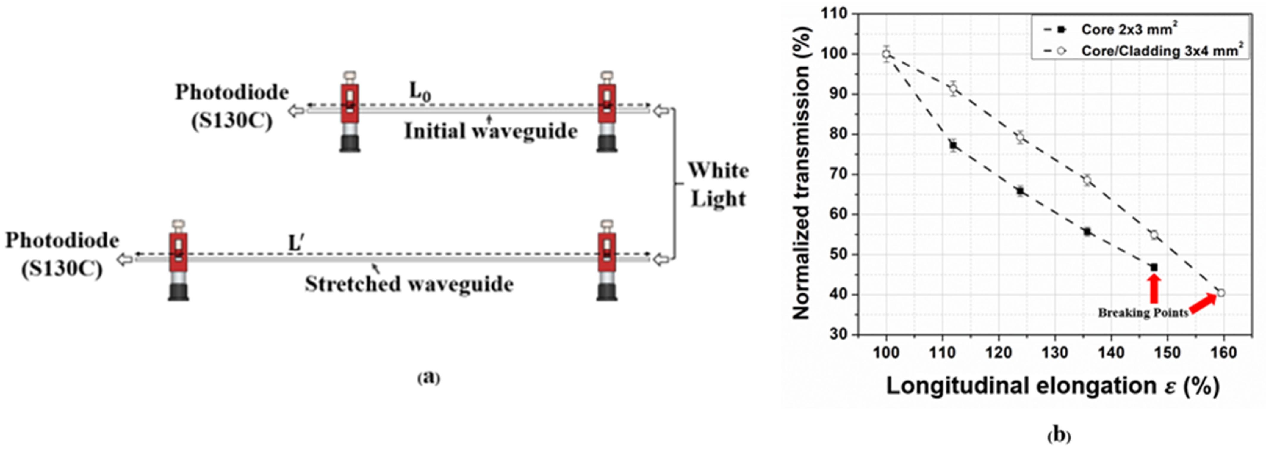
3.2. Longitudinal Elongation

To characterize the waveguide’s response to longitudinal elongation, the waveguide was first fixed using clamps at its initial rest position and the transmission output was measured (Figure 7a). The waveguide was then stretched in increments of 2.5 cm (and the corresponding optical transmission measured) until the breaking point was reached, as indicated by the red arrows in (Figure 7b). The results indicated that the air-clad waveguide was stretchable up to 150% elongation, and the one with solid PDMS cladding was stretchable up to 160% (Figure 6b). This test was performed with the same sample (i.e. either the air-clad waveguide or the solid-clad PDMS waveguide) for only one cycle per elongation point. We believe that performing a durability test with 1000 cycles or more would also be interesting, but defer this type of measurement to a future article that will discuss the integration of such PDMS waveguides into a fully packaged sensor solution. We note that the prior reported tests on similar PDMS samples indicated that an elongation of up to 200% could be achieved without permanent damage to samples for shorter time durations (approximately 50 s) [37].

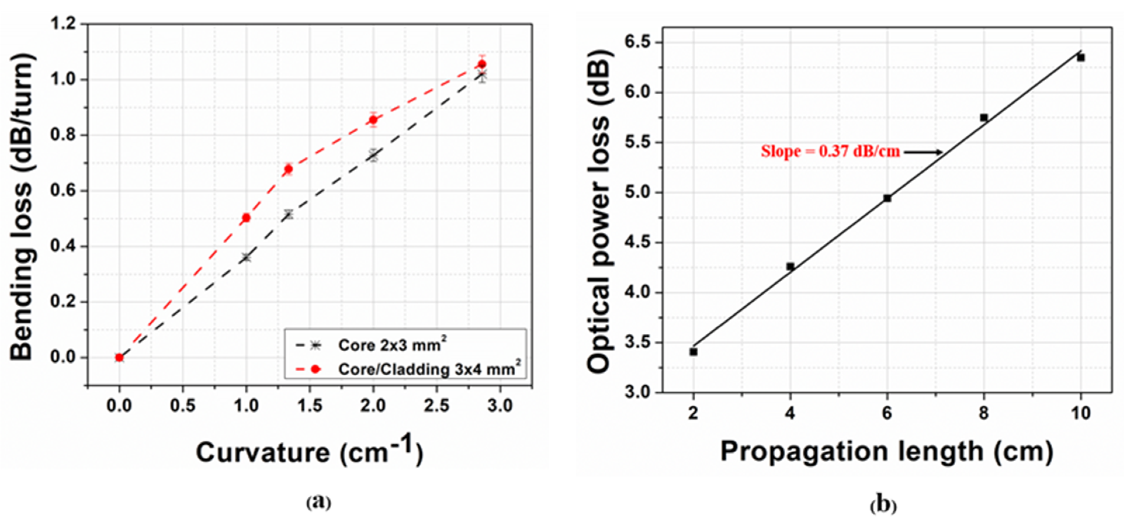
3.3. Bending and Propagation Loss Measurements

The bending loss ( γ B ) in dB/turn units was assessed using a 3D printed cylindrical pyramid of varying diameters (7 mm, 10 mm, 15 mm, and 20 mm) disposed in stages. The waveguide under test was subsequently coiled around one of the diameters of the pyramid, with as many turns as possible (Figure 8), while making sure to not exert a longitudinal elongation (i.e. stretching) during these tests.
The waveguide bending loss in dB/turn was evaluated through the following formula:
γ B = 10 N log 10 ( P i n P o u t )
where N is the number of turns, and Pin and Pout denote the input and output optical power, respectively. Since our PDMS waveguides are very flexible, they can sustain very tight bending radii that enable to conform to arbitrary surface body shapes. Both tested waveguides (Figure 9a) demonstrated relatively small bending losses (<1.2 dB/turn), with the solid core/cladding waveguide exhibiting slightly higher bending loss values, owing to its weaker optical mode confinement, due to a lower core-clad refractive index contrast.
The propagation loss of the air-clad PDMS waveguide was evaluated via the cutback technique, whereas the output transmitted optical power was measured through gradually decreasing lengths of the same waveguide (after cutting one end using a sharp razor blade). This measurement was repeated at an interval of 2 cm cut lengths of the waveguide (Figure 9b). The slope of the linear regression indicated a loss of 0.37 dB/cm inside this flexible PDMS waveguide, which is in close agreement with similar waveguides reported previously [40]. We expect a comparable result for the solid core-clad PDMS waveguide.

3.4. Waveguide Thermal Stability

We performed an experimental test to evaluate the PDMS waveguide’s optical response to changes in temperatures. In this test, the air-clad PDMS waveguide sample was subjected at 21 °C and 38 °C and a fixed pressure of 150 mmHg, for 5 repetitions each. The test results below (Figure 10) show that the average normalized optical transmission for 21 °C and 38 °C were, respectively, (85.9 ± 0.9)% and (85.4 ± 2)%. Hence, we measured a very low difference (0.5%) in the average transmission between the two temperatures, which is below the measurement error. Moreover, we believe that since our sensor uses normalized optical transmission (with respect to the unperturbed case) this approach allows us to essentially remove any temperature dependence. We believe that, similarly to the temperature response study above, the PDMS waveguide sensor would show a negligible optical dependence on changes in humidity, owing to the same normalization procedure.

4. Conclusions

We demonstrated the fabrication of millimeter-sized flexible and stretchable silicone PDMS optical waveguides using a solvent-free process. The waveguide core refractive index was engineered through the incorporation of benzophenone (BPh) dopant and subsequently demonstrated a high change in refractive index. We also demonstrated how to precisely control the refractive index of the core/clad waveguides through proper tuning of the PDMS (to curing agent) mixing ratio and BPh doping concentration, with a predictive model. We showed that such low–loss (0.37 dB/cm) flexible waveguides can be used for monitoring an applied pressure in a meaningful range for biomedical applications, thanks to a high sensitivity on the order of 0.06 to 0.10%/dB optical loss. These results are another step toward robust, compact, and flexible wearable pressure sensors based on stretchable polymer optical waveguides.

Author Contributions

K.N.A., A.A.R., J.-M.L. and B.U. conceived the experiments. K.N.A., A.A.R. and D.S. conducted the experiments. K.N.A., A.A.R., A.R.-D., J.-M.M.-T., Y.P., J.-M.L. and B.U. worked on the modelling and interpretation of the results. A.R.-D., J.-M.M.-T., Y.P., J.-M.L. and B.U. supervised the project as well as provided the resources. S.K.M. investigation and validation. All authors have read and agreed to the published version of the manuscript.

Funding

This research was funded by the Social Sciences and Humanities Research Council of Canada’s New Frontiers in Research Fund program (#NFRFE-2019-00822), and the Natural Sciences and Engineering Research Council of Canada’s Discovery Grants (#RGPIN-2015-04463).

Institutional Review Board Statement

This research was approved by the Research ethics committee of the Centre intégré universitaire de santé et de services sociaux du Nord-de-l’Île-de-Montréal (protocol code #CF00145582, dated: 31 March 2020).

Informed Consent Statement

Not applicable.

Data Availability Statement

Data is contained within the article.

Conflicts of Interest

The authors declare no conflict of interest.

References

  1. Butt, M.A.; Kazanskiy, N.L.; Khonina, S.N. Revolution in Flexible Wearable Electronics for Temperature and Pressure Monitoring—A Review. Electronics 2022, 11, 716. [Google Scholar] [CrossRef]
  2. Farooq, M.; Iqbal, T.; Vazquez, P.; Farid, N.; Thampi, S.; Wijns, W.; Shahzad, A. Thin-Film Flexible Wireless Pressure Sensor for Continuous Pressure Monitoring in Medical Applications. Sensors 2020, 20, 6653. [Google Scholar] [CrossRef] [PubMed]
  3. Fong, D.T.-P.; Chan, Y.-Y.; Hong, Y.; Yung, P.S.-H.; Fung, K.-Y.; Chan, K.-M. A three-pressure-sensor (3PS) system for monitoring ankle supination torque during sport motions. J. Biomech. 2008, 41, 2562–2566. [Google Scholar] [CrossRef] [Green Version]
  4. Li, L.; Zheng, J.; Chen, J.; Luo, Z.; Su, Y.; Tang, W.; Gao, X.; Li, Y.; Cao, C.; Liu, Q.; et al. Flexible Pressure Sensors for Biomedical Applications: From Ex Vivo to In Vivo. Adv. Mater. Interfaces 2020, 7, 2000743. [Google Scholar] [CrossRef]
  5. Meng, K.; Xiao, X.; Wei, W.-X.; Chen, G.-R.; Nashalian, A.; Shen, S.; Chen, J. Wearable Pressure Sensors for Pulse Wave Monitoring. Adv. Mater. 2022, 34, 2109357. [Google Scholar] [CrossRef]
  6. Rum, L.; Sten, O.; Vendrame, E.; Belluscio, V.; Camomilla, V.; Vannozzi, G.; Truppa, L.; Notarantonio, M.; Sciarra, T.; Lazich, A.; et al. Wearable Sensors in Sports for Persons with Disability: A Systematic Review. Sensors 2021, 21, 1858. [Google Scholar] [CrossRef] [PubMed]
  7. Shen, G. Recent advances of flexible sensors for biomedical applications. Prog. Nat. Sci. Mater. Int. 2021, 31, 872–882. [Google Scholar] [CrossRef]
  8. Zhang, J.-W.; Zhang, Y.; Li, Y.-Y.; Wang, P. Textile-Based Flexible Pressure Sensors: A Review. Polym. Rev. 2022, 62, 65–94. [Google Scholar] [CrossRef]
  9. Chenu, O.; Vuillerme, N.; Bucki, M.; Diot, B.; Cannard, F.; Payan, Y. TexiCare: An innovative embedded device for pressure ulcer prevention. Preliminary results with a paraplegic volunteer. J. Tissue Viability 2013, 22, 83–90. [Google Scholar]
  10. Chhetry, A.; Yoon, H.; Park, J.Y. A flexible and highly sensitive capacitive pressure sensor based on conductive fibers with a microporous dielectric for wearable electronics. J. Mater. Chem. C 2017, 5, 10068–10076. [Google Scholar] [CrossRef]
  11. Choi, D.; Jang, S.; Kim, J.S.; Kim, H.-J.; Kim, D.H.; Kwon, J.-Y. A Highly Sensitive Tactile Sensor Using a Pyramid-Plug Structure for Detecting Pressure, Shear Force, and Torsion. Adv. Mater. Technol. 2019, 4, 1800284. [Google Scholar] [CrossRef]
  12. Hayn, D.; Falgenhauer, M.; Morak, J.; Wipfler, K.; Willner, V.; Liebhart, W.; Schreier, G. An eHealth System for Pressure Ulcer Risk Assessment Based on Accelerometer and Pressure Data. J. Sens. 2015, 2015, 106537. [Google Scholar] [CrossRef]
  13. Homayounfar, S.Z.; Andrew, T.L. Wearable Sensors for Monitoring Human Motion: A Review on Mechanisms, Materials, and Challenges. SLAS Technol. Transl. Life Sci. Innov. 2020, 25, 9–24. [Google Scholar] [CrossRef] [PubMed]
  14. Owings, T.M.; Apelqvist, J.; Stenström, A.; Becker, M.; Bus, S.A.; Kalpen, A.; Ulbrecht, J.S.; Cavanagh, P.R. Plantar pressures in diabetic patients with foot ulcers which have remained healed. Diabet. Med. 2009, 26, 1141–1146. [Google Scholar] [CrossRef] [PubMed]
  15. Chen, W.F.; Yan, X. Progress in achieving high-performance piezoresistive and capacitive flexible pressure sensors. J. Mater. Sci. Technol. 2020, 43, 175–188. [Google Scholar] [CrossRef]
  16. Correia, R.; James, S.W.; Lee, S.-W.; Morgan, S.P.; Korposh, S. Biomedical application of optical fibre sensors. J. Opt. 2018, 20, 073003. [Google Scholar] [CrossRef]
  17. Mishra, S.; Mac-Thiong, J.-M.; Wagnac, E.; Petit, Y.; Ung, B. A Sensitive and Fast Fiber Bragg Grating-Based Investigation of the Biomechanical Dynamics of In Vitro Spinal Cord Injuries. Sensors 2021, 21, 1671. [Google Scholar] [CrossRef]
  18. Roriz, P.; Frazão, O.; Ribeiro, A.L.; Santos, J.L.; Simões, J.A. Review of fiber-optic pressure sensors for biomedical and biomechanical applications. J. Biomed. Opt. 2013, 18, 050903. [Google Scholar] [CrossRef]
  19. Wang, W.-C.; LeDoux, W.R.; Sangeorzan, B.J.; Reinhall, P.G. A shear and plantar pressure sensor based on fiber-optic bend loss. J. Rehabil. Res. Dev. 2005, 42, 315–326. [Google Scholar] [CrossRef]
  20. Zhang, X.Y.; Yang, L.Z.Y. A fiber Bragg grating quasi distributed sensing network with a wavelength-tunable chaotic fiber laser. Syst. Sci. Control. Eng. An Open Access J. 2014, 2, 268–274. [Google Scholar] [CrossRef] [Green Version]
  21. Arute, V.K.; Syed, A.; Khandelwal, A. Time–space–weight calibrated plastic optical fiber-based pressure sensing carpet. Opt. Eng. 2021, 60, 094106. [Google Scholar] [CrossRef]
  22. Shibata, Y.; Nishimura, A.; Niwa, S.; Osawa, Y.; Uemiya, T. Optical Sensors. U.S. Patent 4,750,796, 14 June 1988. [Google Scholar]
  23. Begej, S. Planar and finger-shaped optical tactile sensors for robotic applications. IEEE Trans. Robot. Autom 1988, 4, 472–484. [Google Scholar] [CrossRef]
  24. Kookootsedes, G.J.; Reese, H.H.; Gutek, B.I.; Pretzer, G.H. Touch position sensitive optical waveguides. U.S. Patent 4,701,017, 20 October 1987. [Google Scholar]
  25. Lagakos, N.; Schnaus, E.; Cole, J.; Jarzynski, J.; Bucaro, J. Optimizing fiber coatings for interferometric acoustic sensors. IEEE Trans. Microw. Theory Tech. 1982, 30, 529–535. [Google Scholar] [CrossRef] [Green Version]
  26. Lieberman, R.A.; Blyler, L.L.; Cohen, L.G. A distributed fiber optic sensor based on cladding fluorescence. J. Lightwave Technol. 1990, 8, 212–220. [Google Scholar] [CrossRef]
  27. Schueller, O.J.A.; Zhao, X.-M.; Whitesides, G.M.; Smith, S.P.; Prentiss, M. Fabrication of Liquid-Core Waveguides by Soft Lithography. Adv. Mater. 1999, 11, 37–41. [Google Scholar] [CrossRef]
  28. Babar Jamil, Y.C. Soft Optical Waveguide Sensors Tuned by Reflective Pigmentation for Robotic Applications. J. Korea Robot. Soc. 2021, 16, 1–11. [Google Scholar] [CrossRef]
  29. Bai, H.; Li, S.; Barreiros, J.; Tu, Y.; Pollock, C.R.; Shepherd, R.F. Stretchable distributed fiber-optic sensors. Science 2020, 370, 848–852. [Google Scholar] [CrossRef]
  30. Guo, J.; Niu, M.; Yang, C. Highly flexible and stretchable optical strain sensing for human motion detection. Optica 2017, 4, 1285–1288. [Google Scholar] [CrossRef]
  31. Harnett, C.K.; Zhao, H.; Shepherd, R.F. Stretchable Optical Fibers: Threads for Strain-Sensitive Textiles. Adv. Mater. Technol. 2017, 2, 1700087. [Google Scholar] [CrossRef]
  32. Ramuz, M.; Tee, B.C.-K.; Tok, J.B.-H.; Bao, Z. Transparent, Optical, Pressure-Sensitive Artificial Skin for Large-Area Stretchable Electronics. Adv. Mater. 2012, 24, 3223–3227. [Google Scholar] [CrossRef]
  33. Sandt, J.D.; Moudio, M.; Clark, J.K.; Hardin, J.; Argenti, C.; Carty, M.; Lewis, J.A.; Kolle, M. Stretchable Optomechanical Fiber Sensors for Pressure Determination in Compressive Medical Textiles. Adv. Healthc. Mater. 2018, 7, e1800293. [Google Scholar] [CrossRef] [PubMed]
  34. Surapaneni, R.; Park, K.; Suster, M.; Young, D.; Mastrangelo, C.H. A highly sensitive flexible pressure and shear sensor array for measurement of ground reactions in pedestrian navigation. In Proceedings of the 2011 16th International Solid-State Sensors, Actuators and Microsystems Conference, Beijing, China, 5–9 June 2011. [Google Scholar]
  35. To, C.; Hellebrekers, T.L.; Park, Y. Highly stretchable optical sensors for pressure, strain, and curvature measurement. Presented at 2015 IEEE/RSJ International Conference on Intelligent Robots and Systems (IROS), Hamburg, Germany, 28 September 2015. [Google Scholar]
  36. Toyama, S.; Tanaka, Y.; Shirogane, S.; Nakamura, T.; Umino, T.; Uehara, R.; Okamoto, T.; Igarashi, H. Development of Wearable Sheet-Type Shear Force Sensor and Measurement System that is Insusceptible to Temperature and Pressure. Sensors 2017, 17, 1752. [Google Scholar]
  37. Zhao, H.; O’Brien, K.; Li, S.; Shepherd, R.F. Optoelectronically innervated soft prosthetic hand via stretchable optical waveguides. Sci. Robot. 2016, 1, eaai7529. [Google Scholar] [CrossRef] [PubMed] [Green Version]
  38. Missinne, J.; Kalathimekkad, S.; Van Hoe, B.; Bosman, E.; Vanfleteren, J.; Van Steenberge, G. Stretchable optical waveguides. Opt. Express 2014, 22, 4168–4179. [Google Scholar] [CrossRef] [Green Version]
  39. Panusa, G.; Pu, Y.; Wang, J.; Moser, C.; Psaltis, D. Fabrication of Sub-Micron Polymer Waveguides through Two-Photon Polymerization in Polydimethylsiloxane. Polymers 2020, 12, 2485. [Google Scholar] [CrossRef]
  40. Prajzler, V.; Neruda, M.; Nekvindová, P. Flexible multimode polydimethyl-diphenylsiloxane optical planar waveguides. J. Mater. Sci. Mater. Electron. 2018, 29, 5878–5884. [Google Scholar] [CrossRef]
  41. Miranda, I.; Souza, A.; Sousa, P.; Ribeiro, J.; Castanheira, E.M.S.; Lima, R.; Minas, G. Properties and Applications of PDMS for Biomedical Engineering: A Review. J. Funct. Biomater. 2022, 13, 2. [Google Scholar] [CrossRef]
  42. Ryabchun, A.; Sakhno, O.; Wegener, M. Conventional elastomers doped with benzophenone derivatives as effective media for all-optical fabrication of tunable diffraction elements. RSC Adv. 2016, 6, 51791–51800. [Google Scholar] [CrossRef]
  43. Kasap, S.O. Optoelectronics and Photonics; Pearson Education: London, UK, 2013. [Google Scholar]
  44. Nemoto, S. Measurement of the refractive index of liquid using laser beam displacement. Appl. Opt. 1992, 31, 6690–6694. [Google Scholar] [CrossRef]
  45. Sengupta, D.; Ung, B. Simple optical setup for the undergraduate experimental measurement of the refractive indices and attenuation coefficient of liquid samples and characterization of laser beam profile. In Proceedings of the Fifteenth Conference on Education and Training in Optics and Photonics: ETOP 2019, Quebec City, QC, Canada, 21–24 May 2019; Optica Publishing Group: Quebec, QC, Canada, 2019. [Google Scholar]
  46. Bute, M.G.; Shinde, S.D.; Bodas, D.; Fouad, H.; Adhi, K.P.; Gosavi, S.W. Benzophenone doped polydimethylsiloxane: Self developable composite resist system for its use in a direct write laser lithography application. J. Phys. D Appl. Phys. 2015, 48, 175301. [Google Scholar] [CrossRef]
  47. Kant, M.B.; Shinde, S.D.; Bodas, D.; Patil, K.; Sathe, V.; Adhi, K.; Gosavi, S. Surface studies on benzophenone doped PDMS microstructures fabricated using KrF excimer laser direct write lithography. Appl. Surf. Sci. 2014, 314, 292–300. [Google Scholar] [CrossRef]
Figure 1. Variation of the refractive index of PDMS-BPh as a function of the concentration of BPh in wt.%. Solid lines represent the fitting model of Equation (2).
Photonics 09 00557 g001
Figure 2. Waveguides manufacturing steps.
Photonics 09 00557 g002
Figure 3. (a) Photo of a waveguide illuminated with white light. (b) Core-air-clad and core-solid-clad waveguide transverse cross-section. (c) Normalized transmission spectrum of the PDMS-BPh waveguides (0.1% BPh/wt.) of 20 cm length.
Photonics 09 00557 g003
Figure 4. Scheme of the transverse compression test.
Photonics 09 00557 g004
Figure 5. Waveguide (0.1% BPh/wt.) sensitivity measurement: normalized transmission as a function of transverse compression and the relationship between the optical power loss as a function of the transverse compression, (a,b): 2 × 3 mm2, core/air-clad; (c,d): 3 × 4 mm2, core/cladding.
Photonics 09 00557 g005
Figure 6. Waveguides (0.1% BPh/wt.): normalized transmission as a function of pressure applied, (a): 2 × 3 mm2, core/air-clad; (b): 3 × 4 mm2, core/cladding.
Photonics 09 00557 g006
Figure 7. (a) Longitudinal elongation process. (b) Normalized transmission as a function of longitudinal elongation.
Photonics 09 00557 g007
Figure 8. Bending loss measurement setup.
Photonics 09 00557 g008
Figure 9. (a) Bending loss in dB/turn as a function of the radius of curvature. (b): PDMS-BPh waveguides (0.1%BPh/wt., core: 2 × 3 mm2) propagation loss measurement with the cutback method.
Photonics 09 00557 g009
Figure 10. Normalized transmission of the air-clad PDMS waveguide (2 × 3 mm2) under a fixed 150 mmHg load in the y-direction for 5 repetitions.
Photonics 09 00557 g010
Publisher’s Note: MDPI stays neutral with regard to jurisdictional claims in published maps and institutional affiliations.

